EP1169585B1 - Self-centering brush seal - Google Patents
Self-centering brush seal Download PDFInfo
- Publication number
- EP1169585B1 EP1169585B1 EP00905872A EP00905872A EP1169585B1 EP 1169585 B1 EP1169585 B1 EP 1169585B1 EP 00905872 A EP00905872 A EP 00905872A EP 00905872 A EP00905872 A EP 00905872A EP 1169585 B1 EP1169585 B1 EP 1169585B1
- Authority
- EP
- European Patent Office
- Prior art keywords
- brush seal
- groove
- component
- segments
- radial
- Prior art date
- Legal status (The legal status is an assumption and is not a legal conclusion. Google has not performed a legal analysis and makes no representation as to the accuracy of the status listed.)
- Expired - Lifetime
Links
Images


Classifications
-
- F—MECHANICAL ENGINEERING; LIGHTING; HEATING; WEAPONS; BLASTING
- F16—ENGINEERING ELEMENTS AND UNITS; GENERAL MEASURES FOR PRODUCING AND MAINTAINING EFFECTIVE FUNCTIONING OF MACHINES OR INSTALLATIONS; THERMAL INSULATION IN GENERAL
- F16J—PISTONS; CYLINDERS; SEALINGS
- F16J15/00—Sealings
- F16J15/16—Sealings between relatively-moving surfaces
- F16J15/32—Sealings between relatively-moving surfaces with elastic sealings, e.g. O-rings
- F16J15/3284—Sealings between relatively-moving surfaces with elastic sealings, e.g. O-rings characterised by their structure; Selection of materials
- F16J15/3288—Filamentary structures, e.g. brush seals
Definitions
- Rotary machines such as steam and gas turbines, used for power generation and mechanical drive applications, are generally large machines consisting of multiple turbine stages.
- hot high pressure fluid flowing through the turbine stages must pass through a series of stationary and rotating components and seals between the stationary and rotating components are used to control leakage. Seals are also employed in other areas of the turbine than in the hot gas path; e.g., in end packings between the rotating shaft and the stationary components. Turbine efficiency is directly dependent upon the ability of the seals to prevent leakage.
Description
Consequently, the axis of the brush seal and the shaft have common axes, notwithstanding radial excursions of the axis of the
Claims (8)
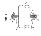
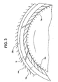
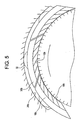
- A rotary machine comprising:characterised by said brush seal (10) including a plurality of arcuate, circumferentially extending segments (30) disposed in part in said groove and a spring (32) biasing each segment for movement in a radial inward direction to maintain the bristles carried by said segments in contact with said rotatable component.a component (12) rotatable about an axis (A) and a component (14) fixed against rotation about said axis, said fixed component having a circumferentially extending groove (24) opening toward said rotatable component;a brush seal (10) disposed in said groove and including a plurality of bristles (16) and a support (18, 20) for said bristles, said bristles being secured to said support and projecting therefrom beyond said support into sealing engagement with said rotatable component; andsaid brush seal and said groove having a radial clearance therebetween enabling the brush seal for radial movement to maintain substantial concentricity and sealing engagement with the rotatable component, notwithstanding deviation of the axis of rotation of said rotatable component relative to the axis of said fixed component,said rotatable component (12) lying radially inwardly of said fixed component (14),
- A machine according to Claim 1 wherein said groove (24) and said brush seal (10) cooperate with one another without substantial radial constraint therebetween, enabling the brush seal for free-floating radial excursions within said groove and concentricity with the rotatable component.
- A machine according to Claim 1 wherein said spring (32) includes a circumferentially extending helical coil spring extending in said groove in contact with each segment to bias the segment radially inwardly.
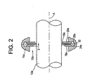
- A machine according to Claim 1 wherein said rotatable component lies radially inwardly of said fixed component, said brush seal including a plurality of arcuate, circumferentially extending segments (30b) disposed in part in said groove and springs (32') disposed between said stationary component and said segments for biasing said segments, respectively, for movement in a radial inward direction to maintain the bristles carried by said segments in contact with said rotatable component.
- A machine according to Claim 1 wherein said brush seal includes a plurality of arcuate, circumferentially extending segments (30b) disposed in part in said groove and a spring (32') for each segment and extending between said segment and a base of said groove.
- A machine according to Claim 5 wherein each of said springs (32') comprises a leaf spring.
- A machine according to Claim 1 wherein said rotatable component lies radially inwardly of said fixed component, said brush seal including a plurality of arcuate, circumferentially extending segments disposed in part in said groove and a spring biasing each segment for movement in a radial inward direction to maintain the bristles carried by said segments in contact with said rotatable component, said brush seal forming a seal between high and low pressure regions on respective upstream and downstream sides of said brush seal, a seal (44) between said brush seal and said groove dividing the groove into two chambers (46, 48), a passage (45) in said stationary component in communication with the downstream low pressure side of said brush seal for communicating low pressure fluid from said downstream side to one of said chambers to balance the pressures along the inside and outside diameters of said brush seal.
- A machine according to Claim 1 including an anti-rotation stop (72) carried by said fixed component and engaging said brush seal to prevent circumferential movement of said brush seal, while enabling radial movement thereof.
Applications Claiming Priority (1)
| Application Number | Priority Date | Filing Date | Title |
|---|---|---|---|
| PCT/US2000/002439 WO2001055625A1 (en) | 2000-01-31 | 2000-01-31 | Self-centering brush seal |
Publications (2)
| Publication Number | Publication Date |
|---|---|
| EP1169585A1 EP1169585A1 (en) | 2002-01-09 |
| EP1169585B1 true EP1169585B1 (en) | 2005-03-02 |
Family
ID=21741017
Family Applications (1)
| Application Number | Title | Priority Date | Filing Date |
|---|---|---|---|
| EP00905872A Expired - Lifetime EP1169585B1 (en) | 2000-01-31 | 2000-01-31 | Self-centering brush seal |
Country Status (5)
| Country | Link |
|---|---|
| EP (1) | EP1169585B1 (en) |
| JP (1) | JP2003521649A (en) |
| KR (1) | KR100659414B1 (en) |
| DE (1) | DE60018396T2 (en) |
| WO (1) | WO2001055625A1 (en) |
Families Citing this family (15)
| Publication number | Priority date | Publication date | Assignee | Title |
|---|---|---|---|---|
| US6669202B1 (en) | 2002-06-27 | 2003-12-30 | General Electric Co. | Multi-core brush seal assembly for rotary machines |
| US7093835B2 (en) * | 2002-08-27 | 2006-08-22 | United Technologies Corporation | Floating brush seal assembly |
| GB2407626A (en) * | 2003-10-31 | 2005-05-04 | Rolls Royce Plc | Suspended seal arrangement |
| JP4822716B2 (en) * | 2005-02-07 | 2011-11-24 | 三菱重工業株式会社 | Gas turbine with seal structure |
| US8490981B2 (en) * | 2010-02-23 | 2013-07-23 | General Electric Company | Brush seal |
| US8328198B2 (en) | 2010-10-06 | 2012-12-11 | General Electric Company | Brush seal |
| US8628092B2 (en) * | 2010-11-30 | 2014-01-14 | General Electric Company | Method and apparatus for packing rings |
| US8794918B2 (en) | 2011-01-07 | 2014-08-05 | General Electric Company | System for adjusting brush seal segments in turbomachine |
| US9121297B2 (en) | 2011-03-28 | 2015-09-01 | General Electric Company | Rotating brush seal |
| US9255486B2 (en) | 2011-03-28 | 2016-02-09 | General Electric Company | Rotating brush seal |
| JP5134703B2 (en) * | 2011-04-27 | 2013-01-30 | 三菱重工業株式会社 | Gas turbine with seal structure |
| KR101945921B1 (en) | 2015-01-29 | 2019-02-11 | 이구루코교 가부시기가이샤 | Brush seal |
| KR101898389B1 (en) * | 2017-06-20 | 2018-09-12 | 두산중공업 주식회사 | Brush seal assembly |
| CN107630721B (en) * | 2017-10-12 | 2023-10-03 | 昆明理工大学 | Equal-split circumference spliced brush type seal |
| CN109458228B (en) * | 2019-01-11 | 2023-08-15 | 沈阳航空航天大学 | Brush type sealing structure allowing rotor to rotate reversely |
Family Cites Families (4)
| Publication number | Priority date | Publication date | Assignee | Title |
|---|---|---|---|---|
| GB9020317D0 (en) * | 1990-09-18 | 1990-10-31 | Cross Mfg Co | Sealing devices |
| US5351971A (en) * | 1993-05-21 | 1994-10-04 | Eg&G Sealol, Inc. | Brush seal device having a floating backplate |
| US5997004A (en) * | 1996-10-22 | 1999-12-07 | Flowserve Management Company | Hybrid floating brush seal |
| US6139018A (en) * | 1998-03-25 | 2000-10-31 | General Electric Co. | Positive pressure-actuated brush seal |
-
2000
- 2000-01-31 JP JP2001555726A patent/JP2003521649A/en not_active Ceased
- 2000-01-31 KR KR1020017012402A patent/KR100659414B1/en not_active IP Right Cessation
- 2000-01-31 EP EP00905872A patent/EP1169585B1/en not_active Expired - Lifetime
- 2000-01-31 DE DE60018396T patent/DE60018396T2/en not_active Expired - Lifetime
- 2000-01-31 WO PCT/US2000/002439 patent/WO2001055625A1/en active IP Right Grant
Also Published As
| Publication number | Publication date |
|---|---|
| DE60018396D1 (en) | 2005-04-07 |
| WO2001055625A1 (en) | 2001-08-02 |
| KR20010112379A (en) | 2001-12-20 |
| DE60018396T2 (en) | 2005-12-29 |
| JP2003521649A (en) | 2003-07-15 |
| KR100659414B1 (en) | 2006-12-18 |
| EP1169585A1 (en) | 2002-01-09 |
Similar Documents
| Publication | Publication Date | Title |
|---|---|---|
| US6168162B1 (en) | Self-centering brush seal | |
| EP1169585B1 (en) | Self-centering brush seal | |
| US6250641B1 (en) | Positive biased packing ring brush seal combination | |
| US6719296B2 (en) | Seal for a rotating member | |
| US6065754A (en) | Uniform clearance, temperature responsive, variable packing ring | |
| US6131910A (en) | Brush seals and combined labyrinth and brush seals for rotary machines | |
| US7344357B2 (en) | Methods and apparatus for assembling a rotary machine | |
| US20090315272A1 (en) | Brush seal device | |
| US6250640B1 (en) | Brush seals for steam turbine applications | |
| US6161836A (en) | Brush seal and rotary machine containing such brush seal | |
| US8181967B2 (en) | Variable clearance packing ring | |
| EP0816726B1 (en) | Brush seals and combined labyrinth and brush seals for rotary machines | |
| JP4740494B2 (en) | Turbine rotor-stator spring plate seal and related methods | |
| CN102135019A (en) | Method and apparatus for labyrinth seal packing rings | |
| EP1169587A1 (en) | Positive biased packing ring brush seal combination | |
| US7484927B2 (en) | Steam turbine variable clearance packing | |
| US20100143102A1 (en) | Compliant plate seal with self-correcting behavior | |
| EP1169586B1 (en) | Brush seals for steam turbine applications | |
| EP0382333B1 (en) | Mounting arrangement of segmental members in rotary machines | |
| US11287043B2 (en) | High clearance seal assembly | |
| US20040222596A1 (en) | Steam turbine packing spring | |
| EP1890060A1 (en) | A variable clearance packing ring | |
| GB2225394A (en) | Shaft sealing arrangement | |
| JP2021085527A (en) | Circumferential seal assembly | |
| EP3184753B1 (en) | Sealing structure for turbine |
Legal Events
| Date | Code | Title | Description |
|---|---|---|---|
| PUAI | Public reference made under article 153(3) epc to a published international application that has entered the european phase |
Free format text: ORIGINAL CODE: 0009012 |
|
| AK | Designated contracting states |
Kind code of ref document: A1 Designated state(s): AT BE CH CY DE DK ES FI FR GB GR IE IT LI LU MC NL PT SE |
|
| 17P | Request for examination filed |
Effective date: 20020204 |
|
| 17Q | First examination report despatched |
Effective date: 20031125 |
|
| RBV | Designated contracting states (corrected) |
Designated state(s): DE FR GB |
|
| GRAP | Despatch of communication of intention to grant a patent |
Free format text: ORIGINAL CODE: EPIDOSNIGR1 |
|
| GRAS | Grant fee paid |
Free format text: ORIGINAL CODE: EPIDOSNIGR3 |
|
| GRAA | (expected) grant |
Free format text: ORIGINAL CODE: 0009210 |
|
| AK | Designated contracting states |
Kind code of ref document: B1 Designated state(s): DE FR GB |
|
| REG | Reference to a national code |
Ref country code: GB Ref legal event code: FG4D |
|
| REG | Reference to a national code |
Ref country code: IE Ref legal event code: FG4D |
|
| REF | Corresponds to: |
Ref document number: 60018396 Country of ref document: DE Date of ref document: 20050407 Kind code of ref document: P |
|
| ET | Fr: translation filed | ||
| PLBE | No opposition filed within time limit |
Free format text: ORIGINAL CODE: 0009261 |
|
| STAA | Information on the status of an ep patent application or granted ep patent |
Free format text: STATUS: NO OPPOSITION FILED WITHIN TIME LIMIT |
|
| 26N | No opposition filed |
Effective date: 20051205 |
|
| PGFP | Annual fee paid to national office [announced via postgrant information from national office to epo] |
Ref country code: FR Payment date: 20100205 Year of fee payment: 11 |
|
| PGFP | Annual fee paid to national office [announced via postgrant information from national office to epo] |
Ref country code: GB Payment date: 20100125 Year of fee payment: 11 Ref country code: DE Payment date: 20100127 Year of fee payment: 11 |
|
| GBPC | Gb: european patent ceased through non-payment of renewal fee |
Effective date: 20110131 |
|
| REG | Reference to a national code |
Ref country code: FR Ref legal event code: ST Effective date: 20110930 |
|
| PG25 | Lapsed in a contracting state [announced via postgrant information from national office to epo] |
Ref country code: FR Free format text: LAPSE BECAUSE OF NON-PAYMENT OF DUE FEES Effective date: 20110131 |
|
| PG25 | Lapsed in a contracting state [announced via postgrant information from national office to epo] |
Ref country code: GB Free format text: LAPSE BECAUSE OF NON-PAYMENT OF DUE FEES Effective date: 20110131 |
|
| REG | Reference to a national code |
Ref country code: DE Ref legal event code: R119 Ref document number: 60018396 Country of ref document: DE Effective date: 20110802 |
|
| PG25 | Lapsed in a contracting state [announced via postgrant information from national office to epo] |
Ref country code: DE Free format text: LAPSE BECAUSE OF NON-PAYMENT OF DUE FEES Effective date: 20110802 |