EP1168820B1 - Stochastic threshold array generating system and method for generating an error map for image rendering - Google Patents
Stochastic threshold array generating system and method for generating an error map for image rendering Download PDFInfo
- Publication number
- EP1168820B1 EP1168820B1 EP01119962A EP01119962A EP1168820B1 EP 1168820 B1 EP1168820 B1 EP 1168820B1 EP 01119962 A EP01119962 A EP 01119962A EP 01119962 A EP01119962 A EP 01119962A EP 1168820 B1 EP1168820 B1 EP 1168820B1
- Authority
- EP
- European Patent Office
- Prior art keywords
- pattern
- stochastic
- error map
- stochastic pattern
- generating
- Prior art date
- Legal status (The legal status is an assumption and is not a legal conclusion. Google has not performed a legal analysis and makes no representation as to the accuracy of the status listed.)
- Expired - Lifetime
Links
- 238000009877 rendering Methods 0.000 title claims description 120
- 238000000034 method Methods 0.000 title claims description 45
- 239000002131 composite material Substances 0.000 claims description 92
- 238000003491 array Methods 0.000 claims description 48
- 238000001914 filtration Methods 0.000 claims description 26
- 230000004044 response Effects 0.000 claims description 21
- 230000035945 sensitivity Effects 0.000 claims description 14
- 239000003086 colorant Substances 0.000 claims description 7
- 230000002776 aggregation Effects 0.000 claims description 6
- 238000004220 aggregation Methods 0.000 claims description 6
- 230000000295 complement effect Effects 0.000 claims description 6
- 230000000007 visual effect Effects 0.000 claims description 6
- 230000006870 function Effects 0.000 description 44
- 230000000875 corresponding effect Effects 0.000 description 14
- 238000010586 diagram Methods 0.000 description 11
- 238000009792 diffusion process Methods 0.000 description 11
- 230000008569 process Effects 0.000 description 8
- 238000009826 distribution Methods 0.000 description 6
- 230000000694 effects Effects 0.000 description 5
- 239000011159 matrix material Substances 0.000 description 5
- 230000002093 peripheral effect Effects 0.000 description 4
- 238000003860 storage Methods 0.000 description 4
- 230000008859 change Effects 0.000 description 3
- 238000012216 screening Methods 0.000 description 3
- 238000005457 optimization Methods 0.000 description 2
- 230000001276 controlling effect Effects 0.000 description 1
- 230000002596 correlated effect Effects 0.000 description 1
- 230000001419 dependent effect Effects 0.000 description 1
- 230000002040 relaxant effect Effects 0.000 description 1
- 230000000717 retained effect Effects 0.000 description 1
- 238000002922 simulated annealing Methods 0.000 description 1
- 230000007704 transition Effects 0.000 description 1
Images


Classifications
-
- H—ELECTRICITY
- H04—ELECTRIC COMMUNICATION TECHNIQUE
- H04N—PICTORIAL COMMUNICATION, e.g. TELEVISION
- H04N1/00—Scanning, transmission or reproduction of documents or the like, e.g. facsimile transmission; Details thereof
- H04N1/40—Picture signal circuits
- H04N1/405—Halftoning, i.e. converting the picture signal of a continuous-tone original into a corresponding signal showing only two levels
- H04N1/4051—Halftoning, i.e. converting the picture signal of a continuous-tone original into a corresponding signal showing only two levels producing a dispersed dots halftone pattern, the dots having substantially the same size
-
- H—ELECTRICITY
- H04—ELECTRIC COMMUNICATION TECHNIQUE
- H04N—PICTORIAL COMMUNICATION, e.g. TELEVISION
- H04N1/00—Scanning, transmission or reproduction of documents or the like, e.g. facsimile transmission; Details thereof
- H04N1/40—Picture signal circuits
- H04N1/403—Discrimination between the two tones in the picture signal of a two-tone original
Definitions
- the invention relates generally to the field of processing and rendering of digital images and more particularly to systems and methods for generating-stochastic threshold arrays for use in generating discrete-tone image data, such as halftone image data, in response to continuous-tone image data.
- the patent US 5, 214,517 describes a known method that produces a digital halftone image by providing a binary bit image pattern having a minimum visual noise for each density level in the image.
- the binary bit patterns are correlated in a manner that reduces visual noise resulting from transitions between patterns.
- the patterns are addressed by pixel density and x, y location to produce a halftone image.
- the patterns are generated by employing a stochastic minimization technique with a constraint to insure correlation between patterns.
- ULICHNEY R "The void-and-cluster method for dither array generation" PROCEEDINGS OF OF THE SPIE, vol./1913,1993, pages 332-343, BELLINGHAM, VA, US ISSN: 0277-786X describes a void-and-cluster method for generation of homogenous ordered dither arrays wherein each dither array is built by looking for voids and clusters in the intermediate patterns and relaxing them to optimise isotropy. The dither array is built from a prototype binary pattern which tiles the plane. To achieve a homogenous distribution, minority pixels should be removed from clusters or inserted into voids in order to reduce graininess.
- a region of the continuous-tone image which is fifty-percent gray, or half-way between black and white would be represented by a discrete-tone region in which one-half of the pixels would be white, and the other half would be black.
- each color is generally processed separately, so that pixel values representing the intensity of, for example, red, green and blue ("RGB”), cyan, magenta, and yellow (“CMY”), or cyan, magenta, yellow and black (“CMYK”) for the pixels in an image would be generated independently.
- RGB red, green and blue
- CMY cyan, magenta, yellow and black
- CMYK cyan, magenta, yellow and black
- error diffusion In one rendering technique, termed “error diffusion,” the continuous-tone image data is processed pixel by pixel, and discrete-tone pixel data is generated for each pixel. Error diffusion systems generally process the image data by scanning across successive lines in the image, generally starting from, for example, the upper left-hand corner of the image. In generating pixel data for the first pixel, an error diffusion system will generate a discrete-tone pixel value in response to the continuous tone pixel value for the pixel based on a selected threshold value.
- the discrete tone pixel value (either zero for black or two hundred and fifty five for white) will be determined based on whether it is above or below the threshold value, which will generally be selected to be half way through the range of values that the continuous tone pixel data may take on.
- the error diffusion system will also generate a discrete-tone pixel value in response to threshold value, but instead of only using the pixel's continuous-tone pixel value, it will generate an adjusted continuous-tone pixel value corresponding to the sum of its continuous-tone pixel value and the difference between the discrete-tone pixel value generated for the first pixel and the first pixel's continuous tone pixel value (that is, the "error"), the error being weighted according to a selected weighting function. The result is then compared to the threshold value and a discrete-tone pixel value generated in response.
- This operation is repeated for each pixel, across the first line, and across each pixels of successive lines, with an error-adjusted continuous tone pixel value being generated for each pixel using the errors generated for previously-processed pixels taken in relation to a weighting function.
- the point of this technique is that the errors, which, generally speaking relate to the difference between the luminance represented by the discrete-tone image data and the continuous-tone image data for correspondingly-positioned pixels, are diffused throughout the discrete-tone image from the upper left-hand corner of the image toward the right and downwardly through the image, with the degree of diffusion being related to the selected weighting function.
- the luminance represented by the discrete-tone pixel value for any particular pixel may be considerably different from the continuous-tone pixel level for a given pixel, over a group of pixels the errors tend to even out so that the discrete-tone image is perceptually similar to the continuous-tone image.
- stochastic screen In a system which operates in accordance with the stochastic screen technique, a stochastic threshold array is generated which has array elements organized in a selected number of rows and columns. Each array element of the stochastic threshold array is a threshold value.
- the stochastic threshold array is essentially tiled over the continuous-tone pixel values, and the discrete-tone pixel values are generated in response to a comparison between continuous-tone pixel values for the pixels and threshold values of correspondingly-positioned stochastic threshold array elements.
- the stochastic threshold array is generated from an optimized pattern, which in turn is generated from a seed pattern that comprises an array in which the various array elements are initially randomly assigned binary values.
- the seed pattern is processed to provide for selected distribution characteristics, and the stochastic threshold array generated after the distribution characteristics have been achieved.
- the optimized patterns and associated stochastic threshold arrays can be generated in advance of processing of the image data, since they normally do not depend on the continuous-tone image data for a particular image.
- the processing of the pixels can take place in parallel, which can speed up processing of the image as a whole.
- the primary problem is that they tend to produce undesirable artifacts, such as directional structures, in the discrete-tone image which are not present in the continuous-tone image.
- these artifacts are usually present in portions of an image which have constant or slowly-varying luminance.
- stochastic screen systems the artifacts may tend to appear as regular structures that correspond to the locations at which the edges of the tiled stochastic threshold arrays were tiled over the image.
- the systems tend to sharpen abrupt edges in an undesirable unidirectional way.
- each pixel will be rendered either by generating a dot or no dot, depending on its discrete-tone pixel value, on a recording medium. If the threshold values in the stochastic threshold arrays used in such systems are distributed so that clusters of relatively large aggregations of dots of any discrete-tone value will be generated, particularly for regions in an image having constant or slowly-varying luminance, then it is that the discrete-tone image will be relatively grainy, since such aggregations of uniformly-valued pixels may be visually perceptible.
- the discrete-tone image may exhibit an undesirable effect termed herein "mottle.”
- mottle is manifested as low-frequency variation of density over a region of a rendered image which is intended to be uniform. This can arise, for example, from variations in the process in which the discrete-tone image is rendered, resulting in variations in the sizes of the dots rendered on different portions of the medium.
- Changes in the proportion of the rendering medium covered by dots to that not covered by dots, in different regions of an image for which the luminance should be constant, can effectively change the luminance of the region as perceived by an observer.
- Significant variations in the sizes of dots can, for individual and small aggregations of dots of a discrete-tone image, operate to vary the luminance as perceived by the eye, since a significant variations in dot size for a number of dispersed dots as among different portions of a region can significantly change the relative proportion of the medium that is covered by dots to the amount that is not covered by dots as among those ' sections. This will be manifested as mottle.
- the invention provides a new and improved system and method for generating stochastic threshold arrays for use in rendering images.
- FIG. 1 is diagram of a computer system 10 including an image rendering system 20 ( FIG. 2 ).
- the computer system 10 in one embodiment includes a computer 14, one or more image acquisition devices represented by a camera 12A and a thirty-five millimeter slide scanner 12B (generally identified by reference numeral 12), for acquiring an image and converting it to continuous-tone digital image data, and one or more image rendering devices represented by a printer 13A and a raster image processor 13B (generally identified by reference numeral 13) for generating an output image.
- the computer 10 which in one embodiment is a general-purpose stored-program digital computer which comprises the image rendering system 20, receives the continuous-tone digital image data, and processes it in relation to stochastic threshold arrays as described below in connection with FIGS. 2 through 9E to generate discrete-tone digital image data to be rendered by, for example, an image rendering device 13.
- the computer 10 includes a processor module 14 and operator interface elements comprising operator input components such as a keyboard 15A and/or a mouse 15B (generally identified by reference numeral 15) and operator output elements such as a video display device 16.
- the processor module 14 includes, for example, processor, memory and mass storage devices such as disk and/or tape storage elements (not separately shown) which perform processing and storage operations in connection with digital data provided thereto.
- the computer system 10 will generally be processing certain programs which enable it to perform selected operations as described below in connection with FIGS. 2 through 9E .
- the operator input elements 15 are provided to permit an operator to input information for processing, including information for controlling the image processing operations.
- the video display device 16 is provided to display output information to the operator, such as information identifying certain selections the operator may make in connection with the processing of the image data.
- the computer system 10 is shown as comprising particular components, such as the keyboard and mouse for receiving input information from an operator, and a video display device for displaying output information to the operator, it will be appreciated that the computer system 10 may include a variety of components in addition to or instead of those depicted in FIG. 1 .
- the computer system 10 in one embodiment has been depicted as receiving continuous-tone image data from particular types of image acquisition devices 12, such as the camera 12A and a thirty-five millimeter scanner 12B, and particular types of image rendering devices 13, such as a printer 13A and a raster image processor 13B, it will be appreciated that numerous other types of image acquisition devices 12 and image rendering devices 13 may be used in connection with the computer system 10.
- image acquisition devices 12 such as the camera 12A and a thirty-five millimeter scanner 12B
- image rendering devices 13 such as a printer 13A and a raster image processor 13B
- image rendering system 20 may alternatively include special-purpose hardware and/or program components, or a combination of a computer system 10 with special-purpose hardware and/or program components.
- FIG. 2 is a functional block diagram of an image rendering system 20.
- the image rendering system 20 comprises a stochastic threshold array generation system 21 according to the invention, a stochastic threshold array library 22, and an image processing subsystem 23 which cooperate to receive input image data and generate in response thereto output image data.
- the image will be represented as a two-dimensional array of picture elements, or "pixels,” arranged in a number of rows and columns, and a input image data value is provided for each pixel.
- pixels two-dimensional array of picture elements
- a input image data value is provided for each pixel.
- the number of rows and columns of a input image data matrix will depend on the height and width of the image and the resolution, that is, the number of pixels per unit of distance along the height and width of the image.
- the input image data for each pixel comprises a value corresponding to the intensity of the pixel.
- the continuous tone image data for each pixel will have a value for each of the primary colors in which the image is encoded.
- the input image data is generally constrained to have values within a selected range, such as between zero and two hundred and fifty five, which can be quantized to an eight-bit digital data word.
- the image processing subsystem 23 in response to the input image data array, generates an output image data array having a plurality of array elements each corresponding to a array element of the input image data array, with each output image data array element containing a output image data value generated in response to the correspondingly-positioned element of the input image data array, but which is constrained to have two or only a few colorant density values which can be rendered by a rendering device.
- the stochastic threshold array generation system 21 which is described in more detail below in connection with FIGS. 3 through 9E , generates a plurality of optimized patterns and, using each optimized pattern so generated, generates a stochastic threshold array which it provides to the stochastic threshold array library 22.
- Each stochastic threshold array is essentially a matrix having matrix elements arrayed in a predetermined number of rows and columns, with each matrix element comprising a threshold value.
- the threshold values are compared to values of the input image data and output image data values are generated in response to the comparison.
- the stochastic threshold array generation system 21 generates a number of sets of stochastic threshold arrays, each set providing a particular trade-off between grain and mottle, as described above.
- the threshold arrays are generally generated such that the threshold values are distributed so as to provide a discrete-tone image when rendered by a rendering device 13 which locally maintains the average gray value of the input image and which is perceptually similar to the continuous-tone image.
- the stochastic threshold array library 22 includes a plurality of stochastic threshold array groups 24A through 24M (generally identified by reference numeral 24m) each of which includes a plurality of threshold array stores 24m(1) through 24m(N) (generally identified by reference numeral 24m(n)).
- Each stochastic threshold array group 24m stores a set of threshold arrays generated by the stochastic threshold array generation system 21, so that the threshold arrays stored in each stochastic threshold array group will be associated with a particular trade-off between grain and mottle.
- each threshold array store 24m(n) stores one of the stochastic threshold arrays generated by the stochastic threshold array generation system 21 for the group's grain/mottle trade-off:
- the stochastic threshold array library 22 further includes a random stochastic threshold array selector 25.
- the random stochastic threshold array selector 25 essentially manages stochastic threshold array groups 24m and stores 24m(n), enables the arrays generated by the stochastic threshold array generation system 21 to be stored in the various stores 24m(n) for the appropriate grain/mottle trade-off, and enables the stochastic threshold arrays stored in the stores 24m(n) to be provided to the image processing subsystem 23 for use in processing of the input image data.
- the image processing subsystem 23 includes an image data processor 26, which receives the input image data for an image from an image data input 27 and, using stochastic threshold arrays it obtains from the stochastic threshold array library 22, generates output image data which it supplies to an image data output 30.
- the image data processor 26 identifies to the random threshold array selector 25 a particular desired grain/mottle trade-off, effectively identifying one of the stochastic threshold array groups 24m, and enables the random stochastic threshold array selector 25 to provide it with stochastic threshold arrays from the stores 24m(n) from the identified group 24m on a random basis.
- the image data processor 26 will generate the output image data by randomly tiling the stochastic threshold arrays provided by the threshold array library 22 over the input image data, such that each matrix element of the randomly-tiled stochastic threshold arrays is associated with a pixel of the continuous-tone image, and processes the input image data in relation to correspondingly-positioned stochastic threshold array elements to generate the output image data.
- the image data processor performs an element-by-element comparison of the continuous-tone pixel value with the stochastic threshold array element value and generates the output image data for corresponding pixels of the discrete-tone image in response to the comparison.
- the output image data will be generally free of visual artifacts which are present in output image data generated by-image processing systems using conventional error diffusion or stochastic screening techniques.
- the stochastic threshold array generating system 21 generates a number of stochastic threshold arrays to be used by the image processing subsystem 23 in generating output image data in response to the input image data provided thereto.
- the structure and operation of the stochastic threshold array generating system 21 will be described in connection with FIGS. 3 through 9E .
- FIGS. 3 and 6 comprise functional block diagrams of, respectively, the stochastic threshold array generating system used in the image rendering system 21 and a portion thereof, namely, a composite error map generator.
- FIGS. 4 and 5 illustrate patterns which are generated and used by the stochastic threshold array generating system 21.
- FIGS. 7 through 9E comprise flow-charts illustrating the operations performed by the stochastic threshold array generating system 21 in generating the stochastic threshold arrays for storage in the stochastic threshold array library 22.
- the stochastic threshold array generating system 21 generally includes a seed pattern generator section 40, a pattern optimizing section 41, an optimized pattern store 42 and a stochastic threshold array generator 43 all under control of a control element 44.
- the control 44 enables the seed pattern generator section 40, the pattern optimizing section 41, the optimized pattern store 42 and a stochastic threshold array generator 43 to operate in a series of iterations, in each iteration generating one optimized pattern and a corresponding stochastic threshold array.
- the seed pattern generator section 40 under control of the control element 44, generates seed patterns each in the form of an array including a plurality of array elements each having one of two values, which are referred to herein as "black” and “white.”
- the stochastic threshold array generating system 21 may represent the array element values by, for example, numerical values “zero” and “two hundred and fifty-five” respectively, corresponding to the ends of the range of values which the input image data may take on, or by any other convenient representation.
- the seed pattern generator section 40 will generate the seed pattern with randomly-assigned black and white pattern elements to achieve a predetermined gray level.
- the gray level of the seed pattern corresponds to the ratio of the number of white elements to the total number of elements, so that a seed pattern which has a fifty-percent gray characteristic will have one-half of the elements with the white value and the other half with the black value. It should be noted that the seed pattern generator section 40 generates the seed pattern such that the white and black array elements are randomly assigned throughout the pattern, and so there may be clusters of black elements and clusters of white elements throughout the pattern.
- the seed pattern generator section 40 will generate a initial seed pattern represented by a pattern 45 as shown in FIG. 4 .
- the initial seed pattern 45 comprises a number of elements, generally identified by reference numeral 46, organized in the same number of rows and columns as a stochastic threshold array to be generated by the stochastic threshold array generation system 21.
- each element 46 may have either the white value or the black value, with the white and black elements being randomly assigned in the initial seed pattern 45, with the number of elements having white or black values being determined by the gray level chosen for the seed pattern, which in one embodiment is arbitrarily chosen to be fifty percent..
- the pattern generator section 40 For each seed pattern after the first iteration, the pattern generator section 40 generates a composite seed pattern, identified by reference numeral 47 in FIG. 5 , as the pattern for use by the pattern optimizer section 41.
- the composite seed pattern 47 includes, as a central portion, a "subsequent iteration" seed pattern 48, which is generated in generally the same manner as the initial iteration seed pattern 45 ( FIG. 4 ), and with the same gray level.
- Surrounding the subsequent iteration seed pattern 48 in the composite seed pattern 47 are optimized patterns 49 which are selected from among previously-generated optimized patterns which are stored in the optimized pattern store 42.
- the first optimized pattern that is generated (that is, the optimized pattern that is generated in response to the initial iteration seed pattern 45 during the first iteration) is used in forming the composite seed patterns 47 for all subsequent iterations.
- the central portion 48 After being processed by the pattern optimizer section 41 as described below, the central portion 48 will constitute a new optimized pattern. It has been observed that, by processing the central portion 48 and the optimized pattern 49 generated for the first iteration together, the pattern optimizer section 41 will generate optimized patterns such that stochastic threshold arrays that are generated will tile satisfactorily with each other when they are used by the image processing section 23 ( FIG. 2 ).
- This tiling characteristic is enhanced in one, embodiment by constraining the subsequent iteration seed patterns 48 generated by the seed pattern generator section 40 to all have the same pattern elements in their peripheries as the optimized pattern generated by the pattern optimizer section 41 during the first iteration, and by further constraining the pattern optimizer section 41 to generate optimized patterns in which the peripheral pattern elements are substantially identical.
- the seed pattern generator section 40 includes a seed pattern generator 50 and a pattern generator 51 which cooperate to generate the initial seed pattern 45 or composite seed pattern 47 for each iteration.
- the seed pattern generator 50 generates the pattern 45 or 48 with the desired gray level as described above.
- the pattern generator 51 passes the seed pattern 45 generated to the pattern optimizer section 41 for processing by that section 41.
- the pattern generator 51 will use the "subsequent iteration" seed pattern 48 as the central portion of the composite seed pattern 47, and will retrieve one or more previously-generated optimized patterns from the optimized pattern store 42 for use in generating the composite seed pattern 47.
- the pattern optimizer section 41 For each pattern 45 or 47 generated by the initial seed pattern generator section 40, the pattern optimizer section 41, in a series of iterations for each pattern, rearranges the black and white array elements of each pattern, to generate an optimization for the pattern having desired spatial characteristics.
- the pattern optimizer section 41 includes a composite error map generator 52, a composite error value store 53 and a pattern update generator 54.
- the pattern optimizer section 41 In generating an updated pattern for each iteration, the pattern optimizer section 41, in particular the pattern update generator 54, uses an error map generated by the composite error map generator 52, which is described in detail below in connection with FIG. 6 .
- the composite error map generator 52 in each iteration, filters the current pattern (initially provided thereto by the pattern generator 51 or as updated by the pattern update generator 54) in accordance with filter functions that reflect (i) the distortion that is introduced in the image by a rendering device in rendering an image corresponding to the current pattern and (ii) the relative degrees of grain and possible mottle as observed by an observer in viewing such a rendered image. Based on the filtering, the composite error map generator generates the error map and a composite error value.
- the error map indicates, for each pixel of the image, locations of grain and susceptibility to mottle, and the composite error value provides an overall indication of the measure of grain and the susceptibility to mottle for the image as a whole.
- the pattern update generator 54 identifies the same number of black and white elements for which the error was the largest, and changes the identified black pixels to white and the identified white pixels to black to update the pattern.
- the updated pattern is again processed by the composite error map generator 52, and, if the composite error value for the updated pattern is less than the previous composite error value, the updates are retained, and otherwise they are discarded.
- the composite error map generator 52 and pattern update generator 54 perform these operations through a series of iterations, in each iteration retaining the updates if the composite error value of the pattern as updated during the iteration is less than the non-updated pattern.
- the composite error value store 53 is provided to store the composite error values between iterations. After a number of iterations, the pattern as updated is determined to be optimized and may be stored in the optimized pattern store 42 for use by the stochastic threshold array generator 43.
- the composite error map generator 52 performs its filtering operations in accordance with a two-dimensional circular convolution methodology, or an equivalent fast Fourier transform methodology.
- the two-dimensional circular convolution methodology will ensure that the pattern, as finally optimized will, if tiled with itself and rendered, not have undesirable artifacts at its edges, and will further ensure that the stochastic threshold array generated therefrom will also tile with itself without boundary artifacts.
- the composite error map generator 52 need not perform filtering in accordance with the two-dimensional circular convolution methodology; the filtering of the new pattern together with the previously-optimized patterns will ensure that the stochastic threshold array generated for the new pattern will tile with the stochastic threshold array generated for the first pattern, with reduced boundary artifacts. Since similar operations are performed for all patterns after the first, all stochastic threshold arrays will tile with the stochastic threshold array generated for the first pattern and with each other with reduced boundary artifacts.
- the pattern update generator 54 will only perform the updates for the pixels in the central portion 48, which will be used to form the new current pattern, since the portions outside of the central portion 48 were fixed in generation of the first optimized pattern.
- FIG. 6 is a functional block diagram of the composite error map generator 52 used in the stochastic threshold array generating system depicted in FIG. 3 .
- the composite error map generator 52 includes several filters, including a image rendering model filter 60, an image observation function filter 61 and a neighborhood filter 62, with the image rendering filter 60 and image observation function filter 61 comprising a "grain" filter path 68 and the neighborhood filter 62 comprising a "mottle” filter path 69.
- the image rendering model filter 60 receives a current pattern, from either the seed pattern generator section 40 (during a first pattern update iteration) or the pattern update generator 54 (during subsequent pattern update iterations) as selected by a selector 63, and generates in response an array representing the effect that the image rendering device (such as a printer) would have in rendering the image in connection with a particular recording system. More specifically, in generating the "white” and “black” values for various elements of the current pattern, it can be assumed for analytical purposes, that the current pattern, if printed or otherwise rendered, would be rendered by a rendering device which has square-shaped dots.
- rendering devices may not have such characteristics, but instead may generate dot shapes having a variety of geometries, such as rounded dots which, when tiled with one another will completely cover the medium.
- the size and shape of the dot as rendered may also be effected by the particular medium; if, for example, a dot is recorded on a medium by a rendering device by exposing the medium using a laser beam which has a particular power distribution over the area over which it impinges on the medium, the size of the dot as actually recorded will be based on the power distribution characteristic and the threshold of power at which the medium will actually render the dot.
- the image rendering model filter 60 generates an output which adjusts for these and similar discrepancies.
- the image rendering model filter 60 in one embodiment includes two elements, namely, (a) a recording characteristic element which reflects characteristics of the recording device in rendering a dot, such as the power distribution of the laser beam in the illustration in the preceding paragraph, and (b) a medium characteristic element which reflects characteristics of the medium necessary to render a dot, such as the threshold at which the medium would render a dot in the illustration in the preceding paragraph.
- the image observation function filter 61 filters the output of the image rendering model filter 60 in relation to a function which represents the effect of the observer in observing the image.
- the image observation function filter 61 makes use of the contrast sensitivity function, which represents sensitivity of the human eye as a function of spatial frequency, although it will be appreciated that other filter functions, including conventional low-pass filter functions, can be used.
- the output of the image observation function filter 61 which is in the form of an array having a number of rows and columns corresponding to that of the current pattern input to the image rendering model filter 60, is provided to an error map generator 64 that receives the array output from the image observation filter 61, subtracts the average pixel value from each pixel value and compares the absolute value to that difference to generate an error map which generally will have relatively large error values for clusters of pixels which are deemed large enough for the eye to see. Accordingly, the error map generated by the error map generator 64 will emphasize relatively large clusters of pixels associated with a single color, which may increase the degree of grain in an image as rendered by a rendering device.
- the neighborhood filter 62 also receives the current pattern from the selector 63 and filters it in relation to a neighborhood filter function.
- the neighborhood filter function is a high-pass filter selected so as to generate an indication relating to the difficulty or inability of the rendering device to render an individual or cluster of, for example, black pixels in a region of white pixels.
- the output of the neighborhood filter 62 comprises the error map generated for the mottle filter path 69.
- the neighborhood filter function as described above will provide for error values which are larger for individual or small clusters of pixels of a single value, with the size of clusters that are so penalized being related to the value of " ⁇ ," which may be selected for use in the Gaussian function.
- the neighborhood filter 62 may generate error values that tends to penalize those features which may give rise to mottle, such as individual pixels or small groups of pixels of the same value, with the size of the group being related to the value selected for " ⁇ .”
- both filter paths 68 and 69 are coupled to respective multipliers 66 and 67, which multiply the error maps generated by the respective generators 64 and 62 by a complementary weighting factors " ⁇ " and "1- ⁇ ,” where the value for " ⁇ ” may be selected by an operator in the range between zero and one. It will be appreciated that, larger values for ⁇ will increase the contribution to the composite error map by the error map as generated by the map generator 64 in response to the output of the image rendering model fitter 60 and image observation function filter 61, whereas larger values for "1- ⁇ " (or smaller values for " ⁇ ") will increase the contribution by the error map as generated by the neighborhood filter 62.
- an operator by varying the value for ⁇ , may adjust the amount of grain and mottle observed in an image, with smaller values for ⁇ resulting in less likelihood of mottle, and larger values for ⁇ resulting in smaller amounts of grain. Since the actual amount of mottle which is present in a rendered image will depend on the variations which are actually present in the rendering process, it will be appreciated that the value for ⁇ will only effect the likelihood of mottle, not the actual amount of mottle which will be present.
- FIG. 7 depicts the general operations performed by the stochastic threshold array generation system 21, while FIGS. 8A through 8E together comprise a flow-chart depicting the detailed operations performed by the stochastic threshold array generating system 21 in connection with generation of an initial optimized pattern and the stochastic threshold array therefrom, and FIGS. 9A through 9E together comprise a flow-chart depicting the detailed operations performed by the stochastic threshold array generating system 21 in connection with generation of the subsequent optimized patterns and the stochastic threshold arrays therefrom.
- the stochastic threshold array generation system 21 will perform several initialization steps.
- the stochastic threshold array generation system 21 will determine the number of stochastic threshold arrays that it is to generate and will initialize a stochastic threshold array counter with this value (step 100). As will be described below, the stochastic threshold array generation system 21 will use the counter as a termination criterion to identify when it has finished generating all of the stochastic threshold arrays that it is to generate.
- the stochastic threshold array generation system 21 will select an image rendering model function, an image observation function and a neighborhood function to be used in connection with the filters 60 through 62 ( FIG. 4 ) (step 101) and a value for the various parameters, including the error map weighting parameter " ⁇ " and any parameters for the neighborhood function (step 102).
- the neighborhood function is a Gaussian as defined above
- the neighborhood function parameters whose values are to be supplied by the operator will include the value for " ⁇ ".
- the stochastic threshold array generation system 21 will begin generating stochastic threshold arrays. Initially, the stochastic threshold array generation system 21 will use the image rendering model function, image observation function, neighborhood function, and the parameters to generate a first optimized pattern and will use the first optimized pattern to generate a stochastic threshold array to be provided to the stochastic threshold array library 22 (step 103). (The detailed operations performed by the stochastic threshold array generation system 21 in connection with step 103 will be described below in connection with FIGS. 8A through 8E .) After generating the initial stochastic threshold array, the stochastic threshold array generation system 21 will decrement stochastic threshold array counter and determine whether the counter has counted out (step 104).
- the stochastic threshold array generation system 21 will sequence to step 105, in which it will also use the image rendering model function, image observation function, neighborhood function, and the various parameters, as well as the first optimized pattern generated during step 103 to generate another optimized pattern and will use the just-generated optimized pattern in generating another stochastic threshold array to be added to the stochastic threshold array library.
- step 105 the stochastic threshold array generation system 21 will return to step 104 to decrement the stochastic threshold array counter and determine whether the counter has counted out.
- the stochastic threshold array generation system 21 will repeat operations described above in connection with steps 104 and 105 through a series of iterations, in each iteration generating a new optimized pattern and stochastic threshold array, until it determines in step 104 that the counter has counted out. At that point, it will have generated all of the stochastic threshold arrays it is to generate, and so it will sequence to step 106 to make the stochastic threshold arrays available to the image processing subsystem 23 for use in connection with processing of the input image data
- the stochastic threshold array generation system 21 initially generates a seed pattern with randomly-assigned white and black pixel values (step 103a).
- the composite error map generator 52 filters the seed pattern as the current pattern with the image rendering model and image.observation function filters 60 and 61 (step 103b) and generates the error map as described above in connection with the error map generator 64, namely, by subtracting the average pixel value from the pixel values of the filtered current pattern generated in step 103b, taking the absolute value, and coding clusters of black and white pixels as a gray-scale map (step 103c).
- the stochastic threshold array generation system 21 also filters the current pattern with neighborhood function filter 62 (step 103d) to generate a second error map.
- the respective filters 60 through 62 operate in accordance with a two-dimensional circular convolution methodology.
- the stochastic threshold array generation system 21 then applies the complementary weighting parameters " ⁇ " and "1- ⁇ ” to the error maps generated in steps 103c and 103d, and adds the weighted error maps to generate a composite error map (step 103f). After generating the error maps, the stochastic threshold array generation system 21 generates a total mean-squared error value from the error values in the composite error map to generate the composite error value (step 103g). The stochastic threshold array generation system 21 may retain the total mean-squared error value in the composite error store 53 ( FIG. 2 ).
- the composite error value is the sum of the squares of the error values generated for the array elements of the composite error map in step 103f and comprises a reflection of the degree of error for the seed pattern generated in step 103a as filtered by the image rendering model filter, image observation function filter and the neighborhood filter.
- the stochastic threshold array generation system 21 After generating the composite error maps and composite error value (step 103g), for the initial seed pattern generated in step 103a, the stochastic threshold array generation system 21 proceeds to a series of iterations, in each iteration updating the various black and white pixels of the current pattern associated with the largest error values, and processes the updated current pattern through the composite error map generator 52 (steps 103c through 103g) to generate a composite error map for the updated current pattern. If the composite error value, that is, the total mean squared error value, generated for the updated current pattern in each iteration is less than the composite error for the previous pattern, the updated current pattern will be used as the current pattern for the next iteration.
- the composite error value that is, the total mean squared error value
- the stochastic threshold array generation system 21 will initially select the seed pattern, that is, the pattern generated in step 103a, as the current pattern (step 103h).
- the stochastic threshold array generation system 21 selects a pixel number parameter "m" (step 103i) and identifies the locations of "m” white and "m” black pixels of the current pattern which, based on the composite error map generated in step 103f are associated with the largest values for the composite error map (step 103j).
- the stochastic threshold array generation system 21 then generates a trial updated pattern in which values of the identified pixels of the current pattern, that is, the pixels associated with the largest values of the composite error map, are flipped so that previously white pixels are black and previously black pixels are white (step 103k).
- the stochastic threshold array generation system 21 repeats the operations described above in connection with steps 103b through 103g in connection with the trial updated pattern (step 103l) so as to generate a composite error map and a composite error value for the trial updated pattern. If the composite error value generated for the trial updated.pattern is less than the composite error value generated for the current pattern (step 103m); the stochastic threshold array generation system 21 selects the trial updated pattern as the current pattern (step 103n). On the other hand, if the stochastic threshold array generation system 21 determines in step 103m that the composite error value generated for the trial updated pattern is not less than the composite error value generated for the current pattern (step 103m), the stochastic threshold array generation system 21 maintains the current pattern and discards the trial updated pattern.
- the stochastic threshold array generation system 21 selects a new value for pixel number parameter "m" (step 103o). If, in step 103m, the stochastic threshold array generation system 21 determined that the composite error value for the trial updated pattern was less than that for the current pattern it maintains the value for "m,” but if it determines that the composite error value was not reduced, it reduces the value for "m.” If the value of pixel number parameter "m" is greater than zero, the stochastic threshold array generation system 21 returns to step 103j to repeat the operations described in connection with steps 103j through 103o in connection with the new value of the pixel number parameter "m.” The stochastic threshold array generation system 21 will repeat these operations until it determines, in step 103o that the pixel number parameter "m” has the value zero, at which point it will sequence to step 103p.
- the "current pattern” has an optimized pattern of white and black pixels, that is, optimized in relation to the original seed pattern as generated in step 103 a, and the image rendering model filter, the image observation function filter and the neighborhood function filter, and also optimized in relation to the weighting parameter value " ⁇ "
- the stochastic threshold array generation system 21 will save the current pattern as optimized pattern for future use.
- the stochastic threshold array generation system 21 in particular the stochastic threshold array generator 43, will retrieve the optimized pattern saved in step 103p and generate a stochastic threshold array in response thereto.
- the stochastic threshold array generation system 21 will perform these operations in two phases, in one phase generating a series of threshold values for the black pixels of the optimized pattern which are stored in locations of the stochastic threshold array corresponding to the locations of the black pixels in the optimized pattern.
- the stochastic threshold array generation system 21 generates a series of threshold values for the white pixels of the optimized pattern which are stored in locations of the stochastic threshold array corresponding to the locations of the white pixels in the optimized pattern.
- the stochastic threshold array generation system 21 performs a series of iterations in connection with a copy of the optimized pattern, in each iteration using the composite error map generator 52 to generate a composite error map as described above in connection with steps 103b through 103g to identify the respective black or white pixel for which the composite error value is the largest.
- the stochastic threshold array generation system 21 flips the identified pixel from black to white or from white to black, and assigns an appropriate threshold value.
- the appropriate threshold value is generated by filtering the updated optimized pattern with the image rendering model filter 60 to generate a filtered updated optimized pattern, summing the result over the filtered updated optimized pattern and normalizing the sum over the area represented by the updated optimized pattern. This will provide that any threshold array generated by stochastic threshold array generation system 21 will produce the same space-average density.
- the stochastic threshold array generation system 21 initially retrieves the optimized pattern and stores it as a working pattern (step 103T).
- the stochastic threshold array generation system 21 repeats operations described in connection with steps 103b through 103g in connection with the working pattern to generate composite error map (step 103s) and identifies the black pixel of working pattern which has largest error value (step 103t).
- the stochastic threshold array generation system 21 then flips the value of the identified black pixel to white (step 103u), thereby generating anew gray level for the working pattern, and generates a threshold value for the identified black pixel, which it loads into the corresponding location of the stochastic threshold array (step 103v).
- the stochastic threshold array generation system 21 determines whether there are any additional black pixels In the working pattern (step 103w) and, if so, returns to step 103s to repeat the operations in connection with the working pattern.
- the stochastic threshold array generation system 21 will repeat the operations described above in connection with steps 103r through 103v through a series of iterations until it determines in step 103w that the working pattern does not have any black pixels. At that point, it will sequence to step 103x to begin the second stochastic threshold array generation phase. In the second phase, the stochastic threshold array generation system 21 also begins from the optimized pattern generated in step 103p. Initially, the stochastic threshold array generation system 21 retrieves the optimized pattern generated in step 103p and stores it as a working pattern (step 103x).
- the stochastic threshold array generation system 21 repeats operations described in connection with steps 103b through 103g in connection with the working pattern to generate a composite error map (step 103y) and-identifies the white pixel of working pattern which has largest error value (step 103z).
- the stochastic threshold array generation system 21 then flips the value of the identified white pixel to black (step 103aa), thereby generating a-new gray level for the working pattern, and generates a threshold value for the identified white pixel, which it loads into the corresponding location of the stochastic threshold array (step 103ab).
- the stochastic threshold array generation system 21 determines whether there are any additional white pixels in the working pattern (step 103ac) and, if so, returns to step 103x to repeat the operations in connection with the working pattern.
- the stochastic threshold array generation system 21 repeats the operation described in connection with steps 103y through 103ac through a series of iterations until it determines in step 103ac that all of the pixels are black. At that point, the stochastic threshold array generation system 21 will have generated threshold values for all pixels of the stochastic threshold array associated with the first optimized pattern, and so it will exit the routine (step 103ad) and provide the stochastic threshold array to the stochastic threshold array library 22.
- the stochastic threshold array generation system 21 can generate subsequent patterns and .associated -stochastic threshold arrays.
- the operations performed by the stochastic threshold array generation system 21 in connection with those operations are depicted in FIGS. 9A through 9E . Generally, the operations are similar to those in connection with the first pattern and will not be repeated in detail here.
- the primary difference between the operations performed in connection with the subsequent patterns and associated stochastic threshold arrays is as follows. As indicated above in connection with steps 103b and 103d, the filtering performed by the composite error map generator 52 is in the nature of two-dimensional circular convolution methodology. On the other hand, in steps 105c and 105e, as described above in connection with the pattern generator 51 ( FIG.
- step 105b the new seed pattern that is generated in step 105 a (which corresponds to the pattern generated by the seed pattern generator 50, FIG. 3 ) is tiled with the optimized pattern previously generated in step 103p, that is, a composite seed pattern 47 ( FIG. 5 ) is generated in which the new seed pattern is surrounded by the previously-generated optimized pattern, and the stochastic threshold array generation system 21, in particular the composite error map generator 52, operates in connection with that pattern in performing steps 105c through 105h.
- stochastic threshold array generation system 21 modifies the pixels only of the central portion 48, that is, the portion of the composite pattern 47 from which the new seed pattern was derived.
- the stochastic threshold array generation system 21 uses the optimized composite pattern 47 saved in step 105q, updating the pixels of the central portion 48 in a manner similar to that described above in connection with steps 103u and 103aa.
- the stochastic threshold array generation system 21 updates a pixel in the central portion 48 to generate a new threshold value corresponding to a new gray level, it in addition updates pixels in the peripheral portions 49 of the optimized composite pattern 47.
- the pixels in the peripheral portions 49 which are updated correspond to those pixels for which the previously-generated stochastic threshold array values correspond to the new threshold value to be generated, thereby to maintain the peripheral portions 49 at the new gray level.
- the stochastic threshold array generation system 21 generates the new optimized pattern and associated threshold values using the previously-generated optimized pattern, to ensure that the stochastic threshold arrays will tile with each other with reduced boundary artifacts
- the two-dimensional circular filtering methodology performed by the composite error map generator 52 in connection with the first optimized pattern is generally similar to the filtering of the patterns in generating the subsequent optimized patterns (steps 105c and 105e), and is performed to ensure.that the stochastic threshold array generated in response to the first optimized pattern will minimize generation of undesirable boundary artifacts if it is tiled with itself when used by the image processing subsystem 23 ( FIG. 2 ).
- the image rendering system 20 provides a number of advantages. First, by randomly selecting and using the stochastic threshold arrays generated as described above, the system 20 will reduce generation of the undesirable tiling artifacts which are commonly generated in connection with rendering systems which use a single stochastic threshold array. By using stochastic threshold arrays which have been optimized from seed patterns which were initially randomly generated, but are optimized together, the stochastic threshold arrays generated in response to the patterns will generally tile with reduced edge effects.
- the operator may effectively control the degree of grain (large clusters of pixels of a particular value) and Likelihood of mottle (individual pixels or small clusters of pixels of a particular value) by appropriate selection of the weighting parameter, in generation of the stochastic threshold arrays and rendering of the discrete-tone images in response thereto.
- the neighborhood filter uses a two-dimensional Gaussian function as the neighborhood filter function as described above
- the operator may also control the likelihood of mottle, by appropriate selection of a second parameter, namely, " ⁇ " described above.
- the threshold arrays generated in response thereto may be used in connection with rendering of discrete-tone color images as well as discrete-tone black and white (or monochrome) images.
- the image data processor 26 may process the input image data on a color-by-color basis using the threshold matrices as described above in connection with FIG. 2 . It will be appreciated, however, that if the filter function for any or all of the image rendering model filter 60, image observation function filter 61 or the neighborhood filter 62 differ among the different colors, separate stochastic threshold arrays will generally be generated for the different colors.
- pattern optimizing section 41 may operate in accordance with other optimization methodologies, for example, simulated annealing, direct binary search, model-based error diffusion and other well-known techniques, with the attainment of some or all of the advantages described above.
Landscapes
- Engineering & Computer Science (AREA)
- Multimedia (AREA)
- Signal Processing (AREA)
- Image Processing (AREA)
- Facsimile Image Signal Circuits (AREA)
- Color, Gradation (AREA)
Description
- The invention relates generally to the field of processing and rendering of digital images and more particularly to systems and methods for generating-stochastic threshold arrays for use in generating discrete-tone image data, such as halftone image data, in response to continuous-tone image data.
- The patent
US 5, 214,517 describes a known method that produces a digital halftone image by providing a binary bit image pattern having a minimum visual noise for each density level in the image. The binary bit patterns are correlated in a manner that reduces visual noise resulting from transitions between patterns. The patterns are addressed by pixel density and x, y location to produce a halftone image. The patterns are generated by employing a stochastic minimization technique with a constraint to insure correlation between patterns. - ULICHNEY R: "The void-and-cluster method for dither array generation" PROCEEDINGS OF OF THE SPIE, vol./1913,1993, pages 332-343, BELLINGHAM, VA, US ISSN: 0277-786X describes a void-and-cluster method for generation of homogenous ordered dither arrays wherein each dither array is built by looking for voids and clusters in the intermediate patterns and relaxing them to optimise isotropy. The dither array is built from a prototype binary pattern which tiles the plane. To achieve a homogenous distribution, minority pixels should be removed from clusters or inserted into voids in order to reduce graininess.
- This and several further techniques have been have been developed for rendering of continuous-tone images, represented by image data in which values of picture elements ("pixels") may take on values between, for example, black and white, using discrete-tone media or display devices in which rendered pixels may take on only two or a few pixel values, such as black and white. Generally, the techniques attempt to generate, for various regions of the continuous-tone images representing, for example, a particular shade of gray (that is, a "tone"), a combination of black and white pixels in the rendered image which, to the eye, appears to have the corresponding shade of gray. For example, a region of the continuous-tone image which is fifty-percent gray, or half-way between black and white, would be represented by a discrete-tone region in which one-half of the pixels would be white, and the other half would be black. For a color image, each color is generally processed separately, so that pixel values representing the intensity of, for example, red, green and blue ("RGB"), cyan, magenta, and yellow ("CMY"), or cyan, magenta, yellow and black ("CMYK") for the pixels in an image would be generated independently.
- In one rendering technique, termed "error diffusion," the continuous-tone image data is processed pixel by pixel, and discrete-tone pixel data is generated for each pixel. Error diffusion systems generally process the image data by scanning across successive lines in the image, generally starting from, for example, the upper left-hand corner of the image. In generating pixel data for the first pixel, an error diffusion system will generate a discrete-tone pixel value in response to the continuous tone pixel value for the pixel based on a selected threshold value. If, for example, the continuous-tone pixel value is represented by numerical values between zero (representing black) and two hundred and fifty five (representing white), the discrete tone pixel value (either zero for black or two hundred and fifty five for white) will be determined based on whether it is above or below the threshold value, which will generally be selected to be half way through the range of values that the continuous tone pixel data may take on. In generating a value for the second pixel, the error diffusion system will also generate a discrete-tone pixel value in response to threshold value, but instead of only using the pixel's continuous-tone pixel value, it will generate an adjusted continuous-tone pixel value corresponding to the sum of its continuous-tone pixel value and the difference between the discrete-tone pixel value generated for the first pixel and the first pixel's continuous tone pixel value (that is, the "error"), the error being weighted according to a selected weighting function. The result is then compared to the threshold value and a discrete-tone pixel value generated in response. This operation is repeated for each pixel, across the first line, and across each pixels of successive lines, with an error-adjusted continuous tone pixel value being generated for each pixel using the errors generated for previously-processed pixels taken in relation to a weighting function. The point of this technique is that the errors, which, generally speaking relate to the difference between the luminance represented by the discrete-tone image data and the continuous-tone image data for correspondingly-positioned pixels, are diffused throughout the discrete-tone image from the upper left-hand corner of the image toward the right and downwardly through the image, with the degree of diffusion being related to the selected weighting function. Thus, while the luminance represented by the discrete-tone pixel value for any particular pixel may be considerably different from the continuous-tone pixel level for a given pixel, over a group of pixels the errors tend to even out so that the discrete-tone image is perceptually similar to the continuous-tone image.
- While the error diffusion technique produces generally accurate pleasing rendered images, it will be appreciated that a considerable amount of processing is required to generate discrete-tone image data for an image. To reduce the amount of processing required, another technique, termed a "stochastic screen" technique, has been developed. In a system which operates in accordance with the stochastic screen technique, a stochastic threshold array is generated which has array elements organized in a selected number of rows and columns. Each array element of the stochastic threshold array is a threshold value. In generating the discrete-tone image values, the stochastic threshold array is essentially tiled over the continuous-tone pixel values, and the discrete-tone pixel values are generated in response to a comparison between continuous-tone pixel values for the pixels and threshold values of correspondingly-positioned stochastic threshold array elements. The stochastic threshold array is generated from an optimized pattern, which in turn is generated from a seed pattern that comprises an array in which the various array elements are initially randomly assigned binary values. The seed pattern is processed to provide for selected distribution characteristics, and the stochastic threshold array generated after the distribution characteristics have been achieved. Typically, the optimized patterns and associated stochastic threshold arrays can be generated in advance of processing of the image data, since they normally do not depend on the continuous-tone image data for a particular image. Since the continuous-tone pixel values for the continuous tone image are compared, pixel for array element, with the array elements of the tiled stochastic threshold array, and do not depend on processing in connection with neighboring pixels, the processing of the pixels can take place in parallel, which can speed up processing of the image as a whole.
- While systems operating in accordance with error diffusion techniques and stochastic screening techniques can generally generate pleasing discrete-tone images, they can have several problems. The primary problem is that they tend to produce undesirable artifacts, such as directional structures, in the discrete-tone image which are not present in the continuous-tone image. Particularly in connection with error diffusion systems, these artifacts are usually present in portions of an image which have constant or slowly-varying luminance. In stochastic screen systems, the artifacts may tend to appear as regular structures that correspond to the locations at which the edges of the tiled stochastic threshold arrays were tiled over the image. In addition, particularly in connection with error diffusion systems, the systems tend to sharpen abrupt edges in an undesirable unidirectional way.
- There are several other problems which can arise particularly in connection with rendered images that are generated using systems operating in accordance with stochastic screening techniques. Generally, in rendering a discrete-tone image in which there are, for example, two discrete-tone pixel values, each pixel will be rendered either by generating a dot or no dot, depending on its discrete-tone pixel value, on a recording medium. If the threshold values in the stochastic threshold arrays used in such systems are distributed so that clusters of relatively large aggregations of dots of any discrete-tone value will be generated, particularly for regions in an image having constant or slowly-varying luminance, then it is that the discrete-tone image will be relatively grainy, since such aggregations of uniformly-valued pixels may be visually perceptible.
- On the other hand, if the threshold values are distributed to minimize graininess, by increasing the likelihood that individual or at most small aggregations of dots will be generated, then the discrete-tone image may exhibit an undesirable effect termed herein "mottle." Particularly for regions of a continuous-tone image having constant or almost-constant luminance, mottle is manifested as low-frequency variation of density over a region of a rendered image which is intended to be uniform. This can arise, for example, from variations in the process in which the discrete-tone image is rendered, resulting in variations in the sizes of the dots rendered on different portions of the medium. Changes in the proportion of the rendering medium covered by dots to that not covered by dots, in different regions of an image for which the luminance should be constant, can effectively change the luminance of the region as perceived by an observer. Significant variations in the sizes of dots can, for individual and small aggregations of dots of a discrete-tone image, operate to vary the luminance as perceived by the eye, since a significant variations in dot size for a number of dispersed dots as among different portions of a region can significantly change the relative proportion of the medium that is covered by dots to the amount that is not covered by dots as among those ' sections. This will be manifested as mottle.
- While variations in dot size will also occur for relatively large clusters of dots, since the dots in such clusters would overlap, only the variations in dot size for the dots on the periphery of the clusters would result in changes in the cluster size, and so the change of the proportion of the medium covered by dots to the proportion not covered by dots would not be significant. Accordingly, providing stochastic threshold arrays for which dots are likely to be clustered in relatively large aggregations may tend to reduce mottle, but, as rioted above, they can increase the likelihood of grain in the rendered image.
- The invention provides a new and improved system and method for generating stochastic threshold arrays for use in rendering images.
- It is an object of the present invention to solve the problems of the state of the art mentioned-above, particularly to reduce undesired artefacts, mottle and graininess in rendered images.
- This object is solved by the system of
claims 1 and by the method of claim 18. Advantageous embodiments of the invention are mentioned in the dependent claims. - This invention is pointed out with particularity in the appended claims. The above and further advantages of this invention may be better understood by referring to the following description taken in conjunction with the accompanying drawings, in which:
-
FIG. 1 is an illustrative computer system including an image rendering system; -
FIG. 2 is a functional block diagram of an image rendering system; -
FIG. 3 is a functional block diagram of a stochastic threshold array generating system according to the invention used in the image rendering system depicted inFIG. 2 ; -
FIGS. 4 and 5 are diagrams illustrating stochastic patterns which are useful in connection with an understanding of the operation of the stochastic threshold array generating system depicted inFIG. 3 ; -
FIG. 6 is a functional block diagram of a composite error map generator used in the stochastic threshold array generating system depicted inFIG. 3 -
FIG. 7 is a flow diagram depicting the general operations performed by the stochastic threshold array generating system in connection with generation of stochastic threshold arrays in accordance with the invention, which are useful in the image rendering system depicted inFIG. 2 ; -
Figs 8A through 8E together comprise a flow diagram depicting the detailed operations performed by the stochastic threshold array generating system in connection with generation of an initial pattern and stochastic threshold array in response thereto; -
FIGS. 9A through 9E together comprise a flow diagram depicting the detailed operations performed by the stochastic screen generating system in connection with generation of subsequent patterns and stochastic threshold arrays. -
FIG. 1 is diagram of acomputer system 10 including an image rendering system 20 (FIG. 2 ). With reference toFIG. 1 , thecomputer system 10 in one embodiment includes acomputer 14, one or more image acquisition devices represented by acamera 12A and a thirty-fivemillimeter slide scanner 12B (generally identified by reference numeral 12), for acquiring an image and converting it to continuous-tone digital image data, and one or more image rendering devices represented by aprinter 13A and araster image processor 13B (generally identified by reference numeral 13) for generating an output image. Thecomputer 10 which in one embodiment is a general-purpose stored-program digital computer which comprises theimage rendering system 20, receives the continuous-tone digital image data, and processes it in relation to stochastic threshold arrays as described below in connection withFIGS. 2 through 9E to generate discrete-tone digital image data to be rendered by, for example, an image rendering device 13. - As is conventional, the
computer 10 includes aprocessor module 14 and operator interface elements comprising operator input components such as akeyboard 15A and/or amouse 15B (generally identified by reference numeral 15) and operator output elements such as avideo display device 16. Theprocessor module 14 includes, for example, processor, memory and mass storage devices such as disk and/or tape storage elements (not separately shown) which perform processing and storage operations in connection with digital data provided thereto. When operating in accordance with theimage rendering system 20, thecomputer system 10 will generally be processing certain programs which enable it to perform selected operations as described below in connection withFIGS. 2 through 9E . The operator input elements 15 are provided to permit an operator to input information for processing, including information for controlling the image processing operations. Thevideo display device 16 is provided to display output information to the operator, such as information identifying certain selections the operator may make in connection with the processing of the image data. Although thecomputer system 10 is shown as comprising particular components, such as the keyboard and mouse for receiving input information from an operator, and a video display device for displaying output information to the operator, it will be appreciated that thecomputer system 10 may include a variety of components in addition to or instead of those depicted inFIG. 1 . - Although the
computer system 10 in one embodiment has been depicted as receiving continuous-tone image data from particular types of image acquisition devices 12, such as thecamera 12A and a thirty-fivemillimeter scanner 12B, and particular types of image rendering devices 13, such as aprinter 13A and araster image processor 13B, it will be appreciated that numerous other types of image acquisition devices 12 and image rendering devices 13 may be used in connection with thecomputer system 10. - Although one embodiment of the
image rendering system 20 has been indicated as comprising elements of a general-purpose stored-program computer system 10, it will be apparent to those skilled in the art that theimage rendering system 20 may alternatively include special-purpose hardware and/or program components, or a combination of acomputer system 10 with special-purpose hardware and/or program components. -
FIG. 2 is a functional block diagram of animage rendering system 20. With reference toFIG. 2 , theimage rendering system 20 comprises a stochastic threshold array generation system 21 according to the invention, a stochasticthreshold array library 22, and animage processing subsystem 23 which cooperate to receive input image data and generate in response thereto output image data. Generally, for a two-dimensional image, the image will be represented as a two-dimensional array of picture elements, or "pixels," arranged in a number of rows and columns, and a input image data value is provided for each pixel. It will be appreciated that the number of rows and columns of a input image data matrix will depend on the height and width of the image and the resolution, that is, the number of pixels per unit of distance along the height and width of the image. - For a gray-scale image, the input image data for each pixel comprises a value corresponding to the intensity of the pixel. For a color image, the continuous tone image data for each pixel will have a value for each of the primary colors in which the image is encoded. In either case, the input image data is generally constrained to have values within a selected range, such as between zero and two hundred and fifty five, which can be quantized to an eight-bit digital data word. The
image processing subsystem 23, in response to the input image data array, generates an output image data array having a plurality of array elements each corresponding to a array element of the input image data array, with each output image data array element containing a output image data value generated in response to the correspondingly-positioned element of the input image data array, but which is constrained to have two or only a few colorant density values which can be rendered by a rendering device. - The stochastic threshold array generation system 21, which is described in more detail below in connection with
FIGS. 3 through 9E , generates a plurality of optimized patterns and, using each optimized pattern so generated, generates a stochastic threshold array which it provides to the stochasticthreshold array library 22. Each stochastic threshold array is essentially a matrix having matrix elements arrayed in a predetermined number of rows and columns, with each matrix element comprising a threshold value. In generating the output image data, the threshold values are compared to values of the input image data and output image data values are generated in response to the comparison. The stochastic threshold array generation system 21 generates a number of sets of stochastic threshold arrays, each set providing a particular trade-off between grain and mottle, as described above. The threshold arrays are generally generated such that the threshold values are distributed so as to provide a discrete-tone image when rendered by a rendering device 13 which locally maintains the average gray value of the input image and which is perceptually similar to the continuous-tone image. - The stochastic
threshold array library 22 includes a plurality of stochasticthreshold array groups 24A through 24M (generally identified by reference numeral 24m) each of which includes a plurality of threshold array stores 24m(1) through 24m(N) (generally identified by reference numeral 24m(n)). Each stochastic threshold array group 24m stores a set of threshold arrays generated by the stochastic threshold array generation system 21, so that the threshold arrays stored in each stochastic threshold array group will be associated with a particular trade-off between grain and mottle. Within each stochastic threshold array group 24m, each threshold array store 24m(n), in turn, stores one of the stochastic threshold arrays generated by the stochastic threshold array generation system 21 for the group's grain/mottle trade-off: - The stochastic
threshold array library 22 further includes a random stochasticthreshold array selector 25. The random stochasticthreshold array selector 25 essentially manages stochastic threshold array groups 24m and stores 24m(n), enables the arrays generated by the stochastic threshold array generation system 21 to be stored in the various stores 24m(n) for the appropriate grain/mottle trade-off, and enables the stochastic threshold arrays stored in the stores 24m(n) to be provided to theimage processing subsystem 23 for use in processing of the input image data. - The
image processing subsystem 23 includes animage data processor 26, which receives the input image data for an image from animage data input 27 and, using stochastic threshold arrays it obtains from the stochasticthreshold array library 22, generates output image data which it supplies to animage data output 30. In generating the output image data from the input image data provided byinput 27, theimage data processor 26 identifies to the random threshold array selector 25 a particular desired grain/mottle trade-off, effectively identifying one of the stochastic threshold array groups 24m, and enables the random stochasticthreshold array selector 25 to provide it with stochastic threshold arrays from the stores 24m(n) from the identified group 24m on a random basis. Theimage data processor 26 will generate the output image data by randomly tiling the stochastic threshold arrays provided by thethreshold array library 22 over the input image data, such that each matrix element of the randomly-tiled stochastic threshold arrays is associated with a pixel of the continuous-tone image, and processes the input image data in relation to correspondingly-positioned stochastic threshold array elements to generate the output image data. In the case of a binary process, the image data processor performs an element-by-element comparison of the continuous-tone pixel value with the stochastic threshold array element value and generates the output image data for corresponding pixels of the discrete-tone image in response to the comparison. Since theimage data processor 26 uses a number of randomly selected and tiled stochastic threshold arrays in generating the output image data, the output image data will be generally free of visual artifacts which are present in output image data generated by-image processing systems using conventional error diffusion or stochastic screening techniques. - As described above, the stochastic threshold array generating system 21 generates a number of stochastic threshold arrays to be used by the
image processing subsystem 23 in generating output image data in response to the input image data provided thereto. The structure and operation of the stochastic threshold array generating system 21 will be described in connection withFIGS. 3 through 9E .FIGS. 3 and6 comprise functional block diagrams of, respectively, the stochastic threshold array generating system used in the image rendering system 21 and a portion thereof, namely, a composite error map generator.FIGS. 4 and 5 illustrate patterns which are generated and used by the stochastic threshold array generating system 21.FIGS. 7 through 9E comprise flow-charts illustrating the operations performed by the stochastic threshold array generating system 21 in generating the stochastic threshold arrays for storage in the stochasticthreshold array library 22. - With reference initially to
FIG. 3 , the stochastic threshold array generating system 21 generally includes a seedpattern generator section 40, apattern optimizing section 41, an optimizedpattern store 42 and a stochasticthreshold array generator 43 all under control of acontrol element 44. Thecontrol 44 enables the seedpattern generator section 40, thepattern optimizing section 41, the optimizedpattern store 42 and a stochasticthreshold array generator 43 to operate in a series of iterations, in each iteration generating one optimized pattern and a corresponding stochastic threshold array. Generally, the seedpattern generator section 40, under control of thecontrol element 44, generates seed patterns each in the form of an array including a plurality of array elements each having one of two values, which are referred to herein as "black" and "white." It will be appreciated that the stochastic threshold array generating system 21 may represent the array element values by, for example, numerical values "zero" and "two hundred and fifty-five" respectively, corresponding to the ends of the range of values which the input image data may take on, or by any other convenient representation. - The seed
pattern generator section 40 will generate the seed pattern with randomly-assigned black and white pattern elements to achieve a predetermined gray level. The gray level of the seed pattern corresponds to the ratio of the number of white elements to the total number of elements, so that a seed pattern which has a fifty-percent gray characteristic will have one-half of the elements with the white value and the other half with the black value. It should be noted that the seedpattern generator section 40 generates the seed pattern such that the white and black array elements are randomly assigned throughout the pattern, and so there may be clusters of black elements and clusters of white elements throughout the pattern. - For the first iteration, the seed
pattern generator section 40 will generate a initial seed pattern represented by apattern 45 as shown inFIG. 4 . With reference toFIG. 4 , theinitial seed pattern 45 comprises a number of elements, generally identified byreference numeral 46, organized in the same number of rows and columns as a stochastic threshold array to be generated by the stochastic threshold array generation system 21. As noted above, eachelement 46 may have either the white value or the black value, with the white and black elements being randomly assigned in theinitial seed pattern 45, with the number of elements having white or black values being determined by the gray level chosen for the seed pattern, which in one embodiment is arbitrarily chosen to be fifty percent.. - For each seed pattern after the first iteration, the
pattern generator section 40 generates a composite seed pattern, identified byreference numeral 47 inFIG. 5 , as the pattern for use by thepattern optimizer section 41. Thecomposite seed pattern 47 includes, as a central portion, a "subsequent iteration"seed pattern 48, which is generated in generally the same manner as the initial iteration seed pattern 45 (FIG. 4 ), and with the same gray level. Surrounding the subsequentiteration seed pattern 48 in thecomposite seed pattern 47 are optimizedpatterns 49 which are selected from among previously-generated optimized patterns which are stored in the optimizedpattern store 42. In one embodiment, the first optimized pattern that is generated (that is, the optimized pattern that is generated in response to the initialiteration seed pattern 45 during the first iteration) is used in forming thecomposite seed patterns 47 for all subsequent iterations. After being processed by thepattern optimizer section 41 as described below, thecentral portion 48 will constitute a new optimized pattern. It has been observed that, by processing thecentral portion 48 and the optimizedpattern 49 generated for the first iteration together, thepattern optimizer section 41 will generate optimized patterns such that stochastic threshold arrays that are generated will tile satisfactorily with each other when they are used by the image processing section 23 (FIG. 2 ). This tiling characteristic is enhanced in one, embodiment by constraining the subsequentiteration seed patterns 48 generated by the seedpattern generator section 40 to all have the same pattern elements in their peripheries as the optimized pattern generated by thepattern optimizer section 41 during the first iteration, and by further constraining thepattern optimizer section 41 to generate optimized patterns in which the peripheral pattern elements are substantially identical. - The seed
pattern generator section 40 includes aseed pattern generator 50 and apattern generator 51 which cooperate to generate theinitial seed pattern 45 orcomposite seed pattern 47 for each iteration. Theseed pattern generator 50 generates thepattern pattern generator 51 passes theseed pattern 45 generated to thepattern optimizer section 41 for processing by thatsection 41. For each iteration after the first iteration, thepattern generator 51 will use the "subsequent iteration"seed pattern 48 as the central portion of thecomposite seed pattern 47, and will retrieve one or more previously-generated optimized patterns from the optimizedpattern store 42 for use in generating thecomposite seed pattern 47. - For each
pattern pattern generator section 40, thepattern optimizer section 41, in a series of iterations for each pattern, rearranges the black and white array elements of each pattern, to generate an optimization for the pattern having desired spatial characteristics. Thepattern optimizer section 41 includes a compositeerror map generator 52, a compositeerror value store 53 and a pattern update generator 54. In generating an updated pattern for each iteration, thepattern optimizer section 41, in particular the pattern update generator 54, uses an error map generated by the compositeerror map generator 52, which is described in detail below in connection withFIG. 6 . Generally, the compositeerror map generator 52, in each iteration, filters the current pattern (initially provided thereto by thepattern generator 51 or as updated by the pattern update generator 54) in accordance with filter functions that reflect (i) the distortion that is introduced in the image by a rendering device in rendering an image corresponding to the current pattern and (ii) the relative degrees of grain and possible mottle as observed by an observer in viewing such a rendered image. Based on the filtering, the composite error map generator generates the error map and a composite error value. For an image of the pattern as it would be rendered and observed, the error map indicates, for each pixel of the image, locations of grain and susceptibility to mottle, and the composite error value provides an overall indication of the measure of grain and the susceptibility to mottle for the image as a whole. - The pattern update generator 54 identifies the same number of black and white elements for which the error was the largest, and changes the identified black pixels to white and the identified white pixels to black to update the pattern. The updated pattern is again processed by the composite
error map generator 52, and, if the composite error value for the updated pattern is less than the previous composite error value, the updates are retained, and otherwise they are discarded. The compositeerror map generator 52 and pattern update generator 54 perform these operations through a series of iterations, in each iteration retaining the updates if the composite error value of the pattern as updated during the iteration is less than the non-updated pattern. The compositeerror value store 53 is provided to store the composite error values between iterations. After a number of iterations, the pattern as updated is determined to be optimized and may be stored in the optimizedpattern store 42 for use by the stochasticthreshold array generator 43. - In processing of the first pattern as provided by the
pattern generator 51, the compositeerror map generator 52 performs its filtering operations in accordance with a two-dimensional circular convolution methodology, or an equivalent fast Fourier transform methodology. The two-dimensional circular convolution methodology will ensure that the pattern, as finally optimized will, if tiled with itself and rendered, not have undesirable artifacts at its edges, and will further ensure that the stochastic threshold array generated therefrom will also tile with itself without boundary artifacts. For subsequent seed patterns as provided by thepattern generator 51, since the central portion 48 (which will be used in generating the new stochastic threshold array) is surrounded by previously optimizedpatterns 49, the compositeerror map generator 52 need not perform filtering in accordance with the two-dimensional circular convolution methodology; the filtering of the new pattern together with the previously-optimized patterns will ensure that the stochastic threshold array generated for the new pattern will tile with the stochastic threshold array generated for the first pattern, with reduced boundary artifacts. Since similar operations are performed for all patterns after the first, all stochastic threshold arrays will tile with the stochastic threshold array generated for the first pattern and with each other with reduced boundary artifacts. It will be appreciated that, in performing the updates for patterns after the first, the pattern update generator 54 will only perform the updates for the pixels in thecentral portion 48, which will be used to form the new current pattern, since the portions outside of thecentral portion 48 were fixed in generation of the first optimized pattern. -
FIG. 6 is a functional block diagram of the compositeerror map generator 52 used in the stochastic threshold array generating system depicted inFIG. 3 . With reference toFIG. 6 , the compositeerror map generator 52 includes several filters, including a imagerendering model filter 60, an imageobservation function filter 61 and aneighborhood filter 62, with theimage rendering filter 60 and imageobservation function filter 61 comprising a "grain"filter path 68 and theneighborhood filter 62 comprising a "mottle"filter path 69. - The image
rendering model filter 60 receives a current pattern, from either the seed pattern generator section 40 (during a first pattern update iteration) or the pattern update generator 54 (during subsequent pattern update iterations) as selected by aselector 63, and generates in response an array representing the effect that the image rendering device (such as a printer) would have in rendering the image in connection with a particular recording system. More specifically, in generating the "white" and "black" values for various elements of the current pattern, it can be assumed for analytical purposes, that the current pattern, if printed or otherwise rendered, would be rendered by a rendering device which has square-shaped dots. However, it will be understood by those skilled in the art that rendering devices may not have such characteristics, but instead may generate dot shapes having a variety of geometries, such as rounded dots which, when tiled with one another will completely cover the medium. The size and shape of the dot as rendered may also be effected by the particular medium; if, for example, a dot is recorded on a medium by a rendering device by exposing the medium using a laser beam which has a particular power distribution over the area over which it impinges on the medium, the size of the dot as actually recorded will be based on the power distribution characteristic and the threshold of power at which the medium will actually render the dot. - The image
rendering model filter 60 generates an output which adjusts for these and similar discrepancies. The imagerendering model filter 60 in one embodiment includes two elements, namely, (a) a recording characteristic element which reflects characteristics of the recording device in rendering a dot, such as the power distribution of the laser beam in the illustration in the preceding paragraph, and (b) a medium characteristic element which reflects characteristics of the medium necessary to render a dot, such as the threshold at which the medium would render a dot in the illustration in the preceding paragraph. - The image
observation function filter 61 filters the output of the imagerendering model filter 60 in relation to a function which represents the effect of the observer in observing the image. In one embodiment, the imageobservation function filter 61 makes use of the contrast sensitivity function, which represents sensitivity of the human eye as a function of spatial frequency, although it will be appreciated that other filter functions, including conventional low-pass filter functions, can be used. The output of the imageobservation function filter 61, which is in the form of an array having a number of rows and columns corresponding to that of the current pattern input to the imagerendering model filter 60, is provided to anerror map generator 64 that receives the array output from theimage observation filter 61, subtracts the average pixel value from each pixel value and compares the absolute value to that difference to generate an error map which generally will have relatively large error values for clusters of pixels which are deemed large enough for the eye to see. Accordingly, the error map generated by theerror map generator 64 will emphasize relatively large clusters of pixels associated with a single color, which may increase the degree of grain in an image as rendered by a rendering device. - The
neighborhood filter 62 also receives the current pattern from theselector 63 and filters it in relation to a neighborhood filter function. The neighborhood filter function is a high-pass filter selected so as to generate an indication relating to the difficulty or inability of the rendering device to render an individual or cluster of, for example, black pixels in a region of white pixels. In one embodiment, the neighborhood filter function is in the form of a delta function "δ" [which corresponds to value "1" where(x,y)=(x0,y0) and zero elsewhere] minus a two-dimensional Gaussian function, or
neighborhood filter 62 comprises the error map generated for themottle filter path 69. It will be appreciated that the neighborhood filter function as described above will provide for error values which are larger for individual or small clusters of pixels of a single value, with the size of clusters that are so penalized being related to the value of "σ," which may be selected for use in the Gaussian function. Accordingly, theneighborhood filter 62 may generate error values that tends to penalize those features which may give rise to mottle, such as individual pixels or small groups of pixels of the same value, with the size of the group being related to the value selected for "σ." - The outputs of both
filter paths respective multipliers respective generators map generator 64 in response to the output of the imagerendering model fitter 60 and imageobservation function filter 61, whereas larger values for "1-λ" (or smaller values for "λ") will increase the contribution by the error map as generated by theneighborhood filter 62. Accordingly, an operator, by varying the value for λ, may adjust the amount of grain and mottle observed in an image, with smaller values for λ resulting in less likelihood of mottle, and larger values for λ resulting in smaller amounts of grain. Since the actual amount of mottle which is present in a rendered image will depend on the variations which are actually present in the rendering process, it will be appreciated that the value for λ will only effect the likelihood of mottle, not the actual amount of mottle which will be present. - With this background, the detailed operations performed by the stochastic threshold array generation system 21 will be described in connection with the flow charts depicted in
FIGS. 7 through 9E .FIG. 7 depicts the general operations performed by the stochastic threshold array generation system 21, whileFIGS. 8A through 8E together comprise a flow-chart depicting the detailed operations performed by the stochastic threshold array generating system 21 in connection with generation of an initial optimized pattern and the stochastic threshold array therefrom, andFIGS. 9A through 9E together comprise a flow-chart depicting the detailed operations performed by the stochastic threshold array generating system 21 in connection with generation of the subsequent optimized patterns and the stochastic threshold arrays therefrom. With reference initially toFIG. 7 , the stochastic threshold array generation system 21 will perform several initialization steps. First the stochastic threshold array generation system 21 will determine the number of stochastic threshold arrays that it is to generate and will initialize a stochastic threshold array counter with this value (step 100). As will be described below, the stochastic threshold array generation system 21 will use the counter as a termination criterion to identify when it has finished generating all of the stochastic threshold arrays that it is to generate. The stochastic threshold array generation system 21 will select an image rendering model function, an image observation function and a neighborhood function to be used in connection with thefilters 60 through 62 (FIG. 4 ) (step 101) and a value for the various parameters, including the error map weighting parameter "λ" and any parameters for the neighborhood function (step 102). In one embodiment, in which the neighborhood function is a Gaussian as defined above, the neighborhood function parameters whose values are to be supplied by the operator will include the value for "σ". - Thereafter, the stochastic threshold array generation system 21 will begin generating stochastic threshold arrays. Initially, the stochastic threshold array generation system 21 will use the image rendering model function, image observation function, neighborhood function, and the parameters to generate a first optimized pattern and will use the first optimized pattern to generate a stochastic threshold array to be provided to the stochastic threshold array library 22 (step 103). (The detailed operations performed by the stochastic threshold array generation system 21 in connection with step 103 will be described below in connection with
FIGS. 8A through 8E .) After generating the initial stochastic threshold array, the stochastic threshold array generation system 21 will decrement stochastic threshold array counter and determine whether the counter has counted out (step 104). At this point, it will be assumed that the stochastic threshold array generation system 21 is to generate a number of stochastic threshold arrays, and so the counter will not have counted out. In that case, the stochastic threshold array generation system 21 will sequence to step 105, in which it will also use the image rendering model function, image observation function, neighborhood function, and the various parameters, as well as the first optimized pattern generated during step 103 to generate another optimized pattern and will use the just-generated optimized pattern in generating another stochastic threshold array to be added to the stochastic threshold array library. (The detailed operations performed by the stochastic threshold array generation system 21 in connection with step 105 will be described below in connection withFIGS. 9A through 9E .) Following step 105, the stochastic threshold array generation system 21 will return to step 104 to decrement the stochastic threshold array counter and determine whether the counter has counted out. - The stochastic threshold array generation system 21 will repeat operations described above in connection with
steps 104 and 105 through a series of iterations, in each iteration generating a new optimized pattern and stochastic threshold array, until it determines instep 104 that the counter has counted out. At that point, it will have generated all of the stochastic threshold arrays it is to generate, and so it will sequence to step 106 to make the stochastic threshold arrays available to theimage processing subsystem 23 for use in connection with processing of the input image data - The detailed operations performed by the stochastic threshold array generation system 21 in connection with step 103, generation of the first optimized pattern and use of the first optimized pattern in generating the stochastic threshold array, will be described in connection with
FIGS. 8A through 8E . With reference toFIG. 8A , the stochastic threshold array generation system 21 initially generates a seed pattern with randomly-assigned white and black pixel values (step 103a). It then, using the compositeerror map generator 52, filters the seed pattern as the current pattern with the image rendering model and image.observation function filters 60 and 61 (step 103b) and generates the error map as described above in connection with theerror map generator 64, namely, by subtracting the average pixel value from the pixel values of the filtered current pattern generated instep 103b, taking the absolute value, and coding clusters of black and white pixels as a gray-scale map (step 103c). The stochastic threshold array generation system 21 also filters the current pattern with neighborhood function filter 62 (step 103d) to generate a second error map. As noted above, in performing the filtering operations insteps 103b and 103e in connection with the first current pattern, therespective filters 60 through 62 operate in accordance with a two-dimensional circular convolution methodology. - The stochastic threshold array generation system 21 then applies the complementary weighting parameters "λ" and "1-λ" to the error maps generated in
steps step 103f). After generating the error maps, the stochastic threshold array generation system 21 generates a total mean-squared error value from the error values in the composite error map to generate the composite error value (step 103g). The stochastic threshold array generation system 21 may retain the total mean-squared error value in the composite error store 53 (FIG. 2 ). The composite error value is the sum of the squares of the error values generated for the array elements of the composite error map instep 103f and comprises a reflection of the degree of error for the seed pattern generated instep 103a as filtered by the image rendering model filter, image observation function filter and the neighborhood filter. - After generating the composite error maps and composite error value (
step 103g), for the initial seed pattern generated instep 103a, the stochastic threshold array generation system 21 proceeds to a series of iterations, in each iteration updating the various black and white pixels of the current pattern associated with the largest error values, and processes the updated current pattern through the composite error map generator 52 (steps 103c through 103g) to generate a composite error map for the updated current pattern. If the composite error value, that is, the total mean squared error value, generated for the updated current pattern in each iteration is less than the composite error for the previous pattern, the updated current pattern will be used as the current pattern for the next iteration. - More specifically, the stochastic threshold array generation system 21 will initially select the seed pattern, that is, the pattern generated in
step 103a, as the current pattern (step 103h). The stochastic threshold array generation system 21 then selects a pixel number parameter "m" (step 103i) and identifies the locations of "m" white and "m" black pixels of the current pattern which, based on the composite error map generated instep 103f are associated with the largest values for the composite error map (step 103j). The stochastic threshold array generation system 21 then generates a trial updated pattern in which values of the identified pixels of the current pattern, that is, the pixels associated with the largest values of the composite error map, are flipped so that previously white pixels are black and previously black pixels are white (step 103k). The stochastic threshold array generation system 21 repeats the operations described above in connection withsteps 103b through 103g in connection with the trial updated pattern (step 103l) so as to generate a composite error map and a composite error value for the trial updated pattern. If the composite error value generated for the trial updated.pattern is less than the composite error value generated for the current pattern (step 103m); the stochastic threshold array generation system 21 selects the trial updated pattern as the current pattern (step 103n). On the other hand, if the stochastic threshold array generation system 21 determines instep 103m that the composite error value generated for the trial updated pattern is not less than the composite error value generated for the current pattern (step 103m), the stochastic threshold array generation system 21 maintains the current pattern and discards the trial updated pattern. It will be appreciated that, if the composite error value of the trial updated pattern is not less than that for the current pattern, the arrangement of black and white pixels of the trial updated pattern is no better than that of the current pattern, and will be worse if the composite error value for the trial updated pattern is greater than that of the current pattern. - After selecting either the trial updated pattern or the current pattern as a new current pattern, the stochastic threshold array generation system 21 selects a new value for pixel number parameter "m" (step 103o). If, in
step 103m, the stochastic threshold array generation system 21 determined that the composite error value for the trial updated pattern was less than that for the current pattern it maintains the value for "m," but if it determines that the composite error value was not reduced, it reduces the value for "m." If the value of pixel number parameter "m" is greater than zero, the stochastic threshold array generation system 21 returns to step 103j to repeat the operations described in connection withsteps 103j through 103o in connection with the new value of the pixel number parameter "m." The stochastic threshold array generation system 21 will repeat these operations until it determines, in step 103o that the pixel number parameter "m" has the value zero, at which point it will sequence to step 103p. - At this point, the "current pattern" has an optimized pattern of white and black pixels, that is, optimized in relation to the original seed pattern as generated in
step 103 a, and the image rendering model filter, the image observation function filter and the neighborhood function filter, and also optimized in relation to the weighting parameter value "λ" Instep 103p, the stochastic threshold array generation system 21 will save the current pattern as optimized pattern for future use. - Following
step 103p, the stochastic threshold array generation system 21, in particular the stochasticthreshold array generator 43, will retrieve the optimized pattern saved instep 103p and generate a stochastic threshold array in response thereto. The stochastic threshold array generation system 21 will perform these operations in two phases, in one phase generating a series of threshold values for the black pixels of the optimized pattern which are stored in locations of the stochastic threshold array corresponding to the locations of the black pixels in the optimized pattern. In the second phase, the stochastic threshold array generation system 21 generates a series of threshold values for the white pixels of the optimized pattern which are stored in locations of the stochastic threshold array corresponding to the locations of the white pixels in the optimized pattern. In each phase, the stochastic threshold array generation system 21 performs a series of iterations in connection with a copy of the optimized pattern, in each iteration using the compositeerror map generator 52 to generate a composite error map as described above in connection withsteps 103b through 103g to identify the respective black or white pixel for which the composite error value is the largest. The stochastic threshold array generation system 21 flips the identified pixel from black to white or from white to black, and assigns an appropriate threshold value. In one embodiment, the appropriate threshold value is generated by filtering the updated optimized pattern with the imagerendering model filter 60 to generate a filtered updated optimized pattern, summing the result over the filtered updated optimized pattern and normalizing the sum over the area represented by the updated optimized pattern. This will provide that any threshold array generated by stochastic threshold array generation system 21 will produce the same space-average density. - More specifically, in the first phase, the stochastic threshold array generation system 21 initially retrieves the optimized pattern and stores it as a working pattern (step 103T). The stochastic threshold array generation system 21 repeats operations described in connection with
steps 103b through 103g in connection with the working pattern to generate composite error map (step 103s) and identifies the black pixel of working pattern which has largest error value (step 103t). The stochastic threshold array generation system 21 then flips the value of the identified black pixel to white (step 103u), thereby generating anew gray level for the working pattern, and generates a threshold value for the identified black pixel, which it loads into the corresponding location of the stochastic threshold array (step 103v). The stochastic threshold array generation system 21 determines whether there are any additional black pixels In the working pattern (step 103w) and, if so, returns to step 103s to repeat the operations in connection with the working pattern. - The stochastic threshold array generation system 21 will repeat the operations described above in connection with
steps 103r through 103v through a series of iterations until it determines instep 103w that the working pattern does not have any black pixels. At that point, it will sequence to step 103x to begin the second stochastic threshold array generation phase. In the second phase, the stochastic threshold array generation system 21 also begins from the optimized pattern generated instep 103p. Initially, the stochastic threshold array generation system 21 retrieves the optimized pattern generated instep 103p and stores it as a working pattern (step 103x). The stochastic threshold array generation system 21 repeats operations described in connection withsteps 103b through 103g in connection with the working pattern to generate a composite error map (step 103y) and-identifies the white pixel of working pattern which has largest error value (step 103z). The stochastic threshold array generation system 21 then flips the value of the identified white pixel to black (step 103aa), thereby generating a-new gray level for the working pattern, and generates a threshold value for the identified white pixel, which it loads into the corresponding location of the stochastic threshold array (step 103ab). The stochastic threshold array generation system 21 determines whether there are any additional white pixels in the working pattern (step 103ac) and, if so, returns to step 103x to repeat the operations in connection with the working pattern. The stochastic threshold array generation system 21 repeats the operation described in connection withsteps 103y through 103ac through a series of iterations until it determines in step 103ac that all of the pixels are black. At that point, the stochastic threshold array generation system 21 will have generated threshold values for all pixels of the stochastic threshold array associated with the first optimized pattern, and so it will exit the routine (step 103ad) and provide the stochastic threshold array to the stochasticthreshold array library 22. - After generating the first optimized pattern and the associated stochastic threshold array, the stochastic threshold array generation system 21 can generate subsequent patterns and .associated -stochastic threshold arrays. The operations performed by the stochastic threshold array generation system 21 in connection with those operations are depicted in
FIGS. 9A through 9E . Generally, the operations are similar to those in connection with the first pattern and will not be repeated in detail here. The primary difference between the operations performed in connection with the subsequent patterns and associated stochastic threshold arrays is as follows. As indicated above in connection withsteps error map generator 52 is in the nature of two-dimensional circular convolution methodology. On the other hand, insteps FIG. 3 ) and as indicated instep 105b, the new seed pattern that is generated instep 105 a (which corresponds to the pattern generated by theseed pattern generator 50,FIG. 3 ) is tiled with the optimized pattern previously generated instep 103p, that is, a composite seed pattern 47 (FIG. 5 ) is generated in which the new seed pattern is surrounded by the previously-generated optimized pattern, and the stochastic threshold array generation system 21, in particular the compositeerror map generator 52, operates in connection with that pattern in performingsteps 105c through 105h. In generating the new optimized pattern (steps 105i through 105q), stochastic threshold array generation system 21 modifies the pixels only of thecentral portion 48, that is, the portion of thecomposite pattern 47 from which the new seed pattern was derived. - In generating the stochastic threshold array (steps 105s through 105x for the first phase, and
steps 105y through 105ad for the second phase), the stochastic threshold array generation system 21 uses the optimizedcomposite pattern 47 saved instep 105q, updating the pixels of thecentral portion 48 in a manner similar to that described above in connection withsteps 103u and 103aa. In add-on, when, in generating a stochastic threshold array, the stochastic threshold array generation system 21 updates a pixel in thecentral portion 48 to generate a new threshold value corresponding to a new gray level, it in addition updates pixels in theperipheral portions 49 of the optimizedcomposite pattern 47. The pixels in theperipheral portions 49 which are updated correspond to those pixels for which the previously-generated stochastic threshold array values correspond to the new threshold value to be generated, thereby to maintain theperipheral portions 49 at the new gray level. - In this manner, the stochastic threshold array generation system 21 generates the new optimized pattern and associated threshold values using the previously-generated optimized pattern, to ensure that the stochastic threshold arrays will tile with each other with reduced boundary artifacts
- It will be appreciated that the two-dimensional circular filtering methodology performed by the composite
error map generator 52 in connection with the first optimized pattern (steps 103b and 103d) is generally similar to the filtering of the patterns in generating the subsequent optimized patterns (steps FIG. 2 ). - The
image rendering system 20 provides a number of advantages. First, by randomly selecting and using the stochastic threshold arrays generated as described above, thesystem 20 will reduce generation of the undesirable tiling artifacts which are commonly generated in connection with rendering systems which use a single stochastic threshold array. By using stochastic threshold arrays which have been optimized from seed patterns which were initially randomly generated, but are optimized together, the stochastic threshold arrays generated in response to the patterns will generally tile with reduced edge effects. In addition, by generating the stochastic threshold arrays in relation to both a image rendering model filter/image observation function filter, which enables generation of error values which tend to penalize large clusters of pixels of a particular value, and a neighborhood filter which enables generation of error values which tend to penalize individual pixels or small clusters of pixels of a particular value, and by providing a. weighting parameter (namely, "λ" as described above) that an operator may control, the operator may effectively control the degree of grain (large clusters of pixels of a particular value) and Likelihood of mottle (individual pixels or small clusters of pixels of a particular value) by appropriate selection of the weighting parameter, in generation of the stochastic threshold arrays and rendering of the discrete-tone images in response thereto. Further, in an image rendering system in which the neighborhood filter uses a two-dimensional Gaussian function as the neighborhood filter function as described above, the operator may also control the likelihood of mottle, by appropriate selection of a second parameter, namely, "σ" described above. - Although the
image rendering system 20 has been described in connection with patterns having black and white pixels, it will be appreciated that the threshold arrays generated in response thereto may be used in connection with rendering of discrete-tone color images as well as discrete-tone black and white (or monochrome) images. In rendering discrete tone color images, the image data processor 26 (FIG. 2 ) may process the input image data on a color-by-color basis using the threshold matrices as described above in connection withFIG. 2 . It will be appreciated, however, that if the filter function for any or all of the imagerendering model filter 60, imageobservation function filter 61 or theneighborhood filter 62 differ among the different colors, separate stochastic threshold arrays will generally be generated for the different colors. - In addition, it will be appreciated that the
pattern optimizing section 41 may operate in accordance with other optimization methodologies, for example, simulated annealing, direct binary search, model-based error diffusion and other well-known techniques, with the attainment of some or all of the advantages described above.
Claims (23)
- System (21) for generating a plurality of stochastic threshold arrays (24A(1) - 29A(N)) being used in generation of output image data from continuous tone image data in image rendering and being generated from individual seed patterns (45, 48) each corresponding to a predetermined tone of image; the system comprising a pattern optimizer section (41) for optimizing each seed pattern to reflect optimal visual tiling characteristics when said seed pattern (45, 48) is tiled with itself in respect of not having undesired artifacts at its edges,
characterized in that the pattern optimizer section (41) further optimizes each seed pattern (45, 48) to reflect corresponding predetermined grain/mottle trade-off conditions (λ, 1-λ), with grain relating to visually perceptible aggregation of uniformly valued pixels and mottle relating to variations in the size of individual dots or small clusters of dots when rendered on different portions of a medium. - System according to claim 1, comprising:the pattern optimizer section (41), generating a plurality of optimized stochastic patterns (49) each from a respective seed stochastic pattern (45, 48), at least some of the optimized stochastic patterns each being generated from a respective seed stochastic pattern and a previously-generated optimized stochastic pattern so that the optimized stochastic pattern, when tiled with others of the optimized stochastic patterns, will have optimal visual tiling characteristics proximate their respective edges; anda stochastic threshold array generator (43) for generating the stochastic threshold arrays from the optimized stochastic patterns generated by the pattern optimizer section (41).
- System as defined in one of claims 1 to 2, comprising:a seed pattern generation section (40) for generating an initial stochastic pattern, the initial stochastic pattern for the first iteration comprising said seed stochastic pattern(48), and at least some initial stochastic patterns for use in generating optimized stochastic patterns (49) after the first optimized stochastic pattern including said seed stochastic pattern (48) surrounded by copies of at least one optimized stochastic pattern (49) generated during a previous iteration; andthe pattern optimizer section (41) receiving each initial stochastic pattern generated by said initial stochastic pattern generator and processing said each initial stochastic pattern to generate a respective optimized stochastic pattern.
- System as defined in claim 3 in which the pattern optimizer section (41) comprises:a composite error map generator (52) generating an error map reflecting differences between a stochastic pattern provided thereto and processing performed in rendering an image defined by the stochastic pattern and psychovisual processing as performed by an observer in viewing the image;a pattern update generator (54) for generating an updated stochastic pattern in relation to the error map generated by the composite error map generator (52); anda control (44) for controlling the composite error map generator (52) and the pattern update generator (54) through a series of iterations to generate an optimized pattern, in a first iteration the control (44) enabling the composite error map generator (52) to operate in connection with the initial stochastic pattern as generated by the seed pattern generation section (40) and in subsequent iterations enabling the composite error map generator (52) to operate in connection with the updated stochastic pattern as generated by the pattern update generator (54).
- System as defined in claim 4, in which each stochastic pattern comprises pixels represented by two complementary colors, the pattern update generator (54) updating the stochastic pattern by alternating the colors of selected numbers of pixels of each color to their respective complementary colors, the number being selected for each iteration by the control (44), the control (44) reducing the number for successive iterations.
- System as defined in claims 4 or 5, in which each stochastic pattern comprises a plurality of pixels, and in which the composite error map generator (52) comprises:a grain filter path (68) for generating a rendering device error map which identifies errors in rendering of an image represented by the stochastic pattern provided thereto in connection with rendering of large clusters of pixels;a mottle filter path (69) for generating a neighborhood error map which identifies errors in rendering of an image represented by the stochastic pattern provided thereto in connection with rendering of small clusters of pixels; andmeans (70) for generating a composite error map from the rendering device error map and the neighborhood error map.
- System as defined in claim 6, in which the grain filter path (68) includes:an image rendering model filter (60) for performing a rendering device filtering operation in connection with the stochastic pattern provided to the composite error map generator (52) to generate a rendering device filtered stochastic pattern, the rendering device filtered stochastic pattern reflecting processing performed in rendering large clusters of pixels comprising the stochastic pattern;an image observation function filter (61) for performing a contrast sensitivity filtering operation in connection with the rendering device filtered stochastic pattern to generate a contrast sensitivity filtered stochastic pattern, the contrast sensitivity filtered stochastic pattern reflecting the psychovisual processing performed by the observer in connection with the observing the rendering device filtered stochastic pattern; andan error map generator (64) for generating the rendering device error map identifying differences between the stochastic pattern as provided to the composite error map generator (52) and the contrast sensitivity filtered stochastic pattern in connection with large clusters of pixels.
- System as defined in claim 7, in which the mottle filter path (69) includes:a neighborhood filter (62) for performing a neighborhood filtering operation in connection with the stochastic pattern provided to the composite error map generator (52) to generate a neighborhood filtered stochastic pattern, the neighborhood filtered stochastic pattern reflecting processing performed in rendering small clusters of pixels comprising the stochastic pattern; andfor generating a neighborhood error map identifying differences between the stochastic pattern as provided to the composite error map generator (52) and the neighborhood filtered stochastic pattern in connection with small clusters of pixels.
- System as defined in claims 7 or 8 in which the composite error map generator (52) generates the neighborhood error map from the stochastic pattern using a filter (62) in which each pixel is generated according to the form of a constant value minus a predetermined Gaussian function, the predetermined Gaussian function having a parameter that may be varied to vary the filtered cluster size.
- System as defined in one of claims 6 to 9, in which the composite error map generator (52) includes:a multiplier (66) for generating a weighted rendering device error map from the rendering device error map and a multiplier (67) generating a weighted neighborhood error map from the neighborhood error map both in response to a weighting value (λ, 1-λ); andmeans (70) for generating said composite error map from the weighted rendering device error map and the weighted neighborhood error map in which the weighting value (λ, 1-λ) is preferably selectable by an operator.
- System (21) according to one of the claims.1 to 10, the system comprising:i. a seed pattern generator section (40) for generating an initial stochastic pattern; andii. the pattern optimizer section (41) for optimizing the initial stochastic pattern comprising:a composite error map generator (52) for generating an error map reflecting differences between a stochastic pattern provided thereto and a rendering device filtered stochastic pattern that represents processing performed in rendering an image defined by the stochastic pattern and a neighborhood filtered stochastic pattern representing psychovisual processing as performed by an observer in viewing the image, respective contributions of the rendering device filtered stochastic pattern and the neighborhood filtered stochastic pattern to the error map being determined by respective complementary weighting factors (λ, 1-λ), differing weighting factors being used during optimizing for the stochastic threshold arrays thereby to provide differing grain/mottle trade-off conditions;a pattern update generator (54) for generating an updated stochastic pattern in relation to the error map generated during the iteration; anda control (44) for controlling the composite error map generator (52) and the pattern update generator (54) through a series of iterations, the control (44) enabling the composite error map generator (52) to use the updated stochastic pattern generated during an iteration as the stochastic pattern used in generating the error map during a subsequent iteration; anda stochastic threshold array generator (43) for generating the stochastic threshold arrays from the optimized stochastic patterns.
- System as defined in claim 11, in which each stochastic pattern comprises a plurality of pixels, and in which the composite error map generator (52) comprises:a grain filter path (68) for generating a rendering device error map which identifies errors in rendering of an image represented by the stochastic pattern provided thereto in connection with rendering of large clusters of pixels; a mottle filter path (69) for generating a neighborhood error map which identifies errors in rendering of an image represented by the stochastic pattern provided thereto in connection with rendering of small clusters of pixels; andmeans (70) for generating a composite error map from the rendering device error map and the neighborhood error map using the complementary weighting values (λ, 1-λ) to determine respective contributions of the rendering device error map and the neighborhood error map to the composite error map.
- System as defined in claim 12, in which the grain filter path (68) comprises:an image rendering model filter (60) for performing a rendering device filtering operation in connection with the stochastic pattern to generate a rendering device filtered stochastic pattern, the rendering device filtered stochastic pattern reflecting processing performed by the rendering device in rendering large clusters of pixels comprising the stochastic pattern;an image observation function filter (61) for performing a contrast-sensitivity filtering operation in connection with the rendering device filtered stochastic pattern to generate a contrast sensitivity filtered stochastic pattern, the contrast sensitivity filtered stochastic pattern reflecting the psychovisual processing performed by the observer in connection with the observing the rendering device filtered stochastic pattern; andan error map generator (64) for generating the rendering device error map identifying differences between the stochastic pattern and the contrast sensitivity filtered stochastic pattern in connection with large clusters of pixels.
- System as defined in claims 7 or 13 which, during processing of the initial stochastic pattern and updated stochastic patterns while generating the first optimized stochastic pattern, the rendering device filtering operation and the contrast sensitivity filtering operation are both performed in accordance with a circular convolution filtering methodology.
- System as defined in claim 11, in which the mottle filter path (69) comprises:a neighborhood filter (62) for performing a neighborhood filtering operation in connection with the stochastic pattern to generate a neighborhood filtered stochastic pattern, the neighborhood filtered stochastic pattern reflecting processing performed in rendering small clusters of pixels comprising the stochastic pattern; andfor generating the neighborhood error map identifying differences between the stochastic pattern and the neighborhood filtered stochastic pattern in connection with small clusters of pixels.
- System as defined in claims 8 or 15, in which the neighborhood filter (62) performs the neighborhood filtering operation in accordance with a circular convolution filtering methodology during processing of the initial stochastic pattern and updated stochastic patterns while generating the first optimized stochastic pattern.
- System as defined in one of claims 8 to 16, in which the neighborhood filter performs the neighborhood filtering operation using a filter applied to each pixel of the stochastic pattern of the form

- Method of generating an error map for use in generating an updated stochastic pattern in connection with a stochastic pattern provided to a composite error map generator (52), the stochastic pattern to be used in connection with generation of a stochastic threshold array to be used in generating output image data from continuous-tone image data to be rendered, each stochastic pattern comprising a plurality of pixels, characterized by:generating a rendering device error map by a grain filter path (68) which identifies errors in connection with processing in rendering of an image represented by the stochastic pattern provided thereto in connection with rendering of large clusters of pixels;generating a neighborhood error map by a mottle filter path (69) which identifies errors in connection with processing by the rendering device of an image represented by the stochastic pattern provided thereto in connection with rendering of small clusters of pixels; andgenerating a composite error map from the rendering device error map and the neighborhood error map.
- Method as defined in claim 18, in which the rendering device error map generating step includes the steps of:performing a rendering device filtering operation by an image rendering model filter (60) in connection with the stochastic pattern to generate a rendering device filtered stochastic pattern, the rendering device filtered stochastic pattern reflecting processing performed in rendering large clusters of pixels comprising the stochastic pattern;performing a contrast sensitivity filtering operation by an image observation function filter (61) in connection with the rendering device filtered stochastic pattern to generate a contrast sensitivity filtered stochastic pattern, the contrast sensitivity filtered stochastic pattern reflecting the psychovisual processing performed by the observer in connection with observing the rendering device filtered stochastic pattern; andgenerating the rendering device error map by an error map generator (64) which identifies differences between the stochastic pattern and the contrast sensitivity filtered stochastic pattern in connection with large clusters of pixels.
- Method as defined in claim 19 in which the composite error map generation step includes the steps of:performing a neighborhood filtering operation by a neighborhood filter (62) in connection with the stochastic pattern generator to generate a neighborhood filtered stochastic pattern, the neighborhood filtered stochastic pattern reflecting processing performed in rendering small clusters of pixels comprising the stochastic pattern; andgenerating the neighborhood error map identifying differences between the stochastic pattern as provided to the composite error map generator (52) and the neighborhood filtered stochastic pattern in connection with small clusters of pixels, in which the neighborhood filtering operation is preferably performed using a filter in which each pixel is generated according to the form of a constant value minus a predetermined Gaussian function, the predetermined Gaussian function having an parameter that may be varied to vary the filtered cluster size.
- Method as defined in claim 20, in which the neighborhood filtering operation is performed using a filter applied to each pixel of the stochastic pattern of the form
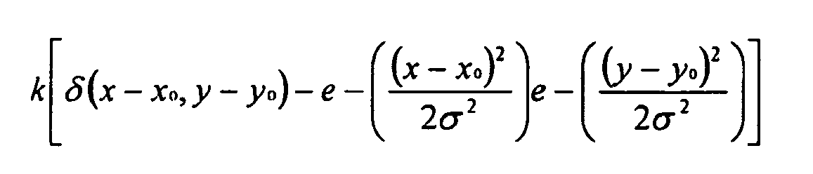
- Method as defined in any one of claims 18 to 20, in which the composite error map generation step includes the steps of:generating a weighted rendering device error map from the rendering device error map by a multiplier (66) and a weighted neighborhood error map from the neighborhood error map by a multiplier (67), both from a weighting value [λ, 1-λ); andgenerating said composite error map from the weighted rendering device error map and the weighted neighborhood error map, in which the weighting value (λ, 1-λ) is preferably selectable by an operator.
- Method according to claim 18, comprising the steps of:generating a plurality of optimized stochastic patterns each from a respective seed stochastic pattern by a pattern optimizer section (41), at least some of the optimized stochastic patterns each being generated from a said respective seed stochastic pattern and a previously-generated optimized stochastic pattern to thereby provide that the optimized stochastic pattern so generated, when tiled with others of the optimized stochastic patterns, will have optimal visual tiling characteristics proximate their respective edges; andgenerating the stochastic threshold arrays from the optimized stochastic patterns by a stochastic threshold array generator (43).
Applications Claiming Priority (3)
| Application Number | Priority Date | Filing Date | Title |
|---|---|---|---|
| US427880 | 1989-10-27 | ||
| US08/427,880 US5745660A (en) | 1995-04-26 | 1995-04-26 | Image rendering system and method for generating stochastic threshold arrays for use therewith |
| EP96910553A EP0768001B1 (en) | 1995-04-26 | 1996-03-22 | Image rendering system and method for generating stochastic threshold array(s) for use therewith |
Related Parent Applications (2)
| Application Number | Title | Priority Date | Filing Date |
|---|---|---|---|
| EP96910553A Division EP0768001B1 (en) | 1995-04-26 | 1996-03-22 | Image rendering system and method for generating stochastic threshold array(s) for use therewith |
| EP96910553.5 Division | 1996-10-31 |
Publications (2)
| Publication Number | Publication Date |
|---|---|
| EP1168820A1 EP1168820A1 (en) | 2002-01-02 |
| EP1168820B1 true EP1168820B1 (en) | 2008-06-25 |
Family
ID=23696669
Family Applications (2)
| Application Number | Title | Priority Date | Filing Date |
|---|---|---|---|
| EP96910553A Expired - Lifetime EP0768001B1 (en) | 1995-04-26 | 1996-03-22 | Image rendering system and method for generating stochastic threshold array(s) for use therewith |
| EP01119962A Expired - Lifetime EP1168820B1 (en) | 1995-04-26 | 1996-03-22 | Stochastic threshold array generating system and method for generating an error map for image rendering |
Family Applications Before (1)
| Application Number | Title | Priority Date | Filing Date |
|---|---|---|---|
| EP96910553A Expired - Lifetime EP0768001B1 (en) | 1995-04-26 | 1996-03-22 | Image rendering system and method for generating stochastic threshold array(s) for use therewith |
Country Status (7)
| Country | Link |
|---|---|
| US (1) | US5745660A (en) |
| EP (2) | EP0768001B1 (en) |
| JP (1) | JP3798021B2 (en) |
| KR (1) | KR100280909B1 (en) |
| CA (1) | CA2192102C (en) |
| DE (2) | DE69620969T2 (en) |
| WO (1) | WO1996034487A1 (en) |
Families Citing this family (108)
| Publication number | Priority date | Publication date | Assignee | Title |
|---|---|---|---|---|
| JPH1075375A (en) * | 1996-05-20 | 1998-03-17 | Fuji Xerox Co Ltd | Image processing apparatus, image processing system, and image processing screen generation method |
| JP3779406B2 (en) * | 1996-11-20 | 2006-05-31 | 松下電器産業株式会社 | Image processing apparatus and image processing method |
| US6020978A (en) * | 1997-09-30 | 2000-02-01 | Lexmark International, Inc. | Method and apparatus for color halftoning using interlocked threshold arrays |
| US6356363B1 (en) | 1997-09-30 | 2002-03-12 | Lexmark International, Inc. | Method for halftoning using interlocked threshold arrays or interlocked dot profiles |
| US6014500A (en) * | 1998-06-01 | 2000-01-11 | Xerox Corporation | Stochastic halftoning screening method |
| US20020071140A1 (en) * | 1998-06-03 | 2002-06-13 | Takashi Suzuki | Threshold matrix, and method and apparatus of reproducing gray levels using threshold matrix |
| US6433891B1 (en) * | 1998-12-14 | 2002-08-13 | Oak Technology, Inc. | Stochastic screening method with dot pattern regularity control and dot growth |
| US6304337B1 (en) | 1998-12-21 | 2001-10-16 | Lexmark International, Inc. | Stochastic method of enlarging a visual image |
| US6115031A (en) * | 1999-04-23 | 2000-09-05 | Lexmark International, Inc. | Method of converting color values |
| US6754375B1 (en) * | 1999-07-16 | 2004-06-22 | Packard Bioscience Company | Method and system for interactively developing at least one grid pattern and computer-readable storage medium having a program for executing the method |
| JP2001326817A (en) * | 2000-05-15 | 2001-11-22 | Matsushita Electric Ind Co Ltd | Image processing device |
| US6829063B1 (en) | 2000-06-14 | 2004-12-07 | Hewlett-Packard Development Company, L.P. | Method for designing sets of color matrices that tile together |
| US6867884B1 (en) | 2000-07-07 | 2005-03-15 | Kodak Polychrome Graphics, Llc | Halftone dot placement for multi-color images |
| EP1323013A2 (en) * | 2000-08-24 | 2003-07-02 | Immersive Technologies LLC | Computerized image system |
| US6710778B2 (en) | 2001-02-12 | 2004-03-23 | Lexmark International, Inc. | Method for halftoning using a difference weighting function |
| CN100385908C (en) * | 2001-09-21 | 2008-04-30 | 株式会社理光 | Gradation reproduction method, image processing method, image processing device, image forming device |
| US7420709B2 (en) | 2003-04-30 | 2008-09-02 | Hewlett-Packard Development Company, L.P. | Dither matrix generation |
| US7327898B2 (en) * | 2003-07-01 | 2008-02-05 | Xerox Corporation | Reducing boundary effects for images with screen patterns |
| CA2443206A1 (en) | 2003-09-23 | 2005-03-23 | Ignis Innovation Inc. | Amoled display backplanes - pixel driver circuits, array architecture, and external compensation |
| DE10358313B4 (en) * | 2003-12-11 | 2015-10-22 | Bayerische Motoren Werke Aktiengesellschaft | Method for producing a graphic element |
| CA2472671A1 (en) | 2004-06-29 | 2005-12-29 | Ignis Innovation Inc. | Voltage-programming scheme for current-driven amoled displays |
| EP1626568A1 (en) * | 2004-08-12 | 2006-02-15 | Toshiba Corporation | Color and density calibration of color printers, halftone super-cell optimization for artifact reduction, and printer profile mapping of input primaries to output primaries |
| CA2490858A1 (en) | 2004-12-07 | 2006-06-07 | Ignis Innovation Inc. | Driving method for compensated voltage-programming of amoled displays |
| US9275579B2 (en) | 2004-12-15 | 2016-03-01 | Ignis Innovation Inc. | System and methods for extraction of threshold and mobility parameters in AMOLED displays |
| US9171500B2 (en) | 2011-05-20 | 2015-10-27 | Ignis Innovation Inc. | System and methods for extraction of parasitic parameters in AMOLED displays |
| US10012678B2 (en) | 2004-12-15 | 2018-07-03 | Ignis Innovation Inc. | Method and system for programming, calibrating and/or compensating, and driving an LED display |
| US10013907B2 (en) | 2004-12-15 | 2018-07-03 | Ignis Innovation Inc. | Method and system for programming, calibrating and/or compensating, and driving an LED display |
| US9280933B2 (en) | 2004-12-15 | 2016-03-08 | Ignis Innovation Inc. | System and methods for extraction of threshold and mobility parameters in AMOLED displays |
| US20140111567A1 (en) | 2005-04-12 | 2014-04-24 | Ignis Innovation Inc. | System and method for compensation of non-uniformities in light emitting device displays |
| TWI402790B (en) | 2004-12-15 | 2013-07-21 | 伊格尼斯創新股份有限公司 | Method and system for programming, calibrating and driving a light-emitting element display |
| US9799246B2 (en) | 2011-05-20 | 2017-10-24 | Ignis Innovation Inc. | System and methods for extraction of threshold and mobility parameters in AMOLED displays |
| US8599191B2 (en) | 2011-05-20 | 2013-12-03 | Ignis Innovation Inc. | System and methods for extraction of threshold and mobility parameters in AMOLED displays |
| US8576217B2 (en) | 2011-05-20 | 2013-11-05 | Ignis Innovation Inc. | System and methods for extraction of threshold and mobility parameters in AMOLED displays |
| CA2496642A1 (en) | 2005-02-10 | 2006-08-10 | Ignis Innovation Inc. | Fast settling time driving method for organic light-emitting diode (oled) displays based on current programming |
| US7852298B2 (en) * | 2005-06-08 | 2010-12-14 | Ignis Innovation Inc. | Method and system for driving a light emitting device display |
| US7724981B2 (en) * | 2005-07-21 | 2010-05-25 | Ancestry.Com Operations Inc. | Adaptive contrast control systems and methods |
| CA2518276A1 (en) | 2005-09-13 | 2007-03-13 | Ignis Innovation Inc. | Compensation technique for luminance degradation in electro-luminance devices |
| EP2458579B1 (en) | 2006-01-09 | 2017-09-20 | Ignis Innovation Inc. | Method and system for driving an active matrix display circuit |
| US9269322B2 (en) | 2006-01-09 | 2016-02-23 | Ignis Innovation Inc. | Method and system for driving an active matrix display circuit |
| US9489891B2 (en) | 2006-01-09 | 2016-11-08 | Ignis Innovation Inc. | Method and system for driving an active matrix display circuit |
| TW200746022A (en) | 2006-04-19 | 2007-12-16 | Ignis Innovation Inc | Stable driving scheme for active matrix displays |
| CA2556961A1 (en) | 2006-08-15 | 2008-02-15 | Ignis Innovation Inc. | Oled compensation technique based on oled capacitance |
| US20090034008A1 (en) * | 2007-08-03 | 2009-02-05 | Lawrence Croft | Method for generating stochastic dither matrix |
| US20090034006A1 (en) * | 2007-08-03 | 2009-02-05 | Blondal Daniel J | Stochastic halftone images based on screening parameters |
| WO2009127065A1 (en) | 2008-04-18 | 2009-10-22 | Ignis Innovation Inc. | System and driving method for light emitting device display |
| CA2637343A1 (en) | 2008-07-29 | 2010-01-29 | Ignis Innovation Inc. | Improving the display source driver |
| US8282182B2 (en) * | 2008-08-22 | 2012-10-09 | Ricoh Production Print Solutions LLC | Correction of print engine artifacts using an iterative halftoning search algorithm |
| US9370075B2 (en) | 2008-12-09 | 2016-06-14 | Ignis Innovation Inc. | System and method for fast compensation programming of pixels in a display |
| CA2688870A1 (en) | 2009-11-30 | 2011-05-30 | Ignis Innovation Inc. | Methode and techniques for improving display uniformity |
| US9311859B2 (en) | 2009-11-30 | 2016-04-12 | Ignis Innovation Inc. | Resetting cycle for aging compensation in AMOLED displays |
| US9384698B2 (en) | 2009-11-30 | 2016-07-05 | Ignis Innovation Inc. | System and methods for aging compensation in AMOLED displays |
| CA2669367A1 (en) | 2009-06-16 | 2010-12-16 | Ignis Innovation Inc | Compensation technique for color shift in displays |
| US10319307B2 (en) | 2009-06-16 | 2019-06-11 | Ignis Innovation Inc. | Display system with compensation techniques and/or shared level resources |
| US8283967B2 (en) | 2009-11-12 | 2012-10-09 | Ignis Innovation Inc. | Stable current source for system integration to display substrate |
| US10996258B2 (en) | 2009-11-30 | 2021-05-04 | Ignis Innovation Inc. | Defect detection and correction of pixel circuits for AMOLED displays |
| US10867536B2 (en) | 2013-04-22 | 2020-12-15 | Ignis Innovation Inc. | Inspection system for OLED display panels |
| US8803417B2 (en) | 2009-12-01 | 2014-08-12 | Ignis Innovation Inc. | High resolution pixel architecture |
| CA2687631A1 (en) | 2009-12-06 | 2011-06-06 | Ignis Innovation Inc | Low power driving scheme for display applications |
| US9881532B2 (en) | 2010-02-04 | 2018-01-30 | Ignis Innovation Inc. | System and method for extracting correlation curves for an organic light emitting device |
| US10176736B2 (en) | 2010-02-04 | 2019-01-08 | Ignis Innovation Inc. | System and methods for extracting correlation curves for an organic light emitting device |
| CA2692097A1 (en) | 2010-02-04 | 2011-08-04 | Ignis Innovation Inc. | Extracting correlation curves for light emitting device |
| US20140313111A1 (en) | 2010-02-04 | 2014-10-23 | Ignis Innovation Inc. | System and methods for extracting correlation curves for an organic light emitting device |
| US10163401B2 (en) | 2010-02-04 | 2018-12-25 | Ignis Innovation Inc. | System and methods for extracting correlation curves for an organic light emitting device |
| US10089921B2 (en) | 2010-02-04 | 2018-10-02 | Ignis Innovation Inc. | System and methods for extracting correlation curves for an organic light emitting device |
| CA2696778A1 (en) * | 2010-03-17 | 2011-09-17 | Ignis Innovation Inc. | Lifetime, uniformity, parameter extraction methods |
| US8907991B2 (en) | 2010-12-02 | 2014-12-09 | Ignis Innovation Inc. | System and methods for thermal compensation in AMOLED displays |
| US8467099B2 (en) * | 2011-05-16 | 2013-06-18 | Xerox Corporation | Directional halftone method with enhanced edge and detail rendition |
| US20140368491A1 (en) | 2013-03-08 | 2014-12-18 | Ignis Innovation Inc. | Pixel circuits for amoled displays |
| US9351368B2 (en) | 2013-03-08 | 2016-05-24 | Ignis Innovation Inc. | Pixel circuits for AMOLED displays |
| US9886899B2 (en) | 2011-05-17 | 2018-02-06 | Ignis Innovation Inc. | Pixel Circuits for AMOLED displays |
| US9530349B2 (en) | 2011-05-20 | 2016-12-27 | Ignis Innovations Inc. | Charged-based compensation and parameter extraction in AMOLED displays |
| US9466240B2 (en) | 2011-05-26 | 2016-10-11 | Ignis Innovation Inc. | Adaptive feedback system for compensating for aging pixel areas with enhanced estimation speed |
| WO2012164475A2 (en) | 2011-05-27 | 2012-12-06 | Ignis Innovation Inc. | Systems and methods for aging compensation in amoled displays |
| WO2012164474A2 (en) | 2011-05-28 | 2012-12-06 | Ignis Innovation Inc. | System and method for fast compensation programming of pixels in a display |
| US10089924B2 (en) | 2011-11-29 | 2018-10-02 | Ignis Innovation Inc. | Structural and low-frequency non-uniformity compensation |
| US9324268B2 (en) | 2013-03-15 | 2016-04-26 | Ignis Innovation Inc. | Amoled displays with multiple readout circuits |
| US8937632B2 (en) | 2012-02-03 | 2015-01-20 | Ignis Innovation Inc. | Driving system for active-matrix displays |
| KR101282700B1 (en) * | 2012-03-12 | 2013-07-05 | 한국과학기술원 | Noise reduction method for stochastic rendering image |
| US9747834B2 (en) | 2012-05-11 | 2017-08-29 | Ignis Innovation Inc. | Pixel circuits including feedback capacitors and reset capacitors, and display systems therefore |
| US8922544B2 (en) | 2012-05-23 | 2014-12-30 | Ignis Innovation Inc. | Display systems with compensation for line propagation delay |
| JP6296726B2 (en) * | 2012-11-16 | 2018-03-20 | キヤノン株式会社 | Dither pattern creation method and image processing apparatus |
| US9336717B2 (en) | 2012-12-11 | 2016-05-10 | Ignis Innovation Inc. | Pixel circuits for AMOLED displays |
| US9786223B2 (en) | 2012-12-11 | 2017-10-10 | Ignis Innovation Inc. | Pixel circuits for AMOLED displays |
| US9830857B2 (en) | 2013-01-14 | 2017-11-28 | Ignis Innovation Inc. | Cleaning common unwanted signals from pixel measurements in emissive displays |
| WO2014108879A1 (en) | 2013-01-14 | 2014-07-17 | Ignis Innovation Inc. | Driving scheme for emissive displays providing compensation for driving transistor variations |
| WO2014124298A1 (en) * | 2013-02-07 | 2014-08-14 | Nancy Burson | Pattern generation for viewing data in multiple directions |
| US9721505B2 (en) | 2013-03-08 | 2017-08-01 | Ignis Innovation Inc. | Pixel circuits for AMOLED displays |
| CA2894717A1 (en) | 2015-06-19 | 2016-12-19 | Ignis Innovation Inc. | Optoelectronic device characterization in array with shared sense line |
| EP2779147B1 (en) | 2013-03-14 | 2016-03-02 | Ignis Innovation Inc. | Re-interpolation with edge detection for extracting an aging pattern for AMOLED displays |
| WO2015022626A1 (en) | 2013-08-12 | 2015-02-19 | Ignis Innovation Inc. | Compensation accuracy |
| US9741282B2 (en) | 2013-12-06 | 2017-08-22 | Ignis Innovation Inc. | OLED display system and method |
| US9761170B2 (en) | 2013-12-06 | 2017-09-12 | Ignis Innovation Inc. | Correction for localized phenomena in an image array |
| US9502653B2 (en) | 2013-12-25 | 2016-11-22 | Ignis Innovation Inc. | Electrode contacts |
| US10192479B2 (en) | 2014-04-08 | 2019-01-29 | Ignis Innovation Inc. | Display system using system level resources to calculate compensation parameters for a display module in a portable device |
| CA2873476A1 (en) | 2014-12-08 | 2016-06-08 | Ignis Innovation Inc. | Smart-pixel display architecture |
| CA2879462A1 (en) | 2015-01-23 | 2016-07-23 | Ignis Innovation Inc. | Compensation for color variation in emissive devices |
| CA2886862A1 (en) | 2015-04-01 | 2016-10-01 | Ignis Innovation Inc. | Adjusting display brightness for avoiding overheating and/or accelerated aging |
| CA2889870A1 (en) | 2015-05-04 | 2016-11-04 | Ignis Innovation Inc. | Optical feedback system |
| CA2892714A1 (en) | 2015-05-27 | 2016-11-27 | Ignis Innovation Inc | Memory bandwidth reduction in compensation system |
| CA2898282A1 (en) | 2015-07-24 | 2017-01-24 | Ignis Innovation Inc. | Hybrid calibration of current sources for current biased voltage progra mmed (cbvp) displays |
| US10657895B2 (en) | 2015-07-24 | 2020-05-19 | Ignis Innovation Inc. | Pixels and reference circuits and timing techniques |
| US10373554B2 (en) | 2015-07-24 | 2019-08-06 | Ignis Innovation Inc. | Pixels and reference circuits and timing techniques |
| CA2900170A1 (en) | 2015-08-07 | 2017-02-07 | Gholamreza Chaji | Calibration of pixel based on improved reference values |
| CA2908285A1 (en) | 2015-10-14 | 2017-04-14 | Ignis Innovation Inc. | Driver with multiple color pixel structure |
| JP2017184197A (en) * | 2016-03-31 | 2017-10-05 | 船井電機株式会社 | Printer |
| KR20250051134A (en) | 2019-05-21 | 2025-04-16 | 에이에스엠엘 네델란즈 비.브이. | Method for determining stochastic variation associated with desired pattern |
| US11758074B2 (en) * | 2021-03-05 | 2023-09-12 | Ricoh Company, Ltd. | Color uniformity compensation mechanism |
| US11734536B2 (en) * | 2021-03-05 | 2023-08-22 | Ricoh Company, Ltd. | Color uniformity compensation mechanism |
Family Cites Families (5)
| Publication number | Priority date | Publication date | Assignee | Title |
|---|---|---|---|---|
| US4734770A (en) * | 1986-03-13 | 1988-03-29 | Hitachi, Ltd. | Image data processing method and device therefor |
| US5214517A (en) * | 1990-02-07 | 1993-05-25 | Eastman Kodak Company | Digital halftoning with correlated minimum visual modulation patterns |
| EP0472764B1 (en) * | 1990-08-30 | 1996-03-06 | Deutsche ITT Industries GmbH | Method for reducing colour noise of a television signal |
| US5111310A (en) * | 1990-12-04 | 1992-05-05 | Research Technologies Corporation, Inc. | Method and apparatus for halftone rendering of a gray scale image using a blue noise mask |
| US5394250A (en) * | 1991-03-10 | 1995-02-28 | Canon Kabushiki Kaisha | Image processing capable of handling multi-level image data without deterioration of image quality in highlight areas |
-
1995
- 1995-04-26 US US08/427,880 patent/US5745660A/en not_active Expired - Lifetime
-
1996
- 1996-03-22 KR KR1019960707455A patent/KR100280909B1/en not_active Expired - Lifetime
- 1996-03-22 WO PCT/US1996/004057 patent/WO1996034487A1/en not_active Ceased
- 1996-03-22 DE DE69620969T patent/DE69620969T2/en not_active Expired - Lifetime
- 1996-03-22 CA CA002192102A patent/CA2192102C/en not_active Expired - Lifetime
- 1996-03-22 EP EP96910553A patent/EP0768001B1/en not_active Expired - Lifetime
- 1996-03-22 EP EP01119962A patent/EP1168820B1/en not_active Expired - Lifetime
- 1996-03-22 JP JP53251496A patent/JP3798021B2/en not_active Expired - Lifetime
- 1996-03-22 DE DE69637573T patent/DE69637573D1/en not_active Expired - Lifetime
Non-Patent Citations (1)
| Title |
|---|
| ULICHNEY R.: "The void-and-cluster method for dither array generation", PROCEEDINGS OF THE SPIE, vol. 1913, 1993, BELLINGHAM, VA, US, pages 332 - 343, XP000945367, ISSN: 0277-786X * |
Also Published As
| Publication number | Publication date |
|---|---|
| DE69637573D1 (en) | 2008-08-07 |
| KR970704289A (en) | 1997-08-09 |
| DE69620969T2 (en) | 2002-11-28 |
| US5745660A (en) | 1998-04-28 |
| EP1168820A1 (en) | 2002-01-02 |
| EP0768001A1 (en) | 1997-04-16 |
| WO1996034487A1 (en) | 1996-10-31 |
| JP3798021B2 (en) | 2006-07-19 |
| EP0768001B1 (en) | 2002-05-02 |
| CA2192102A1 (en) | 1996-10-31 |
| CA2192102C (en) | 1999-11-16 |
| DE69620969D1 (en) | 2002-06-06 |
| KR100280909B1 (en) | 2001-02-01 |
| JPH10502793A (en) | 1998-03-10 |
Similar Documents
| Publication | Publication Date | Title |
|---|---|---|
| EP0768001B1 (en) | Image rendering system and method for generating stochastic threshold array(s) for use therewith | |
| US5317418A (en) | Halftone images using special filters | |
| US4654721A (en) | System for reproducing multi-level digital images on a bi-level printer of fixed dot size | |
| EP0812102B1 (en) | Method for halftoning a multi-channel digital color image | |
| EP0560872B1 (en) | Method and apparatus for halftone rendering of a gray scale image using a blue noise mask | |
| EP1392048B1 (en) | Halftone dot-growth technique based on morphological filtering | |
| EP0493101B1 (en) | Image conversion | |
| US5341228A (en) | Method and apparatus for halftone rendering of a gray scale image using a blue noise mask | |
| US5473439A (en) | Model-based halftoning of color images | |
| Allebach | DBS: retrospective and future directions | |
| EP0591274B1 (en) | Improved error diffusion system | |
| US5946452A (en) | Partially correlated minimum visibility halftone patterns for digital printers | |
| US5515456A (en) | Process for providing digital halftone image with random error diffusion, color correction and enlargement | |
| JPH08228287A (en) | Method and apparatus for minimizing worms in images produced by error diffusion halftone data used in ink reduction processing | |
| US5557709A (en) | Method and apparatus for dither array generation to reduce artifacts in halftoned images | |
| EP1271927A2 (en) | Method for halftoning a multi-channel digital color image having at least one group of similar color channels | |
| EP0631428A2 (en) | Pixel error diffusion method | |
| EP0977424B1 (en) | Halftone printing using donut filters | |
| US6704123B1 (en) | Method for applying tonal correction to a binary halftone image | |
| US6122407A (en) | Method and apparatus for producing threshold arrays using variance minimization and sparse image calculations | |
| US6025930A (en) | Multicell clustered mask with blue noise adjustments | |
| US5499305A (en) | Method and apparatus for coalescing a grayscale image and rendering the coalesced grayscale image as a binary image | |
| JPH0622123A (en) | Halftone mask for digital image and method of making the same | |
| Yu et al. | Digital multitoning with overmodulation for smooth texture transition | |
| US5764810A (en) | Screenless conversion of continuous tone images with alterable dot spacing patterns |
Legal Events
| Date | Code | Title | Description |
|---|---|---|---|
| PUAI | Public reference made under article 153(3) epc to a published international application that has entered the european phase |
Free format text: ORIGINAL CODE: 0009012 |
|
| 17P | Request for examination filed |
Effective date: 20010817 |
|
| AC | Divisional application: reference to earlier application |
Ref document number: 768001 Country of ref document: EP |
|
| AK | Designated contracting states |
Kind code of ref document: A1 Designated state(s): DE FR GB IT |
|
| AKX | Designation fees paid |
Free format text: DE FR GB IT |
|
| RAP1 | Party data changed (applicant data changed or rights of an application transferred) |
Owner name: POLAROID CORPORATION |
|
| 17Q | First examination report despatched |
Effective date: 20030625 |
|
| RAP1 | Party data changed (applicant data changed or rights of an application transferred) |
Owner name: SENSHIN CAPITAL, LLC |
|
| RTI1 | Title (correction) |
Free format text: STOCHASTIC THRESHOLD ARRAY GENERATING SYSTEM AND METHOD FOR GENERATING AN ERROR MAP FOR IMAGE RENDERING |
|
| GRAP | Despatch of communication of intention to grant a patent |
Free format text: ORIGINAL CODE: EPIDOSNIGR1 |
|
| GRAS | Grant fee paid |
Free format text: ORIGINAL CODE: EPIDOSNIGR3 |
|
| GRAA | (expected) grant |
Free format text: ORIGINAL CODE: 0009210 |
|
| AC | Divisional application: reference to earlier application |
Ref document number: 0768001 Country of ref document: EP Kind code of ref document: P |
|
| AK | Designated contracting states |
Kind code of ref document: B1 Designated state(s): DE FR GB IT |
|
| REG | Reference to a national code |
Ref country code: GB Ref legal event code: FG4D |
|
| REF | Corresponds to: |
Ref document number: 69637573 Country of ref document: DE Date of ref document: 20080807 Kind code of ref document: P |
|
| PLBE | No opposition filed within time limit |
Free format text: ORIGINAL CODE: 0009261 |
|
| STAA | Information on the status of an ep patent application or granted ep patent |
Free format text: STATUS: NO OPPOSITION FILED WITHIN TIME LIMIT |
|
| 26N | No opposition filed |
Effective date: 20090326 |
|
| PG25 | Lapsed in a contracting state [announced via postgrant information from national office to epo] |
Ref country code: IT Free format text: LAPSE BECAUSE OF FAILURE TO SUBMIT A TRANSLATION OF THE DESCRIPTION OR TO PAY THE FEE WITHIN THE PRESCRIBED TIME-LIMIT Effective date: 20080625 |
|
| REG | Reference to a national code |
Ref country code: FR Ref legal event code: PLFP Year of fee payment: 20 |
|
| PGFP | Annual fee paid to national office [announced via postgrant information from national office to epo] |
Ref country code: FR Payment date: 20150224 Year of fee payment: 20 Ref country code: GB Payment date: 20150224 Year of fee payment: 20 |
|
| PGFP | Annual fee paid to national office [announced via postgrant information from national office to epo] |
Ref country code: DE Payment date: 20150331 Year of fee payment: 20 |
|
| REG | Reference to a national code |
Ref country code: DE Ref legal event code: R071 Ref document number: 69637573 Country of ref document: DE |
|
| REG | Reference to a national code |
Ref country code: GB Ref legal event code: PE20 Expiry date: 20160321 |
|
| PG25 | Lapsed in a contracting state [announced via postgrant information from national office to epo] |
Ref country code: GB Free format text: LAPSE BECAUSE OF EXPIRATION OF PROTECTION Effective date: 20160321 |