EP0472764B1 - Method for reducing colour noise of a television signal - Google Patents
Method for reducing colour noise of a television signal Download PDFInfo
- Publication number
- EP0472764B1 EP0472764B1 EP90116639A EP90116639A EP0472764B1 EP 0472764 B1 EP0472764 B1 EP 0472764B1 EP 90116639 A EP90116639 A EP 90116639A EP 90116639 A EP90116639 A EP 90116639A EP 0472764 B1 EP0472764 B1 EP 0472764B1
- Authority
- EP
- European Patent Office
- Prior art keywords
- signal
- component
- chrominance
- noise
- line
- Prior art date
- Legal status (The legal status is an assumption and is not a legal conclusion. Google has not performed a legal analysis and makes no representation as to the accuracy of the status listed.)
- Expired - Lifetime
Links
- 238000000034 method Methods 0.000 title claims description 32
- 238000012545 processing Methods 0.000 claims description 55
- 238000012937 correction Methods 0.000 claims description 43
- 230000009467 reduction Effects 0.000 claims description 11
- 230000002596 correlated effect Effects 0.000 claims description 8
- 230000000875 corresponding effect Effects 0.000 claims description 7
- 238000012546 transfer Methods 0.000 claims description 6
- 230000004048 modification Effects 0.000 claims description 5
- 238000012986 modification Methods 0.000 claims description 5
- 238000001914 filtration Methods 0.000 claims description 4
- 230000001419 dependent effect Effects 0.000 claims description 3
- 238000009795 derivation Methods 0.000 claims description 3
- 238000004364 calculation method Methods 0.000 claims description 2
- 238000009826 distribution Methods 0.000 claims description 2
- 230000003595 spectral effect Effects 0.000 claims description 2
- 230000006870 function Effects 0.000 description 9
- 230000008901 benefit Effects 0.000 description 6
- 230000000694 effects Effects 0.000 description 5
- 238000011161 development Methods 0.000 description 4
- 230000018109 developmental process Effects 0.000 description 4
- 238000004519 manufacturing process Methods 0.000 description 4
- 238000013461 design Methods 0.000 description 3
- 238000010586 diagram Methods 0.000 description 3
- 230000008030 elimination Effects 0.000 description 3
- 238000003379 elimination reaction Methods 0.000 description 3
- 230000008569 process Effects 0.000 description 3
- 230000001105 regulatory effect Effects 0.000 description 3
- 238000005070 sampling Methods 0.000 description 3
- 230000002411 adverse Effects 0.000 description 2
- 230000002238 attenuated effect Effects 0.000 description 2
- 230000006399 behavior Effects 0.000 description 2
- 230000005540 biological transmission Effects 0.000 description 2
- 230000001276 controlling effect Effects 0.000 description 2
- 238000013016 damping Methods 0.000 description 2
- 230000006866 deterioration Effects 0.000 description 2
- 238000011144 upstream manufacturing Methods 0.000 description 2
- 241000283986 Lepus Species 0.000 description 1
- 108010076504 Protein Sorting Signals Proteins 0.000 description 1
- 230000004913 activation Effects 0.000 description 1
- 230000015572 biosynthetic process Effects 0.000 description 1
- 230000008859 change Effects 0.000 description 1
- 230000009849 deactivation Effects 0.000 description 1
- 230000007423 decrease Effects 0.000 description 1
- 230000006872 improvement Effects 0.000 description 1
- 238000009877 rendering Methods 0.000 description 1
- 238000003860 storage Methods 0.000 description 1
- 230000007704 transition Effects 0.000 description 1
Images


Classifications
-
- H—ELECTRICITY
- H04—ELECTRIC COMMUNICATION TECHNIQUE
- H04N—PICTORIAL COMMUNICATION, e.g. TELEVISION
- H04N9/00—Details of colour television systems
- H04N9/64—Circuits for processing colour signals
- H04N9/646—Circuits for processing colour signals for image enhancement, e.g. vertical detail restoration, cross-colour elimination, contour correction, chrominance trapping filters
-
- H—ELECTRICITY
- H04—ELECTRIC COMMUNICATION TECHNIQUE
- H04N—PICTORIAL COMMUNICATION, e.g. TELEVISION
- H04N11/00—Colour television systems
- H04N11/04—Colour television systems using pulse code modulation
- H04N11/042—Codec means
- H04N11/048—Sub-Nyquist sampling
-
- H—ELECTRICITY
- H04—ELECTRIC COMMUNICATION TECHNIQUE
- H04N—PICTORIAL COMMUNICATION, e.g. TELEVISION
- H04N11/00—Colour television systems
- H04N11/06—Transmission systems characterised by the manner in which the individual colour picture signal components are combined
- H04N11/12—Transmission systems characterised by the manner in which the individual colour picture signal components are combined using simultaneous signals only
- H04N11/14—Transmission systems characterised by the manner in which the individual colour picture signal components are combined using simultaneous signals only in which one signal, modulated in phase and amplitude, conveys colour information and a second signal conveys brightness information, e.g. NTSC-system
- H04N11/16—Transmission systems characterised by the manner in which the individual colour picture signal components are combined using simultaneous signals only in which one signal, modulated in phase and amplitude, conveys colour information and a second signal conveys brightness information, e.g. NTSC-system the chrominance signal alternating in phase, e.g. PAL-system
Definitions
- the invention relates to a method for reducing the color noise of the chrominance signals of a television picture by means of a vertical digital filter, in which the chrominance signal of each line, the color component of which is superimposed on a stochastically spectrally distributed noise component, and a noise-reduced reference obtained from the chrominance signals of the vertically preceding lines.
- Chrominance signal a differential signal is derived, the frequency and amplitude of which is determined by the noise component of this line and by the correlation of the color component of this line with the color components of the vertically preceding lines, and in which the derivation of the noise-reduced used in the calculation of the difference signal of the vertically subsequent line
- Reference chrominance signal is carried out by recursive signal processing operations of the digital filter, in that this noise-reduced reference chrominance signal is derived from the difference signal evaluated with a first correction factor signal and is formed from the chrominance signal of this line, and in which the noise component of the chrominance signal of this line is reduced by transversal signal processing operations, in that a noise-reduced chrominance signal is formed by subtracting the difference signal evaluated with a second correction factor from the chrominance signal of this line, and a device for carrying out the method.
- HQ filter High Quality
- the known method works reasonably satisfactorily for well-correlated chrominance signals of vertically successive lines: in this case, the frequency and the amplitude of the difference signal formed from the chrominance signal of the line and from the reference chrominance signal of the vertically preceding lines is essentially determined by the noise component of the line to be processed certainly.
- the difference signal has a low-frequency character and has only a small amplitude, so that this signal without Modifications in the recursive signal processing operations for obtaining the reference chrominance signal for the vertically following line and in the transverse signal processing operations for reducing the color noise of the line to be processed can be made without any modifications.
- a further noise elimination circuit for digital color television signals in which the noise signal determined by difference formation is passed before further processing via a limiter which, at high noise amplitudes, which can also result from color signal jumps, the effect of the noise filter reduced.
- the respective noise reference variable is determined within the respective field by evaluating the correlation of the color signals between the lines of the video signal in the vertical direction. For this purpose, the difference from the color signals of the current and the previous line is formed pixel by pixel in a subtractor, the value of which is modified for further signal processing by means of a limiter with a non-linear characteristic.
- the known method has the disadvantage that it only leads to unsatisfactory results if the chrominance signals of vertically successive lines are not correspondingly correlated. This is always the case if there are color jumps between two closely consecutive lines in the television picture: In this case, the difference signal contains not only the noise component of the line but also high-frequency components with a large signal amplitude, which result from this color jump. However, such a high-frequency differential signal with a large signal amplitude must not be included in the recursive filtering, since otherwise a jump in color will occur.
- the analog circuit device used to carry out the method also has the disadvantage that a particularly expensive and complex design is required for processing PAL color television signals.
- the line-alternating phase of the (RY) component of a PAL chrominance signal means that two delay lines are required in the known HQ filters.
- such a delay line represents a particularly expensive component, so that the known devices can only be implemented in a particularly disadvantageous manner at relatively high costs.
- a further disadvantage of the known device is that it cannot be used to correct special color disturbances which occur in some modes of operation of a video recorder in the television picture:
- the lines of a field are on track offset from each other on the video tape.
- the video head runs obliquely over the tracks, so that half-line jumps and sign errors of the (RY) component of the PAL chrominance signal can occur in the video signal read.
- a circuit specially designed for this purpose has hitherto been used to correct such interference in the television picture.
- this entails increased production costs for the video recorder, since both a circuit for correcting the color noise and a further circuit for eliminating the color disturbances just mentioned must be present in the video recorder.
- the object of the invention is to develop a method and a device of the type mentioned at the outset in such a way that no blurring of color jumps occurs in the case of vertically uncorrelated chrominance signals.
- the device according to the invention is to be designed in such a way that the correction of half-line jumps and phase errors of a PAL color television signal can also be carried out with only a relatively small additional hardware expenditure.
- the differential signal in the recursive and transverse signal processing operations of one of the digital filters is guided via a limiter by means of digital signal processing, the transfer function of which is defined in such a way that small differential signals are passed through unchanged, but large differential signals are suppressed, with an intermediate range a transition takes place: in the case of an uncorrelated chrominance signals representing vertically consecutive lines, there is therefore an amplitude-dependent damping of the same.
- a difference signal representing correlated chrominance signals of vertically successive lines is transmitted without attenuation.
- the modified difference signal obtained in this way is used in the recursive and in the transverse signal processing operations instead of the original difference signal.
- the method according to the invention has the advantage that an effective reduction or elimination of the color noise of the chrominance signals of a television picture is made possible even with non-correlated or only poorly correlated chrominance signals of vertically successive lines.
- the Measures according to the invention have the effect that no color jumps, that is to say no "color hanging", occur: in the case of a high-frequency difference signal with large signal amplitudes, the same is attenuated, depending on the amplitude of the difference signal, so that the modified difference signal entering the recursive signal processing operations can no longer adversely affect the reference chrominance signal.
- the reference chrominance signal remains essentially unchanged, which ensures the proper functioning of the method according to the invention for reducing the color noise even with uncorrelated chrominance signals of vertically successive lines. In a particularly advantageous manner, this results in a drastic improvement in the color rendering of a television picture.
- This method is carried out according to the invention in a preferred device, in which it is provided in a particularly advantageous manner that an input of the digital filter is connected to a minuend input of a subtractor, and that a subtrahend input of the subtractor is optionally connected to a second register and can optionally be connected to the outputs of a delay device, the length of the delay device being one line of Television picture, and that an output of the subtractor is connected to the input of a limiter, and that the output of the limiter is connected to a first register, the output of which is connected to the input of the delay device, to an input of a multiplier and to an input of a third register and that the output of the multiplier is connected to the input of the second register, and that a multiplier input of the multiplier can be selectively connected via a switch to a first and to a second memory register, in which the first correction factor, the second correction factor and the two values of the correction constants can be stored.
- This preferred device according to the invention is distinguished from the device belonging to the prior art by its particularly simple hardware design. In the known device, two multipliers, three subtractors and six registers are necessary. The preferred device described above now allows the method according to the invention to be carried out with only one multiplier, one subtractor and three registers. This considerable reduction in the number of components lowers the manufacturing costs considerably.
- An advantageous development of the invention provides that a first and a second inverter are provided, which are connected upstream or downstream of the digital filter (HQ filter) according to the invention.
- Such an arrangement of the two inverters has a number of advantages: First, it is particularly easy to process both NTSC color television signals and PAL color television signals in one and the same digital filter: With NTSC signals, filtering can be carried out without modifying the (RY) Component and the (BY) component of the baseband signals of the chrominance signal. In the case of PAL color television signals whose (RY) component has a phase position alternating line by line, the invention provides that this component of the baseband is inverted in every second line of the vertically successive lines.
- the digital filter connected downstream of the first inverter can be designed independently of the (phase) norm of the color television signals to be processed.
- the correction of the line-alternating (RY) components of the PAL color television signals carried out in the first inverter therefore considerably simplifies the hardware structure of the digital filter. It is also particularly advantageous that - in contrast to the known devices for reducing the color noise of a PAl television signal, which require two analog delay lines, only a single delay device, for example a shift register, is required here.
- the delay device of the digital filter is designed in the form of two partial delay devices of equal length.
- This inventive design of the delay device causes only minimal additional costs, but allows both the method for reducing the color noise and the above-mentioned method for correcting playback errors, for example in the search run, to be carried out with a single circuit, with this advantageous development of the invention.
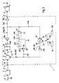
- FIG. 1 shows a vertical digital filter 1 and a first and a second switchable inverter 3 and 4, which are connected upstream or downstream of the digital filter 1.
- the chrominance signal FR to be processed of a line of a television picture is present at an input E of the device.
- This essentially consists of a color component F containing the color information and a (color) noise component R superimposed on the color component F and having a stochastic spectral distribution.
- the chrominance signal FR present at input E was previously digitized by an analog / digital converter (not shown) and separated with a comb filter, not shown, from the color television signal consisting of luminance signal Y and chrominance signal FR.
- this was the (RY) component and a (BY) component in quadrature modulation containing chrominance signal FR demodulated and mixed down into the baseband.
- a sampling frequency which is at least eight times the Nyquist frequency. In practice, this digitization is carried out with a sampling frequency which is the same for all television standards and which is somewhat larger than the bandwidth of the (RY) and (BY) baseband signals (approx. 1 MHz). This oversampling ensures that each of the two components of the chrominance signal FR of a pixel of the television picture is split into a sequence of 1296 sub-signals.
- a digital signal group is formed from eight partial signals each of the (RY) component and the (BY) component of the chrominance signal FR of each pixel of the television picture.
- This grouping of the digitized chrominance signal FR of each pixel of the television picture makes it possible to process the synchronously occurring (RY) and (BY) components of the baseband in a staggered manner, in that only one partial signal of the (RY) and the (BY ) Component of each digital signal group for vertical noise reduction of the segment or pixel determined by the partial signals of this digital signal group. This resulting subsampling of this segment is permitted due to the digitization of the signals with the eight times Nyquist frequency required above.
- the device is thus supplied with a large number of sequentially consecutive, subsampled digital signal groups, each of these groups containing four partial signals of the (RY) component and then four partial signals of the (BY) component serially in time division multiplexing.
- the sampling rate of the effective color cycle compared to the system cycle is therefore one eighth, although the signal processing takes place in the system cycle. This enables multiple use of some functional units.
- chrominance signal of a line means the sequential processing of all subsampled digital signal groups on a line. Accordingly, a vertical correlation of the chrominance signals means the vertical correlation of corresponding digital signal groups.
- the color noise of the chrominance signal FR of each line of the television picture is now reduced in eight cycles of a system clock controlling the digital signal processing of the chrominance branch of the television receiver:
- the chrominance signal FR is passed to an input 3 'of a first inverter 3.
- the first inverter 3 inverts the phase position of the (RY) component of every other line of the vertically successive lines of a television picture.
- This measure has the advantage that the digital filter 1 connected downstream of the first inverter 3 can be designed independently of the norm of the television signals to be processed: the correction of the line-alternating (RY) components of the PAL color television signals carried out in the first inverter 3 simplifies the hardware structure the device considerably.
- a particular advantage here is that - in contrast to the known devices for reducing the color noise in PAL television signals, which require two delay lines - the device described here only requires a single delay device in which the (RY) and (BY ) Components are stored alternately with the system clock.
- the non-alternating (B-Y) component of a PAL color television signal is always unchanged by the first inverter 3, i.e. switched through without inversion of the phase position.
- the (RY) component of the chrominance signal FR passed from an output 3 ′′ of the first inverter 3 to the input 1 ′ of the digital filter becomes a minuend input 6a 'of a first subtractor 6a.
- a reduced-noise reference chrominance signal FK1 which - as will be described in detail below - was obtained from the chrominance signals of one or more vertically preceding lines by recursive signal processing operations.
- a (R-Y) component of the difference signal FD is formed from the (R-Y) component of the chrominance signal FR and from the reference chrominance signal FK1 averaged over a number of vertically preceding lines and thereby reduced in noise.
- This difference signal FD represents the change in the line content between vertically consecutive lines: If the color component F of the chrominance signal FR and the color components of this line of the vertically preceding lines are well correlated, i.e. there are no large color jumps between these lines in the television picture, then the difference signal becomes FD essentially determined by the noise component R of the line to be eliminated.
- the difference signal FD contains not only the noise component R but also other high-frequency components with a large signal amplitude, which result from this color jump.
- a difference signal FD must not be included in the recursive filtering, since otherwise a jump in color will occur. This effect, known as "color hanging", otherwise leads in a particularly disadvantageous manner to a deterioration in the color fidelity of the television picture.
- a limiter 10 is connected downstream of the first subtractor 6a, in which the difference signal FD is processed as follows: With a low-frequency and a small-amplitude difference signal FD - i.e. with well-correlated chrominance signals vertically of successive lines - the limiter 10 passes the difference signal FD unchanged. If, on the other hand, there is an input 6 '''' of the first subtractor 6 connected to the input 10 'of the limiter 10 which represents an uncorrelated chrominance signals and therefore a high-frequency and high-amplitude difference signal FD, this signal is damped or completely suppressed.
- FIG. 2 shows the characteristic of a preferred transfer function of the limiter 10.
- the amplitude of the differential signal FD present at the input 10 ′ of the limiter 10 is plotted on the abscissa of the two-dimensional transmission diagram shown in FIG. 2.
- the ordinate shows the amplitude of a modified difference signal FDM occurring at the output 10 ′′ of the limiter 10. It can be seen that the limiter 10 has a proportional transmission characteristic for small absolute amounts of the differential signal FD:
- the amplitude of the modified differential signal FDM occurring at the output 10 ′′ of the limiter 10 is equal to the amplitude of the differential signal FD.
- the differential signal FD present at the input 10 ' is attenuated:
- the amplitude of the modified differential signal FDM occurring at the output 10' 'of the limiter 10 decreases continuously from the threshold value S (for example linearly) and strives for the value "0" that is reached at the upper threshold S '.
- the amplitude behavior of the transfer function of the limiter 10 shown in FIG. 2 has only an exemplary character. It will be apparent to those skilled in the art how it has to determine the transfer function of the limiter 10 and thus the achievable modification of the difference signal FD, so that the transfer behavior best suited for the respective application can be achieved.
- the limiter 10 allows the difference signal FD to pass essentially unchanged at small amplitudes of the difference signal FD - that is to say with well correlated chrominance signals of vertically successive lines, and that with an uncorrelated chrominance signals representing vertically successive lines, the difference signal FD with large amplitude is damped , the difference signal being completely suppressed above an upper threshold value S '.
- the modified difference signal FDM is stored in a first register 20a.
- the modified difference signal FDM is read out of the first register 20a and passed to an input 30a 'of a first multiplier 30a.
- the modified difference signal FDM with a first correction factor K1 multiplied The definition of the first correction factor K1 will be explained in more detail after the description of the fourth cycle.
- the first correction signal RK1 obtained in this way is stored in a second register 20b connected to an output 30a ′′ of the first multiplier 30a.
- the signal processing of the first clock described above takes place again in the second cycle.
- the (R-Y) component of the chrominance signal of the line to be processed and the noise-reduced reference chrominance signal FK1 are subtracted as described above. This serves to reload the first register 20a with a modified difference signal FDM. This renewed derivation of this difference signal can, however, be omitted if the first register 20a is designed as a so-called multiple-readable register, which retains its memory content beyond the query carried out at the beginning of the second cycle.
- the first correction signal RK1 is read out of the second register 20b and passed to a subtrahend input 6b ′′ of a second subtractor 6b.
- the second subtractor 6b is connected to the (RY) component of the chrominance signal FR.
- the subtraction of the first correction signal RK1 from the (R-Y) component of the chrominance signal FR forms the reference chrominance signal FK1, which is reduced in noise by the first correction factor K1.
- This is stored in a third register 20c connected to an output 6b '' 'of the second subtractor 6b.
- the noise-reduced reference chrominance signal FK1 immediately takes on the value of the new chrominance signal FR after the second subtractor 6b. The annoying blurring of vertical color jumps is avoided in a simple manner.
- the modified difference signal FDM is passed from the first register 20a to an input 30b 'of a second multiplier 30b.
- the modified difference signal FDM is multiplied by a second correction factor K2.
- the second correction factor K2 is - as will be described after the 4th bar - set in a known manner.
- the second correction signal RK2 formed in this way is stored in a fourth register 20d connected to an output 30b ′′ of the second multiplier 30b.
- the noise-reduced reference chrominance signal FK1 is read out from the third register 20c and passed to the input 40 'of a delay line 40.
- the length of the delay line 40 consisting of two partial delay lines 40a and 40b is determined in such a way that the noise-reduced chrominance signal FK1 is present at its output 40 ′′ at the time when the (RY) component of the chrominance signal FR of the vertically following line is applied to the Minuend input 6a 'of the first subtractor 6a arrives: in the case described here, the delay time is therefore exactly the duration of one line.
- the division of the delay line 40 into two equally long partial delay lines 40a and 40b and the function of the signal lines 45 and 46 and the switch 50 is not important for understanding the method for noise reduction. These components of the digital filter 1 are only required in the "color correction" method described below, which is why reference is made to this point to explain its function. This division of the delay line 40 into two is not necessary for noise reduction.
- the second correction signal RK2 is read out of the register 20d and passed to a subtrahend input 6c ′′ of a third subtractor 6c.
- the (R-Y) component of the chrominance signal FR is present at a minuend input 6c 'of the third subtractor 6c.
- the subtraction of these two signals reduces or completely eliminates the noise component R of the (R-Y) component of the chrominance signal FR of the line - corresponding to the second correction signal RK2.
- the noise-reduced (R-Y) component of the noise-reduced chrominance signal FK2 thus formed is stored in a fifth register 20e connected to the output 6c '' 'of the third subtractor 6c.
- the influence of the first and second correction factors K1 and K2 on the method for reducing the color noise of a chrominance signal is known to those skilled in the art from the above Description clearly visible:
- the correction factor K1 assigned to the first multiplier 30a determines the time constant of the recursive branch of the digital filter 1 and thus the number of lines which are used to form the noise-reduced reference chrominance signal FK1.
- the second correction factor K2 assigned to the second multiplier 30b determines the reduction in the color noise component in the transverse branch of the signal processing of the digital filter 1 and thus the noise reduction in the actual output signal.
- the noise-reduced (R-Y) component is passed from the fifth register 20e to a sixth register 20f.
- the (BY) component of the chrominance signal FR at input E is processed analogously to the (RY) component:
- the signal processing of the (BY) component, which takes place in the fifth cycle, is the same as the signal processing of the (RY) component of the first cycle identical.
- the noise-reduced (R-Y) component of the chrominance signal FK2 is read out from the fifth register 20e in the sixth cycle of the signal processing and passed to the second inverter 4. This serves to cancel the modification of the phase position of every second (RY) component of a PAL color television signal carried out in the first inverter 3, so that the noise-reduced (RY) component of the noise-reduced chrominance signal FK2 in one of the respective color television sets at the output A of the device -Normally appropriate way.
- the mode of operation of the second inverter 4 can be seen from the description of the function of the first inverter 3 and therefore need not be repeated at this point.
- the noise-reduced (R-Y) component of the noise-reduced chrominance signal FK2 is present at output A of the device.
- the (BY) component at input E is processed in measures six to eight in the same way as the (RY) component in measures two to four.
- this device can be used in a particularly advantageous manner to carry out a method for correcting half-line color jumps and PAL phase errors which occur in some operating modes of a video recorder due to the system.
- the lines of a field are offset from track to track on the video tape.
- the video head runs obliquely over the tracks of the video tape, so that half-line jumps and / or sign errors of the (R-Y) component occur in the video signal read out of a few lines of the television picture. These must be corrected in the playback mode to prevent jumps and distortions in the playback of the television picture.
- the particular advantage of the described device is that it is possible with a minimal additional hardware effort - namely the two partial delay devices 40a and 40b instead of a delay device 40 and the signal lines 45, 46 and the switch 50 - the two methods "noise reduction” and “Color correction” with the help of a perform the same circuit.
- the (R-Y) component of the chrominance signal FR present at the input E of the device is passed via the first inverter 3, the first subtractor 6a and the limiter 10 to the first register 20a and stored therein. It is provided here that the first inverter 3, the first subtractor 6a and the limiter 10 are inoperative, so that the (R-Y) component is let through unchanged.
- the (RY) component of the chrominance signal FR is read out of the first register 20a and passed to the first multiplier 30a.
- the (RY) component is multiplied by a constant KC, which can only assume the values "+1" or "-1".
- the first multiplier 30a is always driven with the first-mentioned value of the correction constant KC when the (RY) component of the chrominance signal FR has its standard phase position.
- the value "-1" becomes the Correction constant KC is always used when there is a sign error in the chrominance signal compared to the standard sequence. In this way, a correction of the - possibly occurring - sign error of the (RY) component of the color television signal is achieved.
- the (RY) component processed in this way is stored in the second register 20b.
- the (R-Y) component of the chrominance signal FR is read out from the second register 20b and passed to the subtrahend input 6b ′′ of the second subtractor 6b. This is inoperative, so that the (R-Y) component is passed through unchanged and then passed to the third register 20c and stored therein.
- a possibly occurring half-line offset of the (RY) component of the chrominance signal FR is corrected in this cycle.
- the two partial delay devices 40a and 40b, the signal lines 45 and 46 and the switch 50 serve this purpose.
- the switch 50 By switching the switch 50 it is achieved that the signal present at the input 40 'of the delay device 40 only passes through the first partial delay device 40a and then via the with its output 40a 'connected signal line 45 reaches the output 40''' of the delay device 40.
- This switch position of the switch 50 is used in all cases in which the chrominance signal FR of one line of the television picture has a half-line offset with respect to the standard sequence.
- the delay time is accordingly only half a line.
- the (RY) component is then passed via the further signal line 46 to a further input 47 of the third subtractor 6c and then stored in the fifth register 20e.
- the (R-Y) component of the chrominance signal FR is passed from the fifth register 20e to the sixth register 20f.
- the (B-Y) component of the chrominance signal FR is processed analogously to the signal processing of the (R-Y) component of the first clock.
- the (RY) component of the chrominance signal FR is read from the fifth register 20e, led to the output 1 ′′ of the digital filter 1 and passed to the output A of the device via the likewise deactivated second inverter 4.
- the signal processing of the (B-Y) component located at input E takes place in these cycles in analogy to the signal processing of the (R-Y) component of cycle 2 to 4.
- FIG. 3 is a preferred embodiment of the Device for performing the two methods described above.
- This embodiment of the device is characterized by a minimal hardware outlay: in contrast to the basic structure of the device shown in FIG. 1, which requires two multipliers 30a and 30b, three subtractors 6a, 6b and 6c and six registers 20a-20f it is the preferred embodiment of the device in a particularly advantageous manner to carry out the method for reducing the color noise and the method for correcting color jumps with only one multiplier 6, one subtractor 20 and three registers 20a, 20b and 20c.
- the signal processing of the preferred exemplary embodiment is now as follows in the "color noise reduction" operating mode:
- An assumption made in the following description of the shorter and more concise explanation is that some components of the device (subtractor, multiplier, inverter) are always deactivated and that Route the signal present at its input unchanged to the output if the specific function of these components is not explicitly stated. This activation or deactivation of the corresponding components is in turn controlled by the regulating and control device, not shown.
- the (R-Y) component is passed from the input E to the first inverter 3. This is activated or deactivated depending on the phase position of the (R-Y) component.
- the subtrahend input 6 ′′ of the subtractor 6 is fed with the noise-reduced (R-Y) component of the reference chrominance signal FK1 present at the output 40 ′′ of the delay device 40.
- the resulting (R-Y) component of the difference signal FD is passed to the input 10 ′ of the limiter 10. This is activated so that the amplitude-dependent damping described above is carried out.
- the modified differential signal FDM obtained in this way is then passed to the first register 20a and stored there.
- the modified difference signal FDM is read out of the first register 20a and passed to the input 30 'of the multiplier 30.
- a multiplier input 31 of the multiplier 30 is connected via a switch 110 in its switch position 110 'to a first memory register 120, in which the first correction factor K1 is stored.
- the first correction signal RK1 thus formed is passed to the second register 20b and stored there.
- the modified difference signal FDM is simultaneously recalculated and stored in the first register 20a.
- the first correction signal RK1 read out from the second register 20b is passed to the subtrahend input 6 ′′ of the subtractor 6.
- the (R-Y) component of the chrominance signal FR is present at its minuend input 6 '.
- the subtraction of these two signals forms the noise-reduced reference chrominance signal FK1, which is routed to the first register 20a via the limiter 10, which is deactivated in this cycle, and is stored therein.
- the modified difference signal FDM which is formed again in the second clock pulse, was read out of the register 20a immediately before and is passed to the multiplier 30 analogously to the modified difference signal FDM formed in the first clock pulse.
- the multiplier input 31 is above that in its second switching position 110 ′′ Switch 110 connected to the second register 121, in which the second correction constant K2 is stored.
- the second correction signal RK2 formed in this way is stored in the second register 20b.
- the noise-reduced reference chrominance signal FK1 is read out of the first register 20a and passed to the input 40 'of the delay direction 40.
- the signal then runs through the two partial delay directions 40a and 40b and, corresponding to the total length of the two partial delay devices 40a and 40b, reaches the output 40 ′′ of the delay device 40 after a delay time of the duration of one line of the television picture.
- the modified difference signal FDM is read out of the second register 20b and passed to the subtrahend input 6 ′′ of the subtractor 6.
- the (RY) component is present at its minuend input 6 '.
- the subtraction of these two signals in the subtractor 6 forms the noise-reduced (RY) component of the chrominance signal FK2. This is passed to the first register 20a via the deactivated limiter 10 and stored in it.
- the first partial signal of the (B-Y) component of the chrominance signal FR of the row is present at input E. This is passed via the deactivated first inverter 3 to the minuend input 6 'of the subtractor 6 and processed analogously to the processing of the (R-Y) component of the first clock pulse described above.
- the (R-Y) component of the noise-reduced chrominance signal FK2 of the line is read out of the first register 20a and passed to a third register 20c and stored therein.
- the (RY) component of the noise-reduced chrominance signal FK2 is read out from the third register 20c and passed to the second inverter 4.
- (RY) component of the (PAL) chrominance signal FR is corrected accordingly.
- the chrominance signal is sent to output A of the device.
- the (B-Y) component of the chrominance signal of the first line is processed analogously to the (R-Y) component in the third and fourth clocks.
- the signal processing in the "color correction" operating mode in the preferred exemplary embodiment is as follows:
- the (R-Y) component of the chrominance signal present at the input E of the device is passed via the deactivated first inverter 3, via the subtractor 6 and via the limiter 10 to the first register 20a and stored therein.
- the (RY) component is read out of the first register 20a and passed to the input 30 'of the multiplier 30.
- the two possible values "+1" and "-1" are the correction constants KC saved.
- the (RY) component is multiplied by the corresponding value of the correction constant KC in order to correct the inversion of the phase position of this component which may have occurred.
- the (RY) component is stored in the second register 20b.
- the (R-Y) component is read out of the second register 20b and passed via the subtractor 6 and the limiter 10 to the first register 20a and stored therein.
- the (RY) component read from the first register 20a is passed to the input 40 'of the two-part delay direction 40.
- the switch 50 is controlled by the control and regulating device, not shown, in such a way that it taps the output 40 ′′ ′′ of the delay device 40.
- the (RY) component of the chrominance signal only goes through Delay device 40a and is passed via the signal line 45 to the output 40 '''.
- the signal present at the output 40 ''' is passed via the subtractor 6 and the limiter 10 to the first register 20a and is stored therein.
- the (R-Y) component of the chrominance signal read from the first register 20a is passed to the third register 20c and stored therein.
- the (B-Y) component of the chrominance signal of this line is processed analogously to the signal processing of the (R-Y) component of the first clock.
- the (R-Y) component read from the third register 20c is passed to the output A of the device via the deactivated limiter 4.
- the (B-Y) component is processed in the same way as in the second bar.
- the (B-Y) component is processed in the same way as in bars 3 and 4.
Landscapes
- Engineering & Computer Science (AREA)
- Multimedia (AREA)
- Signal Processing (AREA)
- Processing Of Color Television Signals (AREA)
Description
Die Erfindung betrifft ein Verfahren zur Reduktion des Farbrauschens der Chrominanzsignale eines Fernsehbildes mittels eines vertikalen Digitalfilters, bei dem aus dem Chrominanzsignal einer jeden Zeile, dessen Farbanteil ein stochastisch spektralverteilter Rauschanteil überlagert ist, und aus einem aus den Chrominanzsignalen der vertikal vorangehenden Zeilen gewonnenen rauschreduzierten Referenz-Chrominanzsignal ein Differenzsignal abgeleitet wird, dessen Frequenz und Amplitude durch den Rauschanteil dieser Zeile und durch die Korrelation des Farbanteils dieser Zeile mit den Farbanteilen der vertikal vorangehenden Zeilen bestimmt wird, und bei dem die Ableitung des in die Berechnung des Differenzsignals der vertikal darauffolgenden Zeile eingehenden rauschreduzierten Referenz-Chrominanzsignal durch rekursive Signalverarbeitungsoperationen des Digitalfilters erfolgt, indem dieses rauschreduzierte Referenz-Chrominanzsignal aus dem mit einem ersten Korrekturfaktor bewerteten Differenzsignal und aus dem Chrominanzsignal dieser Zeile gebildet wird, und bei dem die Reduktion des Rauschanteils des Chrominanzsignals dieser Zeile durch transversale Signalverarbeitungsoperationen erfolgt, indem durch die Subtraktion des mit einem zweiten Korrekturfaktor bewerteten Differenzsignals von dem Chrominanzsignal dieser Zeile ein rauschreduzierte Chrominanzsignal gebildet wird, sowie eine Vorrichtung zur Durchführung des Verfahrens.The invention relates to a method for reducing the color noise of the chrominance signals of a television picture by means of a vertical digital filter, in which the chrominance signal of each line, the color component of which is superimposed on a stochastically spectrally distributed noise component, and a noise-reduced reference obtained from the chrominance signals of the vertically preceding lines. Chrominance signal a differential signal is derived, the frequency and amplitude of which is determined by the noise component of this line and by the correlation of the color component of this line with the color components of the vertically preceding lines, and in which the derivation of the noise-reduced used in the calculation of the difference signal of the vertically subsequent line Reference chrominance signal is carried out by recursive signal processing operations of the digital filter, in that this noise-reduced reference chrominance signal is derived from the difference signal evaluated with a first correction factor signal and is formed from the chrominance signal of this line, and in which the noise component of the chrominance signal of this line is reduced by transversal signal processing operations, in that a noise-reduced chrominance signal is formed by subtracting the difference signal evaluated with a second correction factor from the chrominance signal of this line, and a device for carrying out the method.
Ein derartiges Verfahren sowie eine Vorrichtung zur Durchführung dieses Verfahrens sind bekannt. Die allgemein unter dem Namen HQ-Filter (HQ = High Quality) bekannte Vorrichtung stellt ein vertikales Tiefpaßfilter dar, in dem der Rauschanteil einer jeden Zeile des Fernsehbildes gegenüber dem gemittelten und dadurch rauschbefreitem Zeileninhalt des aus mehreren vertikal vorangehenden Zeilen gewonnenen Referenz-Chrominanzsignals herausgefiltert wird. Das bekannte Verfahren funktioniert einigermaßen zufriedenstellend bei gut korrelierten Chrominanzsignalen vertikal aufeinanderfolgender Zeilen: In diesem Fall wird die Frequenz und die Amplitude des aus dem Chrominanzsignal der Zeile und aus dem Referenz-Chrominanzsignal der vertikal vorangehenden Zeilen gebildete Differenzsignal im wesentlichen durch den Rauschanteil der zu verarbeitenden Zeile bestimmt. Das Differenzsignal besitzt einen niederfrequenten Charakter und weist nur eine kleine Amplitude auf, so daß dieses Signal ohne Modifikationen in die rekursiven Signalverarbeitungsoperationen zur Gewinnung des Referenz-Chrominanzsignals für die vertikal folgende Zeile und in die transversalen Signalverarbeitungsoperationen zur Reduktion des Farbrauschens der zu verarbeitenden Zeile ohne jedwede Modifikationen eingehen kann.Such a method and a device for carrying out this method are known. The device, which is generally known as HQ filter (HQ = High Quality), is a vertical low-pass filter in which the noise component of each line of the television picture is filtered out in relation to the averaged and therefore noise-free line content of the reference chrominance signal obtained from a plurality of vertically preceding lines . The known method works reasonably satisfactorily for well-correlated chrominance signals of vertically successive lines: in this case, the frequency and the amplitude of the difference signal formed from the chrominance signal of the line and from the reference chrominance signal of the vertically preceding lines is essentially determined by the noise component of the line to be processed certainly. The difference signal has a low-frequency character and has only a small amplitude, so that this signal without Modifications in the recursive signal processing operations for obtaining the reference chrominance signal for the vertically following line and in the transverse signal processing operations for reducing the color noise of the line to be processed can be made without any modifications.
Aus US-A-4 926 361 ist eine weitere Rauschbefreiungsschaltung für digitale Farbfernsehsignale bekannt, in der das durch Differenzbildung bestimmte Rauschsignal vor der weiteren Verarbeiung über einen Begrenzer geführt wird, der bei hohen Rauschamplituden, die auch von Farbsignalsprüngen herrühren können, die Wirkung des Rauschfilters reduziert. Die Bestimmung der jeweiligen Rauschbezugsgröße erfolgt innerhalb des jeweiligen Halbbildes, indem in vertikaler Richtung die Korrelation der Farbsignale zwischen den Zeilen des Videosignals ausgewertet wird. Hierzu wird bildpunktweise die Differenz aus den Farbsignalen der aktuellen und der vorangehenden Zeile in einem Subtrahierer gebildet, wobei dieser Wert noch mittels eines Limiters mit nichtlinearer Kennlinie in seiner Wirkung für die weitere Signalverarbeitung modifiziert wird.From US-A-4 926 361 a further noise elimination circuit for digital color television signals is known, in which the noise signal determined by difference formation is passed before further processing via a limiter which, at high noise amplitudes, which can also result from color signal jumps, the effect of the noise filter reduced. The respective noise reference variable is determined within the respective field by evaluating the correlation of the color signals between the lines of the video signal in the vertical direction. For this purpose, the difference from the color signals of the current and the previous line is formed pixel by pixel in a subtractor, the value of which is modified for further signal processing by means of a limiter with a non-linear characteristic.
Das bekannte Verfahren besitzt jedoch den Nachteil, daß es nur zu unbefriedigenden Resultaten führt, wenn die Chrominanzsignale vertikal aufeinanderfolgender Zeilen nicht entsprechend korreliert sind. Dies ist stets dann der Fall, wenn im Fernsehbild Farbsprünge zwischen zwei dicht aufeinanderfolgenden Zeilen auftreten: In diesem Fall enthält das Differenzsignal außer dem Rauschanteil der Zeile auch noch hochfrequente Anteile mit großer Signalamplitude, welche aus diesem Farbsprung resultieren. Ein derartiges hochfrequentes Differenzsignal mit großer Signalamplitude darf jedoch nicht in die rekursive Filterung eingehen, da ansonsten eine Verschleifung von Farbsprüngen auftritt. Dieser als "colour-hanging" bekannte Effekt führt bei der bekannten Vorrichtung in besonders nachteiliger Art und Weise zu einer Verschlechterung der Farbtreue des Fernsehbildes, da das in die rekursive Signalverarbeitungsoperationen eingehende Differenzsignal zu einem Referenz-Chrominanzsignal führt, welches nun nicht mehr im wesentlichen durch den zu eliminierenden Rauschanteil bestimmt wird. Vielmehr wird das Referenz-Chrominanzsignal durch den in den vertikal vorangehenden Zeilen aufgetretenen Farbsprung bestimmt. Dies bewirkt in besonders nachteiliger Art und Weise, daß in diesem Fall eine effiziente Reduktion bzw. Elimination des Farbrauschens nicht mehr möglich ist.However, the known method has the disadvantage that it only leads to unsatisfactory results if the chrominance signals of vertically successive lines are not correspondingly correlated. This is always the case if there are color jumps between two closely consecutive lines in the television picture: In this case, the difference signal contains not only the noise component of the line but also high-frequency components with a large signal amplitude, which result from this color jump. However, such a high-frequency differential signal with a large signal amplitude must not be included in the recursive filtering, since otherwise a jump in color will occur. This effect, known as "color-hanging", leads in a particularly disadvantageous manner to a deterioration in the color fidelity of the television picture in the known device, since the differential signal entering the recursive signal processing operations leads to a reference chrominance signal, which is no longer essentially which to eliminating noise component is determined. Rather, the reference chrominance signal is determined by the color jump occurring in the vertically preceding lines. This has the particularly disadvantageous effect that in this case an efficient reduction or elimination of the color noise is no longer possible.
Die zur Durchführung des Verfahrens eingesetzte analoge Schaltungs-Vorrichtung besitzt darüber hinaus den Nachteil, daß zur Verarbeitung von PAL-Farbfernsehsignalen eine besonders teuere und aufwendige Ausgestaltung erforderlich ist. Die zeilenweise alternierende Phase der (R-Y)-Komponente eines PAL-Chrominanzsignals bringt mit sich, daß bei den bekannten HQ-Filtern zwei Verzögerungsleitungen erforderlich sind. Eine derartige Verzögerungsleitung stellt aber ein besonders teures Bauelement dar, so daß in besonders nachteiliger Art und Weise die bekannten Vorrichtungen nur mit relativ hohen Kosten zu realisieren sind.The analog circuit device used to carry out the method also has the disadvantage that a particularly expensive and complex design is required for processing PAL color television signals. The line-alternating phase of the (RY) component of a PAL chrominance signal means that two delay lines are required in the known HQ filters. However, such a delay line represents a particularly expensive component, so that the known devices can only be implemented in a particularly disadvantageous manner at relatively high costs.
Ein weiterer Nachteil der bekannten Vorrichtung besteht darin, daß mit ihr spezielle Farbstörungen nicht korrigierbar sind, die bei einigen Betriebsarten eines Videorecorders im Fernsehbild auftreten: Bei der Aufzeichnung von Farbfernsehsignalen sind die Zeilen eines Halbbildes von Spur zu Spur gegeneinander versetzt auf dem Videoband. Bei einigen Wiedergabearten - z.B. Suchlauf - läuft der Videokopf schräg über die Spuren, so daß im gelesenen Videosignal halbzeilige Sprünge sowie Vorzeichenfehler der (R-Y)-Komponente des PAL-Chrominanzsignals auftreten können.A further disadvantage of the known device is that it cannot be used to correct special color disturbances which occur in some modes of operation of a video recorder in the television picture: When recording color television signals, the lines of a field are on track offset from each other on the video tape. In some types of playback - such as search - the video head runs obliquely over the tracks, so that half-line jumps and sign errors of the (RY) component of the PAL chrominance signal can occur in the video signal read.
Zur Korrektur derartiger Störungen im Fernsehbild wird bis jetzt eine speziell für diesen Zweck konzipierte Schaltung eingesetzt. Dies bringt in besonders nachteiliger Art und Weise erhöhte Herstellungskosten des Videorecorders mit sich, da in diesem sowohl eine Schaltung zur Korrektur des Farbrauschens als auch eine weitere Schaltung zur Elimination der eben genannten Farbstörungen vorhanden sein müssen.A circuit specially designed for this purpose has hitherto been used to correct such interference in the television picture. In a particularly disadvantageous manner, this entails increased production costs for the video recorder, since both a circuit for correcting the color noise and a further circuit for eliminating the color disturbances just mentioned must be present in the video recorder.
Zur Vermeidung dieser Nachteile stellt sich die Erfindung die Aufgabe, ein Verfahren sowie eine Vorrichtung der eingangs genannten Art derart weiterzubilden, daß bei vertikal unkorrelierten Chrominanzsignalen keine Verschleifung von Farbsprüngen auftritt. Die erfindungsgemäße Vorrichtung soll dabei derart ausgebildet werden, daß mit nur einem verhältnismäßig geringen hardwaremäßigen Mehraufwand auch die Korrektur von halbzeiligen Sprüngen und von Phasenfehlern eines PAL-Farbfernsehsignals durchführbar ist.To avoid these disadvantages, the object of the invention is to develop a method and a device of the type mentioned at the outset in such a way that no blurring of color jumps occurs in the case of vertically uncorrelated chrominance signals. The device according to the invention is to be designed in such a way that the correction of half-line jumps and phase errors of a PAL color television signal can also be carried out with only a relatively small additional hardware expenditure.
Diese Aufgabe wird von dem erfindungsgemäßen Verfahren durch die im Kennzeichen des Anspruchs 1 enthaltenen Merkmale gelöst.This object is achieved by the method according to the invention solved the features contained in the characterizing part of
Erfindungsgemäß ist also vorgesehen, daß mittels digitaler Signalverarbeitung das Differenzsignal bei den rekursiven und den transversalen Signalverarbeitungsoperationen einem des Digitalfilters über einen Limiter geführt wird, dessen Übertragungsfunktion derart festgelegt ist, daß kleine Differenzsignale unverändert durchgelassen werden, große Differenzsignale jedoch unterdrückt werden, wobei in einem Zwischenbereich ein Übergang stattfindet: Bei einem unkorrelierte Chrominanzsignale vertikal aufeinanderfolgender Zeilen repräsentierenden Differenzsignal erfolgt also eine amplitudenabhängige Dämpfung desselben. Ein korrelierte Chrominanzsignale vertikal aufeinanderfolgender Zeilen repräsentierendes Differenzsignal wird ungedämpft übertragen. Das derart gewonnene modifizierte Differenzsignal geht anstelle des ursprünglichen Differenzsignals in die rekursiven und in die transversalen Signalverarbeitungsoperationen ein.According to the invention, it is therefore provided that the differential signal in the recursive and transverse signal processing operations of one of the digital filters is guided via a limiter by means of digital signal processing, the transfer function of which is defined in such a way that small differential signals are passed through unchanged, but large differential signals are suppressed, with an intermediate range a transition takes place: in the case of an uncorrelated chrominance signals representing vertically consecutive lines, there is therefore an amplitude-dependent damping of the same. A difference signal representing correlated chrominance signals of vertically successive lines is transmitted without attenuation. The modified difference signal obtained in this way is used in the recursive and in the transverse signal processing operations instead of the original difference signal.
Das erfindungsgemäße Verfahren besitzt den Vorteil, daß eine effektive Reduktion bzw. Elimination des Farbrauschens der Chrominanzsignale eines Fernsehbildes auch bei nicht oder nur schlecht korrelierten Chrominanzsignalen vertikal aufeinanderfolgender Zeilen ermöglicht wird. Die erfindungsgemäßen Maßnahmen bewirken, daß keine Verschleifung von Farbsprüngen, also kein "colour-hanging" mehr auftritt: Bei einem hochfrequenten Differenzsignal mit großen Signalamplituden erfolgt - abhängig von der Amplitude des Differenzsignals - eine Dämpfung desselben, so daß das in die rekursiven Signalverarbeitungsoperationen eingehende modifizierte Differenzsignal das Referenz-Chrominanzsignal nicht mehr in nachteiliger Art und Weise beeinflussen kann.The method according to the invention has the advantage that an effective reduction or elimination of the color noise of the chrominance signals of a television picture is made possible even with non-correlated or only poorly correlated chrominance signals of vertically successive lines. The Measures according to the invention have the effect that no color jumps, that is to say no "color hanging", occur: in the case of a high-frequency difference signal with large signal amplitudes, the same is attenuated, depending on the amplitude of the difference signal, so that the modified difference signal entering the recursive signal processing operations can no longer adversely affect the reference chrominance signal.
Das Referenz-Chrominanzsignal bleibt im wesentlichen unverändert, wodurch die einwandfreie Funktionsweise des erfindungsgemäßen Verfahrens zur Reduktion des Farbrauschens auch bei unkorrelierten Chrominanzsignalen vertikal aufeinanderfolgender Zeilen gewährleistet ist. Dies bewirkt in besonders vorteilhafter Art und Weise eine drastische Verbesserung bei der Farbwiedergabe eines Fernsehbildes.The reference chrominance signal remains essentially unchanged, which ensures the proper functioning of the method according to the invention for reducing the color noise even with uncorrelated chrominance signals of vertically successive lines. In a particularly advantageous manner, this results in a drastic improvement in the color rendering of a television picture.
Dieses Verfahren wird erfindungsgemäß in einer bevorzugten Vorrichtung durchgeführt, bei der in besonders vorteilhafter Art und Weise vorgesehen ist, daß ein Eingang des Digitalfilters mit einem Minuend-Eingang eines Subtrahierers verbunden ist, und daß ein Subtrahend-Eingang des Subtrahierers wahlweise mit einem zweiten Register und wahlweise mit den Ausgängen einer Verzögerungseinrichtung verbindbar ist, wobei die Länge der Verzögerungseinrichtung eine Zeile des Fernsehbildes beträgt, und daß ein Ausgang des Subtrahierers mit dem Eingang eines Limiters verbunden ist, und daß der Ausgang des Limiters mit einem ersten Register verbunden ist, dessen Ausgang mit dem Eingang der Verzögerungseinrichtung, mit einem Eingang eines Multiplizierers und mit einem Eingang eines dritten Registers verbunden ist, und daß der Ausgang des Multiplizierers mit dem Eingang des zweiten Registers verbunden ist, und daß ein Multiplikator-Eingang des Multiplizierers über einen Schalter wahlweise mit einem ersten und mit einem zweiten Speicherregister verbindbar ist, in denen der erste Korrekturfaktor, der zweite Korrekturfaktor und die beiden Werte der Korrekturkonstanten speicherbar sind.This method is carried out according to the invention in a preferred device, in which it is provided in a particularly advantageous manner that an input of the digital filter is connected to a minuend input of a subtractor, and that a subtrahend input of the subtractor is optionally connected to a second register and can optionally be connected to the outputs of a delay device, the length of the delay device being one line of Television picture, and that an output of the subtractor is connected to the input of a limiter, and that the output of the limiter is connected to a first register, the output of which is connected to the input of the delay device, to an input of a multiplier and to an input of a third register and that the output of the multiplier is connected to the input of the second register, and that a multiplier input of the multiplier can be selectively connected via a switch to a first and to a second memory register, in which the first correction factor, the second correction factor and the two values of the correction constants can be stored.
Diese erfindungsgemäße bevorzugte Vorrichtung zeichnet sich gegenüber der zum Stand der Technik gehörenden Vorrichtung durch ihren besonders einfachen hardwaremäßigen Aufbau aus. Bei der bekannten Vorrichtung sind zwei Multiplizierer, drei Subtrahierer und sechs Register nötig. Die oben beschriebene bevorzugte Vorrichtung erlaubt es nun, das erfindungsgemäße Verfahren mit nur einem Multiplizierer, einem Subtrahierer und drei Registern auszuführen. Dieser beträchtliche Minderaufwand an Bauelementen verbilligt die Herstellungskosten beträchtlich.This preferred device according to the invention is distinguished from the device belonging to the prior art by its particularly simple hardware design. In the known device, two multipliers, three subtractors and six registers are necessary. The preferred device described above now allows the method according to the invention to be carried out with only one multiplier, one subtractor and three registers. This considerable reduction in the number of components lowers the manufacturing costs considerably.
Eine vorteilhafte Weiterbildung der Erfindung sieht vor, daß ein erster und ein zweiter Invertierer vorgesehen sind, die dem erfindungsgemäßen Digitalfilter (HQ-Filter) vor- bzw. nachgeschaltet sind. Eine derartige Anordnung der beiden Invertierer besitzt eine Reihe von Vorteilen: Zum ersten ist es besonders einfach möglich, sowohl NTSC-Farbfernsehsignale als auch PAL-Farbfernsehsignale in ein und demselben Digitalfilter zu verarbeiten: Bei NTSC-Signalen kann die Filterung ohne Modifikation der (R-Y)-Komponente und der (B-Y)-Komponente der Basisbandsignale des Chrominanzsignals erfolgen. Bei PAL-Farbfernsehsignalen, deren (R-Y)-Komponente eine zeilenweise alternierende Phasenlage aufweist, ist erfindungsgemäß vorgesehen, daß diese Komponente des Basisbandes in jeder zweiten Zeile der vertikal aufeinanderfolgenden Zeilen invertiert wird. Dies besitzt den Vorteil, daß das dem ersten Invertierer nachgeschaltete Digitalfilter unabhängig von der (Phasen-)Norm der zu verarbeitenden Farbfernsehsignale ausgelegt werden kann. Die im ersten Invertierer vollzogene Korrektur der zeilenweise alternierenden (R-Y)-Komponenten der PAL-Farbfernsehsignale vereinfacht den hardwaremäßigen Aufbau des Digitalfilters daher beträchtlich. Von besonderem Vorteil ist außerdem, daß - im Gegensatz zu den bekannten Vorrichtungen zur Reduktion des Farbrauschens eines PAl-Fernsehsignals, welche zwei analoge Verzögerungsleitungen benötigen, hier nur eine einzige Verzögerungseinrichtung, z.B. ein Schieberegister, nötig ist.An advantageous development of the invention provides that a first and a second inverter are provided, which are connected upstream or downstream of the digital filter (HQ filter) according to the invention. Such an arrangement of the two inverters has a number of advantages: First, it is particularly easy to process both NTSC color television signals and PAL color television signals in one and the same digital filter: With NTSC signals, filtering can be carried out without modifying the (RY) Component and the (BY) component of the baseband signals of the chrominance signal. In the case of PAL color television signals whose (RY) component has a phase position alternating line by line, the invention provides that this component of the baseband is inverted in every second line of the vertically successive lines. This has the advantage that the digital filter connected downstream of the first inverter can be designed independently of the (phase) norm of the color television signals to be processed. The correction of the line-alternating (RY) components of the PAL color television signals carried out in the first inverter therefore considerably simplifies the hardware structure of the digital filter. It is also particularly advantageous that - in contrast to the known devices for reducing the color noise of a PAl television signal, which require two analog delay lines, only a single delay device, for example a shift register, is required here.
Dies senkt die Herstellungskosten des Digitalfilters in einem hohen Maße.This lowers the manufacturing cost of the digital filter to a great extent.
Eine vorteilhafte Weiterbildung der Vorrichtung sieht vor, daß die Verzögerungseinrichtung des Digitalfilters in der Form von zwei gleichlangen Teilverzögerungseinrichtungen ausgeführt ist. Diese erfindungsgemäße Ausbildung der Verzögerungseinrichtung verursacht nur einen minimalen Kostenmehraufwand, erlaubt es aber, sowohl das Verfahren zur Reduktion des Farbrauschens als auch das o.g. Verfahren zur Korrektur von Wiedergabefehlern z.B. im Suchlauf, mit einer einzigen Schaltung, eben mit dieser vorteilhaften Weiterbildung der Erfindung durchzuführen. Dies ermöglicht es in besonders vorteilhafter Art und Weise, auf die beim Stand der Technik verwendete Schaltung zur "Farbkorrektur" vollkommen zu verzichten. Diese Herstellungskosten eines Videorecorders werden dadurch deutlich gesenkt.An advantageous development of the device provides that the delay device of the digital filter is designed in the form of two partial delay devices of equal length. This inventive design of the delay device causes only minimal additional costs, but allows both the method for reducing the color noise and the above-mentioned method for correcting playback errors, for example in the search run, to be carried out with a single circuit, with this advantageous development of the invention. This makes it possible in a particularly advantageous manner to completely dispense with the "color correction" circuit used in the prior art. This significantly reduces the manufacturing costs of a video recorder.
Weiter vorteilhafte Weiterbildungen der Erfindung ergeben sich aus den Unteransprüchen.Further advantageous developments of the invention result from the subclaims.
Weitere Einzelheiten der Erfindung sind den Ausführungsbeispielen zu entnehmen, die im folgenden anhand der Zeichnungen beschrieben werden. Es zeigen:
Figur 1- ein Blockschaltbild der Vorrichtung zur Reduktion des Farbrauschens,
Figur 2- die Kennlinie des Limiters, und
Figur 3- ein bevorzugtes Ausführungsbeispiel der Vorrichtung.
- Figure 1
- 2 shows a block diagram of the device for reducing the color noise,
- Figure 2
- the characteristic of the limiter, and
- Figure 3
- a preferred embodiment of the device.
Das Verfahren zur Reduktion des Farbrauschens sowie der prinzipielle Aufbau der dazu verwendeten Vorrichtung werden anhand des in Fig. 1 dargestellten Blockschaltbildes beschrieben. Dieses zeigt ein vertikales Digitalfilter 1 sowie einen ersten und einen zweiten schaltbaren Invertierer 3 und 4, die dem Digitalfilter 1 vor- bzw. nachgeschaltet sind. An einem Eingang E der Vorrichtung liegt das zu verarbeitende Chrominanzsignal FR einer Zeile eines Fernsehbildes an. Dieses besteht im wesentlichen aus einem die Farbinformation beinhaltenden Farbanteil F und aus einem dem Farbanteil F überlagerten, eine stochastische Spektralverteilung aufweisenden (Farb-)Rauschanteil R. Das am Eingang E anliegende Chrominanzsignal FR wurde vorher bereis von einem nicht gezeigten Analog/Digital-Wandler digitalisiert und mit einem nicht gezeigten Kammfilter aus dem aus Luminanzsignal Y und Chrominanzsignal FR bestehenden Farbfernsehsignal separiert. In einem nicht gezeigten Demodulator wurde das die (R-Y)-Komponente und eine (B-Y)-Komponente in Quadraturmodulation enthaltende Chrominanzsignal FR demoduliert und in das Basisband herabgemischt.The method for reducing the color noise and the basic structure of the device used for this purpose are described with reference to the block diagram shown in FIG. 1. This shows a vertical
Wichtig ist, daß bei der Digitalisierung des analogen Farbsignals und zur Demodulation der (R-Y)-Komponente und der (B-Y)-Komponente des Chrominanzsignals FR in eine digitale Signalfolge eine Abtastfrequenz verwendet wurde, die mindestens das achtfache der Nyquist-Frequenz beträgt. In der Praxis wird diese Digitalisierung mit einer für alle Fernsehstandards gleichen Abtastfrequenz durchgeführt, die um einiges größer ist als die Bandbreite der (R-Y)- und (B-Y)-Basisbandsignale (ca. 1 MHz). Durch diese Überabtastung wird erreicht, daß jede der beiden Komponenten des Chrominanzsignals FR eines Bildpunktes des Fernsehbildes in eine Folge von 1296 Teilsignalen aufgespaltet wird. Aus je acht Teilsignalen der (R-Y)-Komponente und der (B-Y)-Komponente des Chrominanzsignals FR eines jeden Bildpunktes des Fernsehbildes wird eine Digitalsignal-Gruppe gebildet. Diese Gruppierung des derart digitalisierten Chrominanzsignals FR eines jeden Bildpunktes des Fernsehbildes ermöglicht es, die zeitlich synchron auftretenden (R-Y)- und (B-Y)-Komponenten des Basisbandes zeitlich gestaffelt zu verarbeiten, indem nur je ein Teilsignal der (R-Y)- und der (B-Y)-Komponente einer jeden Digitalsignal-Gruppe zur vertikalen Rauschreduktion des durch die Teilsignale dieser Digitalsignal-Gruppe festgelegten Segments oder Bildpunktes verwendet werden. Diese dadurch entstehende Unterabtastung dieses Segments ist aufgrund der Digitalisierung der Signale mit der oben geforderten achtfachen Nyquistfrequenz erlaubt. Der Vorrichtung wird also eine Vielzahl von sequentiell aufeinanderfolgenden, unterabgetasteten Digitalsignal-Gruppen zugeführt, wobei jede dieser Gruppen seriell im Zeitmultiplex vier Teilsignale der (R-Y)-Komponente und daran anschließend vier Teilsignale der (B-Y)-Komponente enthält. Die Abtastrate des effektiven Farbtaktes gegenüber dem Systemtakt beträgt also ein Achtel, obgleich die Signalverarbeitung im Systemtakt erfolgt. Dies ermöglicht eine Mehrfachausnutzung einiger Funktionseinheiten.It is important that in the digitalization of the analog color signal and for the demodulation of the (RY) component and the (BY) component of the chrominance signal FR into a digital signal sequence, a sampling frequency was used which is at least eight times the Nyquist frequency. In practice, this digitization is carried out with a sampling frequency which is the same for all television standards and which is somewhat larger than the bandwidth of the (RY) and (BY) baseband signals (approx. 1 MHz). This oversampling ensures that each of the two components of the chrominance signal FR of a pixel of the television picture is split into a sequence of 1296 sub-signals. A digital signal group is formed from eight partial signals each of the (RY) component and the (BY) component of the chrominance signal FR of each pixel of the television picture. This grouping of the digitized chrominance signal FR of each pixel of the television picture makes it possible to process the synchronously occurring (RY) and (BY) components of the baseband in a staggered manner, in that only one partial signal of the (RY) and the (BY ) Component of each digital signal group for vertical noise reduction of the segment or pixel determined by the partial signals of this digital signal group. This resulting subsampling of this segment is permitted due to the digitization of the signals with the eight times Nyquist frequency required above. The device is thus supplied with a large number of sequentially consecutive, subsampled digital signal groups, each of these groups containing four partial signals of the (RY) component and then four partial signals of the (BY) component serially in time division multiplexing. The sampling rate of the effective color cycle compared to the system cycle is therefore one eighth, although the signal processing takes place in the system cycle. This enables multiple use of some functional units.
In der folgenden Beschreibung wird - der einfacheren Notation halber - zwischen einem Teilsignal einer Digitalsignal-Gruppe und dem aus der Gesamtheit der Teilsignale bestehenden Chrominanzsignal der Zeile nicht unterschieden. Dies beeinflußt die Allgemeinheit der folgenden Überlegungen in keinster Weise, da das beschriebene Verfahren nur von der vertikalen Korrelation vertikal aufeinanderfolgender Zeilen abhängt. Die horizontale Korrelation aufeinanderfolgender Digitalsignal-Gruppen bzw. aufeinanderfolgender Teilsignale ist hierbei unwesentlich.In the following description, for the sake of simpler notation, no distinction is made between a partial signal of a digital signal group and the chrominance signal of the line consisting of the totality of the partial signals. This does not affect the generality of the following considerations in any way, since the method described depends only on the vertical correlation of vertically successive lines. The horizontal correlation of successive digital signal groups or successive partial signals is not important here.
Dem Fachmann ist es also klar ersichtlich, daß in der nachfolgenden Beschreibung der rekursiven und der transversalen Signalverarbeitungsoperationen mit dem Begriff "Chrominanzsignal einer Zeile" die sequentielle Verarbeitung aller unterabgetasteten Digitalsignal-Gruppen einer Zeile zu verstehen ist. Dementsprechend ist unter einer vertikalen Korrelation der Chrominanzsignale die vertikale Korrelation einander entsprechender Digitalsignal-Gruppen zu verstehen.It is therefore clear to the person skilled in the art that the following description of the recursive and the transversal signal processing operations with the term "chrominance signal of a line" means the sequential processing of all subsampled digital signal groups on a line. Accordingly, a vertical correlation of the chrominance signals means the vertical correlation of corresponding digital signal groups.
Die Reduktion des Farbrauschens des Chrominanzsignals FR einer jeden Zeile des Fernsehbildes erfolgt nun jeweils in acht Takten eines die digitale Signalverarbeitung des Chrominanzzweiges des Fernsehempfängers steuernden Systemtaktes:The color noise of the chrominance signal FR of each line of the television picture is now reduced in eight cycles of a system clock controlling the digital signal processing of the chrominance branch of the television receiver:
Das Chrominanzsignal FR wird zu einem Eingang 3' eines ersten Invertierers 3 geleitet. Dieser erste Invertierer 3 wird nur bei den (R-Y)-Komponenten eines der PAL(=Phase Alternating Line)- Norm entsprechenden Farbfernsehsignals in Funktion gesetzt.The chrominance signal FR is passed to an input 3 'of a
In diesem Fall invertiert der erste Invertierer 3 die Phasenlage der (R-Y)-Komponente einer jeden zweiten Zeile der vertikal aufeinanderfolgenden Zeilen eines Fernsehbildes.In this case, the
Diese Maßnahme besitzt den Vorteil, daß das dem ersten Invertierer 3 nachgeschaltete Digitalfilter 1 unabhängig von der Norm der zu verarbeitetenden Fernsehsignale ausgelegt werden kann: Die im ersten Invertierer 3 vollzogene Korrektur der zeilenweise alternierenden (R-Y)-Komponenten der PAL-Farbfernsehsignale vereinfacht den hardwaremäßigen Aufbau der Vorrichtung beträchtlich. Von besonderem Vorteil hierbei ist, daß - im Gegensatz zu den bekannten Vorrichtungen zur Reduktion des Farbrauschens bei PAL-Fernsehsignalen, welche zwei Verzögerungsleitungen benötigen - die hier beschriebene Vorrichtung nur eine einzige Verzögerungseinrichtung benötigt, in der hintereinander gestaffelt die (R-Y)- und (B-Y)-Komponenten alternierend mit dem Systemtakt abgespeichert werden.This measure has the advantage that the
Die nicht alternierende (B-Y)-Komponente eines PAL-Farbfernsehsignals wird vom ersten Invertierer 3 stets unverändert -d.h. ohne Inversion der Phasenlagedurchgeschaltet. Das gleiche gilt für die - nicht alternierenden - (R-Y)- und (B-Y)-Komponenten eines NTSC-Farbfernsehsignals.The non-alternating (B-Y) component of a PAL color television signal is always unchanged by the
Die von einem Ausgang 3'' des ersten Invertierers 3 zum Eingang 1' des Digitalfilters geleitete (R-Y)-Komponente des Chrominanzsignals FR wird zu einem Minuend-Eingang 6a' eines ersten Subtrahierers 6a geleitet. Am Subtrahend-Eingang 6a'' des ersten Subtrahierers 6a liegt ein rauschreduziertes Referenz-Chrominanzsignal FK1 an, das - wie weiter unten im einzelnen beschrieben wird - durch rekursive Signalverarbeitungsoperationen aus den Chrominanzsignalen einer oder mehrerer vertikal vorausgehender Zeilen gewonnen wurde.The (RY) component of the chrominance signal FR passed from an
Im ersten Subtrahierer 6a wird aus der (R-Y)-Komponente des Chrominanzsignal FR und aus der über mehrere vertikal vorangehende Zeilen hinweg gemittelten und dadurch rauschreduzierten Referenz-Chrominanzsignals FK1 eine (R-Y)-Komponente des Differenzsignal FD gebildet. Dieses Differenzsignal FD repräsentiert die Änderung des Zeileninhalts zwischen vertikal aufeinanderfolgenden Zeilen: Sind der Farbanteil F des Chrominanzsignals FR und die Farbanteile der dieser Zeile der vertikal vorangehenden Zeilen gut korreliert, d.h., im Fernsehbild treten zwischen diesen Zeilen keine großen Farbsprünge auf, so wird das Differenzsignal FD im wesentlichen durch den zu eliminierenden Rauschanteil R der Zeile bestimmt.In the
Sind dagegen die Chrominanzsignale vertikal aufeinanderfolgender Zeilen nicht entsprechend korreliert (unkorreliert), d.h. im Fernsehbild treten Farbsprünge zwischen diesen Zeilen auf, so enthält das Differenzsignal FD außer dem Rauschanteil R auch noch weitere hochfrequente Anteile mit großer Signalamplitude, welche aus diesem Farbsprung resultieren. Ein derartiges Differenzsignal FD darf jedoch nicht in die rekursive Filterung eingehen, da ansonsten eine Verschleifung von Farbsprüngen auftritt. Dieser als "colour hanging" bekannte Effekt führt ansonsten in besonders nachteiliger Art und Weise zu einer Verschlechterung der Farbtreue des Fernsehbildes.If, on the other hand, the chrominance signals of vertically successive lines are not correlated accordingly (uncorrelated), ie there are color jumps in the television picture between these lines, the difference signal FD contains not only the noise component R but also other high-frequency components with a large signal amplitude, which result from this color jump. However, such a difference signal FD must not be included in the recursive filtering, since otherwise a jump in color will occur. This effect, known as "color hanging", otherwise leads in a particularly disadvantageous manner to a deterioration in the color fidelity of the television picture.
Zur Vermeidung dieser Verschleifung von Farbsprüngen ist es deshalb besonders wichtig, daß dem ersten Subtrahierer 6a ein Limiter 10 nachgeschaltet ist, in dem das Differenzsignal FD wie folgt verarbeitet wird: Bei einem niederfrequenten und eine kleine Amplitude aufweisenden Differenzsignal FD - also bei gut korrelierten Chrominanzsignalen vertikal aufeinanderfolgender Zeilen - läßt der Limiter 10 das Differenzsignal FD unverändert durch. Liegt hingegen an dem mit einem Ausgang 6a''' des ersten Subtrahierers 6 verbundenen Eingang 10' des Limiters 10 ein unkorrelierte Chrominanzsignale repräsentierendes und daher hochfrequentes und eine große Amplitude aufweisendes Differenzsignal FD an, so erfolgt eine Dämpfung oder völligen Unterdrückung dieses Signals.To avoid this blurring of color jumps, it is therefore particularly important that a
In Fig. 2 ist die Kennlinie einer bevorzugten Übertragungsfunktion des Limiters 10 dargestellt. Auf der Abszisse des in Fig. 2 dargestellten zweidimensionalen Übertragungsdiagramms ist die Amplitude des am Eingang 10' des Limiters 10 anliegenden Differenzsignals FD aufgetragen. Der Ordinate ist die Amplitude eines am Ausgang 10'' des Limiters 10 auftretenden modifizierten Differenzsignals FDM zu entnehmen. Man erkennt, daß der Limiter 10 bei kleinen Absolutbeträgen des Differenzsignals FD eine proportionale Übertragungscharakteristik aufweist: Die Amplitude des am Ausgang 10'' des Limiters 10 auftretenden modifizierten Differenzsignals FDM ist gleich der Amplitude des Differenzsignals FD.2 shows the characteristic of a preferred transfer function of the
Überschreitet der Absolutbetrag der Amplitude des Differenzsignals FD einen Schwellenwert S, so erfolgt eine Dämpfung des am Eingang 10' anliegenden Differenzsignals FD: Die Amplitude des am Ausgang 10'' des Limiters 10 auftretenden modifizierten Differenzsignals FDM nimmt ab dem Schwellwert S stetig (z.B. linear) ab und strebt dem Wert "0" zu, der bei dem oberen Schwellenwert S' erreicht wird.If the absolute value of the amplitude of the differential signal FD exceeds a threshold value S, the differential signal FD present at the input 10 'is attenuated: The amplitude of the modified differential signal FDM occurring at the output 10' 'of the
Das in Fig. 2 dargestellte Amplitudenverhalten der Übertragungsfunktion des Limiters 10 besitzt nur beispielhaften Charakter. Es ist für den Fachmann ersichtlich, wie er die Übertragungsfunktion des Limiters 10 und damit die erzielbare Modifikation des Differenzsignals FD festzulegen hat, so daß das für den jeweiligen Einsatzzweck am besten geeignete Übertragungsverhalten erreicht werden kann.The amplitude behavior of the transfer function of the
Wesentlich ist nur, daß der Limiter 10 bei kleinen Amplituden des Differenzsignals FD - also bei gut korrelierten Chrominanzsignalen vertikal aufeinanderfolgender Zeilen - dieses im wesentlichen unverändert passieren läßt, und daß bei einem unkorrelierte Chrominanzsignale vertikal aufeinanderfolgender Zeilen repäsentierenden Differenzsignal FD mit großer Amplitude eine Dämpfung desselben erfolgt, wobei oberhalb eines oberen Schwellenwertes S' das Differanzsignal völlig unterdrückt wird.It is only important that the
Wie wiederum aus Fig. 1 ersichtlich ist, wird das modifizierte Differenzsignal FDM in einem ersten Register 20a abgespeichert.1, the modified difference signal FDM is stored in a
Das modifizierte Differenzsignal FDM wird aus dem ersten Register 20a ausgelesen und zu einem Eingang 30a' eines ersten Multiplizierer 30a geleitet. In diesem wird das modifizierte Differenzsignal FDM mit einem ersten Korrekturfaktor K1 multipliziert. Die Festlegung des ersten Korrekturfaktors K1 wird im Anschluß an die Beschreibung des 4. Taktes noch näher erläutert. Das derart gewonnene erste Korrektursignal RK1 wird in einem mit einem Ausgang 30a'' des ersten Multiplizierers 30a verbundenen zweiten Register 20b abgespeichert.The modified difference signal FDM is read out of the
Gleichzeitig zu der eben beschriebenen Signalverarbeitung findet im zweiten Takt nochmals die oben beschriebene Signalverarbeitung des ersten Taktes statt. Die (R-Y)-Komponente des Chrominanzsignals der zu verarbeitenden Zeile und das rauschreduzierte Referenz-Chrominanzsignal FK1 werden - wie oben beschrieben - subtrahiert. Dies dient dazu, um das erste Register 20a erneut mit einem modifizierten Differenzsignal FDM zu laden. Diese erneute Ableitung dieses Differenzsignals kann jedoch entfallen, wenn das erste Register 20a als sogenanntes mehrfach-auslesbares Register ausgebildet ist, welches seinen Speicherinhalt über die am Beginn des zweiten Taktes durchgeführte Abfrage hinaus beibehält.At the same time as the signal processing just described, the signal processing of the first clock described above takes place again in the second cycle. The (R-Y) component of the chrominance signal of the line to be processed and the noise-reduced reference chrominance signal FK1 are subtracted as described above. This serves to reload the
Das erste Korrektursignal RK1 wird aus dem zweiten Register 20b ausgelesen und zu einem Subtrahend-Eingang 6b'' eines zweiten Subtrahierers 6b geleitet. Am Minuend-Eingang 6b' des zweiten Subtrahierers 6b liegt die (R-Y)-Komponente des Chrominanzsignal FR an.The first correction signal RK1 is read out of the
Im zweiten Subtrahierer 6b wird durch die Subtraktion des ersten Korrektursignals RK1 von der (R-Y)-Komponente des Chrominanzsignals FR das um den ersten Korrekturfaktor K1 rauschreduziertes Referenz-Chrominanzsignal FK1 gebildet. Dieses wird in einem mit einem Ausgang 6b''' des zweiten Subtrahierers 6b verbundenen dritten Register 20c gespeichert.In the
Bei einem Farbsprung in verikaler Richtung, also bei einem großen Differenzsignal FD, das den Limiter 10 nicht passiert, nimmt das rauschreduzierte Referenz-Chrominanzsignal FK1 nach dem zweiten Subtrahierer 6b somit sofort den Wert des neuen Chrominanzsignals FR an. Die störende Verschleifung von vertikalen Farbsprüngen wird dadurch auf einfache Weise vermieden.In the event of a color jump in the vertical direction, that is to say in the case of a large difference signal FD which does not pass the
Gleichzeitig zu den Operationen der rekursiven Signalverarbeitung wird das modifizierte Differenzsignal FDM aus dem ersten Register 20a zu einem Eingang 30b' eines zweiten Multiplizierer 30b geleitet. In diesem wird das modifizierte Differenzsignal FDM mit einem zweiten Korrekturfaktor K2 multipliziert. Der zweite Korrekturfaktor K2 wird - wie im Anschluß an den 4. Takt noch beschrieben wird - in bekannter Art und Weise festgelegt. Das derart gebildete zweite Korrektursignal RK2 wird in einem mit einem Ausgang 30b'' des zweiten Multiplizierers 30b verbundenen vierten Register 20d abgespeichert.Simultaneously with the operations of the recursive signal processing, the modified difference signal FDM is passed from the
Das rauschreduzierte Referenz-Chrominanzsignal FK1 wird aus dem dritten Register 20c ausgelesen und zum Eingang 40' einer Verzögerungsleitung 40 geleitet. Die Länge der aus zwei Teilverzögerungsleitungen 40a und 40b bestehenden Verzögerungsleitung 40 ist dabei derart festgelegt, daß das rauschreduzierte Chrominanzsignal FK1 an ihrem Ausgang 40'' zu dem Zeitpunkt anliegt, in dem die (R-Y)-Komponente des Chrominanzsignals FR der vertikal folgenden Zeile an den Minuend-Eingang 6a' des ersten Subtrahierers 6a gelangt: In dem hier beschriebenen Fall beträgt die Verzögerungszeit also genau die Dauer einer Zeile.The noise-reduced reference chrominance signal FK1 is read out from the
Die Zweiteilung der Verzögerungsleitung 40 in zwei gleichlange Teilverzögerungsleitungen 40a und 40b sowie die Funktion der Signalleitungen 45 und 46 und des Schalters 50 ist für das Verständnis des Verfahrens zur Rauschreduktion nicht von Bedeutung. Diese Komponenten des Digitalfilters 1 werden nur bei dem weiter unten beschriebenen Verfahren zur "Farbkorrektur" benötigt, weshalb zur Erläuterung ihrer Funktion auf diese Stelle verwiesen wird. Zur Rauschreduktion ist diese Zweiteilung der Verzögerungsleitung 40 nicht erforderlich.The division of the
Gleichzeitig mit dem Abspeichern des rauschreduzierten Referenz-Chrominanzsignals FK1 wird das zweite Korrektursignal RK2 aus dem Register 20d ausgelesen und zu einem Subtrahend-Eingang 6c'' eines dritten Subtrahierers 6c geleitet. An einem Minuend-Eingang 6c' des dritten Subtrahierers 6c liegt die (R-Y)-Komponente des Chrominanzsignals FR an. Im dritten Subtrahierer 6c wird durch die Subtraktion dieser beiden Signale der Rauschanteil R der (R-Y)-Komponente des Chrominanzsignals FR der Zeile - entsprechend dem zweiten Korrektursignals RK2 - reduziert bzw. vollständig eliminiert. Die rauschreduzierte (R-Y)-Komponente des derart gebildeten rauschreduzierten Chrominanzsignals FK2 wird in einem mit dem Ausgang 6c''' des dritten Subtrahierers 6c verbundenen fünften Register 20e abgespeichert.Simultaneously with the storage of the noise-reduced reference chrominance signal FK1, the second correction signal RK2 is read out of the register 20d and passed to a
Der Einfluß des ersten und des zweiten Korrekturfaktors K1 und K2 auf das Verfahren zur Reduktion des Farbrauschens eines Chrominanzsignals ist für den Fachmann aus der obigen Beschreibung klar ersichtlich: Der dem ersten Multiplizierer 30a zugeordnete Korrekturfaktor K1 bestimmt die Zeitkonstante des rekursiven Zweiges des Digitalfilters 1 und damit die Anzahl der Zeilen, welche zur Bildung des rauschreduzierten Referenz-Chrominanzsignals FK1 herangezogen werden.The influence of the first and second correction factors K1 and K2 on the method for reducing the color noise of a chrominance signal is known to those skilled in the art from the above Description clearly visible: The correction factor K1 assigned to the
Der dem zweiten Multipizierer 30b zugeordnete zweite Korrekturfaktor K2 bestimmt die Reduktion des Farbrauschanteils im transversalen Zweig der Signalverarbeitung des Digitalfilters 1 und damit die Rauschreduktion im eigentlichen Ausgangssignal.The second correction factor K2 assigned to the
Im fünften Takt der Signalverarbeitung wird die rauschreduzierte (R-Y)-Komponente von dem fünften Register 20e zu einem sechsten Register 20f geleitet.In the fifth cycle of signal processing, the noise-reduced (R-Y) component is passed from the
Gleichzeitig wird die am Eingang E liegende (B-Y)-Komponente des Chrominanzsignals FR analog wie die (R-Y)-Komponente verarbeitet: Die im fünften Takt erfolgende Signalverarbeitung der (B-Y)-Komponente ist mit der Signalverarbeitung der (R-Y)-Komponente des ersten Takts identisch.At the same time, the (BY) component of the chrominance signal FR at input E is processed analogously to the (RY) component: The signal processing of the (BY) component, which takes place in the fifth cycle, is the same as the signal processing of the (RY) component of the first cycle identical.
Die rauschreduzierte (R-Y)-Komponente des Chrominanzsignals FK2 wird im sechsten Takt der Signalverarbeitung aus dem fünften Register 20e ausgelesen und zu dem zweiten Invertierer 4 geleitet. Dieser dient dazu, die im ersten Invertierer 3 vollzogene Modifikation der Phasenlage einer jeden zweiten (R-Y)-Komponente eines PAL-Farbfernsehsignals wieder aufzuheben, damit am Ausgang A der Vorrichtung die rauschreduzierte (R-Y)-Komponente des rauschreduzierten Chrominanzsignals FK2 in einer der jeweiligen Farbfernseh-Norm entsprechenden Art und Weise anliegt. Die Funktionsweise des zweiten Invertierers 4 ist aus der Beschreibung der Funktion des ersten Invertierers 3 ersichtlich und braucht deshalb an dieser Stelle nicht mehr wiederholt zu werden. Am Ende des sechsten Taktes liegt die rauschreduzierte (R-Y)-Komponente des rauschreduzierten Chrominanzsignals FK2 am Ausgang A der Vorrichtung an.The noise-reduced (R-Y) component of the chrominance signal FK2 is read out from the
Die am Eingang E liegende (B-Y)-Komponente wird in den Takten sechs bis acht analog wie die (R-Y)-Komponente in den Takten zwei bis vier verarbeitet.The (BY) component at input E is processed in measures six to eight in the same way as the (RY) component in measures two to four.
Alternativ zur Reduktion des Farbrauschens ist mit dieser Vorrichtung in besonders vorteilhafter Art und Weise ein Verfahren zur Korrektur von halbzeiligen Farbsprüngen und PAL-Phasenfehlern, welche systembedingt in einigen Betriebsarten eines Videorecorders auftreten, durchführbar.As an alternative to reducing the color noise, this device can be used in a particularly advantageous manner to carry out a method for correcting half-line color jumps and PAL phase errors which occur in some operating modes of a video recorder due to the system.
Wie bereits in der Beschreibungseinleitung erwähnt wurde, sind bei der Aufzeichnung von Video-Signalen in den meisten Betriebsarten die Zeilen eines Halbbildes von Spur zu Spur gegeneinander versetzt auf dem Videoband. Bei einigen Wiedergabearten - z.B. beim Suchlauf - läuft der Videokopf schräg über die Spuren des Videobandes, so daß im ausgelesenen Videosignal einiger Zeilen des Fernsehbildes halbzeilige Sprünge und/oder Vorzeichenfehler der (R-Y)-Komponente auftreten. Diese müssen im Wiedergabemodus korrigiert werden, um Sprünge und Verfälschungen der Wiedergabe des Fernsehbildes zu verhindern.As already mentioned in the introduction to the description, when recording video signals in most operating modes, the lines of a field are offset from track to track on the video tape. For some types of playback - e.g. during the search - the video head runs obliquely over the tracks of the video tape, so that half-line jumps and / or sign errors of the (R-Y) component occur in the video signal read out of a few lines of the television picture. These must be corrected in the playback mode to prevent jumps and distortions in the playback of the television picture.
Der besondere Vorteil der beschriebenen Vorrichtung besteht nun darin, daß es mit einem minimalen hardwaremäßigen Mehraufwand - nämlich den beiden Teilverzögerungseinrichtungen 40a und 40b anstelle einer Verzögerungseinrichtung 40 sowie der Signalleitungen 45, 46 und des Schalters 50 - möglich ist, die beiden Verfahren "Rauschreduktion" und "Farbkorrektur" mit Hilfe ein und derselben Schaltung durchzuführen.The particular advantage of the described device is that it is possible with a minimal additional hardware effort - namely the two
Das Verfahren zur Korrektur von halbzeiligen Farbsprüngen und PAL-Phasenfehlern wird mittels der oben beschriebenen Vorrichtung wie folgt durchgeführt:The method for correcting half-line color jumps and PAL phase errors is carried out using the device described above as follows:
Die am Eingang E der Vorrichtung anliegende (R-Y)-Komponente des Chrominanzsiganls FR wird über den ersten Invertierer 3, den ersten Subtrahierer 6a und den Limiter 10 zum ersten Register 20a geleitet und darin abgespeichert. Hierbei ist vorgesehen, daß der erste Invertierer 3, der erste Subtrahierer 6a und der Limiter 10 außer Funktion sind, so daß die (R-Y)-Komponente unverändert durchgelassen wird.The (R-Y) component of the chrominance signal FR present at the input E of the device is passed via the
In diesem Takt wird die (R-Y)-Komponente des Chrominanzsignals FR aus dem ersten Register 20a ausgelesen und zum ersten Multiplizierer 30a geleitet. In diesem erfolgt eine Multiplikation der (R-Y)-Komponente mit einer Konstanten KC, welche nur die Werte "+1" oder "-1" annehmen kann. Der erste Multiplizierer 30a wird stets dann mit dem erstgenannten Wert der Korrekturkonstante KC angesteuert, wenn die (R-Y)-Komponente des Chrominanzsignals FR ihre normgemäße Phasenlage besitzt. Demzufolge wird der Wert "-1" der Korrekturkonstante KC stets dann verwendet, wenn im Chrominanzsignal ein Vorzeichenfehler gegenüber der normgemäßen Abfolge vorliegt. Auf diese Art und Weise wird eine Korrektur der - eventuell aufgetretenen - Vorzeichenfehler der (R-Y)-Komponente des Farbfernsehsignals erreicht. Die derart verarbeitete (R-Y)-Komponente wird im zweiten Register 20b abgespeichert.In this cycle, the (RY) component of the chrominance signal FR is read out of the
Die (R-Y)-Komponente des Chrominanzsignals FR wird aus dem zweiten Register 20b ausgelesen und zu dem Subtrahend-Eingang 6b'' des zweiten Subtrahierers 6b geleitet. Dieser ist außer Funktion, so daß die (R-Y)-Komponente unverändert durchgelassen und anschließend zum dritten Register 20c geleitet und darin gespeichert wird.The (R-Y) component of the chrominance signal FR is read out from the
In diesem Takt wird ein eventuell aufgetretener halbzeiliger Versatz der (R-Y)-Komponente des Chrominanzsignals FR korrigiert. Diesem Zeck dienen die beiden Teilverzögerungseinrichtungen 40a und 40b, die Signalleitungen 45 und 46 sowie der Schalter 50. Durch ein Umlegen des Schalters 50 wird erreicht, daß das am Eingang 40' der Verzögerungseinrichtung 40 anliegende Signal nur die erste Teilverzögerungseinrichtung 40a durchläuft und dann über die mit ihrem Ausgang 40a' verbundene Signalleitung 45 zum Ausgang 40''' der Verzögerungseinrichtung 40 gelangt. Diese Schalterposition des Schalters 50 wird in all den Fällen verwendet, in denen das Chrominanzsignal FR einer Zeile des Fernsehbildes einen halbzeiligen Versatz gegenüber der normgemäßen Abfolge aufweist. Die Verzögerungszeit beträgt demgemäß nur eine halbe Zeile. Die (R-Y)-Komponente wird anschließend über die weitere Signalleitung 46 zu einem weiteren Eingang 47 des dritten Subtrahierer 6c geleitet und anschließend im fünften Register 20e gespeichert.A possibly occurring half-line offset of the (RY) component of the chrominance signal FR is corrected in this cycle. The two
Die (R-Y)-Komponente des Chrominanzsignals FR wird vom fünften Register 20e zum sechsten Register 20f geleitet.The (R-Y) component of the chrominance signal FR is passed from the
Gleichzeitig wird die (B-Y)-Komponente des Chrominanzsignals FR analog zur Signalverarbeitung der (R-Y)-Komponente des ersten Taktes verarbeitet.At the same time, the (B-Y) component of the chrominance signal FR is processed analogously to the signal processing of the (R-Y) component of the first clock.
Im sechsten Takt wird die (R-Y)-Komponente des Chrominanzsignals FR aus dem fünften Register 20e ausgelesen, zum Ausgang 1'' des Digitalfilters 1 geführt und über den ebenfalls deaktivierten zweiten Invertierer 4 zum Ausgang A der Vorrichtung geleitet.In the sixth cycle, the (RY) component of the chrominance signal FR is read from the
Die in diesen Takten erfolgende Signalverarbeitung der am Eingang E liegenden (B-Y)-Komponente erfolgt analog zur Signalverarbeitung der (R-Y)-Komponente der Takte 2 bis 4.The signal processing of the (B-Y) component located at input E takes place in these cycles in analogy to the signal processing of the (R-Y) component of
Zur obigen Beschreibung dieses Ausführungsbeispiels sowie zur nachfolgenden Erläuterung des bevorzugten Ausführungsbeispiels ist anzumerken, daß hierbei nur die zum Verständnis der Erfindung erforderlichen Einrichtungen und Bauelemente erläutert wurden bzw. werden. Darüber hinaus weisen die beschriebenen Vorrichtungen noch an sich bekannte Bauelemente auf, wie z.B. eine Regel- und Steuereinheit zur Steuerung der beschriebenen Umschaltvorgänge (z.B. des Schalters 50). Ferner sind noch Teilschaltungen vorhanden, welche dafür sorgen, daß die einzelnen Signale der rekursiven und der transversalen Signalverarbeitungsoperationen exakt und ausschließlich den beschriebenen Signalweg durchlaufen und daß diese Signale nicht durch andere Signale störend beeinflußt werden. Dem Fachmann ist es bekannt, welche Maßnahmen er zu ergreifen hat, um diese Forderungen hardwaremäßig oder softwaremäßig zu implementieren. Auf eine detaillierte Beschreibung kann deshalb verzichtet werden. Auch der Ersatz ganzer Funktionseinheiten durch entsprechende Softwareeinheiten ist selbstverständlich in das Belieben des Fachmanns gestellt.With regard to the above description of this exemplary embodiment and to the following explanation of the preferred exemplary embodiment, it should be noted that only the devices and components required for understanding the invention have been or will be explained here. In addition, the devices described still have known components, such as a regulating and control unit for controlling the described switching processes (e.g. switch 50). Furthermore, there are also subcircuits which ensure that the individual signals of the recursive and transversal signal processing operations run exactly and exclusively through the signal path described and that these signals are not adversely affected by other signals. The person skilled in the art knows what measures he has to take in order to implement these requirements in terms of hardware or software. A detailed description can therefore be dispensed with. The replacement of entire functional units by appropriate software units is of course at the discretion of the person skilled in the art.
In der Fig. 3 ist ein bevorzugtes Ausführungsbeispiel der Vorrichtung zur Durchführung der beiden oben beschriebenen Verfahren dargestellt. Diese Ausführungsform der Vorrichtung zeichnet sich durch eine minimalen hardwaremäßigen Aufwand aus: Im Gegensatz zu dem in Fig. 1 dargestellten prinzipiellen Aufbau der Vorrichtung, der zwei Multiplizierer 30a und 30b, drei Subtrahierer 6a, 6b und 6c und sechs Register 20a - 20f benötigt, erlaubt es das bevorzugte Ausführungsbeispiel der Vorrichtung in besonders vorteilhafter Art und Weise, das Verfahren zur Reduktion des Farbrauschens sowie das Verfahren zur Korrektur von Farbsprüngen mit nur einem Multiplizierer 6, einem Subtrahierer 20 und drei Registern 20a, 20b und 20c durchzuführen.3 is a preferred embodiment of the Device for performing the two methods described above. This embodiment of the device is characterized by a minimal hardware outlay: in contrast to the basic structure of the device shown in FIG. 1, which requires two
Die Signalverarbeitung des bevorzugten Ausführungsbeispiel ist nun bei der Betriebsart "Farbrauschreduktion" wie folgt: Eine in der nachfolgenden Beschreibung der kürzeren und prägnanteren Erläuterung halber getroffene Annahme besteht darin, daß einige Bauelemente der Vorrichtung (Subtrahierer, Multiplizierer, Invertierer) immer dann deaktiviert sind und das an ihrem Eingang anliegende Signal unverändert zum Ausgang leiten, wenn die konkrete Funktion dieser Bauelemente nicht explizit angeführt ist. Diese Aktivierung bzw. Deaktivierung der entsprechenden Bauelemente wird wiederum von der nicht gezeigten Regel- und Steuereinrichtung gesteuert.The signal processing of the preferred exemplary embodiment is now as follows in the "color noise reduction" operating mode: An assumption made in the following description of the shorter and more concise explanation is that some components of the device (subtractor, multiplier, inverter) are always deactivated and that Route the signal present at its input unchanged to the output if the specific function of these components is not explicitly stated. This activation or deactivation of the corresponding components is in turn controlled by the regulating and control device, not shown.
Die (R-Y)-Komponente wird vom Eingang E zum ersten Invertierer 3 geleitet. Dieser ist - entsprechend der Phasenlage der (R-Y)-Komponente - aktiviert oder deaktiviert. Gleichzeitig wird der Subtrahend-Eingang 6'' des Subtrahierers 6 mit der am Ausgang 40'' der Verzögerungseinrichtung 40 anliegenden rauschreduzierten (R-Y)-Komponente des Referenz-Chrominanzsignals FK1 gespeist. Nach der im Subtrahierer 6 durchgeführten Subtraktion dieser beiden Signale wird die daraus resultierende (R-Y)-Komponente des Differenzsignals FD zum Eingang 10' des Limiters 10 geleitet. Dieser ist aktiviert, so daß die oben beschriebene amplitudenabhängige Dämpfung durchgeführt wird. Anschließend wird das derart gewonnene modifizierte Differenzsignal FDM zum ersten Register 20a geleitet und dort abgespeichert.The (R-Y) component is passed from the input E to the
Das modifizierte Differenzsignal FDM wird aus dem ersten Register 20a ausgelesen und zu dem Eingang 30' des Multiplizierers 30 geleitet. Ein Multiplikator-Eingang 31 des Multiplizierers 30 ist über einen in seiner Schaltstellung 110' befindlichen Schalter 110 mit einem ersten Speicherregister 120 verbunden, in dem der erste Korrekturfaktor K1 abgespeichert ist. Nach der Multiplikation des modifizierten Farbdifferenzssignals FDM mit dem ersten Korrekturfaktor K1 wird das derart gebildete erste Korrektursignal RK1 zum zweiten Register 20b geleitet und dort abgespeichert. Wie bereits beschrieben wurde, wird gleichzeitig das modifizierte Differenzsignal FDM erneut berechnet und im ersten Register 20a abgespeichert.The modified difference signal FDM is read out of the
Das aus dem zweiten Register 20b ausgelesene erste Korrektursignal RK1 wird zum Subtrahend-Eingang 6'' des Subtrahierers 6 geleitet. An dessen Minuend-Eingang 6' liegt zu diesem Zeitpunkt die (R-Y)-Komponente des Chrominanzsignals FR an. Durch die Subtraktion dieser beiden Signale wird das rauschreduzierte Referenz-Chrominanzsignal FK1 gebildet, welches über den - in diesem Takt deaktivierten - Limiter 10 zum ersten Register 20a geleitet und darin abgespeichert wird.The first correction signal RK1 read out from the
Das im zweiten Takt erneut gebildete modifizierte Differenzsignal FDM wurde unmittelbar vorangehend aus dem Register 20a ausgelesen und wird analog wie das im ersten Takt gebildete modifizierte Differenzsignal FDM zum Multiplizierer 30 geleitet. Zu diesem Zeitpunkt ist der Multiplikatoreingang 31 über den in seiner zweiten Schaltstellung 110'' befindlichen Umschalter 110 mit dem zweiten Register 121 verbunden, in dem die zweite Korrekturkonstante K2 gespeichert ist. Das derart gebildete zweite Korrektursignal RK2 wird im zweiten Register 20b abgespeichert.The modified difference signal FDM, which is formed again in the second clock pulse, was read out of the
Das rauschreduzierte Referenz-Chrominanzsignal FK1 wird aus dem ersten Register 20a ausgelesen und zum Eingang 40' der Verzögerungsrichtung 40 geleitet. Das Signal durchläuft dann die beiden Teilverzögerungsrichtungen 40a und 40b und erreicht -entsprechend der Gesamtlänge der beiden Teilverzögerungseinrichtungen 40a und 40b- nach einer Verzögerungszeit von der Dauer einer Zeile des Fernsehbildes den Ausgang 40'' der Verzögerungseinrichtung 40.The noise-reduced reference chrominance signal FK1 is read out of the
Gleichzeitig wird das modifizierte Differenzsignal FDM aus dem zweiten Register 20b ausgelesen und zum Subtrahend-Eingang 6'' des Subtrahierers 6 geleitet. An dessen Minuend-Eingang 6' liegt zu diesem Zeitpunkt die (R-Y)-Komponente an. Durch die Subtraktion dieser beiden Signale im Subtrahierer 6 wird die rauschreduzierte (R-Y)-Komponente des Chrominanzsignals FK2 gebildet. Dieses wird über den deaktivierten Limiter 10 zum ersten Register 20a geleitet und in diesem abgespeichert.At the same time, the modified difference signal FDM is read out of the
In diesem Takt liegt das erste Teilsignal der (B-Y)-Komponente des Chrominanzsignals FR der Zeile am Eingang E an. Dieses wird über den deaktivierten ersten Invertierer 3 zum Minuend-Eingang 6' des Subtrahierers 6 geleitet und analog zu der oben beschriebenen Verarbeitung der (R-Y)-Komponente des ersten Taktes verarbeitet.In this cycle, the first partial signal of the (B-Y) component of the chrominance signal FR of the row is present at input E. This is passed via the deactivated
Gleichzeitig hierzu wird die (R-Y)-Komponente des rauschreduzierten Chrominanzsignals FK2 der Zeile aus dem ersten Register 20a ausgelesen und zu einem dritten Register 20c geleitet und darin abgespeichert.At the same time, the (R-Y) component of the noise-reduced chrominance signal FK2 of the line is read out of the
Die rekursive und die transversale Signalverarbeitung der (B-Y)-Komponente in diesem Takt ist analog zur Verarbeitung der (R-Y)-Komponente des oben beschriebenen zweiten Takts.The recursive and transverse signal processing of the (B-Y) component in this clock is analogous to the processing of the (R-Y) component of the second clock described above.
Gleichzeitig zu diesen o.g. Operationen wird die (R-Y)-Komponente des rauschreduzierten Chrominanzsignals FK2 aus dem dritten Register 20c ausgelesen und zum zweiten Invertierer 4 geleitet. Die im ersten Invertierer 3 - eventuell vollzogene (s. Takt 1) Inversion der Phasenlage der (R-Y)-Komponente des (PAL-)Chrominanzsignals FR wird entsprechend korrigiert. Das Chrominanzsignal wird zum Ausgang A der Vorrichtung geleitet.Simultaneously with these above-mentioned operations, the (RY) component of the noise-reduced chrominance signal FK2 is read out from the
In diesen Takten wird die (B-Y)-Komponente des Chrominanzsignals der ersten Zeile analog wie die (R-Y)-Komponente im dritten und im vierten Takt verarbeitet.In these clocks, the (B-Y) component of the chrominance signal of the first line is processed analogously to the (R-Y) component in the third and fourth clocks.
Die im bevorzugten Ausführungsbeispiel in der Betriebsart "Farbkorrektur" erfolgende Signalverarbeitung ist wie folgt:The signal processing in the "color correction" operating mode in the preferred exemplary embodiment is as follows:
Die am Eingang E der Vorrichtung anliegende (R-Y)-Komponente des Chrominanzsignals wird über den deaktivierten ersten Inverter 3, über den Subtrahierer 6 und über den Limiter 10 zum ersten Register 20a geleitet und darin abgespeichert.The (R-Y) component of the chrominance signal present at the input E of the device is passed via the deactivated
Die (R-Y)-Komponente wird aus dem ersten Register 20a ausgelesen und zu dem Eingang 30' des Multiplizierers 30 geleitet. In den über den Schalter 110 mit dem Multiplikator-Eingang 31 des Multiplizierers 30 verbundenen ersten und zweiten Speicherregister 120 und 121 sind die beiden möglichen Werte "+1" und "-1" der Korrekturkonstanten KC gespeichert. Die (R-Y)-Komponente wird - wie bereits beim ersten Ausführungsbeispiel beschrieben - mit dem entsprechenden Wert der Korrekturkonstante KC multipliziert, um die evt. aufgetretene Inversion der Phasenlage dieser Komponente korrigieren. Nach erfolgter Multiplikation mit der Korrekturkonstanten KC wird die (R-Y)-Komponente im zweiten Register 20b abgespeichert.The (RY) component is read out of the
Die (R-Y)-Komponente wird aus dem zweiten Register 20b ausgelesen und über den Subtrahierer 6 und dem Limiter 10 zum ersten Register 20a geleitet und darin abgespeichert.The (R-Y) component is read out of the
Die aus dem ersten Register 20a ausgelesene (R-Y)-Komponente wird zum Eingang 40' der zweigeteilten Verzögerungsrichtung 40 geleitet. In diesem Takt erfolgt nun - wie bereits oben beschrieben - die Korrektur eines evt. aufgetretenden halbzeiligen Versatzes des Chrominanzsignals der zu verarbeitenden Zeile des vom Videoband gelesenen Fernsehsignals. Liegt ein derartiger halbzeiliger Versatz vor, so wird der Schalter 50 von der nicht gezeigten Steuer- und Regelungseinrichtung derart angesteuert, daß er den Ausgang 40''' der Verzögerungseinrichtung 40 abgreift. In diesem Fall durchläuft (R-Y)-Komponente des Chrominanzsignals nur die Verzögerungseinrichtung 40a und wird über die Signalleitung 45 zu dem Ausgang 40''' geleitet. Das am Ausgang 40''' anliegende Signal wird über den Subtrahierer 6 und über den Limiter 10 zum ersten Register 20a geleitet und darin abgespeichert.The (RY) component read from the
Die aus dem ersten Register 20a ausgelesene (R-Y)-Komponente des Chrominanzsignals wird zum dritten Register 20c geleitet und darin abgespeichert.The (R-Y) component of the chrominance signal read from the
Gleichzeitig dazu wird die (B-Y)-Komponente des Chrominanzsignals dieser Zeile analog zur Signalverarbeitung der (R-Y)-Komponente des ersten Taktes verarbeitet.At the same time, the (B-Y) component of the chrominance signal of this line is processed analogously to the signal processing of the (R-Y) component of the first clock.
Die aus dem dritten Register 20c ausgelesene (R-Y)-Komponente wird über den deaktivierten Limiter 4 zum Ausgang A der Vorrichtung geleitet.The (R-Y) component read from the
Die (B-Y)-Komponente wird analog wie im zweiten Takt verarbeitet.The (B-Y) component is processed in the same way as in the second bar.
Die (B-Y)-Komponente wird analog wie in den Takten 3 und 4 verarbeitet.The (B-Y) component is processed in the same way as in
Claims (2)
- A method of reducing the color noise of the chrominance signals of a television picture by means of a vertical digital filter (1) wherein- from the chrominance signal (FR) of each line, on whose color component (F) a noise component (R) having a stochastic spectral distribution is superimposed, and from a noise-reduced reference chrominance signal (FK1) formed from the chrominance signals of the vertically preceding lines, a difference signal (FD) is derived whose frequency and amplitude are determined by the noise component (R) of said line and by the correlation of the color component (F) of said line with the color components of the vertically preceding lines,- the derivation of the noise-reduced reference chrominance signal (FK1), which enters into the calculation of the difference signal of the vertically succeeding line, is effected by recursive signal-processing operations of the digitial filter (1) whereby the noise-reduced reference chrominance signal is formed from the difference signal (FD) weighted with a first correction factor (K1) (= first correction signal (RK1)) and the chrominance signal (FR) of said line,- the reduction of the noise component (R) of the chrominance signal (FR) of each line is effected by transversal signal-processing operations whereby a noise-reduced chrominance signal (FK2) is formed by subtracting the difference signal (FD) weighted with a second correction factor (K2) (= second correction signal (RK2)) from the chrominance signal (FR) of the respective line,
characterized in- that the difference signal (FD), before being subjected to the recursive and transversal signal-processing operations, is applied to a limiter (10) of the digital filter (1) whose transfer function is such that in the presence of a difference signal (FD) representative of uncorrelated chrominance signals of vertically successive lines, an amplitude-dependent attenuation of the same is introduced, that a difference signal (FD) representative of correlated chrominance signals of vertically successive lines is transmitted unattenuated, and that the modified difference signal (FDM) thus obtained enters into the recursive and transversal signal-processing operations,- that the chrominance signal (FR) is split into its R-Y and B-Y components and transformed into the baseband to form from the resulting digitized chrominance signal (FR) of each line one or more sequential digital-signal groups which contain the R-Y and B-Y components of the chrominance signal (FR) as time-division-multiplexed component signals and which are fed to the digital filter (1) alternately per component signal,- that the modified difference signal (FDM) enters into the recursive and transversal signal-processing operations instead of the original difference signal (FD),- that in the case of the chrominance signals of PAL color-television signals, where the phase of the R-Y component is reversed on alternate lines, inversion of the phase of the R-Y component of every other line takes place before the vertical filtering is performed, and- that in the case of the R-Y component of the noise-reduced chrominance signal (FK2), this modification of the phase is cancelled at the output of the digital filter (1) by another inversion. - A method as claimed in claim 1, characterized in that the noise-reduced reference chrominance signal (FK1) of the R-Y component or B-Y component is passed through a delay device (40) of the digital filter (1) having an output (40") coupled to a subtrahend input (6"; 6a") of a subtracter (6; 6a) of the digital filter (1), the length of the delay device (40) being chosen so that the noise-reduced reference chrominance signal (FK1) appears at the subtrahend input (6"; 6a") of the subtracter (6; 6a) of the digital filter (1) at the instant the corresponding R-Y or B-Y component of the chrominance signal of the vertically succeeding line appears at the minuend input (6'; 6a') of the subtracter (6; 6a).
Priority Applications (5)
| Application Number | Priority Date | Filing Date | Title |
|---|---|---|---|
| EP90116639A EP0472764B1 (en) | 1990-08-30 | 1990-08-30 | Method for reducing colour noise of a television signal |
| DE59010181T DE59010181D1 (en) | 1990-08-30 | 1990-08-30 | Method for reducing the color noise of a television signal |
| US07/749,743 US5241370A (en) | 1990-08-30 | 1991-08-26 | Methods and apparatus for reducing the color noise of a television signal using a limiter with transfer function |
| JP91219044A JPH04234297A (en) | 1990-08-30 | 1991-08-29 | Method and device for reducing color noise of chrominance signal in television picture |
| KR1019910015239A KR100204436B1 (en) | 1990-08-30 | 1991-08-30 | The method and apparatus for reducing the color noise of a televisionsignal |
Applications Claiming Priority (1)
| Application Number | Priority Date | Filing Date | Title |
|---|---|---|---|
| EP90116639A EP0472764B1 (en) | 1990-08-30 | 1990-08-30 | Method for reducing colour noise of a television signal |
Publications (2)
| Publication Number | Publication Date |
|---|---|
| EP0472764A1 EP0472764A1 (en) | 1992-03-04 |
| EP0472764B1 true EP0472764B1 (en) | 1996-03-06 |
Family
ID=8204393
Family Applications (1)
| Application Number | Title | Priority Date | Filing Date |
|---|---|---|---|
| EP90116639A Expired - Lifetime EP0472764B1 (en) | 1990-08-30 | 1990-08-30 | Method for reducing colour noise of a television signal |
Country Status (5)
| Country | Link |
|---|---|
| US (1) | US5241370A (en) |
| EP (1) | EP0472764B1 (en) |
| JP (1) | JPH04234297A (en) |
| KR (1) | KR100204436B1 (en) |
| DE (1) | DE59010181D1 (en) |
Families Citing this family (7)
| Publication number | Priority date | Publication date | Assignee | Title |
|---|---|---|---|---|
| JP3161178B2 (en) * | 1993-09-16 | 2001-04-25 | 松下電器産業株式会社 | Noise reduction device |
| US5745660A (en) * | 1995-04-26 | 1998-04-28 | Polaroid Corporation | Image rendering system and method for generating stochastic threshold arrays for use therewith |
| EP0809409B1 (en) * | 1996-05-24 | 2001-08-29 | Matsushita Electric Industrial Co., Ltd. | Method and circuit to determine a noise value that corresponds to the noise in a signal |
| US8170189B2 (en) * | 2005-11-02 | 2012-05-01 | Qwest Communications International Inc. | Cross-platform message notification |
| US7903900B2 (en) * | 2007-03-30 | 2011-03-08 | Hong Kong Applied Science And Technology Research Institute Co., Ltd. | Low complexity color de-noising filter |
| US8511006B2 (en) | 2009-07-02 | 2013-08-20 | Owens Corning Intellectual Capital, Llc | Building-integrated solar-panel roof element systems |
| US8782972B2 (en) | 2011-07-14 | 2014-07-22 | Owens Corning Intellectual Capital, Llc | Solar roofing system |
Family Cites Families (5)
| Publication number | Priority date | Publication date | Assignee | Title |
|---|---|---|---|---|
| US4672429A (en) * | 1985-02-14 | 1987-06-09 | Faroudja Laboratories, Inc. | Wide bandwidth chrominance noise reduction system |
| US4926361A (en) * | 1987-09-22 | 1990-05-15 | Hitachi, Ltd. | Digital noise reducer |
| JP2534747B2 (en) * | 1988-03-16 | 1996-09-18 | 株式会社日立製作所 | Y / C separation circuit |
| JPH0824379B2 (en) * | 1989-06-02 | 1996-03-06 | 三洋電機株式会社 | Signal separation circuit |
| JPH0720256B2 (en) * | 1989-06-26 | 1995-03-06 | 三洋電機株式会社 | Luminance signal separation circuit |
-
1990
- 1990-08-30 DE DE59010181T patent/DE59010181D1/en not_active Expired - Fee Related
- 1990-08-30 EP EP90116639A patent/EP0472764B1/en not_active Expired - Lifetime
-
1991
- 1991-08-26 US US07/749,743 patent/US5241370A/en not_active Expired - Fee Related
- 1991-08-29 JP JP91219044A patent/JPH04234297A/en active Pending
- 1991-08-30 KR KR1019910015239A patent/KR100204436B1/en not_active IP Right Cessation
Also Published As
| Publication number | Publication date |
|---|---|
| US5241370A (en) | 1993-08-31 |
| DE59010181D1 (en) | 1996-04-11 |
| JPH04234297A (en) | 1992-08-21 |
| KR100204436B1 (en) | 1999-06-15 |
| EP0472764A1 (en) | 1992-03-04 |
| KR920005650A (en) | 1992-03-28 |
Similar Documents
| Publication | Publication Date | Title |
|---|---|---|
| DE2938130C2 (en) | ||
| DE2750173C2 (en) | Arrangement for reducing the noise in television signals | |
| DE69603268T2 (en) | LUMINANCE / CHROMINANCE SEPARATING FILTER WITH COMMON DELAY ELEMENT | |
| DE3138752C2 (en) | Circuit arrangement in a color television receiver for demodulating the carrier-frequency chrominance signal | |
| DE3609887C2 (en) | Circuit arrangement for generating design factors for a recursive filter for video signals | |
| DE69219011T2 (en) | copy protection | |
| DE2810697C2 (en) | Method for separating the chrominance signal from the luminance signal in colour television signals with quadrature-modulated colour subcarriers | |
| DE2658676A1 (en) | METHOD AND DEVICE FOR SUPPRESSING THE NOISE OF AN INPUT OR. BAS SIGNALS | |
| DE69011378T2 (en) | Image acquisition device with electronic image enlargement. | |
| DE3821398C2 (en) | Method and device for separating luminance and color signals of a color television signal mixture | |
| DE3784769T2 (en) | VIDEO SIGNAL PROCESSING CIRCUITS. | |
| DE68924060T2 (en) | Method for detecting signal waveform interference in a received television picture signal. | |
| EP0472764B1 (en) | Method for reducing colour noise of a television signal | |
| DE2837120A1 (en) | METHOD AND ARRANGEMENT FOR PROCESSING PAL COLOR TELEVISION SIGNALS IN DIGITAL FORM | |
| DE3855319T2 (en) | Playback device for a color video signal | |
| DE3932271C2 (en) | ||
| DE2446969C3 (en) | ||
| DE3587106T2 (en) | COMB FILTER. | |
| DE3900490A1 (en) | CIRCUIT ARRANGEMENT FOR DECODING COLOR TELEVISION SIGNALS | |
| DE3152649T1 (en) | IMAGE FILTER | |
| DE3325374C2 (en) | Circuit arrangement for improving the signal-to-noise ratio in a color video signal | |
| DE69215118T2 (en) | Non-linear signal processor | |
| DE4008136C2 (en) | ||
| DE3342530C2 (en) | Comb filter for processing television signals | |
| DE2845591A1 (en) | ARRANGEMENT FOR REDUCING NOISE IN COLOR TV SIGNALS |
Legal Events
| Date | Code | Title | Description |
|---|---|---|---|
| PUAI | Public reference made under article 153(3) epc to a published international application that has entered the european phase |
Free format text: ORIGINAL CODE: 0009012 |
|
| AK | Designated contracting states |
Kind code of ref document: A1 Designated state(s): DE FR GB IT NL |
|
| 17P | Request for examination filed |
Effective date: 19920901 |
|
| 17Q | First examination report despatched |
Effective date: 19941012 |
|
| RBV | Designated contracting states (corrected) |
Designated state(s): DE GB |
|
| GRAA | (expected) grant |
Free format text: ORIGINAL CODE: 0009210 |
|
| AK | Designated contracting states |
Kind code of ref document: B1 Designated state(s): DE GB |
|
| REF | Corresponds to: |
Ref document number: 59010181 Country of ref document: DE Date of ref document: 19960411 |
|
| GBT | Gb: translation of ep patent filed (gb section 77(6)(a)/1977) |
Effective date: 19960401 |
|
| PLBE | No opposition filed within time limit |
Free format text: ORIGINAL CODE: 0009261 |
|
| STAA | Information on the status of an ep patent application or granted ep patent |
Free format text: STATUS: NO OPPOSITION FILED WITHIN TIME LIMIT |
|
| 26N | No opposition filed | ||
| REG | Reference to a national code |
Ref country code: GB Ref legal event code: IF02 |
|
| PGFP | Annual fee paid to national office [announced via postgrant information from national office to epo] |
Ref country code: GB Payment date: 20020821 Year of fee payment: 13 |
|
| PG25 | Lapsed in a contracting state [announced via postgrant information from national office to epo] |
Ref country code: GB Free format text: LAPSE BECAUSE OF NON-PAYMENT OF DUE FEES Effective date: 20030830 |
|
| GBPC | Gb: european patent ceased through non-payment of renewal fee | ||
| PGFP | Annual fee paid to national office [announced via postgrant information from national office to epo] |
Ref country code: DE Payment date: 20071001 Year of fee payment: 18 |
|
| PG25 | Lapsed in a contracting state [announced via postgrant information from national office to epo] |
Ref country code: DE Free format text: LAPSE BECAUSE OF NON-PAYMENT OF DUE FEES Effective date: 20090303 |