EP1168558A2 - Digital distance relay - Google Patents
Digital distance relay Download PDFInfo
- Publication number
- EP1168558A2 EP1168558A2 EP01114839A EP01114839A EP1168558A2 EP 1168558 A2 EP1168558 A2 EP 1168558A2 EP 01114839 A EP01114839 A EP 01114839A EP 01114839 A EP01114839 A EP 01114839A EP 1168558 A2 EP1168558 A2 EP 1168558A2
- Authority
- EP
- European Patent Office
- Prior art keywords
- phase
- current
- fault
- rcal
- xcal
- Prior art date
- Legal status (The legal status is an assumption and is not a legal conclusion. Google has not performed a legal analysis and makes no representation as to the accuracy of the status listed.)
- Granted
Links
- 101001078093 Homo sapiens Reticulocalbin-1 Proteins 0.000 claims description 49
- 102100025335 Reticulocalbin-1 Human genes 0.000 claims description 49
- 230000005540 biological transmission Effects 0.000 claims description 15
- 238000010586 diagram Methods 0.000 description 22
- 238000002847 impedance measurement Methods 0.000 description 9
- 230000000694 effects Effects 0.000 description 7
- 239000013598 vector Substances 0.000 description 7
- 238000005259 measurement Methods 0.000 description 3
- 230000006870 function Effects 0.000 description 2
- 238000004422 calculation algorithm Methods 0.000 description 1
- 238000004364 calculation method Methods 0.000 description 1
- 230000003111 delayed effect Effects 0.000 description 1
- 238000012986 modification Methods 0.000 description 1
- 230000004048 modification Effects 0.000 description 1
Images





Classifications
-
- H—ELECTRICITY
- H02—GENERATION; CONVERSION OR DISTRIBUTION OF ELECTRIC POWER
- H02H—EMERGENCY PROTECTIVE CIRCUIT ARRANGEMENTS
- H02H3/00—Emergency protective circuit arrangements for automatic disconnection directly responsive to an undesired change from normal electric working condition with or without subsequent reconnection ; integrated protection
- H02H3/40—Emergency protective circuit arrangements for automatic disconnection directly responsive to an undesired change from normal electric working condition with or without subsequent reconnection ; integrated protection responsive to ratio of voltage and current
-
- G—PHYSICS
- G01—MEASURING; TESTING
- G01R—MEASURING ELECTRIC VARIABLES; MEASURING MAGNETIC VARIABLES
- G01R27/00—Arrangements for measuring resistance, reactance, impedance, or electric characteristics derived therefrom
Definitions
- This invention is related to a digital distance relay for measuring impedance up to the point of the fault with a fault point resistance in an AC power supply system with load current.
- Impedance of the distance relay in the prior art is set by estimating impedance measurement errors arising from fault with resistance of fault point in a power supply system with load current.
- tendency of so called “over-reach” is seen where reactance component of the impedance is seen smaller than actual value.
- tendency of so called “under-reach” is seen where reactance component of the impedance is seen larger than actual value.
- terminals where a distance relay is set are not fixed to the sending side or the receiving side, and impedance is usually set considering maximum of the error that can be generated under estimated system conditions.
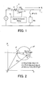
- FIG. 1 shows a digital distance relay 10 set in a power supply system.
- the digital distance relay 10 receives total current "I + IL” of load current IL and fault current "I” from a transmission line 1 via a current transformer 2, and voltage V transformed to an appropriate level via a voltage transformer 3.
- the voltage V consists of a voltage drop component "R + jX” due to the impedance of the transmission line and fault point voltage VF due to fault current I/C (wherein C is a current division ratio of the fault current) through the fault point resistance RA at the fault point F, as shown in Equation (1) below:
- V R ⁇ (I + IL) + jX ⁇ (I + IL) + VF
- VF RA .
- I / C, and "j" is an imaginary unit of complex numbers.
- the fault point voltage VF is a cause of error in impedance measurement of distance relays.
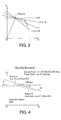
- FB corresponds to RA / C in Equation (2)
- FA corresponds to the fault impedance seen from the relay corresponding to the underlined part of Equation (2).
- the ratio of the magnitudes of FA and AB is
- the phase difference ⁇ between FA and FB shows advanced phase of the load current relative to the fault current I.
- the resistance component rf and the reactance component xf of the measurement error of the impedance seen from the relay are calculated as follows:
- Equation (1) is multiplied by (I + IL)*, which is a conjugate complex number of the current (I + IL) which is applied when the impedance is measured with the relay, and then the real and imaginary parts of both side are respectively equalized as shown in Equations (3) and (4) as follows:
- V ⁇ (I + IL)*] R ⁇
- Re[Zry] R + Re[VF ⁇ (I + IL)*] /
- Im[V ⁇ (I + IL)*] X ⁇
- 2 + Im[VF ⁇ (I + IL)*] Im[Zry] X + Im[VF ⁇ (I + IL)*] /
- Equations (3) and (4) are the impedance measurement error "rf + jxf".
- Equations (3) and (4) show that, when the fault point voltage VF is delayed relative to the current "I + IL" which is used for impedance measurement of the relay, xf becomes negative, and the reactance Xry measured by the relay becomes smaller than the actual reactance X up to the fault point, which is an "over-reach” state.
- xf when the fault point voltage VF is advanced relative to the current "I + IL", xf becomes positive, and the reactance measured by the relay becomes larger than the actual line reactance, which is an "under-reach" state.
- the measurement error of the digital distance relay for measuring the impedance up to the fault point changes much depending the direction and magnitude of the load current, in case of a fault with a load current and with a fault resistance.
- the digital distance relay is set considering maximum measurement error calculated based on the condition of the power supply system and the estimated magnitude of the fault point resistance.
- the performance of the distance relay is adjusted on real-time basis with the change of phase difference.
- a digital distance relay for deciding whether a fault point is within a stipulated operation region by obtaining an impedance up to the fault point through a line equation of a transmission line including terms of resistances and reactances using data of voltage and current of AC power supply system periodically sampled, the relay comprising: a first means for calculating positive-phase resistance Rcal and positive-phase reactance Xcal: a second means for storing load current a stipulated time period prior to the fault was detected: a third means for detecting current in same phase as fault current flowing through the fault point: a fourth means for detecting relative phase of the current detected by the third means relative to current for directly calculating the positive-phase resistance Rcal and the positive-phase reactance Xcal: a fifth means for deciding whether the impedance is within a specified region by applying a value proportional to the relative phase detected by the fourth means: and a sixth means for deciding the fault point is within the stipulated operation region if: (a) when the load
- the relay when an impedance of the transmission line from the relay point up to the fault point is measured and it is decided whether the fault point is within the stipulated operation range, even if the load current is flowing and the fault point has a fault point resistance and there is an impedance measuring error, the relay operates correctly by compensating the relay characteristics.
- a digital distance relay of the first aspect of the present comprising: means for detecting current during the fault which is subtracted by the load current stored in the second means, when the fault is a phase fault: and means for detecting zero-phase current, when the fault is a ground fault.
- the current in substantially the same phase as the fault current flowing through the fault point is detected.
- the input current in the relay partly canceled by the load current is applied when there is a phase fault, and a zero-phase current is applied as a current corresponding to a fault current when there is a ground fault.
- a digital distance relay of the second aspect of the present invention comprising means for detecting electric values of "(IVpc) /
- the fault current is stored in two components, one in a same phase (i.e. inner product) and the other in a perpendicular phase (i.e. outer product) as the positive-phase voltage which does not change much through the occurrence of the fault, and in respect also of the current which is added by the load current during the fault, two components, one in a same phase and the other in a perpendicular phase as the positive-phase voltage are calculated. Then, the stored load current component prior to the fault is canceled from each component of the current during the fault, and the fault point current is detected in the same phase and in the perpendicular phase as the positive-phase voltage.
- and Ips ⁇ (Ipc) /
- tan ⁇ is calculated where ⁇ is a phase angle between FA and FB shown in Figure 2, through calculation of the inner and outer products of the current corresponding to the fault point current and the relay current by canceling the load current prior to the fault from the relay current for measuring impedance during the fault by the following equations:
- a digital distance relay of the first aspect of the present invention comprising: means for detecting relative phase of the current during the fault, in a case of a phase fault, relative to the current detected by the third means, based on a ratio of outer and inner products of a current "I” for directly calculating the resistance and the reactance, and a difference current " ⁇ I” between "I” and a current which is a stipulated period prior to the current "I” and which is in a same phase as the current "I”.
- ⁇ cos( ⁇ ) (I0 ⁇ Ix)s
- ⁇ sin( ⁇ ) tan ( ⁇ ) (I0 ⁇ Ir)s / (I0 ⁇ Ix)c
- a digital distance relay of the first aspect of the invention comprising: means for deciding, in case of a phase fault, that the relay should operate only if "k ⁇ Ips / Ipc" is larger than or equal to "(Xcal - Xs) / (Rcal - Rs)" , wherein Ips and Ipc are calculated by the fourth means, k is a pre-determined constant, Rcal is a resistance component calculated by the first means, Rs is a pre-determined resistance component, Xcal is a reactance component calculated by the first means, and Xs is a predetermined reactance component.
- the relay is decided to operate when the following equation is satisfied, wherein the resistance component Rs and the reactance component Xs are pre-determined, and the electric values of Ips and Ipc are stipulated above: Xcal - Xs ⁇ (Ips / Ipc) ⁇ k ⁇ (Rcal - Rs) where k is a pre-determined constant.
- FA corresponds to the measured value of ⁇
- the line of "k > 1" corresponds to a tendency of "under-reach” compared to the measured value
- the line of "k ⁇ 1" corresponds to a tendency of "over-reach” compared to the measured value.
- the impedance measurement error of the distance relay is compensated on real-time basis by calculating the current phase angle correlation based on the current corresponding to the fault point current and the current for the impedance measuring.
- a digital distance relay of the first aspect of the invention comprising: means for deciding, in a case of a ground fault, that the relay should operate only if (k (I0 ⁇ Ir)s / (I0 ⁇ Ix)c) is larger than or equal to (Xcal - Xs) / (Rcal - Rs), wherein (I0 ⁇ Ir)s and (I0 ⁇ Ix)c) are calculated by the fourth means, k is pre-determined constant, Rcal is a resistance component calculated by the first means, Rs is a pre-determined resistance component, Xcal is a reactance component calculated by the first means, and Xs is a pre-determined reactance component.
- the relay is decided to operate when the following equation is satisfied, wherein the resistance component Rs and the reactance component Xs are pre-determined, and the electric values of (I0 ⁇ Ix)c and (I0 ⁇ Ir)s are stipulated above: Xcal - Xs ⁇ ⁇ (I0 ⁇ Ir)s / (I0 ⁇ Ix)c ⁇ ⁇ k ⁇ (Rcal - Rs) where k is a pre-determined constant.
- the impedance measurement error of the distance relay is compensated on real-time basis by calculating the current phase angle correlation based on the current corresponding to the fault point current and the current for the impedance measuring.
- a digital distance relay of the seventh or eighth aspects of the invention comprising: means for deciding: when the load current stored by the second means is flowing in sending direction, that the relay should operate, if (Xcal - Xs) / (Rcal - Rs) is smaller than a pre-determined constant, and if the fifth means decides that the relay should operate: and when the load current stored by the second means is flowing in receiving direction, that the relay should operate, if (Xcal - Xs) / (Rcal - Rs) is smaller than a pre-determined constant, or if the fifth means decides that the relay should operate: wherein Rcal is a resistance component calculated by the first means, Rs is a pre-determined resistance component, Xcal is a reactance component calculated by the first means, and Xs is a pre-determined reactance component.
- the operation characteristics is changed depending on the direction of the load current prior to the fault.
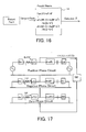
- the sixth means decides that: the region below the straight line NF and below the straight line FM shown in Figure 4 is the relay operation region when the load current stored by the second means is in sending direction: while the region below the straight line NF or below the straight line FL shown in Figure 5 is the relay operation region when the load current stored by the second means is in sending direction.
- a digital distance relay of the seventh or eighth aspects of the invention comprising: means for deciding: when Rcal is smaller than or equal to Rs, that the relay should operate, if (Xcal - Xs) / (Rcal - Rs) is smaller than a pre-determined constant, and if the fifth means decides that the relay should operate: wherein Rcal is a resistance component calculated by the first means, Rs is a pre-determined resistance component, Xcal is a reactance component calculated by the first means, and Xs is a pre-determined reactance component.
- FIG. 6 shows an embodiment of a hardware structure of a digital distance relay for power transmission system according to the present invention.
- the digital distance relay 10 is connected to a power transmission line with a current transformer 2 and a voltage transformer 3.
- the relay 10 comprises an input transducer 4, a sampling-holding circuit 5, an analogue-digital converter 6, a memory 7, a central processing unit (CPU) 8 and an input-output interface circuit 9.
- the input transducer 4 receives the outputs of the current transformer 2 and the voltage transformer 3 and change them into respective appropriate levels.
- the sampling-holding circuit 5 samples and holds the outputs of current and the voltage.
- the analogue-digital converter 6 converts analogue data of the current and voltage output from the sampling-holding circuit 5.
- the memory 7 stores data prior to and during the faults.
- the CPU 8 decides whether the digital distance relay 10 operates and sends a command to turn off the circuit breaker based on the current and the voltage data.
- the input-output interface circuit 9 outputs the decision of the digital distance relay 10.
- Figure 7 shows a logic diagram of the decisions performed by the CPU 8 of the digital distance relay 10 shown in Figure 6.
- the reactance component Xcal and the resistance component Rcal up to the fault point are calculated by line equations of the transmission lines.
- the calculation algorithm is described in IEEE Transaction of Power Delivery, Vol.4, No.4, October 1989, p2025-2031.
- the current (or load current) prior to the fault is stored.
- the magnitude and the phase of the load current may be stored in outer and inner products of the load current of the present phase and the positive-phase voltage of the present phase standard divided by the magnitude of the voltage of the positive-phase as follows:
- the third means 13 detects the current corresponding to the fault point, and it detects the current corresponding to the fault current I / C shown in Figure 1.
- the phase relation between the current corresponding to the fault point current detected by the third means 13 and the current for measuring the impedance of the digital distance relay 10 is detected.
- Figure 9 shows the relation of each load current IL and the current Iry shown as OA for measuring impedance of the digital distance relay, and the current "IF" corresponding to the fault point current, shown as "OF”. From Iry and IF in Figure 9, the phase between them can be detected.
- the fifth means 15 is a means for materializing performance characteristics of the digital distance relay with an operation limit of a line with an inclination proportional to the phase ⁇ relative to the Rs and the Xs which are pre-determined for the relay.
- the sixth means it is decided whether the load current is in a sending direction or in a receiving direction based on the inner product calculated by the second means 12.
- the operation region When the load current is in a sending direction, the operation region is set as a common region (or an "AND" region) of the region with a boundary of a straight line which has a pre-determined inclination and which intersects pre-determined point of (Rs, Xs) and the operation region decided by the fifth means 15.
- the operation region When the load current is in a receiving direction, the operation region is set as an "OR" region of the region with a boundary of a straight line which has a pre-determined inclination and which intersects pre-determined point of (Rs, Xs) and the operation region decided by the fifth means 15.
- Figure 10 shows an example of the third means 13 corresponding to the second aspect of the present invention by which the current corresponding to the fault point current is calculated.
- the current stored prior to the fault is canceled from the current applied for impedance measurement of the digital distance relay, and for a ground fault, the zero-phase current is detected.
- IFs ⁇ (IVps) /
- the reason for setting the positive-phase voltage as the basis is that the positive-phase voltage does not change much prior to and during the fault as shown in Japanese Patent Application Publication (Tokkaihei) 8-19169.
- Figure 12 shows an example of the fourth means 14 corresponding to the fourth aspect of the present invention.
- This figure shows means for detecting phase relation between the current corresponding to the fault current and the current for measuring the impedance of the digital distance relay.
- the same-phase component IFc and the perpendicular-phase component IFs of the current corresponding to the fault point current relative to the positive-phase voltage are as follows: where ⁇ F is an advance phase of IF relative to the positive-phase voltage Vp.
- the same-phase component Iryc and the perpendicular-phase component Irys in respect of the positive-phase voltage of the current for measuring the impedance of the digital distance relay are as follows: where ⁇ ry is an advance phase of Iry relative to the positive-phase voltage Vp.
- Figure 14 shows an example of the fourth means 14 corresponding to the fifth aspect of the present invention. This figure shows means for detecting phase relation between the current "I” for measuring the impedance of the digital distance relay and the differential current " ⁇ I” between the current "I” and the current “IL” in the same phase a time period prior to the current "I".
- Figures 15A and 15B show the relation between the current "I” and the instantaneous value of the current IL a time period prior to the current "I".
- Figure 15B shows the current of the current "i” subtracted by the load current "iL” prior to the fault, i.e. the current corresponding to the fault point current.
- Figure 16 shows an example of the fourth means 14 corresponding to the sixth aspect of the present invention. This figure shows that the fourth means 14 detects phase relation of the zero-phase compensated current "Ir" of the resistance component and the zero-phase compensated current "Ix" of the reactance component as the current for measuring impedance of the digital distance relay, and the zero-phase current corresponding to the fault point current.
- V R ⁇ Ir + jX ⁇ Ix + RF ⁇ IF
- IF the fault current which flows to the fault point
- the symmetric current components in the positive-phase, negative-phase, zero-phase are equal as shown in Figure 17.
- the load current is added.
- the zero-phase circuit is not affected by the load current, and the impedance angles of the both terminals seen from the fault point in the zero-phase circuit are substantially equal.
- the phases of the zero-phase current flowing through the fault point and the zero-phase current inputted to the digital distance relay are substantially equal.
- the zero-phase current I0 which is inputted to the digital distance relay is applied as the current corresponding to the fault point current "IF".
- phase angle of the impedance viewing the fault point resistance is defined by the following equations, which is shown on an R-X plane in Figure 18: since wherein "C0" is the flow division ratio flowing to the relay terminal of the zero-phase current and it is assumed to be a substantially real number.
- Figure 19 shows an example of the fifth means 15 corresponding to the seventh aspect of the present invention.
- This figure shows how the required performance is obtained by adjusting the performance with the resistance component Rcal and reactance component Xcal which are calculated by the first means 11, and a pre-determined constants Rs and Xs.
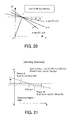
- Figure 20 shows an example of the fifth means 15 corresponding to the eighth aspect of the present invention. This figure shows how the required performance is obtained by applying the electric values of (I0 ⁇ Ir)s and (I0 ⁇ Ix)c of Equation (11) and adjusting the resistance component Rcal and the reactance component Xcal which are directly calculated by the digital distance relay, and pre-determined constants Rs and Xs.
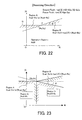
- Figures 21 and 22 show an example of the sixth means 16 corresponding to the ninth aspect of the present invention.
- Figure 21 shows how the required performance is obtained if the load current prior to the fault was in a sending direction.
- Figure 22 shows how the required performance is obtained if the load current prior to the fault was in a receiving direction.
- Figure 23 shows an example of the sixth means 16 corresponding to the tenth aspect of the present invention. This figure shows that the required performance is obtained by taking the region C when the resistance component Rcal calculated by the first means is smaller than the pre-determined value Rs, and that the required performance is obtained by taking the region D when the resistance component Rcal calculated by the first means is larger than the pre-determined value Rs.
- the region C is stipulated by the following formula: Xcal - Xs ⁇ ⁇ ⁇ (Rcal - Rs)
- the region D is stipulated by Equations (25) or (26) as follows: Xcal - Xs ⁇ k ⁇ tan( ⁇ ) ⁇ (Rcal - Rs)
Landscapes
- Physics & Mathematics (AREA)
- General Physics & Mathematics (AREA)
- Emergency Protection Circuit Devices (AREA)
- Locating Faults (AREA)
Abstract
Description
- This invention is related to a digital distance relay for measuring impedance up to the point of the fault with a fault point resistance in an AC power supply system with load current.
- Impedance of the distance relay in the prior art is set by estimating impedance measurement errors arising from fault with resistance of fault point in a power supply system with load current. At a sending terminal, tendency of so called "over-reach" is seen where reactance component of the impedance is seen smaller than actual value. At a receiving terminal, tendency of so called "under-reach" is seen where reactance component of the impedance is seen larger than actual value.
- However, terminals where a distance relay is set are not fixed to the sending side or the receiving side, and impedance is usually set considering maximum of the error that can be generated under estimated system conditions.
- Figure 1 shows a
digital distance relay 10 set in a power supply system. As shown in Figure 1, thedigital distance relay 10 receives total current "I + IL" of load current IL and fault current "I" from atransmission line 1 via acurrent transformer 2, and voltage V transformed to an appropriate level via avoltage transformer 3. The voltage V consists of a voltage drop component "R + jX" due to the impedance of the transmission line and fault point voltage VF due to fault current I/C (wherein C is a current division ratio of the fault current) through the fault point resistance RA at the fault point F, as shown in Equation (1) below:
- Equation (1) can be transformed to Equation (2) shown below:


- In Figure 2, FB corresponds to RA / C in Equation (2), and FA corresponds to the fault impedance seen from the relay corresponding to the underlined part of Equation (2).
- The ratio of the magnitudes of FA and AB is |IL / I|, and the phase difference δ between FA and FB shows advanced phase of the load current relative to the fault current I. When the magnitude |IL / I| is changed with a constant phase difference δ, the trace of the impedance Zry seen from the relay becomes a circle as shown in Figure 2. This circle is a trace of the point A where the circumference angle ∠FAB viewing a chord FB (= RA / C) is a constant of ∠FAB = π - δ.
- The resistance component rf and the reactance component xf of the measurement error of the impedance seen from the relay are calculated as follows:
- Equation (1) is multiplied by (I + IL)*, which is a conjugate complex number of the current (I + IL) which is applied when the impedance is measured with the relay, and then the real and imaginary parts of both side are respectively equalized as shown in Equations (3) and (4) as follows:


- The underlined parts of Equations (3) and (4) are the impedance measurement error "rf + jxf".
- Mathematically in general, Vectors A and B have the following relations:


- From the explanation above, it is understood that the measurement error of the digital distance relay for measuring the impedance up to the fault point changes much depending the direction and magnitude of the load current, in case of a fault with a load current and with a fault resistance. However, in the prior art, the digital distance relay is set considering maximum measurement error calculated based on the condition of the power supply system and the estimated magnitude of the fault point resistance.
- Accordingly, it is an objective of the present invention to provide a digital distance relay preventing over-reach and under-reach by detecting phase difference between the current for measuring the impedance of the digital distance relay and the current which is in a substantially same phase as the fault point current. The performance of the distance relay is adjusted on real-time basis with the change of phase difference.
- According to a first aspect of the present invention, there is provided a digital distance relay for deciding whether a fault point is within a stipulated operation region by obtaining an impedance up to the fault point through a line equation of a transmission line including terms of resistances and reactances using data of voltage and current of AC power supply system periodically sampled, the relay comprising: a first means for calculating positive-phase resistance Rcal and positive-phase reactance Xcal: a second means for storing load current a stipulated time period prior to the fault was detected: a third means for detecting current in same phase as fault current flowing through the fault point: a fourth means for detecting relative phase of the current detected by the third means relative to current for directly calculating the positive-phase resistance Rcal and the positive-phase reactance Xcal: a fifth means for deciding whether the impedance is within a specified region by applying a value proportional to the relative phase detected by the fourth means: and a sixth means for deciding the fault point is within the stipulated operation region if: (a) when the load current stored by the second means indicates a sending current direction, the positive-phase resistance Rcal and positive-phase reactance Xcal are within a stipulated region based on a stipulated positive-phase resistance and a stipulated positive-phase reactance, and the impedance is decided within the specified region by the fifth means; or (b) when the load current stored by the second means indicates a receiving current direction, the positive-phase resistance Rcal and positive-phase reactance Xcal are within a stipulated region based on a stipulated positive-phase resistance and a stipulated positive-phase reactance, or the impedance is decided within the specified region by the fifth means.
- By the first aspect of the present invention, when an impedance of the transmission line from the relay point up to the fault point is measured and it is decided whether the fault point is within the stipulated operation range, even if the load current is flowing and the fault point has a fault point resistance and there is an impedance measuring error, the relay operates correctly by compensating the relay characteristics.
- According to a second aspect of the present invention, there is provided a digital distance relay of the first aspect of the present, the third means comprising: means for detecting current during the fault which is subtracted by the load current stored in the second means, when the fault is a phase fault: and means for detecting zero-phase current, when the fault is a ground fault.
- By the second aspect of the present invention, the current in substantially the same phase as the fault current flowing through the fault point is detected. The input current in the relay partly canceled by the load current is applied when there is a phase fault, and a zero-phase current is applied as a current corresponding to a fault current when there is a ground fault.
- According to a third aspect of the present invention, there is provided a digital distance relay of the second aspect of the present invention, the third means comprising means for detecting electric values of "(IVpc) / |Vp| - (ILVpc)M / |VpM|" and "(IVps) / |Vp| - (ILVps)M / |VpM|" when the fault is a phase fault, where IVpc and IVps are, respectively, inner and outer products of the load current during the fault and a stipulated standard electric value, |Vp| is a magnitude of the stipulated standard electric value, (ILVpc)M and (ILVps)M are, respectively, inner and outer products of the load current stored in the second means and a stipulated standard electric value at a same time M, and |VpM| is a magnitude of the standard electric value at the same time M.
- By the third aspect of the present invention, in case of a phase fault, the fault current is stored in two components, one in a same phase (i.e. inner product) and the other in a perpendicular phase (i.e. outer product) as the positive-phase voltage which does not change much through the occurrence of the fault, and in respect also of the current which is added by the load current during the fault, two components, one in a same phase and the other in a perpendicular phase as the positive-phase voltage are calculated. Then, the stored load current component prior to the fault is canceled from each component of the current during the fault, and the fault point current is detected in the same phase and in the perpendicular phase as the positive-phase voltage.
- According to a fourth aspect of the present invention, there is provided a digital distance relay of the third aspect of the invention, the fourth means comprising: means for calculating, in case of a phase fault,


- By the fourth aspect of the present invention, when a phase fault is detected, tanθ is calculated where θ is a phase angle between FA and FB shown in Figure 2, through calculation of the inner and outer products of the current corresponding to the fault point current and the relay current by canceling the load current prior to the fault from the relay current for measuring impedance during the fault by the following equations:
- The inner product of a current corresponding to the fault current and the current used when the impedance of the relay is measured (added by the load current):


- The outer product of a current corresponding to the fault current and the current used when the impedance of the relay is measured (added by the load current):


- From those equations, advance or delay of the phase of the current during the fault to the current corresponding to the fault current flowing through the fault point.
- According to a fifth aspect of the present invention, there is provided a digital distance relay of the first aspect of the present invention, the fourth means comprising: means for detecting relative phase of the current during the fault, in a case of a phase fault, relative to the current detected by the third means, based on a ratio of outer and inner products of a current "I" for directly calculating the resistance and the reactance, and a difference current "ΔI" between "I" and a current which is a stipulated period prior to the current "I" and which is in a same phase as the current "I".
- By the fifth aspect of the present invention, when a phase fault is detected, the inner and outer products of ΔI and "I" are calculated and "tan θ" is calculated as follows, where "I" is a current for directly calculating resistance and reactance components, ΔI = I - IL (instant value) is a difference between "I" and IL which is the current at a time a stipulated period earlier (corresponding to a load current), and θ is the phase angle between FA and FB shown in Figure 2.

- From the equations above, advance or delay of the phase of the current flowing during the fault to the current corresponding to the fault current flowing through the fault point is detected.
- According to a sixth aspect of the present invention, there is provided a digital distance relay of the first aspect of the present invention, the fourth means comprising: means for detecting phase of current during the fault relative to the current detected by the third means when a ground fault has occurred, from a ratio of an outer product (I0 · Ir)s and an inner product (I0 · Ix)c; where the outer product (I0 · Ir)s is an outer product of a zero-phase current I0 and a current Ir = ia + (kr - 1) · i0, where "ia" is a ground fault phase current, " kr " is a value proportional to a ratio of a zero-phase resistance component and positive-phase resistance component of the transmission line impedance: and the inner product (I0 · Ix)c is an inner product of a zero-phase current I0 and a current "Ix = ia + (kx - 1) · i0" , where "kx" is a value proportional to a ratio of a zero-phase reactance component and positive-phase reactance component of the transmission line impedance.
- By the sixth aspect of the present invention, when a ground fault is detected, a current Ir = ia + (kr - 1) · i0 is applied to a current for calculating resistance and reactance components to calculate the outer product (I0 · Ir)s and the inner product (I0 · Ix)c. Then, tan(θ) is calculated as follows, where θ is a phase angle between FA and FA shown in Figure 2:

- From the equations above, advance or delay of the phase of the current Ir and Ix for measuring resistance and reactance components up to the fault point during the fault to the zero-phase current "i0" corresponding to the fault current flowing the fault point is detected.
- According to a seventh aspect of the present invention, there is provided a digital distance relay of the first aspect of the invention, the fifth means comprising: means for deciding, in case of a phase fault, that the relay should operate only if "k · Ips / Ipc" is larger than or equal to "(Xcal - Xs) / (Rcal - Rs)" , wherein Ips and Ipc are calculated by the fourth means, k is a pre-determined constant, Rcal is a resistance component calculated by the first means, Rs is a pre-determined resistance component, Xcal is a reactance component calculated by the first means, and Xs is a predetermined reactance component.
- By the seventh aspect of the present invention, when a phase fault is detected, the resistance component Rcal and the reactance component Xcal up to the fault point are separately calculated from the electric values between the short-circuited phases. Then, the relay is decided to operate when the following equation is satisfied, wherein the resistance component Rs and the reactance component Xs are pre-determined, and the electric values of Ips and Ipc are stipulated above:

- The above equation is transformed as follows:

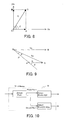
- Where the constant k is put k = 1.0 + ε, and ε is set positive when it is set larger than the calculated θ shown in Figure 3, and is set negative when it is set smaller, as shown in Figure 3.
- In Figure 3, FA corresponds to the measured value of θ, and the line of "k > 1" corresponds to a tendency of "under-reach" compared to the measured value, and the line of "k < 1" corresponds to a tendency of "over-reach" compared to the measured value.
- Thus, the impedance measurement error of the distance relay is compensated on real-time basis by calculating the current phase angle correlation based on the current corresponding to the fault point current and the current for the impedance measuring.
- According to an eighth aspect of the present invention, there is provided a digital distance relay of the first aspect of the invention, the fifth means comprising: means for deciding, in a case of a ground fault, that the relay should operate only if (k (I0 · Ir)s / (I0 · Ix)c) is larger than or equal to (Xcal - Xs) / (Rcal - Rs), wherein (I0 · Ir)s and (I0 · Ix)c) are calculated by the fourth means, k is pre-determined constant, Rcal is a resistance component calculated by the first means, Rs is a pre-determined resistance component, Xcal is a reactance component calculated by the first means, and Xs is a pre-determined reactance component.
- By the eighth aspect of the present invention, when a ground fault is detected, the resistance component Rcal and the reactance component Xcal up to the fault point are separately calculated from the electric current compensated for zero-phase. Then, the relay is decided to operate when the following equation is satisfied, wherein the resistance component Rs and the reactance component Xs are pre-determined, and the electric values of (I0 · Ix)c and (I0 · Ir)s are stipulated above:

- The above equation is transformed as follows:

- Thus, the impedance measurement error of the distance relay is compensated on real-time basis by calculating the current phase angle correlation based on the current corresponding to the fault point current and the current for the impedance measuring.
- According to a ninth aspect of the present invention, there is provided a digital distance relay of the seventh or eighth aspects of the invention, the sixth means comprising: means for deciding: when the load current stored by the second means is flowing in sending direction, that the relay should operate, if (Xcal - Xs) / (Rcal - Rs) is smaller than a pre-determined constant, and if the fifth means decides that the relay should operate: and when the load current stored by the second means is flowing in receiving direction, that the relay should operate, if (Xcal - Xs) / (Rcal - Rs) is smaller than a pre-determined constant, or if the fifth means decides that the relay should operate: wherein Rcal is a resistance component calculated by the first means, Rs is a pre-determined resistance component, Xcal is a reactance component calculated by the first means, and Xs is a pre-determined reactance component.
- By the ninth aspect of the present invention, the operation characteristics is changed depending on the direction of the load current prior to the fault. Thus, the sixth means decides that: the region below the straight line NF and below the straight line FM shown in Figure 4 is the relay operation region when the load current stored by the second means is in sending direction: while the region below the straight line NF or below the straight line FL shown in Figure 5 is the relay operation region when the load current stored by the second means is in sending direction.
- According to a tenth aspect of the present invention, there is provided a digital distance relay of the seventh or eighth aspects of the invention, the sixth means comprising: means for deciding: when Rcal is smaller than or equal to Rs, that the relay should operate, if (Xcal - Xs) / (Rcal - Rs) is smaller than a pre-determined constant, and if the fifth means decides that the relay should operate: wherein Rcal is a resistance component calculated by the first means, Rs is a pre-determined resistance component, Xcal is a reactance component calculated by the first means, and Xs is a pre-determined reactance component.
- The above and other features and advantages of the present invention will become apparent from the discussion hereinbelow of specific, illustrative embodiments thereof presented in conjunction with the accompanying drawings, in which:
- Figure 1 is a schematic circuit diagram of a power supply system incorporating a distance relay when a fault has occurred;
- Figure 2 is an R-X diagram showing vector relationships in impedance measurements in relation to the present invention;
- Figure 3 is an R-X diagram showing characteristics in relation to the present invention;
- Figure 4 is an R-X diagram showing characteristics in relation to the present invention when the current is in sending direction:
- Figure 5 is an R-X diagram showing characteristics in relation to the present invention when the current is in receiving direction;
- Figure 6 is a schematic block diagram of an embodiment of a distance relay according to the present invention;
- Figure 7 is a logic diagram of an embodiment of a distance relay according to the present invention;
- Figure 8 is a vector diagram showing the function of the second means shown in Figure 7;
- Figure 9 is a vector diagram showing the function of the third means shown in Figure 7;
- Figure 10 is a block diagram of the third means shown in Figure 7;
- Figure 11 is a block diagram of the third means shown in Figure 7 when a phase fault has occurred;
- Figure 12 is a block diagram of the fourth means shown in Figure 7 when a phase fault has occurred;
- Figure 13 is a vector diagram showing the phase relation of the fourth means shown in Figure 7;
- Figure 14 is a block diagram of the fourth means shown in Figure 7 when a phase fault has occurred;
- Figures 15A and 15B are time charts showing effects of the fourth means shown in Figure 7;
- Figure 16 is a block diagram of the fourth means shown in Figure 7;
- Figure 17 is an equivalent circuit for symmetry in case of a one-line ground fault;
- Figure 18 is an R-X diagram showing an effect of the present invention;
- Figure 19 is an R-X diagram showing an effect of the present invention;
- Figure 20 is an R-X diagram showing an effect of the present invention;
- Figure 21 is an R-X diagram showing an effect of the present invention when the current is in sending direction;
- Figure 22 is an R-X diagram showing an effect of the present invention when the current is in receiving direction; and
- Figure 23 is an R-X diagram showing an effect of the present invention.
- Figure 6 shows an embodiment of a hardware structure of a digital distance relay for power transmission system according to the present invention. As shown in Figure 6, the
digital distance relay 10 is connected to a power transmission line with acurrent transformer 2 and avoltage transformer 3. Therelay 10 comprises aninput transducer 4, a sampling-holdingcircuit 5, an analogue-digital converter 6, amemory 7, a central processing unit (CPU) 8 and an input-output interface circuit 9. Theinput transducer 4 receives the outputs of thecurrent transformer 2 and thevoltage transformer 3 and change them into respective appropriate levels. The sampling-holdingcircuit 5 samples and holds the outputs of current and the voltage. The analogue-digital converter 6 converts analogue data of the current and voltage output from the sampling-holdingcircuit 5. Thememory 7 stores data prior to and during the faults. TheCPU 8 decides whether thedigital distance relay 10 operates and sends a command to turn off the circuit breaker based on the current and the voltage data. The input-output interface circuit 9 outputs the decision of thedigital distance relay 10. - Figure 7 shows a logic diagram of the decisions performed by the
CPU 8 of thedigital distance relay 10 shown in Figure 6. - In the first means 11, the reactance component Xcal and the resistance component Rcal up to the fault point are calculated by line equations of the transmission lines. The calculation algorithm is described in IEEE Transaction of Power Delivery, Vol.4, No.4, October 1989, p2025-2031.
- In the second means 12, the current (or load current) prior to the fault is stored. The magnitude and the phase of the load current may be stored in outer and inner products of the load current of the present phase and the positive-phase voltage of the present phase standard divided by the magnitude of the voltage of the positive-phase as follows:
- The inner product becomes:

- And the outer product becomes:

- Then, the instantaneous value of the positive-phase voltage Vp in the a-phase basis, for example, is expressed as follows:

- The relation described above is shown in Figure 8. OA corresponding to the load current OC (IL) component in the same phase as the positive voltage is the inner product, and OB corresponding to the load current OC (IL) component perpendicular to the positive voltage is the outer product.
- The third means 13 detects the current corresponding to the fault point, and it detects the current corresponding to the fault current I / C shown in Figure 1.
- In the fourth means 14, the phase relation between the current corresponding to the fault point current detected by the third means 13 and the current for measuring the impedance of the
digital distance relay 10 is detected. Figure 9 shows the relation of each load current IL and the current Iry shown as OA for measuring impedance of the digital distance relay, and the current "IF" corresponding to the fault point current, shown as "OF". From Iry and IF in Figure 9, the phase between them can be detected. - The fifth means 15 is a means for materializing performance characteristics of the digital distance relay with an operation limit of a line with an inclination proportional to the phase θ relative to the Rs and the Xs which are pre-determined for the relay.
- In the sixth means, it is decided whether the load current is in a sending direction or in a receiving direction based on the inner product calculated by the
second means 12. - When the load current is in a sending direction, the operation region is set as a common region (or an "AND" region) of the region with a boundary of a straight line which has a pre-determined inclination and which intersects pre-determined point of (Rs, Xs) and the operation region decided by the
fifth means 15. When the load current is in a receiving direction, the operation region is set as an "OR" region of the region with a boundary of a straight line which has a pre-determined inclination and which intersects pre-determined point of (Rs, Xs) and the operation region decided by thefifth means 15. - Figure 10 shows an example of the third means 13 corresponding to the second aspect of the present invention by which the current corresponding to the fault point current is calculated. In this example, for a phase fault, the current stored prior to the fault is canceled from the current applied for impedance measurement of the digital distance relay, and for a ground fault, the zero-phase current is detected.
- Figure 11 shows, in case of a phase fault, that the components of the current prior to and during the fault in the same phase as and in perpendicular phase to the positive-phase voltage are calculated, and the components in the same phase and the perpendicular phase of the current prior to the fault are canceled from the corresponding components of the current during the fault by the following equations:


- The reason for setting the positive-phase voltage as the basis is that the positive-phase voltage does not change much prior to and during the fault as shown in Japanese Patent Application Publication (Tokkaihei) 8-19169.
- Figure 12 shows an example of the fourth means 14 corresponding to the fourth aspect of the present invention. This figure shows means for detecting phase relation between the current corresponding to the fault current and the current for measuring the impedance of the digital distance relay. In case of a phase fault, the same-phase component IFc and the perpendicular-phase component IFs of the current corresponding to the fault point current relative to the positive-phase voltage are as follows:

- The same-phase component Iryc and the perpendicular-phase component Irys in respect of the positive-phase voltage of the current for measuring the impedance of the digital distance relay are as follows:

- Therefore, the phase difference θ = θF - θry between the current IF corresponding to the fault current and the current Iry for measuring the impedance of the digital distance relay is calculated by Equation (20) as follows:

- The relation of θ = θF - θry, IF and Iry in the Equation (20) is shown in Figure 13.
- Figure 14 shows an example of the fourth means 14 corresponding to the fifth aspect of the present invention. This figure shows means for detecting phase relation between the current "I" for measuring the impedance of the digital distance relay and the differential current "ΔI" between the current "I" and the current "IL" in the same phase a time period prior to the current "I".
- Figures 15A and 15B show the relation between the current "I" and the instantaneous value of the current IL a time period prior to the current "I". In Figure 15A, the instantaneous current "i" for measuring the impedance of the digital distance relay is the sum "i = iF + iL" of the instantaneous value corresponding to the fault current "iF" and the load current "iL". The instantaneous current "i" is the load current "iL", since iF = 0. Figure 15B shows the current of the current "i" subtracted by the load current "iL" prior to the fault, i.e. the current corresponding to the fault point current.
- Figure 16 shows an example of the fourth means 14 corresponding to the sixth aspect of the present invention. This figure shows that the fourth means 14 detects phase relation of the zero-phase compensated current "Ir" of the resistance component and the zero-phase compensated current "Ix" of the reactance component as the current for measuring impedance of the digital distance relay, and the zero-phase current corresponding to the fault point current. The voltage V during the ground fault is expressed with the resistance R and reactance X of the transmission line and the fault point resistance RF as follows:


- In the equations shown above, the zero-phase current I0 which is inputted to the digital distance relay is applied as the current corresponding to the fault point current "IF".
- The phase angle of the impedance viewing the fault point resistance is defined by the following equations, which is shown on an R-X plane in Figure 18:


- When the zero-phase current I0 is applied as the current corresponding to the fault point current IF, the phase θ in the equation above is detected.
- Figure 19 shows an example of the fifth means 15 corresponding to the seventh aspect of the present invention. This figure shows how the required performance is obtained by adjusting the performance with the resistance component Rcal and reactance component Xcal which are calculated by the first means 11, and a pre-determined constants Rs and Xs. The operation decision equation is linear as shown in the following equation:


- Figure 20 shows an example of the fifth means 15 corresponding to the eighth aspect of the present invention. This figure shows how the required performance is obtained by applying the electric values of (I0 · Ir)s and (I0 · Ix)c of Equation (11) and adjusting the resistance component Rcal and the reactance component Xcal which are directly calculated by the digital distance relay, and pre-determined constants Rs and Xs. The operation decision equation becomes linear as follows:


- Figures 21 and 22 show an example of the sixth means 16 corresponding to the ninth aspect of the present invention. Figure 21 shows how the required performance is obtained if the load current prior to the fault was in a sending direction. Figure 22 shows how the required performance is obtained if the load current prior to the fault was in a receiving direction.
- Figure 23 shows an example of the sixth means 16 corresponding to the tenth aspect of the present invention. This figure shows that the required performance is obtained by taking the region C when the resistance component Rcal calculated by the first means is smaller than the pre-determined value Rs, and that the required performance is obtained by taking the region D when the resistance component Rcal calculated by the first means is larger than the pre-determined value Rs. The region C is stipulated by the following formula:


- Some embodiments of the present invention have been disclosed above. Numerous modifications and variations of the present invention are possible in light of the above teachings. It is therefore to be understood that, within the scope of the appended claims, the present invention can be practiced in a manner other than as specifically described herein.
- The entire disclosure of Japanese Patent Application No. 2000-194556 filed on July 28, 2000 including specification, claims drawings and summary are incorporated herein by reference in its entirety.
Claims (12)
- A digital distance relay for deciding whether a fault point is within a stipulated operation region by obtaining an impedance up to the fault point through a line equation of a transmission line including terms of resistances and reactances using data of voltage and current of AC power supply system periodically sampled, the relay comprising:a first means for calculating positive-phase resistance Rcal and positive-phase reactance Xcal;a second means for storing load current a stipulated time period prior to the fault was detected;a third means for detecting current in same phase as fault current flowing through the fault point;a fourth means for detecting relative phase of the current detected by the third means relative to current for directly calculating the positive-phase resistance Rcal and the positive-phase reactance Xcal;a fifth means for deciding whether the impedance is within a specified region by applying a value proportional to the relative phase detected by the fourth means; anda sixth means for deciding the fault point is within the stipulated operation region if: (a) when the load current stored by the second means indicates a sending current direction, the positive-phase resistance Rcal and positive-phase reactance Xcal are within a stipulated region based on a stipulated positive-phase resistance and a stipulated positive-phase reactance, and the impedance is decided within the specified region by the fifth means; or (b) when the load current stored by the second means indicates a receiving current direction, the positive-phase resistance Rcal and positive-phase reactance Xcal are within a stipulated region based on a stipulated positive-phase resistance and a stipulated positive-phase reactance, or the impedance is decided within the specified region by the fifth means.
- A distance relay according to Claim 1, the third means comprising:means for detecting current during the fault which is subtracted by the load current stored in the second means, when the fault is a phase fault: andmeans for detecting zero-phase current, when the fault is a ground fault.
- A distance relay according to Claim 2, the third means comprising means for detecting electric values of "(IVpc) / |Vp| - (ILVpc)M / |VpM|" and "(IVps) / |Vp| - (ILVps)M / |VpM|" when the fault is a phase fault,
where IVpc and IVps are, respectively, inner and outer products of the load current during the fault and a stipulated standard electric value, |Vp| is a magnitude of the stipulated standard electric value, (ILVpc)M and (ILVps)M are, respectively, inner and outer products of the load current stored in the second means and a stipulated standard electric value at a same time M, and |VpM| is a magnitude of the standard electric value at the same time M. - A distance relay according to Claim 3, the fourth means comprising:means for calculating, in case of a phase fault,

 means for detecting relative phase of the current during the fault relative to the current in same phase as the current detected by the third means.
 - A distance relay according to Claim 1, the fourth means comprising:means for detecting relative phase of the current during the fault, in a case of a phase fault, relative to the current detected by the third means, based on a ratio of outer and inner products of a current "I" for directly calculating the resistance and the reactance, and a difference current "ΔI" between "I" and a current which is a stipulated period prior to the current "I" and which is in a same phase as the current "I".
- A distance relay according to Claim 1, the fourth means comprising:means for detecting phase of current during the fault relative to the current detected by the third means when a ground fault has occurred, from a ratio of an outer product (I0 · Ir)s and an inner product (I0 · Ix)c;where the outer product (I0 · Ir)s is an outer product of a zero-phase current I0 and a current Ir = ia + (kr - 1) · i0, where ia is a ground fault phase current, kr is a value proportional to a ratio of a zero-phase resistance component and positive-phase resistance component of the transmission line impedance; andthe inner product (I0 · Ix)c is an inner product of a zero-phase current I0 and a current "Ix = ia + (kx - 1) · i0" , where kx is a value proportional to a ratio of a zero-phase reactance component and positive-phase reactance component of the transmission line impedance.
- A distance relay according to Claim 1, the fifth means comprising:means for deciding, in a case of a phase fault, that the relay should operate only if "k Ips / Ipc" is larger than or equal to "(Xcal - Xs) / (Rcal - Rs)" ,wherein:Ips and Ipc are calculated by the fourth means using the following equations:

 k is a pre-determined constant, Rcal is a resistance component calculated by the first means, Rs is a pre-determined resistance component, Xcal is a reactance component calculated by the first means, and Xs is a pre-determined reactance component.
 - A distance relay according to Claim 1, the fifth means comprising:means for deciding, in a case of a ground fault, that the relay should operate only if (k (I0 · Ir)s / (I0 · Ix)c) is larger than or equal to (Xcal - Xs) / (Rcal - Rs),wherein:(I0 · Ir)s is an outer product of a zero-phase current I0 and a current Ir = ia + (kr - 1) · i0, where ia is a ground fault phase current, kr is a value proportional to a ratio of a zero-phase resistance component and positive-phase resistance component of the transmission line impedance; and(I0 · Ix)c is an inner product of a zero-phase current I0 and a current "Ix = ia + (kx - 1) · i0" , where kx is a value proportional to a ratio of a zero-phase reactance component and positive-phase reactance component of the transmission line impedance; andk is pre-determined constant, Rcal is a resistance component calculated by the first means, Rs is a pre-determined resistance component, Xcal is a reactance component calculated by the first means, and Xs is a pre-determined reactance component.
- A distance relay according to Claim 7, the sixth means comprising:means for deciding:wherein Rcal is a resistance component calculated by the first means, Rs is a pre-determined resistance component, Xcal is a reactance component calculated by the first means, and Xs is a pre-determined reactance component.when the load current stored by the second means is flowing in sending direction, that the relay should operate, if (Xcal - Xs) / (Rcal - Rs) is smaller than a pre-determined constant, and if the fifth means decides that the relay should operate; andwhen the load current stored by the second means is flowing in receiving direction, that the relay should operate, if (Xcal - Xs) / (Rcal - Rs) is smaller than a pre-determined constant, or if the fifth means decides that the relay should operate;
- A distance relay according to Claim 7, the sixth means comprising:means for deciding:wherein Rcal is a resistance component calculated by the first means, Rs is a pre-determined resistance component, Xcal is a reactance component calculated by the first means, and Xs is a pre-determined reactance component.when Rcal is smaller than or equal to Rs, that the relay should operate, if (Xcal - Xs) / (Rcal - Rs) is smaller than a pre-determined constant, and if the fifth means decides that the relay should operate;
- A distance relay according to Claim 8, the sixth means comprising:means for deciding:wherein Rcal is a resistance component calculated by the first means, Rs is a pre-determined resistance component, Xcal is a reactance component calculated by the first means, and Xs is a pre-determined reactance component.when the load current stored by the second means is flowing in sending direction, that the relay should operate, if (Xcal - Xs) / (Rcal - Rs) is smaller than a pre-determined constant, and if the fifth means decides that the relay should operate; andwhen the load current stored by the second means is flowing in receiving direction, that the relay should operate, if (Xcal - Xs) / (Rcal - Rs) is smaller than a pre-determined constant, or if the fifth means decides that the relay should operate;
- A distance relay according to Claim 8, the sixth means comprising:means for deciding:wherein Rcal is a resistance component calculated by the first means, Rs is a pre-determined resistance component, Xcal is a reactance component calculated by the first means, and Xs is a pre-determined reactance component.when Rcal is smaller than or equal to Rs, that the relay should operate, if (Xcal - Xs) / (Rcal - Rs) is smaller than a pre-determined constant, and if the fifth means decides that the relay should operate;
Applications Claiming Priority (2)
| Application Number | Priority Date | Filing Date | Title |
|---|---|---|---|
| JP2000194556A JP3456952B2 (en) | 2000-06-28 | 2000-06-28 | Digital type distance relay |
| JP2000194556 | 2000-06-28 |
Publications (3)
| Publication Number | Publication Date |
|---|---|
| EP1168558A2 true EP1168558A2 (en) | 2002-01-02 |
| EP1168558A3 EP1168558A3 (en) | 2005-06-08 |
| EP1168558B1 EP1168558B1 (en) | 2007-04-25 |
Family
ID=18693362
Family Applications (1)
| Application Number | Title | Priority Date | Filing Date |
|---|---|---|---|
| EP01114839A Expired - Lifetime EP1168558B1 (en) | 2000-06-28 | 2001-06-28 | Digital distance relay |
Country Status (6)
| Country | Link |
|---|---|
| US (1) | US6498709B2 (en) |
| EP (1) | EP1168558B1 (en) |
| JP (1) | JP3456952B2 (en) |
| KR (1) | KR20020001637A (en) |
| CN (1) | CN1330439A (en) |
| DE (1) | DE60128034T2 (en) |
Cited By (1)
| Publication number | Priority date | Publication date | Assignee | Title |
|---|---|---|---|---|
| WO2007090484A1 (en) * | 2006-02-10 | 2007-08-16 | Abb Technology Ltd | Method and adaptive distance protection relay for power transmission lines |
Families Citing this family (12)
| Publication number | Priority date | Publication date | Assignee | Title |
|---|---|---|---|---|
| KR100393909B1 (en) * | 2001-03-29 | 2003-08-06 | 유호전기공업주식회사 | Methol of distance relay for protecting transmission line with removal reactance effect |
| US6671151B2 (en) * | 2001-10-03 | 2003-12-30 | Eaton Corporation | Network protector relay and method of controlling a circuit breaker employing two trip characteristics |
| JP3830824B2 (en) * | 2002-01-28 | 2006-10-11 | 株式会社東芝 | Digital directional relay |
| CN1300906C (en) * | 2002-06-02 | 2007-02-14 | 国电南京自动化股份有限公司 | Quick discrimination method for dynamic impedance of parallel reactor |
| JP4020304B2 (en) * | 2002-08-09 | 2007-12-12 | 株式会社東芝 | Ground fault direction relay and ground fault direction relay device |
| WO2010016555A1 (en) | 2008-08-07 | 2010-02-11 | 三菱化学株式会社 | Polymer, material for luminescent layer, material for organic electroluminescent element, composition for organic electroluminescent element, and organic electroluminescent element, solar cell element, organic el display device, and organic el lighting utilizing same |
| US7944213B2 (en) * | 2009-09-24 | 2011-05-17 | General Electric Company | Ground fault detection device |
| RU2447454C1 (en) * | 2010-11-01 | 2012-04-10 | Александр Леонидович Куликов | Distance protection method for power transmission line |
| DE102011115243A1 (en) * | 2011-09-28 | 2013-03-28 | Airbus Operations Gmbh | Protection element with integrated distance protection with real-time adaptation of the tripping time for the detection and separation of high-impedance faults in meshed networks |
| RU2527491C2 (en) * | 2012-10-24 | 2014-09-10 | Александр Леонидович Куликов | Method of filtering industrial frequency signals |
| CN107910856B (en) * | 2017-12-14 | 2019-07-26 | 南京合智电力科技有限公司 | The analysis method and control method of Sudden Changing Rate distance relay under impedance plane |
| CN110414095B (en) * | 2019-07-11 | 2023-06-27 | 上海交通大学 | Data preprocessing method in fluid-solid load spline interpolation conversion |
Family Cites Families (7)
| Publication number | Priority date | Publication date | Assignee | Title |
|---|---|---|---|---|
| JPS55127829A (en) * | 1979-03-27 | 1980-10-03 | Tokyo Shibaura Electric Co | Digital distance relay unit |
| US4371908A (en) * | 1979-09-17 | 1983-02-01 | Tokyo Shibaura Denki Kabushiki Kaisha | Digital protective relaying systems |
| US4329727A (en) * | 1980-07-16 | 1982-05-11 | General Electric Company | Directional power distance relay |
| JPS5854825A (en) * | 1981-09-29 | 1983-03-31 | 株式会社東芝 | Protective relay unit |
| JPS6240019A (en) * | 1985-08-13 | 1987-02-21 | 三菱電機株式会社 | Digital distance relay system |
| SE459946B (en) * | 1987-12-29 | 1989-08-21 | Asea Ab | RELAY PROTECTION WITH SELECTIVE PHASE SELECTION FOR DOUBLE CABLES |
| JP3790053B2 (en) * | 1998-10-14 | 2006-06-28 | 株式会社東芝 | Distance relay |
-
2000
- 2000-06-28 JP JP2000194556A patent/JP3456952B2/en not_active Expired - Fee Related
-
2001
- 2001-06-27 US US09/891,294 patent/US6498709B2/en not_active Expired - Lifetime
- 2001-06-27 KR KR1020010037156A patent/KR20020001637A/en not_active Ceased
- 2001-06-28 DE DE60128034T patent/DE60128034T2/en not_active Expired - Lifetime
- 2001-06-28 EP EP01114839A patent/EP1168558B1/en not_active Expired - Lifetime
- 2001-06-28 CN CN01115780A patent/CN1330439A/en active Pending
Cited By (2)
| Publication number | Priority date | Publication date | Assignee | Title |
|---|---|---|---|---|
| WO2007090484A1 (en) * | 2006-02-10 | 2007-08-16 | Abb Technology Ltd | Method and adaptive distance protection relay for power transmission lines |
| US7872478B2 (en) | 2006-02-10 | 2011-01-18 | Abb Technology Ltd. | Method and adaptive distance protection relay for power transmission lines |
Also Published As
| Publication number | Publication date |
|---|---|
| EP1168558A3 (en) | 2005-06-08 |
| US20020012213A1 (en) | 2002-01-31 |
| DE60128034D1 (en) | 2007-06-06 |
| US6498709B2 (en) | 2002-12-24 |
| CN1330439A (en) | 2002-01-09 |
| DE60128034T2 (en) | 2008-01-03 |
| JP3456952B2 (en) | 2003-10-14 |
| EP1168558B1 (en) | 2007-04-25 |
| JP2002010478A (en) | 2002-01-11 |
| KR20020001637A (en) | 2002-01-09 |
Similar Documents
| Publication | Publication Date | Title |
|---|---|---|
| US6498709B2 (en) | Digital distance relay | |
| EP1982395B1 (en) | Method and adaptive distance protection relay for power transmission lines | |
| CN1866043B (en) | Systems and methods for determining location of relative ground faults | |
| US9476931B2 (en) | Method for fault location analysis of ungrounded distribution systems | |
| US6584417B1 (en) | Method and directional element for fault direction determination in a capacitance-compensated line | |
| US10656197B2 (en) | Accurate fault location method based on local measurements and remote currents | |
| US20120206149A1 (en) | Method and Apparatus for Ground Distance Protection | |
| US6104182A (en) | Method of deriving a signal indicating an oscillation in an electric power supply system | |
| KR20030069379A (en) | Method for detecting line to ground fault location for power systems | |
| JP5442282B2 (en) | Method and apparatus for estimating generator output | |
| CN116896051A (en) | Methods, devices and systems for adapting distance protection against reactive effects due to remote feed-in and fault resistance | |
| JP3460336B2 (en) | Fault location method for multi-terminal transmission lines | |
| JP4921246B2 (en) | Ground fault distance relay | |
| US11075519B2 (en) | Bidirectional capacitor bank control | |
| JP3630272B2 (en) | Digital ground fault distance relay | |
| JP3191527B2 (en) | One-phase disconnection continuous monitoring method | |
| JP3560297B2 (en) | Ground fault distance relay device | |
| JP6907167B2 (en) | High-voltage insulation monitoring device and high-voltage insulation monitoring method | |
| Voloh et al. | Fault locator based on line current differential relays synchronized measurements | |
| EP4557544A1 (en) | Identifying fault direction for power networks connected with inverter-based renewable resources | |
| EP3141918B1 (en) | Improvements in or relating to determining a fault location in a power transmission medium | |
| JP2000227453A (en) | Spotting of failure position in electric power transmission system | |
| JP2863952B2 (en) | Ground fault fault location method and device, ground fault distance relay | |
| JP2000088910A (en) | Locating apparatus for failure point | |
| JPH063402A (en) | Failure point locator |
Legal Events
| Date | Code | Title | Description |
|---|---|---|---|
| PUAI | Public reference made under article 153(3) epc to a published international application that has entered the european phase |
Free format text: ORIGINAL CODE: 0009012 |
|
| 17P | Request for examination filed |
Effective date: 20010628 |
|
| AK | Designated contracting states |
Kind code of ref document: A2 Designated state(s): AT BE CH CY DE DK ES FI FR GB GR IE IT LI LU MC NL PT SE TR |
|
| AX | Request for extension of the european patent |
Free format text: AL;LT;LV;MK;RO;SI |
|
| PUAL | Search report despatched |
Free format text: ORIGINAL CODE: 0009013 |
|
| AK | Designated contracting states |
Kind code of ref document: A3 Designated state(s): AT BE CH CY DE DK ES FI FR GB GR IE IT LI LU MC NL PT SE TR |
|
| AX | Request for extension of the european patent |
Extension state: AL LT LV MK RO SI |
|
| RIC1 | Information provided on ipc code assigned before grant |
Ipc: 7G 01R 31/08 A Ipc: 7H 02H 3/40 B |
|
| AKX | Designation fees paid |
Designated state(s): DE FR SE |
|
| GRAP | Despatch of communication of intention to grant a patent |
Free format text: ORIGINAL CODE: EPIDOSNIGR1 |
|
| GRAS | Grant fee paid |
Free format text: ORIGINAL CODE: EPIDOSNIGR3 |
|
| GRAA | (expected) grant |
Free format text: ORIGINAL CODE: 0009210 |
|
| AK | Designated contracting states |
Kind code of ref document: B1 Designated state(s): DE FR SE |
|
| REF | Corresponds to: |
Ref document number: 60128034 Country of ref document: DE Date of ref document: 20070606 Kind code of ref document: P |
|
| REG | Reference to a national code |
Ref country code: SE Ref legal event code: TRGR |
|
| ET | Fr: translation filed | ||
| PLBE | No opposition filed within time limit |
Free format text: ORIGINAL CODE: 0009261 |
|
| STAA | Information on the status of an ep patent application or granted ep patent |
Free format text: STATUS: NO OPPOSITION FILED WITHIN TIME LIMIT |
|
| 26N | No opposition filed |
Effective date: 20080128 |
|
| PGFP | Annual fee paid to national office [announced via postgrant information from national office to epo] |
Ref country code: SE Payment date: 20090605 Year of fee payment: 9 |
|
| EUG | Se: european patent has lapsed | ||
| REG | Reference to a national code |
Ref country code: FR Ref legal event code: ST Effective date: 20110228 |
|
| PG25 | Lapsed in a contracting state [announced via postgrant information from national office to epo] |
Ref country code: FR Free format text: LAPSE BECAUSE OF NON-PAYMENT OF DUE FEES Effective date: 20100630 |
|
| PG25 | Lapsed in a contracting state [announced via postgrant information from national office to epo] |
Ref country code: SE Free format text: LAPSE BECAUSE OF NON-PAYMENT OF DUE FEES Effective date: 20100629 |
|
| PGFP | Annual fee paid to national office [announced via postgrant information from national office to epo] |
Ref country code: FR Payment date: 20090611 Year of fee payment: 9 |
|
| PGFP | Annual fee paid to national office [announced via postgrant information from national office to epo] |
Ref country code: DE Payment date: 20140625 Year of fee payment: 14 |
|
| REG | Reference to a national code |
Ref country code: DE Ref legal event code: R119 Ref document number: 60128034 Country of ref document: DE |
|
| PG25 | Lapsed in a contracting state [announced via postgrant information from national office to epo] |
Ref country code: DE Free format text: LAPSE BECAUSE OF NON-PAYMENT OF DUE FEES Effective date: 20160101 |