EP1168333A2 - Calibration system - Google Patents
Calibration system Download PDFInfo
- Publication number
- EP1168333A2 EP1168333A2 EP01305219A EP01305219A EP1168333A2 EP 1168333 A2 EP1168333 A2 EP 1168333A2 EP 01305219 A EP01305219 A EP 01305219A EP 01305219 A EP01305219 A EP 01305219A EP 1168333 A2 EP1168333 A2 EP 1168333A2
- Authority
- EP
- European Patent Office
- Prior art keywords
- data sequence
- timing
- clock
- calibration
- data
- Prior art date
- Legal status (The legal status is an assumption and is not a legal conclusion. Google has not performed a legal analysis and makes no representation as to the accuracy of the status listed.)
- Withdrawn
Links
- 238000000034 method Methods 0.000 claims abstract description 58
- 238000012360 testing method Methods 0.000 claims abstract description 39
- 230000008569 process Effects 0.000 claims abstract description 34
- 230000008859 change Effects 0.000 claims description 5
- 239000003550 marker Substances 0.000 description 17
- 230000003111 delayed effect Effects 0.000 description 4
- 230000003287 optical effect Effects 0.000 description 4
- 238000002310 reflectometry Methods 0.000 description 4
- 238000005516 engineering process Methods 0.000 description 3
- 239000000463 material Substances 0.000 description 2
- 238000005259 measurement Methods 0.000 description 2
- 238000012986 modification Methods 0.000 description 2
- 230000004048 modification Effects 0.000 description 2
- 238000012545 processing Methods 0.000 description 2
- 230000005540 biological transmission Effects 0.000 description 1
- 230000001934 delay Effects 0.000 description 1
- 230000001419 dependent effect Effects 0.000 description 1
- 238000001514 detection method Methods 0.000 description 1
- 230000000694 effects Effects 0.000 description 1
- 230000003760 hair shine Effects 0.000 description 1
- 238000001746 injection moulding Methods 0.000 description 1
- 230000007246 mechanism Effects 0.000 description 1
- 230000010355 oscillation Effects 0.000 description 1
Images


Classifications
-
- G—PHYSICS
- G11—INFORMATION STORAGE
- G11B—INFORMATION STORAGE BASED ON RELATIVE MOVEMENT BETWEEN RECORD CARRIER AND TRANSDUCER
- G11B27/00—Editing; Indexing; Addressing; Timing or synchronising; Monitoring; Measuring tape travel
- G11B27/10—Indexing; Addressing; Timing or synchronising; Measuring tape travel
- G11B27/19—Indexing; Addressing; Timing or synchronising; Measuring tape travel by using information detectable on the record carrier
- G11B27/24—Indexing; Addressing; Timing or synchronising; Measuring tape travel by using information detectable on the record carrier by sensing features on the record carrier other than the transducing track ; sensing signals or marks recorded by another method than the main recording
-
- G—PHYSICS
- G11—INFORMATION STORAGE
- G11B—INFORMATION STORAGE BASED ON RELATIVE MOVEMENT BETWEEN RECORD CARRIER AND TRANSDUCER
- G11B27/00—Editing; Indexing; Addressing; Timing or synchronising; Monitoring; Measuring tape travel
- G11B27/36—Monitoring, i.e. supervising the progress of recording or reproducing
-
- G—PHYSICS
- G11—INFORMATION STORAGE
- G11B—INFORMATION STORAGE BASED ON RELATIVE MOVEMENT BETWEEN RECORD CARRIER AND TRANSDUCER
- G11B20/00—Signal processing not specific to the method of recording or reproducing; Circuits therefor
- G11B20/10—Digital recording or reproducing
- G11B20/18—Error detection or correction; Testing, e.g. of drop-outs
- G11B20/1816—Testing
- G11B20/182—Testing using test patterns
-
- G—PHYSICS
- G11—INFORMATION STORAGE
- G11B—INFORMATION STORAGE BASED ON RELATIVE MOVEMENT BETWEEN RECORD CARRIER AND TRANSDUCER
- G11B2220/00—Record carriers by type
- G11B2220/20—Disc-shaped record carriers
- G11B2220/21—Disc-shaped record carriers characterised in that the disc is of read-only, rewritable, or recordable type
- G11B2220/215—Recordable discs
- G11B2220/216—Rewritable discs
-
- G—PHYSICS
- G11—INFORMATION STORAGE
- G11B—INFORMATION STORAGE BASED ON RELATIVE MOVEMENT BETWEEN RECORD CARRIER AND TRANSDUCER
- G11B2220/00—Record carriers by type
- G11B2220/20—Disc-shaped record carriers
- G11B2220/25—Disc-shaped record carriers characterised in that the disc is based on a specific recording technology
- G11B2220/2537—Optical discs
- G11B2220/2562—DVDs [digital versatile discs]; Digital video discs; MMCDs; HDCDs
-
- G—PHYSICS
- G11—INFORMATION STORAGE
- G11B—INFORMATION STORAGE BASED ON RELATIVE MOVEMENT BETWEEN RECORD CARRIER AND TRANSDUCER
- G11B27/00—Editing; Indexing; Addressing; Timing or synchronising; Monitoring; Measuring tape travel
- G11B27/10—Indexing; Addressing; Timing or synchronising; Measuring tape travel
- G11B27/19—Indexing; Addressing; Timing or synchronising; Measuring tape travel by using information detectable on the record carrier
- G11B27/28—Indexing; Addressing; Timing or synchronising; Measuring tape travel by using information detectable on the record carrier by using information signals recorded by the same method as the main recording
- G11B27/30—Indexing; Addressing; Timing or synchronising; Measuring tape travel by using information detectable on the record carrier by using information signals recorded by the same method as the main recording on the same track as the main recording
- G11B27/3027—Indexing; Addressing; Timing or synchronising; Measuring tape travel by using information detectable on the record carrier by using information signals recorded by the same method as the main recording on the same track as the main recording used signal is digitally coded
Definitions
- Bits may also be recorded by a head, on re-writable media.
- re-writable media it is desirable to be able emulate the DVD-ROM format, and also be able to replace a specified data sequence within a data string, such as second data sequence 112 ; with another data sequence, such as new second data sequence 122 .
- the desired result of this edit is edited data string 130 .
- Edited data string 130 has old second data sequence 112 replaced by new data sequence 122 , while data sequences 111 and 113 are unchanged.
Landscapes
- Optical Recording Or Reproduction (AREA)
- Signal Processing For Digital Recording And Reproducing (AREA)
- Testing, Inspecting, Measuring Of Stereoscopic Televisions And Televisions (AREA)
- Digital Magnetic Recording (AREA)
Abstract
Description
- The present invention relates to a method and system for calibrating the timing of recorded data.
- Many information storage systems include a disk shaped storage medium and a playback (read) and record (write) element. This read-write element (hereinafter "head") is proximal to a disk surface, and can be scanned to select a radial position on the disk. The disk spins rapidly beneath the (effectively stationary) head. This enables rapid reading or writing of information on nearly circular bit tracks that cover most of the disk surface. Some types of storage media, such as DVD and CD disks, can be recorded in advance by injection molding the disk with a permanent bit sequence, so that a read-only (ROM) disk is produced.
- A common DVD-ROM format stores a series of files or data sequences as a continuous data string. Figure 1 illustrates such a
data string 110, which includes afirst data sequence 111 followed without delay by asecond data sequence 112, athird data sequence 113, and others not shown. This format is convenient for reading of prerecorded data sequences (i.e. files). - Bits may also be recorded by a head, on re-writable media. With re-writable media, it is desirable to be able emulate the DVD-ROM format, and also be able to replace a specified data sequence within a data string, such as
second data sequence 112; with another data sequence, such as newsecond data sequence 122. The desired result of this edit is editeddata string 130. Editeddata string 130 has oldsecond data sequence 112 replaced bynew data sequence 122, whiledata sequences - Unfortunately, the DVD-ROM format has no mechanism to accurately time the beginning of the over-write process for an edit. Thus, there is often a timing error, Δt, in the writing of a new
second data sequence 122. The data sequences pass rapidly beneath the head, at a velocity, v, that may be radius dependent and is given by the following equation.

- When the write process for
new data sequence 122 begins too early, it writes over part offirst data sequence 111, as shown indata string 140. Furthermore, part of oldsecond data sequence 112 remains. Similarly, when the write-timing ofnew data sequence 122 is delayed, the beginning ofthird data sequence 113 is erased and the beginning of oldsecond data sequence 112 remains, as shown indata string 150. - Thus, the standard DVD-ROM format has the disadvantage that it does not accurately edit data sequences. The edited data sequence is not completely replaced by the new data sequence, and nearby data sequences can be damaged or erased.
- The present invention seeks to provide improved data calibration.
- According to an aspect of the present invention there is provided a method of calibrating timing of recorded data as specified in
claim 1. - According to another aspect of the present invention, there is provided apparatus for calibrating the timing of a write process as specified in claim 7. The preferred embodiment can provide a re-writable DVD format that emulates the DVD-ROM format such that the existing installed base of DVD players and DVD-ROM readers can read the re-writable DVD disk. The embodiment can accurately synchronize new edited data with the existing data on the disk. This method can accurately position recorded data sequences in order to repeatably write and read information. Advantageously, the method can (1) precisely control the time and distance between the data sequence start positions and well defined locations on the disk, (2) precisely position and accurately calibrate the beginning of the write process with the data sequence start position, (3) consistently calibrate the beginning of the write process, independent of which recording device is used, and/or (4) compatibly operate with prior DVD technology.
- The preferred calibration involves (1) writing a calibration data sequence referenced to a timing clock including positions marked on the disk (such as a wobble clock on a DVD disk), (2) measuring the timing offset or phase offset between the calibration data sequence and the clock, (3) writing a test data sequence using the same or a different recording device, (4) measuring the timing offset or phase offset between the test data sequence and the clock, (5) comparing the timing offsets of the calibration and test data sequences, with respect to the clock, (6) iteratively adjusting the timing of the beginning of the write process, and repeating steps (4) and (5) until the timing offsets are equal to within a defined tolerance, and (7) adjusting the delay of the write head relative to the clock by the amount determined in step 6.
- This process calibrates the timing of bits written on DVD +RW disks by different recording devices so that the start position of edited data sequences is repeatably collocated with previous data sequences to a precision better than +/- 0.06 µm.
- An embodiment of the present invention is described below, by way of example only, with reference to the accompanying drawings, in which:
- Figure 1 illustrates data strings in DVD-ROM format.
- Figure 2 illustrates information storage in DVD+RW format.
- Figure 3 illustrates data strings in DVD+RW format.
- Figure 4 illustrates the operation of a wobble clock on a DVD disk.
- Figure 5 illustrates a process flow for calibrating write timing.
- Figure 6 illustrates timing offsets between a data sequence and a wobble clock.
- Figure 7 illustrates measurement of timing offsets between a data sequence and a wobble clock.
- An accurate method to calibrate the timing of the "write" process in a recording system is disclosed. This method is described with reference to digital video disk (DVD) information storage technology, but is also applicable to calibrating the timing of processes in other storage technologies.
- The detailed description is presented in four sections. Section I presents an embodiment of data and recording formats. Section II presents an embodiment of a method for calibrating the timing offset between the write process used to edit data and that previously used to record data. Section III presents an embodiment of a method for measuring the timing offset between recorded data and a clock. Section IV presents an embodiment of measuring the timing offset between data and the clock.
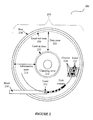
- Figure 2 illustrates information storage on re-writable DVD. A
DVD system 200 includes aDVD disk 210 and a recorder including ahead 250. - The
DVD disk 210 includes aclamping zone 212, aninformation zone 214, and arim region 216. Bits 218 of information are recorded in theinformation zone 214, which consists of a spiral pattern ofalternating land 222 andgroove 224 regions. A bit 218 is defined by a high or low reflectivity where it is written. Bits 218 are recorded in thegroove regions 224, forming spiral tracks containing sequences of bits. A sequence of bits (a data sequence) is shown as a sequence of black and white regions in Figure 2. - The
head 250 includes a servo system that positions thehead 250 radially, at a constant height above a selected track, alaser 252, a light sensor and electric circuitry. - In the read process, the
head laser 252 shines a laser beam on the disk track that passes beneath it. A bit 218 is sensed from the amount of reflected light from the bit that reaches the head sensor. - To record or "write" data, more intense laser light is used to change the local structural properties of the disk material, and hence its reflectivity. Writing a data sequence of bits 218 is achieved by rapidly changing the
laser 252 power as the disk passes beneath, to change the reflectivity of selected regions of adisk groove 224. By this method, data sequences can be recorded in a data format of the invention. - Figure 3 illustrates a data format of the invention.
Data string 310 includesfirst data sequence 111,second data sequence 112,third data sequence 113, anddata address markers Data string 310 can be formed as follows. - When a recording head (e.g. head 250) passes over an
address marker 311, the time of the event is sensed by a "clock channel", as will be described in detail in Section II. The head then begins the process to writefirst data sequence 111. This write process may be delayed (e.g. purposely or by the speed of the head's clock channel electronics), giving a time and position offset 331 between theaddress marker 311 and the start of thefirst data sequence 111. The bits 218 indata sequence 111 are then written exactly as indata string 110 of Figure 1. Likedata string 110,second data sequence 112 ofdata string 310 begins immediately thereafter. The length of the data sequences is such that the position offset 332 between theaddress marker 312 and the start of thefirst data sequence 112 is equal to position offset 331. This relationship is repeated for third and subsequent data sequences, to completedata string 310. - As described above, it is desirable to be able to replace a data sequence, such as
data sequence 112, with another data sequence, such asdata sequence 122. The desired result of this edit isdata string 320. Editeddata string 320 hasdata sequence 112 replaced bydata sequence 122, whiledata sequences second data sequence 122 when thehead 250 passes overaddress marker 312.Address marker 312 is sensed by the clock channel and the head then begins the process to writesecond data sequence 112, with a timing offset 342, as shown indata string 330. As long as the timing offset between address markers and the start of data sequences (e.g. 331, 332 and 342) is maintained at a constant value, this format accurately edits data sequences, so that the edited data sequence is completely replaced by the new data sequence, and nearby data sequences are not damaged or erased. The method and apparatus for calibrating this timing offset between different edits is described in Sections II-IV. - Address markers, such as address markers 311-313 of Figure 3, must be accurately positioned in known locations on the disk, forming a timing reference (clock) that must be collocated with the data on the disk such that a
head 250 can sense their locations during the write process. Figures 4a and 4b illustrate the operation of such a clock,wobble clock 400. Figure 4a shows thedisk surface 410, which includes (1) wobblegrooves 420, (2)land regions 425, (3) average track centers 430, and (4) alaser spot 440. Thewobble grooves 420 andland regions 425 alternate radially, to form the surface of thedisk 410. Eachgroove 420 forms a track upon which data sequences are written. The center 422 of eachgroove 420 oscillates (wobbles) about anaverage track center 430, with an amplitude of about 30 nm and a period of about 4.25 µm. Thewobble grooves 420 also include inverted wobbles 424, that abruptly invert the wobble phase at intervals throughout each data block. The presence or absence of an inverted wobble at specific locations represent bits of data. Together these bits carry information such as the address of a block. One such bit identifies the start of the block address information. Such a bit defined by an inverted wobble may also mark the beginning of data files, such asaddress markers - A laser 455 (see Figure 4b) is positioned by the servo of a
head 450 to maintain alaser spot 440 focussed at theaverage track center 430 of agroove 420 as shown. - Figure 4b shows the wobble
groove detection circuitry 450, which includes (1) ahead 450, (2) alaser 455, (3) a DVD+RW disk 460, (4) an opticalphase selection element 465, (5) alight sensor 470, and (6)sensor circuitry 475.Laser 455 is positioned byhead 450 to focus alaser spot 440 ondisk 460 at theaverage track center 430 of a groove 420 (see Figure 4a). Reflected light, fromgroove 420 and land 425 regions, returns tooptical element 465, where transmission tolight sensor 470 depends on phase.Light sensor 470 separates the light reflected from each side of the average track center 430 (i.e. regions I1 and I2 shown in Figure 4a). Reflected intensities from thegroove regions 420 of I1 and I2 are converted to electrical signals, and sum and difference measurements are output fromcircuit 475 through data channel 480 and clock channel 490. - Data channel 480 includes signal I1 471, signal I2 472, and summing circuit 485. Summing circuit 485 includes
inputs 481 and 482, and output 483. Signal I1 471 connects to input 481. Signal I2 472 connects to input 482. Data channel 480 operates by first receiving signals I1 and I2 fromoptical sensor 470, at summingcircuit inputs 481 and 482; second, summing signals I1 and I2 at summing circuit 485; and third, outputting the signal I1+I2 at output 483. The data channel output is a measure of the reflectivity of the section of thedisk groove 420 beneath thehead laser spot 440 as a function of time. This sum value is not significantly affected by the wobble of thegroove 420. Thus, the data channel senses the time when recorded bits pass beneath the head. In this manner, the data channel determines the timing, and hence position of a data sequence on thedisk 460. Note that the data channel output 483 is delayed from the actual time a bit passes beneath thehead laser spot 440, by the delay of the data channel electronics, so that there is a timing offset between the actual and measured bit positions (described in detail in Section III). - The push-pull tracking channel or clock channel 490 includes signal I1 471, signal I2 472, and differencing circuit 495. Differencing circuit 495 includes inputs 491 and 492, and output 493. Signal I1 471 connects to input 491. Signal I2 472 connects to input 492. Data channel 490 operates by first receiving signals I1 and I2 from
optical sensor 470, at summing circuit inputs 491 and 492; second, subtracting signal I2 from signal I1 at differencing circuit 495; and third, outputting the signal I1-I2 at output 493. The clock channel 490 output is positive when the center of thelaser spot 440 is to the right of the groove center 422, as inPosition A 442; and negative when the laser spot center is to the left of the groove center 422, as in Position B 444 (the sign of these outputs could be reversed, depending on the system layout). Thus, the clock channel produces an oscillating output that directly corresponds to the wobble of the grooves. In this manner, the clock channel determines the timing, and hence position of the wobble grooves on the disk, offset by the delay of the clock channel electronics. Note that an abrupt inversion of the phase of the groove center at an inverted wobble 446 in thewobble groove 420 is directly sensed as an abrupt inversion of the oscillating difference output. - Figure 5 shows a flowchart of a
process 500 to calibrate the write-timing and position of a data sequence written on a DVD disk. - At 510, a re-writable DVD disk is placed in a read-write capable DVD recorder.
- At 520, the recorder checks the formatting to determine whether the disk has been previously formatted and recorded.
- If the disk has not been recorded, at 522 the
head 450 of the recorder formats the disk and writes a calibration data sequence on the disk, using the disk'swobble clock 400 as a time reference. The calibration data sequence is often written in a special calibration zone on the disk (for example, in the lead-in zone 252). This sequence may be a fixed tone at a harmonic to the frequency of the wobble clock reference, or it may be a pseudo random data sequence. The choice depends on the method used to detect the timing offset of the data relative to the wobble clock (discussed in Section IV). - After writing the calibration data sequence, at 550, the recorder may record data at the same data-to-clock timing offset, until it is deemed necessary to perform a timing-offset calibration (perhaps because of a change in ambient temperature or a time elapsed).
- If at 520, the disk had been previously written, then at 530, the head of the recorder reads the calibration data sequence, and measures the timing offset between the beginning of the data sequences (as measured by data channel 482) and the address marker (as measured by clock channel 484). This process is described in detail in Section III.
- At 540, the head writes a test data sequence in a zone near the calibration data sequence, using the
wobble clock 400 as a time reference. At 542, the head of the recorder reads the test data sequence, and measures a second timing offset between thedata channel 482 and theclock channel 484 by the same procedure used for the calibration data sequence. At 544, the measured timing offsets of the calibration and test data sequences are compared. This procedure cancels out the timing offsets of the read process, as will be described in detail in Section III. Thus, the measured difference between the timing offsets of the calibration data sequence and the test data sequence is equal to the actual difference in their timing and hence position with respect to anaddress marker 435 of thewobble clock 400. - At 546, the recorder determines whether the measured write-timing offsets of the test data sequence and the calibration data sequence are the same within a tolerance. If the write-timing offsets are not the same, the timing of the test data sequence write process is advanced or delayed according to the measured difference in the timing offsets. Then, at 540, a new test data sequence is written, and steps 542, 544 and 546 are repeated. If the measured timing offsets between (1) the calibration data sequence and the wobble clock and (2) the test data sequence and the wobble clock are the same within the specified tolerance, then the actual physical location of the start of new data sequences will match that of the old data sequences, within a corresponding tolerance.
- This calibration should be carried out at all potential write speeds.
- Then, at 550, the recorder may record and edit data until it is deemed necessary to perform another calibration.
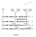
- Figure 6 illustrates a
time line 600 of the position ofhead 450 ondata track 605, and the corresponding output of the digitizeddata channel 610 and theclock channel 615.Data track 605 includes awobble groove 620, aninverted wobble 625, anaddress marker 630, and a "constant tone" oscillatingdata sequence 640, with the same period or "run length" as thewobble groove 620. - The
head 450 passes theaddress marker 630 at a time t0. Theclock channel 615 senses the abrupt inversion of the groove wobble, and outputs a corresponding change in the oscillating signal at time t1, after a processing time delay as shown. Thus, there is a clock channel electronics timing offset t1 -t 0 650 between the actual and measured times that thehead 450 passed theaddress marker 630. - There is a timing offset t2 -
t 0 655 between theaddress marker 630 and the beginning of adata sequence 640 as previously described. - The
head 450 passes the beginning ofdata sequence 640 at a time t2. The data channel 610 senses the beginning of the first bit and begins to output an oscillating signal at t3, after a different processing delay as shown. Thus, there is a data channel timing offset t3 -t 2 660 between the actual and measured times that thehead 450 passed the beginning ofdata sequence 640. - During readback of
data track 605 by the data andclock channels address marker 630 and the beginning of thedata sequence 640 is t3 -t 1 665. This offset 665 between the data and clock channels is a value that can be measured. However, the measured timing offset 665 is equal to the actual write-timing offset 655 plus the difference between thedelays data channel 610 andclock channel 615 respectively. That is, measured offset 655, t3 - t1 = (t2 - t0) + (t3 - t2) - (t1 - t0). The data channel offset (t3 - t2) 660 and clock channel offset (t1 - t0) 650 can vary, and are generally not known during the recording process. Therefore, the actual offset, (t2 - t0) 655, between an address marker and the beginning of a recorded data sequence, is not determined. Thus, reading a written track is insufficient to calibrate the write-timing offset 655 for writing a new data sequence. This calibration error can be particularly large when using a head with different delay times than the head used to write the original data sequences. - However,
calibration process 500 effectively calibrates the write delay for writing to a DVD+RW disk, by any compatible recorder and head. Step 530 of Figure 5 measures (t3 - t1)cal = (t2 - t0)cal + (t3 - t2)recorder - (t1 - t0)recorder of the calibration data sequence. (t3 - t1)cal and (t2 - t0)cal are the measured and actual time offsets respectively, of the calibration data sequence, as measured by an editing recorder. (t3 - t2)recorder and (t1 - t0)recorder are the data and clock channel timing offsets of the recorder. Using the same recorder as inStep 530,Step 542 of Figure 5 measures (t3 - t1)test = (t2 - t0)test + (t3 - t2)recorder - (t1 - t0)recorder of the test data sequence. (t3 - t1)test = (t2 - t0)test are the measured and actual time offsets respectively, of the test data sequence. (t3 - t2)recorder and (t1 - t0)recorder are the data and clock channel timing offsets of the recorder. Step 544 subtracts (t3 - t1)cal from (t3 - t1)test to compare the calibration and test data sequence offsets. The recorder's data and clock channel offsets cancel, as well as the calibration set-point position of the address marker, tl. This leaves a direct measure of the offset between the start of the calibration and test data sequences (t3)test - (t3)cal, with respect to an address marker. When this difference is small, edited data sequences will be accurately positioned to over-write selected old data sequences. - The relationship between position offsets and timing offsets depends upon the velocity of the head. The effect of, for example, channel electronics upon the timing offset may not have the same dependence on the velocity of the head. Therefore, it may be necessary to perform the calibration process over a range of speeds.
- The timing offset between two channels with outputs oscillating at the same frequency (or a harmonic), such as
data channel 610 andclock channel 615, can be determined from their phase offset (Δφ). The timing offset, Δt = Δx/v = B/(v*π)*Δφ, where Δx is the offset in distance, v is the head velocity with respect to the disk, B is the length of a bit, and φ is the phase in radians. The phase determination embodiment of measuring a timing offset is advantageous because it is fast, and employs relatively simple electronics. - Figure 7 illustrates an embodiment of the
phase determination method 700, which employs (1) a datachannel output signal 705, (2) a clockchannel output signal 710, (3) a signal measuring the sign of thedata channel output 715, (4) a signal measuring the sign of theclock channel output 720, and (5) a filteredXOR gate output 725. The sign of thedata channel 715 and the sign of theclock channel 720 are the inputs to the XOR gate that producesoutput 725. -
Phase determination method 700 proceeds as follows. The data channel 480 and clock channel 490 output oscillating signals having a time offset, and hence a phase offset. The oscillating signals (which may have other functional forms, such as a square wave shown in Figure 6) are represented bysinusoidal signals data channel output 705 is converted (e.g. by using a comparator) to asquare wave 715, having a constant positive value when the sign ofsinusoid 705 is any positive value and a constant negative value when the sign ofsinusoid 705 has any negative value. Theclock channel output 710 is similarly converted tosquare wave 720. Square wave signals 715 and 720 are used as inputs to a digital mixer such as an XOR gate. A similar process can employ an analog mixer or a Time Interval Analyzer, TIA. The XOR gate outputs a constant positive value when one but not both ofinputs XOR gate output 725 is a measure of the phase difference between thedata channel 705 and theclock channel 710. For example, when there is no phase offset betweenoutputs XOR gate output 725 is always zero. When the phase offset betweenoutputs XOR gate output 725 is always a constant positive value. When the phase offset betweenoutputs XOR gate output 725 is a constant positive value for part of each cycle as shown in Figure 7. In this manner, the phase delay can be determined as a fraction of pi by, for example, comparing the integrated average output value ofXOR gate 725 to the constant positive output value. A calibration usingcalibration process 500 can be achieved by measuring the output values ofXOR gate 725 upon reading the calibration and test data sequences, and iterating the write-timing until these output values differ by less than a defined tolerance. - When the
data channel outputs 705 result from pseudo-random calibration and test data sequences, the timing offset between two channels, such asdata channel 610 andclock channel 615, can still be determined. One embodiment of measuring the timing offset from pseudo-random data sequences employs direct determination of the timing offset between the sensing of specific bits. The direct determination embodiment requires more sophisticated electronics than the phase determination embodiment, but is advantageous because any recorded data sequence may be used as a calibration data sequence. - A calibration, following
calibration process 500, can be achieved using the direct determination method as follows. A calibration data sequence is read, and the timing offset of one or several zero crossings with respect to an address marker is measured. A copy of the calibration data sequence is then written as a test data sequence, and the timing offset of one or several zero crossings with respect to an address marker is measured. The measured timing offsets of the calibration and test sequences are then compared, and the write-timing is adjusted until the timing offsets differ by less than a defined tolerance. - This method and apparatus to calibrate the write-timing of DVD recorders described above has several advantages over the prior art. It calibrates the timing of the process that writes new data sequences, so that the new data sequences have the same offset relative to reference marks on the disk as old data sequences. This process does not require information about the apparatus used to record the old data. It calibrates the timing of bits written on DVD formats by different recording devices so that the start position of edited data sequences is repeatably collocated with previous data sequences to a precision better than +/- 0.06 µm. This process enables editing of data without erasure of or damage to nearby data files. The DVD disks using this process can be conveniently read by prior art DVD-ROM and other recording devices.
- The foregoing has described new methods and apparatus for calibrating write timing of digital video disks. Modifications thereto will be apparent to those skilled in the art. It is contemplated that changes and modifications may be made to the materials and arrangements of elements without departing from the scope of the invention.
- The disclosure in United States 09/608,600, from which this application claims priority, and in the abstract accompanying this application are incorporated herein by reference.
Claims (9)
- A method (500) of calibrating the timing of recorded data, including the steps of:a) recording a calibration data sequence (522) on a storage medium (200) at a time referenced to a timing clock (400) on the storage medium (200);b) measuring (530) a timing offset (665) between said calibration data sequence (522) and said clock (400);c) writing a test data sequence (540);d) measuring (542) a timing offset (665) between said test data sequence (540) and said clock (400);e) comparing (544) said timing offsets (665) of said calibration data sequence (522) and said test data sequence (540) with respect to said clock (400); andf) correcting the timing (548) of said writing a test data sequence (540) so as to reduce the difference between the timing offsets (665) of said calibration data sequence (522) and said test data sequence (540).
- A method as claimed in claim 1, including:g) iteratively repeating steps c), d), e) and f) until said timing offsets (665) of said calibration data sequence (522) and said test data sequence (540) with respect to said clock (400) are equal to within a defined tolerance (546).
- A method as claimed in claim 1 or 2, wherein said storage medium comprises one of a DVD disk (200), a CD disk, an optically assisted magnetic storage disk, and a magnetic storage disk.
- A method as claimed in claim 1, 2 or 3, wherein said calibration data sequence (522) comprises one of a constant tone data sequence with the same frequency as the clock (640), a constant tone data sequence with a frequency that is a harmonic of the clock frequency, a pseudo-random data sequence and a data sequence containing previously recorded information (111).
- A method as claimed in any preceding claim, wherein said calibrating timing of recorded data (500) is performed for at least two recording speeds.
- A method as claimed in any preceding claim, wherein said calibration data sequence (522) is recorded by a first recording device and said test data sequences (540) are recorded by one of the first recording device and a second recording device.
- Apparatus for calibrating the timing of a write process (500) to a medium 200 including:a clock (400) for providing a series of positions (435) marked on said medium (200); means for providing a calibration data sequence (522);a recording device (450) operable to sense data sequences and said positions marked on said medium (200);a device (475) operable to measure when said recording device (450) senses said data sequences and said positions (435) marked on said medium (200);first time measuring means (530) operable to measure a timing offset (665) between sensing of said calibration data sequence (522) and one of said positions (435) marked on said medium (200);data writing means (540) operable to write a test data sequence with said recording device (450) in response to sensing another of said positions (435) marked on said medium (200);second time measuring means (542) operable to measure a timing offset (665) between sensing of said test data sequence (540) and to sense said another of said positions (435) marked on said medium (200);comparison means (544) operable to compare the timing offsets (665) between sensing of said test data sequence (540) and sensing said another of said positions (435) marked on said medium (200) and the measured timing offset (665) between sensing of said calibration data sequence (522) and one of said positions (435) marked on said medium (200);determining means (546) operable to determine whether the time difference between said compared timing offsets (665) is less than a specified value; andadjusting means (548) operable to change the timing of a write process (540) in response to sensing one of said clock positions (435) on the medium (200), by an amount determined by said time difference determined by said fifth program code (546).
- Apparatus as claimed in claim 7, wherein said writing means is operable to record data on a disk storage medium comprising one of a DVD disk (200), a CD disk, an optically assisted magnetic storage disk and a magnetic storage disk.
- The apparatus as claimed in claim 7 or 8, wherein said calibration data sequence (522) comprises one of a constant tone data sequence with the same frequency as the clock (640), a constant tone data sequence with a frequency that is a harmonic of the clock frequency, a pseudo-random data sequence and a data sequence containing previously recorded information (111).
Applications Claiming Priority (2)
| Application Number | Priority Date | Filing Date | Title |
|---|---|---|---|
| US608600 | 2000-06-30 | ||
| US09/608,600 US6636467B1 (en) | 2000-06-30 | 2000-06-30 | Method and apparatus for accurately calibrating the timing of a write onto storage media |
Publications (2)
| Publication Number | Publication Date |
|---|---|
| EP1168333A2 true EP1168333A2 (en) | 2002-01-02 |
| EP1168333A3 EP1168333A3 (en) | 2003-05-07 |
Family
ID=24437209
Family Applications (1)
| Application Number | Title | Priority Date | Filing Date |
|---|---|---|---|
| EP01305219A Withdrawn EP1168333A3 (en) | 2000-06-30 | 2001-06-15 | Calibration system |
Country Status (5)
| Country | Link |
|---|---|
| US (1) | US6636467B1 (en) |
| EP (1) | EP1168333A3 (en) |
| JP (1) | JP3936152B2 (en) |
| CN (1) | CN1337696A (en) |
| HK (1) | HK1043653A1 (en) |
Cited By (2)
| Publication number | Priority date | Publication date | Assignee | Title |
|---|---|---|---|---|
| EP1291875A3 (en) * | 2001-08-06 | 2004-05-19 | Hewlett-Packard Company | A method and system for write clock synchronization in a data storage system |
| WO2007103454A3 (en) * | 2006-03-07 | 2007-11-22 | Marvell World Trade Ltd | Improved write splice for optical recording channels |
Families Citing this family (10)
| Publication number | Priority date | Publication date | Assignee | Title |
|---|---|---|---|---|
| US7463626B2 (en) * | 2000-11-21 | 2008-12-09 | Roy Subhash C | Phase and frequency drift and jitter compensation in a distributed telecommunications switch |
| JP2002352517A (en) * | 2001-05-28 | 2002-12-06 | Sony Corp | Optical disk device, clock generation method for optical disk device, and light amount setting method for optical disk device |
| CN1324574C (en) * | 2003-07-07 | 2007-07-04 | 联发科技股份有限公司 | A CD burning signal control circuit with alignment function |
| US8023376B2 (en) * | 2004-10-08 | 2011-09-20 | Koninklijke Philips Electronics N.V. | Fast disc recognition by elimination of calibrations |
| US7898932B2 (en) * | 2005-07-19 | 2011-03-01 | Panasonic Corporation | Optical disc recording device and optical disc recording system |
| US8386829B2 (en) * | 2009-06-17 | 2013-02-26 | Macronix International Co., Ltd. | Automatic internal trimming calibration method to compensate process variation |
| CN103257309B (en) * | 2012-02-17 | 2015-10-07 | 安凯(广州)微电子技术有限公司 | Ddr series pcb plate timing compensation method, system and terminal |
| US10936007B2 (en) * | 2019-04-03 | 2021-03-02 | Omnivision Technologies, Inc. | Hybrid method for high-speed serial link skew calibration |
| CN111163311B (en) * | 2020-02-13 | 2022-05-24 | 维沃移动通信有限公司 | Phase calibration method and electronic device |
| CN113541913B (en) * | 2020-11-05 | 2022-08-02 | 中兴通讯股份有限公司 | Clock calibration method, clock calibration device, electronic device, and readable medium |
Family Cites Families (16)
| Publication number | Priority date | Publication date | Assignee | Title |
|---|---|---|---|---|
| US4009490A (en) * | 1975-07-07 | 1977-02-22 | Ncr Corporation | PLO phase detector and corrector |
| JP2647875B2 (en) | 1987-12-25 | 1997-08-27 | 株式会社日立製作所 | Magneto-optical signal recording / reproducing method |
| US5559778A (en) | 1993-12-28 | 1996-09-24 | Sony Corporation | Apparatus and method for completing an incomplete recording on an optical disc |
| JPH07264057A (en) * | 1994-03-18 | 1995-10-13 | Hitachi Ltd | Phase synchronization circuit and recording / reproducing device |
| JP3433609B2 (en) * | 1996-03-27 | 2003-08-04 | ソニー株式会社 | Digital video recording apparatus and recording method |
| JP3824701B2 (en) * | 1996-04-01 | 2006-09-20 | パイオニア株式会社 | Information recording method and apparatus |
| JPH10283689A (en) | 1997-02-07 | 1998-10-23 | Sanyo Electric Co Ltd | Information recording and reproducing device |
| KR100294332B1 (en) * | 1997-12-31 | 2002-07-31 | 엘지전자 주식회사 | Method of Reproducing Data on Magneto-Optical Recording Medium and Apparatus thereof |
| JP3447942B2 (en) | 1998-01-14 | 2003-09-16 | パイオニア株式会社 | Information recording apparatus and information recording method |
| US6046969A (en) * | 1998-03-17 | 2000-04-04 | Hewlett-Packard Company | Multiple clock tracks for erasable and rewriteable optical disks |
| JP4102483B2 (en) | 1998-06-02 | 2008-06-18 | パイオニア株式会社 | Information recording device |
| US6101158A (en) * | 1998-08-06 | 2000-08-08 | Hewlett-Packard Company | Apparatus and method for reducing phase discontinuity between new data and previously written data on a read/write optical storage medium |
| JP3076033B1 (en) * | 1998-09-14 | 2000-08-14 | 松下電器産業株式会社 | Optical information recording / reproducing apparatus and information recording medium |
| US6332205B1 (en) * | 1998-12-08 | 2001-12-18 | Stmicroelectronics N.V. | Data recovery system having offset compensation |
| JP2000215452A (en) * | 1999-01-19 | 2000-08-04 | Victor Co Of Japan Ltd | Optical disk recording/reproducing device and optical disk |
| US6445656B1 (en) * | 1999-04-13 | 2002-09-03 | Ricoh Company, Ltd. | Optical recording/reproducing method and apparatus for optical storage media |
-
2000
- 2000-06-30 US US09/608,600 patent/US6636467B1/en not_active Expired - Lifetime
-
2001
- 2001-05-23 JP JP2001153307A patent/JP3936152B2/en not_active Expired - Fee Related
- 2001-06-15 EP EP01305219A patent/EP1168333A3/en not_active Withdrawn
- 2001-06-29 CN CN01121599A patent/CN1337696A/en active Pending
-
2002
- 2002-07-16 HK HK02105254.8A patent/HK1043653A1/en unknown
Cited By (3)
| Publication number | Priority date | Publication date | Assignee | Title |
|---|---|---|---|---|
| EP1291875A3 (en) * | 2001-08-06 | 2004-05-19 | Hewlett-Packard Company | A method and system for write clock synchronization in a data storage system |
| WO2007103454A3 (en) * | 2006-03-07 | 2007-11-22 | Marvell World Trade Ltd | Improved write splice for optical recording channels |
| US7782726B2 (en) | 2006-03-07 | 2010-08-24 | Marvell World Trade Ltd. | Write splice for optical recording channels |
Also Published As
| Publication number | Publication date |
|---|---|
| CN1337696A (en) | 2002-02-27 |
| US6636467B1 (en) | 2003-10-21 |
| JP2002025062A (en) | 2002-01-25 |
| HK1043653A1 (en) | 2002-09-20 |
| EP1168333A3 (en) | 2003-05-07 |
| JP3936152B2 (en) | 2007-06-27 |
Similar Documents
| Publication | Publication Date | Title |
|---|---|---|
| JP3063596B2 (en) | Optical disk device and optical disk | |
| EP0189135A2 (en) | Recording method and device of optical recording medium | |
| US6636467B1 (en) | Method and apparatus for accurately calibrating the timing of a write onto storage media | |
| JP2807362B2 (en) | Information playback device | |
| JP3560410B2 (en) | Optical disk device and optical disk | |
| US6667949B2 (en) | Optical record carrier and scanning device | |
| JP2653073B2 (en) | Disk-shaped recording medium | |
| JP2775956B2 (en) | recoding media | |
| EP1229541B1 (en) | Method of searching for a boundary position between a recorded region and an unrecorded region of a recording disc, and information recording apparatus | |
| US6654331B1 (en) | Method for accurate positioning of data marks and spaces on an optical disc | |
| US5625620A (en) | Optical disc | |
| CN100380481C (en) | Record carrier and apparatus and method for scanning the record carrier | |
| US5020046A (en) | Apparatus for reproducing recorded data from a disc employing variable regenerated clock delay compensating for variable recording conditions | |
| JP3248206B2 (en) | Optical disk and optical disk device | |
| JP2773353B2 (en) | Data recording track | |
| JPS6344327A (en) | Tracking device for optical information recording and reproducing device | |
| JP3256999B2 (en) | Optical disk recording / reproducing method | |
| KR950001716A (en) | Optical disc and information recording and reproducing device | |
| US20030048729A1 (en) | Optical disc of sampled servo format, method for recording information on optical disc, and optical information recording and/or reproducing apparatus | |
| JPH0944855A (en) | Optical information recording medium and recording / reproducing apparatus | |
| JP2002197677A (en) | Optical disk with illegal copy prevention function and optical disk device | |
| WO2004025627A2 (en) | Apparatus and method for scanning an information track and record carrier | |
| JPH08138249A (en) | Master disc recording device, optical disc and optical disc reproducing device | |
| JPH05225585A (en) | Optical disk device and its control method | |
| JPH0281342A (en) | Magneto-optical disk device |
Legal Events
| Date | Code | Title | Description |
|---|---|---|---|
| PUAI | Public reference made under article 153(3) epc to a published international application that has entered the european phase |
Free format text: ORIGINAL CODE: 0009012 |
|
| AK | Designated contracting states |
Kind code of ref document: A2 Designated state(s): AT BE CH CY DE DK ES FI FR GB GR IE IT LI LU MC NL PT SE TR |
|
| AX | Request for extension of the european patent |
Free format text: AL;LT;LV;MK;RO;SI |
|
| PUAL | Search report despatched |
Free format text: ORIGINAL CODE: 0009013 |
|
| AK | Designated contracting states |
Designated state(s): AT BE CH CY DE DK ES FI FR GB GR IE IT LI LU MC NL PT SE TR |
|
| AX | Request for extension of the european patent |
Extension state: AL LT LV MK RO SI |
|
| RIC1 | Information provided on ipc code assigned before grant |
Ipc: 7G 11B 27/36 B Ipc: 7G 11B 7/00 B Ipc: 7G 11B 20/18 A |
|
| 17P | Request for examination filed |
Effective date: 20030929 |
|
| AKX | Designation fees paid |
Designated state(s): DE GB |
|
| 17Q | First examination report despatched |
Effective date: 20060927 |
|
| GRAP | Despatch of communication of intention to grant a patent |
Free format text: ORIGINAL CODE: EPIDOSNIGR1 |
|
| STAA | Information on the status of an ep patent application or granted ep patent |
Free format text: STATUS: THE APPLICATION IS DEEMED TO BE WITHDRAWN |
|
| 18D | Application deemed to be withdrawn |
Effective date: 20080603 |