EP1168319A1 - Multilayer optical disk - Google Patents
Multilayer optical disk Download PDFInfo
- Publication number
- EP1168319A1 EP1168319A1 EP20010118988 EP01118988A EP1168319A1 EP 1168319 A1 EP1168319 A1 EP 1168319A1 EP 20010118988 EP20010118988 EP 20010118988 EP 01118988 A EP01118988 A EP 01118988A EP 1168319 A1 EP1168319 A1 EP 1168319A1
- Authority
- EP
- European Patent Office
- Prior art keywords
- information
- information storing
- storing layer
- laser beam
- storage layer
- Prior art date
- Legal status (The legal status is an assumption and is not a legal conclusion. Google has not performed a legal analysis and makes no representation as to the accuracy of the status listed.)
- Withdrawn
Links
Images


Classifications
-
- G—PHYSICS
- G11—INFORMATION STORAGE
- G11B—INFORMATION STORAGE BASED ON RELATIVE MOVEMENT BETWEEN RECORD CARRIER AND TRANSDUCER
- G11B7/00—Recording or reproducing by optical means, e.g. recording using a thermal beam of optical radiation by modifying optical properties or the physical structure, reproducing using an optical beam at lower power by sensing optical properties; Record carriers therefor
- G11B7/24—Record carriers characterised by shape, structure or physical properties, or by the selection of the material
- G11B7/24018—Laminated discs
-
- G—PHYSICS
- G11—INFORMATION STORAGE
- G11B—INFORMATION STORAGE BASED ON RELATIVE MOVEMENT BETWEEN RECORD CARRIER AND TRANSDUCER
- G11B7/00—Recording or reproducing by optical means, e.g. recording using a thermal beam of optical radiation by modifying optical properties or the physical structure, reproducing using an optical beam at lower power by sensing optical properties; Record carriers therefor
- G11B7/24—Record carriers characterised by shape, structure or physical properties, or by the selection of the material
- G11B7/241—Record carriers characterised by shape, structure or physical properties, or by the selection of the material characterised by the selection of the material
- G11B7/242—Record carriers characterised by shape, structure or physical properties, or by the selection of the material characterised by the selection of the material of recording layers
-
- G—PHYSICS
- G11—INFORMATION STORAGE
- G11B—INFORMATION STORAGE BASED ON RELATIVE MOVEMENT BETWEEN RECORD CARRIER AND TRANSDUCER
- G11B7/00—Recording or reproducing by optical means, e.g. recording using a thermal beam of optical radiation by modifying optical properties or the physical structure, reproducing using an optical beam at lower power by sensing optical properties; Record carriers therefor
- G11B7/12—Heads, e.g. forming of the optical beam spot or modulation of the optical beam
- G11B7/125—Optical beam sources therefor, e.g. laser control circuitry specially adapted for optical storage devices; Modulators, e.g. means for controlling the size or intensity of optical spots or optical traces
- G11B7/127—Lasers; Multiple laser arrays
-
- G—PHYSICS
- G11—INFORMATION STORAGE
- G11B—INFORMATION STORAGE BASED ON RELATIVE MOVEMENT BETWEEN RECORD CARRIER AND TRANSDUCER
- G11B7/00—Recording or reproducing by optical means, e.g. recording using a thermal beam of optical radiation by modifying optical properties or the physical structure, reproducing using an optical beam at lower power by sensing optical properties; Record carriers therefor
- G11B7/24—Record carriers characterised by shape, structure or physical properties, or by the selection of the material
- G11B7/2403—Layers; Shape, structure or physical properties thereof
- G11B7/24035—Recording layers
- G11B7/24038—Multiple laminated recording layers
-
- G—PHYSICS
- G11—INFORMATION STORAGE
- G11B—INFORMATION STORAGE BASED ON RELATIVE MOVEMENT BETWEEN RECORD CARRIER AND TRANSDUCER
- G11B7/00—Recording or reproducing by optical means, e.g. recording using a thermal beam of optical radiation by modifying optical properties or the physical structure, reproducing using an optical beam at lower power by sensing optical properties; Record carriers therefor
- G11B7/24—Record carriers characterised by shape, structure or physical properties, or by the selection of the material
- G11B7/241—Record carriers characterised by shape, structure or physical properties, or by the selection of the material characterised by the selection of the material
- G11B7/242—Record carriers characterised by shape, structure or physical properties, or by the selection of the material characterised by the selection of the material of recording layers
- G11B7/244—Record carriers characterised by shape, structure or physical properties, or by the selection of the material characterised by the selection of the material of recording layers comprising organic materials only
-
- G—PHYSICS
- G11—INFORMATION STORAGE
- G11B—INFORMATION STORAGE BASED ON RELATIVE MOVEMENT BETWEEN RECORD CARRIER AND TRANSDUCER
- G11B7/00—Recording or reproducing by optical means, e.g. recording using a thermal beam of optical radiation by modifying optical properties or the physical structure, reproducing using an optical beam at lower power by sensing optical properties; Record carriers therefor
- G11B7/24—Record carriers characterised by shape, structure or physical properties, or by the selection of the material
- G11B7/241—Record carriers characterised by shape, structure or physical properties, or by the selection of the material characterised by the selection of the material
- G11B7/252—Record carriers characterised by shape, structure or physical properties, or by the selection of the material characterised by the selection of the material of layers other than recording layers
- G11B7/257—Record carriers characterised by shape, structure or physical properties, or by the selection of the material characterised by the selection of the material of layers other than recording layers of layers having properties involved in recording or reproduction, e.g. optical interference layers or sensitising layers or dielectric layers, which are protecting the recording layers
-
- G—PHYSICS
- G11—INFORMATION STORAGE
- G11B—INFORMATION STORAGE BASED ON RELATIVE MOVEMENT BETWEEN RECORD CARRIER AND TRANSDUCER
- G11B7/00—Recording or reproducing by optical means, e.g. recording using a thermal beam of optical radiation by modifying optical properties or the physical structure, reproducing using an optical beam at lower power by sensing optical properties; Record carriers therefor
- G11B7/24—Record carriers characterised by shape, structure or physical properties, or by the selection of the material
- G11B7/241—Record carriers characterised by shape, structure or physical properties, or by the selection of the material characterised by the selection of the material
- G11B7/252—Record carriers characterised by shape, structure or physical properties, or by the selection of the material characterised by the selection of the material of layers other than recording layers
- G11B7/258—Record carriers characterised by shape, structure or physical properties, or by the selection of the material characterised by the selection of the material of layers other than recording layers of reflective layers
-
- G—PHYSICS
- G11—INFORMATION STORAGE
- G11B—INFORMATION STORAGE BASED ON RELATIVE MOVEMENT BETWEEN RECORD CARRIER AND TRANSDUCER
- G11B7/00—Recording or reproducing by optical means, e.g. recording using a thermal beam of optical radiation by modifying optical properties or the physical structure, reproducing using an optical beam at lower power by sensing optical properties; Record carriers therefor
- G11B7/24—Record carriers characterised by shape, structure or physical properties, or by the selection of the material
- G11B7/241—Record carriers characterised by shape, structure or physical properties, or by the selection of the material characterised by the selection of the material
- G11B7/252—Record carriers characterised by shape, structure or physical properties, or by the selection of the material characterised by the selection of the material of layers other than recording layers
- G11B7/257—Record carriers characterised by shape, structure or physical properties, or by the selection of the material characterised by the selection of the material of layers other than recording layers of layers having properties involved in recording or reproduction, e.g. optical interference layers or sensitising layers or dielectric layers, which are protecting the recording layers
- G11B2007/25705—Record carriers characterised by shape, structure or physical properties, or by the selection of the material characterised by the selection of the material of layers other than recording layers of layers having properties involved in recording or reproduction, e.g. optical interference layers or sensitising layers or dielectric layers, which are protecting the recording layers consisting essentially of inorganic materials
- G11B2007/2571—Record carriers characterised by shape, structure or physical properties, or by the selection of the material characterised by the selection of the material of layers other than recording layers of layers having properties involved in recording or reproduction, e.g. optical interference layers or sensitising layers or dielectric layers, which are protecting the recording layers consisting essentially of inorganic materials containing group 14 elements except carbon (Si, Ge, Sn, Pb)
-
- G—PHYSICS
- G11—INFORMATION STORAGE
- G11B—INFORMATION STORAGE BASED ON RELATIVE MOVEMENT BETWEEN RECORD CARRIER AND TRANSDUCER
- G11B7/00—Recording or reproducing by optical means, e.g. recording using a thermal beam of optical radiation by modifying optical properties or the physical structure, reproducing using an optical beam at lower power by sensing optical properties; Record carriers therefor
- G11B7/24—Record carriers characterised by shape, structure or physical properties, or by the selection of the material
- G11B7/241—Record carriers characterised by shape, structure or physical properties, or by the selection of the material characterised by the selection of the material
- G11B7/252—Record carriers characterised by shape, structure or physical properties, or by the selection of the material characterised by the selection of the material of layers other than recording layers
- G11B7/257—Record carriers characterised by shape, structure or physical properties, or by the selection of the material characterised by the selection of the material of layers other than recording layers of layers having properties involved in recording or reproduction, e.g. optical interference layers or sensitising layers or dielectric layers, which are protecting the recording layers
- G11B2007/25705—Record carriers characterised by shape, structure or physical properties, or by the selection of the material characterised by the selection of the material of layers other than recording layers of layers having properties involved in recording or reproduction, e.g. optical interference layers or sensitising layers or dielectric layers, which are protecting the recording layers consisting essentially of inorganic materials
- G11B2007/25713—Record carriers characterised by shape, structure or physical properties, or by the selection of the material characterised by the selection of the material of layers other than recording layers of layers having properties involved in recording or reproduction, e.g. optical interference layers or sensitising layers or dielectric layers, which are protecting the recording layers consisting essentially of inorganic materials containing nitrogen
-
- G—PHYSICS
- G11—INFORMATION STORAGE
- G11B—INFORMATION STORAGE BASED ON RELATIVE MOVEMENT BETWEEN RECORD CARRIER AND TRANSDUCER
- G11B7/00—Recording or reproducing by optical means, e.g. recording using a thermal beam of optical radiation by modifying optical properties or the physical structure, reproducing using an optical beam at lower power by sensing optical properties; Record carriers therefor
- G11B7/004—Recording, reproducing or erasing methods; Read, write or erase circuits therefor
- G11B7/005—Reproducing
-
- G—PHYSICS
- G11—INFORMATION STORAGE
- G11B—INFORMATION STORAGE BASED ON RELATIVE MOVEMENT BETWEEN RECORD CARRIER AND TRANSDUCER
- G11B7/00—Recording or reproducing by optical means, e.g. recording using a thermal beam of optical radiation by modifying optical properties or the physical structure, reproducing using an optical beam at lower power by sensing optical properties; Record carriers therefor
- G11B7/08—Disposition or mounting of heads or light sources relatively to record carriers
- G11B7/085—Disposition or mounting of heads or light sources relatively to record carriers with provision for moving the light beam into, or out of, its operative position or across tracks, otherwise than during the transducing operation, e.g. for adjustment or preliminary positioning or track change or selection
- G11B7/08505—Methods for track change, selection or preliminary positioning by moving the head
- G11B7/08511—Methods for track change, selection or preliminary positioning by moving the head with focus pull-in only
-
- G—PHYSICS
- G11—INFORMATION STORAGE
- G11B—INFORMATION STORAGE BASED ON RELATIVE MOVEMENT BETWEEN RECORD CARRIER AND TRANSDUCER
- G11B7/00—Recording or reproducing by optical means, e.g. recording using a thermal beam of optical radiation by modifying optical properties or the physical structure, reproducing using an optical beam at lower power by sensing optical properties; Record carriers therefor
- G11B7/24—Record carriers characterised by shape, structure or physical properties, or by the selection of the material
- G11B7/241—Record carriers characterised by shape, structure or physical properties, or by the selection of the material characterised by the selection of the material
- G11B7/252—Record carriers characterised by shape, structure or physical properties, or by the selection of the material characterised by the selection of the material of layers other than recording layers
- G11B7/253—Record carriers characterised by shape, structure or physical properties, or by the selection of the material characterised by the selection of the material of layers other than recording layers of substrates
- G11B7/2531—Record carriers characterised by shape, structure or physical properties, or by the selection of the material characterised by the selection of the material of layers other than recording layers of substrates comprising glass
-
- G—PHYSICS
- G11—INFORMATION STORAGE
- G11B—INFORMATION STORAGE BASED ON RELATIVE MOVEMENT BETWEEN RECORD CARRIER AND TRANSDUCER
- G11B7/00—Recording or reproducing by optical means, e.g. recording using a thermal beam of optical radiation by modifying optical properties or the physical structure, reproducing using an optical beam at lower power by sensing optical properties; Record carriers therefor
- G11B7/24—Record carriers characterised by shape, structure or physical properties, or by the selection of the material
- G11B7/241—Record carriers characterised by shape, structure or physical properties, or by the selection of the material characterised by the selection of the material
- G11B7/252—Record carriers characterised by shape, structure or physical properties, or by the selection of the material characterised by the selection of the material of layers other than recording layers
- G11B7/253—Record carriers characterised by shape, structure or physical properties, or by the selection of the material characterised by the selection of the material of layers other than recording layers of substrates
- G11B7/2533—Record carriers characterised by shape, structure or physical properties, or by the selection of the material characterised by the selection of the material of layers other than recording layers of substrates comprising resins
- G11B7/2534—Record carriers characterised by shape, structure or physical properties, or by the selection of the material characterised by the selection of the material of layers other than recording layers of substrates comprising resins polycarbonates [PC]
-
- G—PHYSICS
- G11—INFORMATION STORAGE
- G11B—INFORMATION STORAGE BASED ON RELATIVE MOVEMENT BETWEEN RECORD CARRIER AND TRANSDUCER
- G11B7/00—Recording or reproducing by optical means, e.g. recording using a thermal beam of optical radiation by modifying optical properties or the physical structure, reproducing using an optical beam at lower power by sensing optical properties; Record carriers therefor
- G11B7/24—Record carriers characterised by shape, structure or physical properties, or by the selection of the material
- G11B7/241—Record carriers characterised by shape, structure or physical properties, or by the selection of the material characterised by the selection of the material
- G11B7/252—Record carriers characterised by shape, structure or physical properties, or by the selection of the material characterised by the selection of the material of layers other than recording layers
- G11B7/254—Record carriers characterised by shape, structure or physical properties, or by the selection of the material characterised by the selection of the material of layers other than recording layers of protective topcoat layers
- G11B7/2542—Record carriers characterised by shape, structure or physical properties, or by the selection of the material characterised by the selection of the material of layers other than recording layers of protective topcoat layers consisting essentially of organic resins
-
- G—PHYSICS
- G11—INFORMATION STORAGE
- G11B—INFORMATION STORAGE BASED ON RELATIVE MOVEMENT BETWEEN RECORD CARRIER AND TRANSDUCER
- G11B7/00—Recording or reproducing by optical means, e.g. recording using a thermal beam of optical radiation by modifying optical properties or the physical structure, reproducing using an optical beam at lower power by sensing optical properties; Record carriers therefor
- G11B7/24—Record carriers characterised by shape, structure or physical properties, or by the selection of the material
- G11B7/241—Record carriers characterised by shape, structure or physical properties, or by the selection of the material characterised by the selection of the material
- G11B7/252—Record carriers characterised by shape, structure or physical properties, or by the selection of the material characterised by the selection of the material of layers other than recording layers
- G11B7/257—Record carriers characterised by shape, structure or physical properties, or by the selection of the material characterised by the selection of the material of layers other than recording layers of layers having properties involved in recording or reproduction, e.g. optical interference layers or sensitising layers or dielectric layers, which are protecting the recording layers
- G11B7/2578—Record carriers characterised by shape, structure or physical properties, or by the selection of the material characterised by the selection of the material of layers other than recording layers of layers having properties involved in recording or reproduction, e.g. optical interference layers or sensitising layers or dielectric layers, which are protecting the recording layers consisting essentially of inorganic materials
-
- G—PHYSICS
- G11—INFORMATION STORAGE
- G11B—INFORMATION STORAGE BASED ON RELATIVE MOVEMENT BETWEEN RECORD CARRIER AND TRANSDUCER
- G11B7/00—Recording or reproducing by optical means, e.g. recording using a thermal beam of optical radiation by modifying optical properties or the physical structure, reproducing using an optical beam at lower power by sensing optical properties; Record carriers therefor
- G11B7/24—Record carriers characterised by shape, structure or physical properties, or by the selection of the material
- G11B7/241—Record carriers characterised by shape, structure or physical properties, or by the selection of the material characterised by the selection of the material
- G11B7/252—Record carriers characterised by shape, structure or physical properties, or by the selection of the material characterised by the selection of the material of layers other than recording layers
- G11B7/258—Record carriers characterised by shape, structure or physical properties, or by the selection of the material characterised by the selection of the material of layers other than recording layers of reflective layers
- G11B7/2585—Record carriers characterised by shape, structure or physical properties, or by the selection of the material characterised by the selection of the material of layers other than recording layers of reflective layers based on aluminium
-
- Y—GENERAL TAGGING OF NEW TECHNOLOGICAL DEVELOPMENTS; GENERAL TAGGING OF CROSS-SECTIONAL TECHNOLOGIES SPANNING OVER SEVERAL SECTIONS OF THE IPC; TECHNICAL SUBJECTS COVERED BY FORMER USPC CROSS-REFERENCE ART COLLECTIONS [XRACs] AND DIGESTS
- Y10—TECHNICAL SUBJECTS COVERED BY FORMER USPC
- Y10S—TECHNICAL SUBJECTS COVERED BY FORMER USPC CROSS-REFERENCE ART COLLECTIONS [XRACs] AND DIGESTS
- Y10S428/00—Stock material or miscellaneous articles
- Y10S428/913—Material designed to be responsive to temperature, light, moisture
-
- Y—GENERAL TAGGING OF NEW TECHNOLOGICAL DEVELOPMENTS; GENERAL TAGGING OF CROSS-SECTIONAL TECHNOLOGIES SPANNING OVER SEVERAL SECTIONS OF THE IPC; TECHNICAL SUBJECTS COVERED BY FORMER USPC CROSS-REFERENCE ART COLLECTIONS [XRACs] AND DIGESTS
- Y10—TECHNICAL SUBJECTS COVERED BY FORMER USPC
- Y10S—TECHNICAL SUBJECTS COVERED BY FORMER USPC CROSS-REFERENCE ART COLLECTIONS [XRACs] AND DIGESTS
- Y10S430/00—Radiation imagery chemistry: process, composition, or product thereof
- Y10S430/146—Laser beam
-
- Y—GENERAL TAGGING OF NEW TECHNOLOGICAL DEVELOPMENTS; GENERAL TAGGING OF CROSS-SECTIONAL TECHNOLOGIES SPANNING OVER SEVERAL SECTIONS OF THE IPC; TECHNICAL SUBJECTS COVERED BY FORMER USPC CROSS-REFERENCE ART COLLECTIONS [XRACs] AND DIGESTS
- Y10—TECHNICAL SUBJECTS COVERED BY FORMER USPC
- Y10T—TECHNICAL SUBJECTS COVERED BY FORMER US CLASSIFICATION
- Y10T428/00—Stock material or miscellaneous articles
- Y10T428/21—Circular sheet or circular blank
-
- Y—GENERAL TAGGING OF NEW TECHNOLOGICAL DEVELOPMENTS; GENERAL TAGGING OF CROSS-SECTIONAL TECHNOLOGIES SPANNING OVER SEVERAL SECTIONS OF THE IPC; TECHNICAL SUBJECTS COVERED BY FORMER USPC CROSS-REFERENCE ART COLLECTIONS [XRACs] AND DIGESTS
- Y10—TECHNICAL SUBJECTS COVERED BY FORMER USPC
- Y10T—TECHNICAL SUBJECTS COVERED BY FORMER US CLASSIFICATION
- Y10T428/00—Stock material or miscellaneous articles
- Y10T428/31504—Composite [nonstructural laminate]
- Y10T428/31678—Of metal
Definitions
- the present invention relates to a multilayer optical disk having a multilayer structure consisting of a multiplicity of layers for storing information and thus capable of handling large-capacity information.
- An optical disk is a storage medium permitting random access, exhibiting a large capacity and capable of being ejected (being removable) from a regenerating apparatus. Therefore, the optical disks have been used in a variety of fields in a large quantity. In order to enlarge the capacity as described above, one side of the optical disk must be capable of handling large-capacity information.
- the capacity of the optical disk has been enlarged by a means attempted such that a multiplicity of layers for storing information are laminated in the direction of the thickness of the optical disk.
- a multilayer optical disk has a multilayer structure formed on one side thereof and consisting of information layers for storing information, wherein the focal points are made to be different from one another among the multiple layers so that information is read while maintaining random access characteristic and, therefore, large-capacity information is handled by a large capacity.
- an exclusive apparatus for reproducing the optical disk is required.
- a reproducing optical system capable of independently reproducing a reproduction signal from the first information storage layer or the second information storage layer without mixing.
- a signal processing system is required which is capable of distinguishing reproduction signals from the first information storage layer and the second information storage layer from each other so as to extract information without confusion.
- a reproducing apparatus such as a compact disk player for reproducing a so-called compact disk (CD) which has been used widely as a read-only optical disk, cannot be used as it is.
- CD compact disk
- an object of the present invention is to provide a novel multilayer optical disk having an information storage layer, which can as well as be reproduced by a general-purpose reproducing apparatus, such as a compact disk player, and enabling information to be read from the other information storage layers if an exclusive reproducing apparatus is used.
- the multilayer optical disk according to the present invention has a structure such that the reflection factor of one of the plural information storage layers with respect to a wavelength of 770 nm to 830 nm is made to be 70 % or higher and other information storage layers can be reproduced with a reproducing light beam having a wavelength different from the foregoing wavelength.
- a first information-storage layer 2 and a second information-storage layer 3 are formed on a substrate 1.
- the first information-storage layer 2 has a reflection factor R1 of 70 % or higher with respect to a reproducing light beam having a wavelength of 770 nm to 830 nm
- the second information-storage layer 3 is transparent (has light transmission properties and has a low reflection factor R2) with respect to a reproducing light beam having the wavelength of 770 nm to 830 nm, and opaque (has low light transmission properties and has a high reflection factor R2) with respect to another reproducing light beam having another wavelength (a reproducing light beam having a second wavelength)
- the first information-storage layer 2 can be read with the reproducing light beam having the wavelength of 770 nm to 830 nm.
- the reproducing light beam having the second wavelength With the reproducing light beam having the second wavelength, only the second information-storage layer 3 or both of the first information-storage layer 2 and second information-storage layer 3 can be read. Whether the first information-storage layer 2 can be read with the reproducing light beam having the second wavelength depends upon the reflection factor R2 and the light transmission property characteristic of the second information-storage layer 3 with respect to the light beam having the second wavelength, the reflection factor R1 of the first information-storage layer 2 with respect to the light beam having the second wavelength, and the like.
- the multilayer optical disk according to the present invention may, as well as the foregoing laminated structure (structure in which the information storage layers are laminated and formed on the substrate 1) employ, for example, a bonding structure. If the bonding structure is employed, image signal portions for the respective information storage layers can be formed by injection molding in place of the 2P method. Thus, an advantage can be obtained in manufacturing.
- the sequential laminating order of the information storage layer (the first information-storage layer having the reflection factor of R1) having the reflection factor of 70 % or higher with respect to the wavelength of 770 nm to 830 nm and the information storage layer (the second information-storage layer having the reflection factor of R2) which can be read with the second wavelength of the light beam may be determined arbitrarily. If the first information-storage layer is formed adjacent to the substrate (adjacent to the portion irradiated with the reproducing light beam), also the first information-storage layer is required to have the spectroscopic characteristic and somewhat light transmission properties with respect to the second wavelength of the reproducing beam.
- the first information-storage layer is formed in the rear of the second information-storage layer, only the reflection factor with respect to the wavelength of 770 nm to 830 nm is required to be considered. Therefore, a metal film, such as an AL film, having a high reflection factor may be employed.
- the first information-storage layer is an information storage layer having a compatibility with the compact disk, it is preferable that the first information-storage layer be formed at a position about 1.2 mm apart from the surface to be irradiated with the reproducing light beam in order to attain the optical compatibility. Therefore, when the respective information storage layers are formed on, for example, the substrate 1, it is preferable that the thickness of each information storage layer be about 1.2 mm.
- the second information-storage layer must have the spectroscopic characteristic as described above. Therefore, for example, a dielectric multilayer film or a film having a band gap near 700 nm and made of a semiconductor laser material may be employed.
- the semiconductor laser material is exemplified by AlxGa(1-x)As, GaAs(1-x)Px and ZnxCd(1-x)Se.
- a spacer layer for optically separating the foregoing information storage layers from one another may be formed between the respective information storage layers. It is preferable that the spacer layer be formed by a material having light transmission properties. In order to reliably perform the foregoing optical separation, it is preferable that the thickness of the spacer layer be 30 mm or thicker.
- a reproducing light beam having the wavelength of 780 nm is employed as the first reproducing light beam and a reproducing light beam having another wavelength is employed as the second reproducing light beam.
- the wavelength of the second reproducing light beam may be determined arbitrarily if the wavelength is different from that of the first reproducing light beam. To attain the foregoing selectivity, it is preferable that the wavelengths be different from each other to a certain extent. If an advantage is required in practical use, it is preferable that a reproducing light beam having a wavelength of about 635 ⁇ 20 nm be employed.
- the positions of the focal points of the information storage layers are required to be made to be different from one another so as to read the information signals from the respective information storage layers.
- the multilayer optical disk according to the present invention comprising the plural information storage layers has a structure such that one of the information storage layers has the reflection factor of 70 % or higher with respect to the wavelength of 770 nm to 830 nm which is the first wavelength of the reproducing light beam.
- the foregoing information storage layer has a compatibility with so-called compact disks (music compact disks and ROM disks for computers, that is, CD-ROMs). Also the information signals recorded on the foregoing information storage layer can be reproduced by a reproducing apparatus, such as a compact disk player.
- the second wavelength of the reproducing beam which is different from the first wavelength of the reproducing beam is able to reproduce information signals recorded on only the second information-storage layer or information signals from both of the first information-storage layer and second information-storage layer.
- information from the first information-storage layer and second information-storage layer can be selected by changing the wavelength of the reproducing light beam so that information is stored in a large capacity.
- a multilayer optical disk according to this embodiment has a structure such that a second information-storage layer 13, a spacer layer 14 and a first information-storage layer 12 are, in this sequential order, formed on a substrate 11.
- the substrate 11 is made of, for example, polycarbonate or glass. If the substrate 11 is made of polycarbonate, a so-called 2P method is employed in such a manner that a projection and pit pattern, such as recording pits, is formed as information to be exclusively reproduced. In this embodiment, a polycarbonate substrate having a thickness of 1.2 mm and made by injection molding is employed.
- the second information-storage layer 13 is formed along the projection and pit pattern of the substrate 11 to reflect a portion of light beams made incident upon the substrate 11 and permit a portion of the light beam to transmit therethrough.
- the second information-storage layer 13 serves as a reflecting film for reading information in the form of the projection and pit pattern to be exclusively reproduced.
- the spacer layer 14 is formed to optically separate the second information-storage layer 13 and the first information-storage layer 12 from each other. Therefore, the spacer layer 14 must have a certain thickness. Specifically, it is preferable that the spacer layer 14 be 30 mm or thicker. If the spacer layer 14 is too thin, light reflected by the first information-storage layer 12 and that reflected by the second information-storage layer 13 cannot sufficiently be separated from each other and, therefore, accurate detection cannot easily be performed. If the spacer layer 14 is too thick, spherical aberration and the like take place. Therefore, the thickness must be determined appropriately to prevent the foregoing problems.
- the first information-storage layer 12 formed on the second information-storage layer 13 through the spacer layer 14 is made of a material having a high reflection factor.
- the reflection factor of the first information-storage layer 12 is 70 % or higher with respect to the wavelength of 770 nm to 830 nm.
- the substrate 11 is prepared initially, the substrate 11 having the projection and pit pattern, such as pits, formed to correspond to information signals to be read from the second information-storage layer 13.
- the substrate 11 may be made of either glass or plastic such as polycarbonate plastic.
- a so-called 2P (Photo Polymerization) method or the like is performed with which photosetting resin is enclosed between the glass substrate and a disk stamper, and then the photosetting resin is irradiated with light from a position on the outside of the glass substrate so that the projection and pit pattern is formed.
- the projection and pit pattern may be formed by the 2P method.
- an injection molding method using a stamper is generally employed to form the projection and pit pattern.
- the second information-storage layer 13 is, on the substrate 11, formed by a vacuum evaporation method or a sputtering method.
- the spacer layer 14 is formed on the second information-storage layer 13. Since the spacer layer 14 must have a certain thickness, for example, a thickness of 30 ⁇ m or more, the spacer layer 14 is formed by applying ultraviolet-curing resin or the like by a spin coating method.
- the spacer layer 14 may be formed into a laminated shape by plural times of the laminating processes in each of which a layer having a thickness of ⁇ m to 10 ⁇ m is formed.
- the spacer layer 14 may be formed by bonding a transparent sheet.
- the spacer layer 14 must have pits or the like formed to correspond to the information signals to be recorded on the first information-storage layer 12.
- the foregoing pits can be formed by the 2P method similar to the foregoing projection and pit pattern.
- the first information-storage layer 12 is formed on the spacer layer 14. Then, if necessary, a protective film 15 is formed by ultraviolet-curing resin or the like.
- the second information-storage layer 13 on the substrate 11 is in the form of a five-layer structure film consisting of Si3N4/ SiO2/ Si3N4/ SiO2/Si3N4layers.
- the five layers respectively have thicknesses of64 nm/90 nm/64 nm/90 nm/64 nm.
- the refractive index n of Si3N4 is 2.0 and the extinction coefficient k of the same is 0, while the refractive index n of SiO2 is 1.5 and the extinction coefficient k of the same is 0.
- materials having similar optical characteristics may be employed to obtain a similar characteristic.
- the first information-storage layer 12 is an A1 film having a thickness of 100 nm.
- the reflection factor R2 of the second information-storage layer 13 (the five-layer structure film) has a spectroscopic characteristic as shown in Fig. 3 such that the reflection factor R2 is 34 % with respect to light having a wavelength of 635 nm; and the reflection factor R2 is substantially zero with respect to light having the wavelength of 780 nm. That is, the second information-storage layer 13 has somewhat refractivity with respect to light having the wavelength of 635 nm and permits light having the wavelength of 780 nm to substantially transmit therethrough.
- the first information-storage layer 12 (the A1 film) has a reflection factor of 80 % or higher with respect to both of light beams which have penetrated the second information-storage layer 13. Therefore, the reflection factor R1 of the first information-storage layer 12 with respect to the reproducing light beam is about 84 % with respect to light having the wavelength of 780 nm which substantially penetrates the second information-storage layer 13 and about 38 % with respect to light having the wavelength of 635 nm which has somewhat penetrated the second information-storage layer 13.
- the reproducing light beam having the wavelength of 780 nm enables reflected light to be obtained from only the first information-storage layer 12 so that information signals recorded on the first information-storage layer 12 are read. Since the reproducing light beam having the wavelength of 780 nm is used in the compact disk player and the like, the information signals recorded on the first information-storage layer 12 can as well as be reproduced by the foregoing general-purpose reproducing apparatus.
- both of the first information-storage layer 12 and the second information-storage layer 13 have the reflection factor of about 30 % with respect to the reproducing light beam having the wavelength of 635 nm, information signals can be obtained from the two layers 12 and 13.
- the positions of the focal points of the reproducing light beams are made to be different from each other so that information is read from both of the first information-storage layer 12 and the second information-storage layer 13.
- a multilayer optical disk was manufactured which comprised a second information-storage layer 13 in the form of a triple-layer structure film and other layers respectively having structures similar to those of the first embodiment.
- the thicknesses of the respective layers were 40 nm/73 nm/40 nm.
- the reflection factor R1 of the first information-storage layer 12 and the reflection factor R2 of the second information-storage layer 13 have the spectroscopic characteristics as shown in Fig. 4.
- the reproducing light beam having the wavelength of 780 nm only the information signals recorded on the first information-storage layer 12 can be read.
- the reproducing light beam having the wavelength of 635 nm information signals can be read from both of the first information-storage layer 12 and the second information-storage layer 13.
- the second information-storage layer 13 is made of AlxGa(1-x)As which is a semiconductor laser material and which has a thickness of 120 nm.
- the first information-storage layer 12 is an A1 film having a thickness of 100 nm.
- the other structures are the same as those according to the first embodiment.
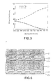
- the reflection factor R2 of the second information-storage layer 13 has a spectroscopic characteristic as shown in Fig. 5 such that the reflection factor is about 32 % with respect to light having the wavelength of 635 nm and substantially zero with respect to light having the wavelength of 780 nm. That is, the second information-storage layer 13 has somewhat refractivity with respect to light having the wavelength of 635 nm and permits light having the wavelength of 780 nm to substantially transmit therethrough.
- the first information-storage layer 12 (the A1 film) has a reflection factor of 80 % or higher with respect to both of the light beams which have penetrated the second information-storage layer 13. Therefore, the reflection factor R1 of the first information-storage layer 12 with respect to light having the wavelength of 780 nm which substantially penetrates the second information-storage layer 13 is about 84 % and the reflection factor R1 is about 36 % with respect to light having the wavelength of 635 nm which has substantially penetrated the second information-storage layer 13.
- the multilayer optical disk having the foregoing structure use of the reproducing light beam having the wavelength of 780 nm enables reflected light to be obtained from only the first information-storage layer 12 so that information signals are read from only the first information-storage layer 12.
- both of the first information-storage layer 12 and the second information-storage layer 13 have the reflection factor of 30 % or higher with respect to the reproducing light beam having the wavelength of 635 nm, information signals can be obtained from both of the layers 12 and 13.
- the positions of the focal points of the reproducing light beams By making the positions of the focal points of the reproducing light beams to be different from each other, information can be read from the two layers 12 and 13.
- this embodiment has a structure such that a second information-storage layer 23 is formed on a substrate 21 having a thickness of 0.6 mm; and a first information-storage layer 22 is formed on a second substrate 31 having a thickness of 0.6 mm, the two substrates 21 and 31 being then bonded to each other through a bonding adhesive layer 24 having light transmission properties.
- a multilayer optical disk according to this embodiment is constituted.
- Each of the substrates 21 and 31 is a polycarbonate substrate obtained by injection molding or a glass substrate manufactured by the 2P method.
- the structures of the information storage layers 22 and 23 are similar to those according to the first embodiment.
- a protective film 25 is formed on the first information-storage layer 22.
- reflected light was obtained from only the first information-storage layer 22 with respect to the reproducing light beam having the wavelength of 780 nm. With respect to the reproducing light beam having the wavelength of 635 nm, reflected light was obtained from the first information-storage layer 22 and the second information-storage layer 23.
- This embodiment may have another structure formed such that the first substrate and the second substrate are bonded to each other with the bonding adhesive layer 24 in such a manner that the first information-storage layer 22 and the second information-storage layer 23 face each other.
- this embodiment has a structure arranged such that a second information-storage layer 43 is formed on a first substrate 41 having a thickness of 1.2 mm, a first information-storage layer 42 is formed on a second substrate 51 having a thickness of 0.6 mm, and the first and second substrates 41 and 51 are, by a bonding adhesive layer 44, bonded to each other in such a manner that the information-storage layers 42 and 43 face each other.
- Each of the substrates 41 and 51 is a polycarbonate substrate formed by injection molding.
- the structure of each of the information storage layers 42 and 43 is similar to that of the first embodiment.
- reflected light was obtained from only the first information-storage layer 42 with respect to the reproducing light beam having the wavelength of 780 nm. With respect to the reproducing light beam having the wavelength of 635 nm, reflected light was obtained from both of the first information-storage layer 42 and second information-storage layer 43.
- this embodiment has the structure such that the first information-storage layer 42 and the second information-storage layer 43 are formed on the corresponding substrates 41 and 51, which are the polycarbonate substrates obtained by injection molding, a technique, such as the 2P method, is not required. Therefore, the multilayer optical disk according to this embodiment can significantly easily be manufactured.
- this embodiment has the structure arranged such that a first information-storage layer 62 was formed adjacent to a substrate 61, and then a second information-storage layer 63 was formed on the first information-storage layer 62 through a spacer layer 64.
- the second information-storage layer was an A1 film.
- the multilayer optical disk having the foregoing structure enabled a spectroscopic characteristic of the reflection factor as shown in Fig. 9 to be obtained.
- the reproducing light beam having the wavelength of 780 nm reflected light was obtained from only the first information-storage layer 62 as indicated by symbol R1 shown in Fig. 9.
- the first information-storage layer had the light transmission properties so that reflected light was obtained from the second information-storage layer 63 as indicated by symbol R2 shown in Fig. 9.
- a multilayer optical disk was manufactured which comprised a Si films each having a thickness of 14 nm, the Si films being formed into the first and second information storage layers. Then, the spectroscopic characteristic of the reflection factor of each Si film was measured.
- the reflection factor of each Si layer had no dependency upon the wavelength as shown in Fig. 10. Since the reflection factor is, in particular, low with respect to light having the wavelength of 780 nm, the compatibility with the compact disk and the like cannot be maintained.
- the present invention has the structure such that the information storage layer corresponding to the light beam having the wavelength of 780 nm is formed in a CD format that can be reproduced by a compact disk player.
- the information storage layer corresponding to only the light beam having the wavelength of 635 nm is recorded at a density higher than, for example, that of the CD format.
- a multilayer optical disk comprises a plurality of information storage layers, wherein one of said plural information storage layers has a reflection factor of 70% or higher with respect to a wavelength of 770 nm to 830 nm which is a first wavelength of reproducing light, and other information storage layers are reproduced with reproducing light having a second wavelength which is different from said first wavelength of reproducing light.
- Each of said other information storage layers has a reflection factor of 20% or higher with respect to said second wavelength of reproducing light.
- the second wavelength of reproducing light is 615 nm to 655 nm.
- a first information storage layer is reproduced with reproducing light having said first wavelength and a second information storage layer is reproduced with reproducing light having said second wavelength are formed on a substrate.
- a first substrate on which a first information storage layer is formed which is reproduced with reproducing light having said first wavelength and a second substrate on which a second information storage layer is formed which is reproduced with reproducing light having said second wavelength are bonded to each other. Both of an information signal recorded on said first information storage layer and an information signal recorded on said second information storage layer are reproduced with reproducing light having said second wavelength. Only an information signal recorded on said second information storage-layer is reproduced with reproducing light having said second wavelength.
- the second information storage layer is formed by a dielectric multilayer film.
- the second information storage layer is made of a semiconductor material having a band gap near a wavelength of 700 nm.
- the first information storage layer and the second information storage layer are laminated through a spacer layer having light transmission properties.
- the first information storage layer and the second information storage layer are, in this sequential order, laminated on said substrate.
- the second information storage layer and the first information storage layer are, in this sequential order laminated on said substrate.
- the plurality of information storage layers comprises a first information storage layer capable of transmitting one part of a first light beam having a wavelength of 615 nm to 655 nm and reflecting another part of said first light beam, a light transmitting layer formed on said first information storage layer, and a second information storage layer formed on said light transmitting layer and having a reflection factor of 70% or higher with respect to a second light beam having a wavelength of 770 nm to 830 nm.
- the first information storage layer contains SiN.
Abstract
1. An optical disc comprises a first information storing layer (13, 23, 43, 62) for reflecting a first laser beam and for transmitting a second laser beam, the wavelength of said second laser beam being shorter than the wavelength of said first laser beam, the information stored in said first information storing layer (13, 23, 43, 62) being read-out by said first laser beam, a second information storing layer (12, 22, 42, 63) for reflecting said second laser beam transmitted through said first information storing layer (13, 23, 43, 62), the information stored in said second information storing layer (12, 22, 42, 63) being read-out by said second laser beam, and a light incidence surface into which first and second laser beams are irradiated for reading-out the information from said first and second information storing layers (13, 23, 43, 62; 12, 22, 42, 63) respectively, said light incidence surface being formed at one side of said optical disc. The first information storing layer (13, 23, 43, 62) and the second information storing layer (12, 22, 42, 63) are provided to be optically separated for separating the reflected laser beam reflected by said first information storing layer (13, 23, 43, 62) and the reflected laser beam reflected by said second information storing layer (12, 22, 42, 63), and the length between said light incidence surface to said second information storing layer is substantially equal to the thickness of said optical disc.
Description
- The present invention relates to a multilayer optical disk having a multilayer structure consisting of a multiplicity of layers for storing information and thus capable of handling large-capacity information.
- In recent years, the prosperity of so-called multimedia results in a necessity of handling large-capacity information, such as a digital movie. Therefore, a necessity arises in that large-capacity information of the foregoing type must be stored and random-accessed so as to be reproduced, if need arises.
- An optical disk is a storage medium permitting random access, exhibiting a large capacity and capable of being ejected (being removable) from a regenerating apparatus. Therefore, the optical disks have been used in a variety of fields in a large quantity. In order to enlarge the capacity as described above, one side of the optical disk must be capable of handling large-capacity information.
- Under the foregoing circumstance, the capacity of the optical disk has been enlarged by a means attempted such that a multiplicity of layers for storing information are laminated in the direction of the thickness of the optical disk.
- A multilayer optical disk has a multilayer structure formed on one side thereof and consisting of information layers for storing information, wherein the focal points are made to be different from one another among the multiple layers so that information is read while maintaining random access characteristic and, therefore, large-capacity information is handled by a large capacity.
- Reported and representative multilayer optical disks will now be described.
- 1. A concept for reproducing the optical disk by making the positions of the focal points to be different from one another (refer to, for example, U.S. Patent No. 3,946,367).
- 2. A method using a multilayer disk having an information layer formed by laminating a plurality of layers on one side of the disk so that information is read by means of transmitted light or reflected light (refer to, for example, U.S. Patent No. 4,219,704).
- 3. A system for reproducing information from a multilayer optical disk, the system comprising an optical system having an aberration correction function (refer to U.S. Patent No. 5,202,875).
- In order to reproduce the conventional multilayer optical disk of the foregoing type, an exclusive apparatus for reproducing the optical disk is required. For example, there arises a requirement for a reproducing optical system capable of independently reproducing a reproduction signal from the first information storage layer or the second information storage layer without mixing. As an alternative to this, a signal processing system is required which is capable of distinguishing reproduction signals from the first information storage layer and the second information storage layer from each other so as to extract information without confusion.
- Therefore, a reproducing apparatus, such as a compact disk player for reproducing a so-called compact disk (CD) which has been used widely as a read-only optical disk, cannot be used as it is.
- Accordingly, an object of the present invention is to provide a novel multilayer optical disk having an information storage layer, which can as well as be reproduced by a general-purpose reproducing apparatus, such as a compact disk player, and enabling information to be read from the other information storage layers if an exclusive reproducing apparatus is used.
- In order to achieve the foregoing object, inventors of the present invention have energetically performed investigations for a long time. Thus, the spectroscopic characteristic of each information storage layer is contrived, thus resulting in that a novel multilayer optical disk being realized which is capable of detecting and reading information of an arbitrary information storage layer in accordance with the wavelengths of reproducing light and enabling a usual reproducing apparatus to read a signal supplied from any information storage layer, the usual reproducing apparatus being an apparatus which has been used widely.
- That is, the multilayer optical disk according to the present invention has a structure such that the reflection factor of one of the plural information storage layers with respect to a wavelength of 770 nm to 830 nm is made to be 70 % or higher and other information storage layers can be reproduced with a reproducing light beam having a wavelength different from the foregoing wavelength.
- Specifically, as shown in Fig. 1 for example, a first information-
storage layer 2 and a second information-storage layer 3 are formed on asubstrate 1. When the outer surface of thesubstrate 1 is irradiated with reproducing light under the following conditions: the first information-storage layer 2 has a reflection factor R1 of 70 % or higher with respect to a reproducing light beam having a wavelength of 770 nm to 830 nm; and the second information-storage layer 3 is transparent (has light transmission properties and has a low reflection factor R2) with respect to a reproducing light beam having the wavelength of 770 nm to 830 nm, and opaque (has low light transmission properties and has a high reflection factor R2) with respect to another reproducing light beam having another wavelength (a reproducing light beam having a second wavelength), only the first information-storage layer 2 can be read with the reproducing light beam having the wavelength of 770 nm to 830 nm. With the reproducing light beam having the second wavelength, only the second information-storage layer 3 or both of the first information-storage layer 2 and second information-storage layer 3 can be read. Whether the first information-storage layer 2 can be read with the reproducing light beam having the second wavelength depends upon the reflection factor R2 and the light transmission property characteristic of the second information-storage layer 3 with respect to the light beam having the second wavelength, the reflection factor R1 of the first information-storage layer 2 with respect to the light beam having the second wavelength, and the like. - The multilayer optical disk according to the present invention may, as well as the foregoing laminated structure (structure in which the information storage layers are laminated and formed on the substrate 1) employ, for example, a bonding structure. If the bonding structure is employed, image signal portions for the respective information storage layers can be formed by injection molding in place of the 2P method. Thus, an advantage can be obtained in manufacturing.
- When the multilayer optical disk having the foregoing structure is manufactured, the sequential laminating order of the information storage layer (the first information-storage layer having the reflection factor of R1) having the reflection factor of 70 % or higher with respect to the wavelength of 770 nm to 830 nm and the information storage layer (the second information-storage layer having the reflection factor of R2) which can be read with the second wavelength of the light beam may be determined arbitrarily. If the first information-storage layer is formed adjacent to the substrate (adjacent to the portion irradiated with the reproducing light beam), also the first information-storage layer is required to have the spectroscopic characteristic and somewhat light transmission properties with respect to the second wavelength of the reproducing beam. If the first information-storage layer is formed in the rear of the second information-storage layer, only the reflection factor with respect to the wavelength of 770 nm to 830 nm is required to be considered. Therefore, a metal film, such as an AL film, having a high reflection factor may be employed.
- Since the first information-storage layer is an information storage layer having a compatibility with the compact disk, it is preferable that the first information-storage layer be formed at a position about 1.2 mm apart from the surface to be irradiated with the reproducing light beam in order to attain the optical compatibility. Therefore, when the respective information storage layers are formed on, for example, the
substrate 1, it is preferable that the thickness of each information storage layer be about 1.2 mm. - On the other hand, the second information-storage layer must have the spectroscopic characteristic as described above. Therefore, for example, a dielectric multilayer film or a film having a band gap near 700 nm and made of a semiconductor laser material may be employed. The semiconductor laser material is exemplified by AlxGa(1-x)As, GaAs(1-x)Px and ZnxCd(1-x)Se.
- A spacer layer for optically separating the foregoing information storage layers from one another may be formed between the respective information storage layers. It is preferable that the spacer layer be formed by a material having light transmission properties. In order to reliably perform the foregoing optical separation, it is preferable that the thickness of the spacer layer be 30 mm or thicker.
- To read information signals recorded on the multilayer optical disk, a reproducing light beam having the wavelength of 780 nm is employed as the first reproducing light beam and a reproducing light beam having another wavelength is employed as the second reproducing light beam. The wavelength of the second reproducing light beam may be determined arbitrarily if the wavelength is different from that of the first reproducing light beam. To attain the foregoing selectivity, it is preferable that the wavelengths be different from each other to a certain extent. If an advantage is required in practical use, it is preferable that a reproducing light beam having a wavelength of about 635 ± 20 nm be employed. In the case where the second reproducing light beam is used to read information signals from both of the first information-storage layer and second information-storage layer, the positions of the focal points of the information storage layers are required to be made to be different from one another so as to read the information signals from the respective information storage layers.
- The multilayer optical disk according to the present invention comprising the plural information storage layers has a structure such that one of the information storage layers has the reflection factor of 70 % or higher with respect to the wavelength of 770 nm to 830 nm which is the first wavelength of the reproducing light beam.
- Therefore, the foregoing information storage layer has a compatibility with so-called compact disks (music compact disks and ROM disks for computers, that is, CD-ROMs). Also the information signals recorded on the foregoing information storage layer can be reproduced by a reproducing apparatus, such as a compact disk player.
- On the other hand, the second wavelength of the reproducing beam which is different from the first wavelength of the reproducing beam is able to reproduce information signals recorded on only the second information-storage layer or information signals from both of the first information-storage layer and second information-storage layer.
- That is, according to the present invention, information from the first information-storage layer and second information-storage layer can be selected by changing the wavelength of the reproducing light beam so that information is stored in a large capacity.
-
- Fig. 1 is a schematic view showing the basic structure of a multilayer optical disk according to the present invention;
- Fig. 2 is a schematic cross sectional view showing essential portions of an example of the structure of the multilayer optical disk according to the present invention;
- Fig. 3 is a graph showing the spectroscopic characteristic of the reflection factor of the multilayer optical disk shown in Fig. 2;
- Fig. 4 is a graph showing the spectroscopic characteristic of the reflection factor of a multilayer optical disk having a second information-storage layer formed into a triple-layer structure;
- Fig. 5 is a graph showing the spectroscopic characteristic of the reflection factor of a multilayer optical disk having a second information-storage layer formed into a semiconductor layer material film;
- Fig. 6 is a schematic cross sectional view showing essential portions of an example of a multilayer optical disk having a structure comprising two substrates bonded to each other;
- Fig. 7 is a schematic cross sectional view showing essential portions of another example of the multilayer optical disk having a structure comprising two substrates bonded to each other;
- Fig. 8 is a schematic cross sectional view showing essential portions of a multilayer optical disk having a first information-storage layer formed adjacent to the substrate and formed by a triple-layer structure film;
- Fig. 9 is a graph showing the spectroscopic characteristic of the reflection factor of the multilayer optical disk shown in Fig. 7; and
- Fig. 10 is a graph showing the spectroscopic characteristic of the reflection factor of a multilayer optical disk having two information storage layers which are Si films.
- Preferred embodiments of the present invention will now be described in detail with reference to the drawings.
- As shown in Fig. 2, a multilayer optical disk according to this embodiment has a structure such that a second information-
storage layer 13, aspacer layer 14 and a first information-storage layer 12 are, in this sequential order, formed on a substrate 11. - The substrate 11 is made of, for example, polycarbonate or glass. If the substrate 11 is made of polycarbonate, a so-called 2P method is employed in such a manner that a projection and pit pattern, such as recording pits, is formed as information to be exclusively reproduced. In this embodiment, a polycarbonate substrate having a thickness of 1.2 mm and made by injection molding is employed.
- The second information-
storage layer 13 is formed along the projection and pit pattern of the substrate 11 to reflect a portion of light beams made incident upon the substrate 11 and permit a portion of the light beam to transmit therethrough. Thus, the second information-storage layer 13 serves as a reflecting film for reading information in the form of the projection and pit pattern to be exclusively reproduced. - The
spacer layer 14 is formed to optically separate the second information-storage layer 13 and the first information-storage layer 12 from each other. Therefore, thespacer layer 14 must have a certain thickness. Specifically, it is preferable that thespacer layer 14 be 30 mm or thicker. If thespacer layer 14 is too thin, light reflected by the first information-storage layer 12 and that reflected by the second information-storage layer 13 cannot sufficiently be separated from each other and, therefore, accurate detection cannot easily be performed. If thespacer layer 14 is too thick, spherical aberration and the like take place. Therefore, the thickness must be determined appropriately to prevent the foregoing problems. - The first information-
storage layer 12 formed on the second information-storage layer 13 through thespacer layer 14 is made of a material having a high reflection factor. The reflection factor of the first information-storage layer 12 is 70 % or higher with respect to the wavelength of 770 nm to 830 nm. - To manufacture the foregoing multilayer optical disk, the substrate 11 is prepared initially, the substrate 11 having the projection and pit pattern, such as pits, formed to correspond to information signals to be read from the second information-
storage layer 13. The substrate 11 may be made of either glass or plastic such as polycarbonate plastic. In the case where the glass substrate is employed, a so-called 2P (Photo Polymerization) method or the like is performed with which photosetting resin is enclosed between the glass substrate and a disk stamper, and then the photosetting resin is irradiated with light from a position on the outside of the glass substrate so that the projection and pit pattern is formed. Also in the case of the plastic substrate, the projection and pit pattern may be formed by the 2P method. However, an injection molding method using a stamper is generally employed to form the projection and pit pattern. - The second information-
storage layer 13 is, on the substrate 11, formed by a vacuum evaporation method or a sputtering method. - Then, the
spacer layer 14 is formed on the second information-storage layer 13. Since thespacer layer 14 must have a certain thickness, for example, a thickness of 30 µm or more, thespacer layer 14 is formed by applying ultraviolet-curing resin or the like by a spin coating method. Thespacer layer 14 may be formed into a laminated shape by plural times of the laminating processes in each of which a layer having a thickness of µm to 10 µm is formed. Thespacer layer 14 may be formed by bonding a transparent sheet. - Also the
spacer layer 14 must have pits or the like formed to correspond to the information signals to be recorded on the first information-storage layer 12. The foregoing pits can be formed by the 2P method similar to the foregoing projection and pit pattern. - After the
spacer layer 14 has been formed, the first information-storage layer 12 is formed on thespacer layer 14. Then, if necessary, aprotective film 15 is formed by ultraviolet-curing resin or the like. - In this embodiment, the second information-
storage layer 13 on the substrate 11 is in the form of a five-layer structure film consisting of Si3N4/ SiO2/ Si3N4/ SiO2/Si3N4layers. The five layers respectively have thicknesses of64 nm/90 nm/64 nm/90 nm/64 nm. - The refractive index n of Si3N4 is 2.0 and the extinction coefficient k of the same is 0, while the refractive index n of SiO2 is 1.5 and the extinction coefficient k of the same is 0. As a matter of course, materials having similar optical characteristics may be employed to obtain a similar characteristic.
- The first information-
storage layer 12 is an A1 film having a thickness of 100 nm. - In the thus-structured multilayer optical disk, the reflection factor R2 of the second information-storage layer 13 (the five-layer structure film) has a spectroscopic characteristic as shown in Fig. 3 such that the reflection factor R2 is 34 % with respect to light having a wavelength of 635 nm; and the reflection factor R2 is substantially zero with respect to light having the wavelength of 780 nm. That is, the second information-
storage layer 13 has somewhat refractivity with respect to light having the wavelength of 635 nm and permits light having the wavelength of 780 nm to substantially transmit therethrough. - On the other hand, the first information-storage layer 12 (the A1 film) has a reflection factor of 80 % or higher with respect to both of light beams which have penetrated the second information-
storage layer 13. Therefore, the reflection factor R1 of the first information-storage layer 12 with respect to the reproducing light beam is about 84 % with respect to light having the wavelength of 780 nm which substantially penetrates the second information-storage layer 13 and about 38 % with respect to light having the wavelength of 635 nm which has somewhat penetrated the second information-storage layer 13. - With the multilayer optical disk having the foregoing structure, use of the reproducing light beam having the wavelength of 780 nm enables reflected light to be obtained from only the first information-
storage layer 12 so that information signals recorded on the first information-storage layer 12 are read. Since the reproducing light beam having the wavelength of 780 nm is used in the compact disk player and the like, the information signals recorded on the first information-storage layer 12 can as well as be reproduced by the foregoing general-purpose reproducing apparatus. - Since both of the first information-
storage layer 12 and the second information-storage layer 13 have the reflection factor of about 30 % with respect to the reproducing light beam having the wavelength of 635 nm, information signals can be obtained from the twolayers storage layer 12 and the second information-storage layer 13. - A multilayer optical disk was manufactured which comprised a second information-
storage layer 13 in the form of a triple-layer structure film and other layers respectively having structures similar to those of the first embodiment. Note that the second information-storage layer 13 was in the form of a triple-layer structure film, the triple layers respectively being made of SixN(1-x)(n = 2.8 and k = 0)/Si3N4 (n = 2 and k = 0)/SixN(1-x)(n = 2.8 and k = 0). The thicknesses of the respective layers were 40 nm/73 nm/40 nm. - Also in this embodiment, the reflection factor R1 of the first information-
storage layer 12 and the reflection factor R2 of the second information-storage layer 13 have the spectroscopic characteristics as shown in Fig. 4. With the reproducing light beam having the wavelength of 780 nm, only the information signals recorded on the first information-storage layer 12 can be read. With the reproducing light beam having the wavelength of 635 nm, information signals can be read from both of the first information-storage layer 12 and the second information-storage layer 13. - In this embodiment, the second information-
storage layer 13 is made of AlxGa(1-x)As which is a semiconductor laser material and which has a thickness of 120 nm. - The first information-
storage layer 12 is an A1 film having a thickness of 100 nm. The other structures are the same as those according to the first embodiment. - In the multilayer optical disk structured as described above, the reflection factor R2 of the second information-
storage layer 13 has a spectroscopic characteristic as shown in Fig. 5 such that the reflection factor is about 32 % with respect to light having the wavelength of 635 nm and substantially zero with respect to light having the wavelength of 780 nm. That is, the second information-storage layer 13 has somewhat refractivity with respect to light having the wavelength of 635 nm and permits light having the wavelength of 780 nm to substantially transmit therethrough. - On the other hand, the first information-storage layer 12 (the A1 film) has a reflection factor of 80 % or higher with respect to both of the light beams which have penetrated the second information-
storage layer 13. Therefore, the reflection factor R1 of the first information-storage layer 12 with respect to light having the wavelength of 780 nm which substantially penetrates the second information-storage layer 13 is about 84 % and the reflection factor R1 is about 36 % with respect to light having the wavelength of 635 nm which has substantially penetrated the second information-storage layer 13. - With the multilayer optical disk having the foregoing structure, use of the reproducing light beam having the wavelength of 780 nm enables reflected light to be obtained from only the first information-
storage layer 12 so that information signals are read from only the first information-storage layer 12. On the other hand, since both of the first information-storage layer 12 and the second information-storage layer 13 have the reflection factor of 30 % or higher with respect to the reproducing light beam having the wavelength of 635 nm, information signals can be obtained from both of thelayers layers - As shown in Fig. 6, this embodiment has a structure such that a second information-
storage layer 23 is formed on asubstrate 21 having a thickness of 0.6 mm; and a first information-storage layer 22 is formed on asecond substrate 31 having a thickness of 0.6 mm, the twosubstrates bonding adhesive layer 24 having light transmission properties. Thus, a multilayer optical disk according to this embodiment is constituted. - Each of the
substrates protective film 25 is formed on the first information-storage layer 22. - Also with the multilayer optical disk having the foregoing structure, similar to the first embodiment, reflected light was obtained from only the first information-
storage layer 22 with respect to the reproducing light beam having the wavelength of 780 nm. With respect to the reproducing light beam having the wavelength of 635 nm, reflected light was obtained from the first information-storage layer 22 and the second information-storage layer 23. - This embodiment may have another structure formed such that the first substrate and the second substrate are bonded to each other with the bonding
adhesive layer 24 in such a manner that the first information-storage layer 22 and the second information-storage layer 23 face each other. - As shown in Fig. 7, this embodiment has a structure arranged such that a second information-
storage layer 43 is formed on afirst substrate 41 having a thickness of 1.2 mm, a first information-storage layer 42 is formed on asecond substrate 51 having a thickness of 0.6 mm, and the first andsecond substrates adhesive layer 44, bonded to each other in such a manner that the information-storage layers - Each of the
substrates - Also with the multilayer optical disk having the foregoing structure, similar to the first embodiment, reflected light was obtained from only the first information-
storage layer 42 with respect to the reproducing light beam having the wavelength of 780 nm. With respect to the reproducing light beam having the wavelength of 635 nm, reflected light was obtained from both of the first information-storage layer 42 and second information-storage layer 43. - Since this embodiment has the structure such that the first information-
storage layer 42 and the second information-storage layer 43 are formed on the correspondingsubstrates - As shown in Fig. 8, this embodiment has the structure arranged such that a first information-
storage layer 62 was formed adjacent to asubstrate 61, and then a second information-storage layer 63 was formed on the first information-storage layer 62 through aspacer layer 64. - The first information-
storage layer 62 consists of three layers which respectively are made of SixN(1-x)(n = 3.5 and k = 0)/SiO2(n = 1.5 and k = 0)/SixN(1-x)(n = 3.5 and k = 0) respectively having thicknesses of 45 nm/195 nm/45 nm. - The second information-storage layer was an A1 film.
- Also the multilayer optical disk having the foregoing structure enabled a spectroscopic characteristic of the reflection factor as shown in Fig. 9 to be obtained. With respect to the reproducing light beam having the wavelength of 780 nm, reflected light was obtained from only the first information-
storage layer 62 as indicated by symbol R1 shown in Fig. 9. With respect to the reproducing light beam having the wavelength of 635 nm, the first information-storage layer had the light transmission properties so that reflected light was obtained from the second information-storage layer 63 as indicated by symbol R2 shown in Fig. 9. - A multilayer optical disk was manufactured which comprised a Si films each having a thickness of 14 nm, the Si films being formed into the first and second information storage layers. Then, the spectroscopic characteristic of the reflection factor of each Si film was measured.
- As a result, the reflection factor of each Si layer had no dependency upon the wavelength as shown in Fig. 10. Since the reflection factor is, in particular, low with respect to light having the wavelength of 780 nm, the compatibility with the compact disk and the like cannot be maintained.
- Note that the present invention has the structure such that the information storage layer corresponding to the light beam having the wavelength of 780 nm is formed in a CD format that can be reproduced by a compact disk player. On the other hand, the information storage layer corresponding to only the light beam having the wavelength of 635 nm is recorded at a density higher than, for example, that of the CD format.
- Although the invention has been described in its preferred form with a certain degree of particularity, it is understood that the present disclosure of the preferred form can be changed in the details of construction and in the combination and arrangement of parts without departing from the spirit and the scope of the invention as hereinafter claimed.
- A multilayer optical disk comprises a plurality of information storage layers, wherein one of said plural information storage layers has a reflection factor of 70% or higher with respect to a wavelength of 770 nm to 830 nm which is a first wavelength of reproducing light, and other information storage layers are reproduced with reproducing light having a second wavelength which is different from said first wavelength of reproducing light. Each of said other information storage layers has a reflection factor of 20% or higher with respect to said second wavelength of reproducing light. The second wavelength of reproducing light is 615 nm to 655 nm. A first information storage layer is reproduced with reproducing light having said first wavelength and a second information storage layer is reproduced with reproducing light having said second wavelength are formed on a substrate. A first substrate on which a first information storage layer is formed which is reproduced with reproducing light having said first wavelength and a second substrate on which a second information storage layer is formed which is reproduced with reproducing light having said second wavelength are bonded to each other. Both of an information signal recorded on said first information storage layer and an information signal recorded on said second information storage layer are reproduced with reproducing light having said second wavelength. Only an information signal recorded on said second information storage-layer is reproduced with reproducing light having said second wavelength. The second information storage layer is formed by a dielectric multilayer film. The second information storage layer is made of a semiconductor material having a band gap near a wavelength of 700 nm. The first information storage layer and the second information storage layer are laminated through a spacer layer having light transmission properties. The first information storage layer and the second information storage layer are, in this sequential order, laminated on said substrate. The second information storage layer and the first information storage layer are, in this sequential order laminated on said substrate. In a multilayer optical disk comprising a plurality of information storage layers on a substrate, the plurality of information storage layers comprises a first information storage layer capable of transmitting one part of a first light beam having a wavelength of 615 nm to 655 nm and reflecting another part of said first light beam, a light transmitting layer formed on said first information storage layer, and a second information storage layer formed on said light transmitting layer and having a reflection factor of 70% or higher with respect to a second light beam having a wavelength of 770 nm to 830 nm. The first information storage layer contains SiN.
Claims (13)
- An optical disc comprising:a first information storing layer (13, 23, 43, 62) for reflecting a first laser beam and for transmitting a second laser beam, the wavelength of said second laser beam being shorter than the wavelength of said first laser beam, the information stored in said first information storing layer (13, 23, 43, 62) being read-out by said first laser beam;a second information storing layer (12, 22, 42, 63) for reflecting said second laser beam transmitted through said first information storing layer (13, 23, 43, 62), the information stored in said second information storing layer (12, 22, 42, 63) being read-out by said second laser beam; anda light incidence surface into which first and second laser beams are irradiated for reading-out the information from said first and second information storing layers (13, 23, 43, 62; 12, 22, 42, 63) respectively, said light incidence surface being formed at one side of said optical disc, whereinsaid first information storing layer (13, 23, 43, 62) and said second information storing layer (12, 22, 42, 63) are provided to be optically separated for separating the reflected laser beam reflected by said first information storing layer (13, 23, 43, 62) and the reflected laser beam reflected by said second information storing layer (12, 22, 42, 63), and the length between said light incidence surface to said second information storing layer is substantially equal to the thickness of said optical disc.
- An optical disc according to claim 1, wherein the length between said light incidence surface and said second information storing layer (12, 22, 42, 63) is substantially equal to 1.2 mm and the length between said light incidence surface and said first information storing layer (13, 23, 43, 62) is substantially equal to 0.6 mm.
- An optical disc according to claim 1 or 2, further comprising a spacer layer 814, 44, 64) made by a transparent material and arranged between said first information storing layer (13, 23, 43, 62) and said second information storing layer (12, 22, 42, 63).
- An optical disc according to claim 1, wherein the reflectivity of said first information storing layer (13, 23, 43, 62) to said first laser beam at 635 nm is about 30 % and the reflectivity of said second information storing layer (12, 22, 42, 63) to said second laser beam at 780 - 830 nm is 70 % or higher.
- An optical disc according to claim 1, said optical disc further comprising a first substrate (11, 21, 41, 61) and a second substrate (15, 31, 51, 65), said light incidence surface being one of the surfaces of said first substrate, and the other surface of said first substrate being formed on said first information storing layer, one of the surfaces of said second substrate being formed on said second information storing layer, and the thickness of said first and second substrate being substantially equal to 0.6 mm.
- An optical disc according to claim 5, wherein said first substrate and said second substrates are bonded together.
- An optical disc according to claim 5, wherein the other surface of said second substrate (31) is bonded with said other surface of said first substrate (21) via said first information storing layer (23).
- An optical disc according to anyone of claims 1 to 7, wherein information stored in said second information storing layer has compatibility of CD format.
- An optical disc according to claim 3, wherein the thickness of said spacer layer is 30 µm or greater.
- An optical disc according to anyone of claims 1 to 9, wherein the reflectivity of said second information storing layer to said first laser beam is lower than the reflectivity to said second laser beam.
- An optical disc reading-out method, said optical disc comprising a first information storing layer (13, 23, 43, 62) for reflecting a first laser beam and for transmitting a second laser beam, the wavelength of said second laser beam being shorter than the wavelength of said first laser beam, a second information storing layer (12, 22, 42, 63) for reflecting said second laser beam transmitted through said first information storing layer and a light incidence surface into which said first and second laser beams are irradiated for reading-out the information from said first and second information storing layers respectively, said light incidence surface being formed at one side of said optical disc, wherein said first information storing layer and said second information storing layer are provided to be optical separated for separating the reflected laser beam reflected by said first information storing layer and the reflected laser beam reflected by said second information storing layer, and the length between said light incidence surface to said second information storing layer is substantially equal to the thickness of said optical disc, said reading-out method comprising in steps of:irradiating said first laser beam to said optical disc; andchanging a focus point of said first laser beam between said first and second information storing layers and reading-out the information from the respective information storing layer.
- An optical disc reading-out method according to claim 11, wherein the wavelength of said first laser is 635 nm.
- An optical disc reading-out method according to claim 12, wherein the information having a compatibility of CD format is stored in said second information storing layer.
Applications Claiming Priority (5)
| Application Number | Priority Date | Filing Date | Title |
|---|---|---|---|
| JP8536995 | 1995-04-11 | ||
| JP8536995 | 1995-04-11 | ||
| JP9406895 | 1995-04-19 | ||
| JP9406895A JPH08339574A (en) | 1995-04-11 | 1995-04-19 | Multilayered optical disk |
| EP19960105641 EP0737966B1 (en) | 1995-04-11 | 1996-04-10 | Multilayer optical disk |
Related Parent Applications (2)
| Application Number | Title | Priority Date | Filing Date |
|---|---|---|---|
| EP96105641.3 Division | 1996-04-10 | ||
| EP19960105641 Division EP0737966B1 (en) | 1995-04-11 | 1996-04-10 | Multilayer optical disk |
Publications (1)
| Publication Number | Publication Date |
|---|---|
| EP1168319A1 true EP1168319A1 (en) | 2002-01-02 |
Family
ID=26426386
Family Applications (2)
| Application Number | Title | Priority Date | Filing Date |
|---|---|---|---|
| EP20010118988 Withdrawn EP1168319A1 (en) | 1995-04-11 | 1996-04-10 | Multilayer optical disk |
| EP19960105641 Expired - Lifetime EP0737966B1 (en) | 1995-04-11 | 1996-04-10 | Multilayer optical disk |
Family Applications After (1)
| Application Number | Title | Priority Date | Filing Date |
|---|---|---|---|
| EP19960105641 Expired - Lifetime EP0737966B1 (en) | 1995-04-11 | 1996-04-10 | Multilayer optical disk |
Country Status (9)
| Country | Link |
|---|---|
| US (4) | US5766717A (en) |
| EP (2) | EP1168319A1 (en) |
| JP (1) | JPH08339574A (en) |
| KR (2) | KR100432144B1 (en) |
| CN (2) | CN1092381C (en) |
| DE (1) | DE69628610T2 (en) |
| MY (2) | MY128223A (en) |
| SG (1) | SG50644A1 (en) |
| TW (1) | TW307864B (en) |
Families Citing this family (54)
| Publication number | Priority date | Publication date | Assignee | Title |
|---|---|---|---|---|
| US5726969A (en) * | 1994-12-28 | 1998-03-10 | Matsushita Electric Industrial Co., Ltd. | Optical recording medium having dual information surfaces |
| JPH08339574A (en) * | 1995-04-11 | 1996-12-24 | Sony Corp | Multilayered optical disk |
| USRE40136E1 (en) * | 1995-04-11 | 2008-03-04 | Sony Corporation | Multilayer optical disk |
| JP3008819B2 (en) * | 1995-05-31 | 2000-02-14 | 日本ビクター株式会社 | optical disk |
| JPH0917119A (en) * | 1995-06-30 | 1997-01-17 | Sony Corp | Data recording medium, data recording method and data reproducing method |
| WO1997009716A1 (en) * | 1995-09-08 | 1997-03-13 | Philips Electronics N.V. | Optical multilayer information carrier |
| FR2750528A1 (en) * | 1996-06-28 | 1998-01-02 | Thomson Multimedia Sa | OPTICAL DISC COMPATIBLE WITH TWO DIFFERENT READING SYSTEMS |
| JPH113541A (en) * | 1997-06-11 | 1999-01-06 | Sony Corp | Optical disk and manufacture thereof |
| KR100242129B1 (en) * | 1997-06-18 | 2000-02-01 | 윤종용 | Optical disk satis fying plural standards |
| KR100425084B1 (en) * | 1997-06-18 | 2004-07-21 | 엘지전자 주식회사 | Optical disk recording medium and reproducing apparatus capable of reading data without accurate focusing and recording data without efm |
| JP3867347B2 (en) * | 1997-06-20 | 2007-01-10 | ソニー株式会社 | Multi-layer optical disc |
| KR100268486B1 (en) * | 1997-11-01 | 2000-10-16 | 윤종용 | Method and apparatus for recording information on optical disc with characteristic of wavelength and reproducing from the optical disc |
| JPH11296904A (en) * | 1998-04-03 | 1999-10-29 | Toshiba Corp | Information recording medium and manufacture of resin substrate used for the same |
| US6379767B1 (en) * | 1998-04-28 | 2002-04-30 | Lg Electronics Inc. | Optical recording medium with multiple recording layers and fabricating method thereof |
| US7045187B2 (en) | 1998-06-22 | 2006-05-16 | Nee Han H | Metal alloys for the reflective or the semi-reflective layer of an optical storage medium |
| US7314657B2 (en) | 2000-07-21 | 2008-01-01 | Target Technology Company, Llc | Metal alloys for the reflective or the semi-reflective layer of an optical storage medium |
| US6905750B2 (en) | 1998-06-22 | 2005-06-14 | Target Technology Company, Llc | Metal alloys for the reflective or the semi-reflective layer of an optical storage medium |
| US7384677B2 (en) | 1998-06-22 | 2008-06-10 | Target Technology Company, Llc | Metal alloys for the reflective or semi-reflective layer of an optical storage medium |
| US6007889A (en) * | 1998-06-22 | 1999-12-28 | Target Technology, Llc | Metal alloys for the reflective or the semi-reflective layer of an optical storage medium |
| US6852384B2 (en) | 1998-06-22 | 2005-02-08 | Han H. Nee | Metal alloys for the reflective or the semi-reflective layer of an optical storage medium |
| US6790503B2 (en) | 1998-06-22 | 2004-09-14 | Target Technology Company, Llc | Metal alloys for the reflective or the semi-reflective layer of an optical storage medium |
| US6764735B2 (en) | 1998-06-22 | 2004-07-20 | Target Technology Company, Llc | Metal alloys for the reflective or the semi-reflective layer of an optical storage medium |
| TW468179B (en) * | 1998-08-05 | 2001-12-11 | Matsushita Electric Ind Co Ltd | Optical recording medium |
| DE19923542A1 (en) | 1999-05-21 | 2001-01-18 | Thomson Brandt Gmbh | Optical record carrier |
| EP1137003A4 (en) * | 1999-08-18 | 2003-07-23 | Sony Corp | Optical recording medium, and method and apparatus for reproduction |
| US7065035B1 (en) * | 1999-10-25 | 2006-06-20 | Matsushita Electric Industrial Co., Ltd. | Optical multilayer disk, multiwavelength light source, and optical system using them |
| KR100694410B1 (en) * | 2000-03-30 | 2007-03-12 | 엘지전자 주식회사 | Multilayered optical disc and method for driving a multilayered optical disc |
| EP1162614A3 (en) * | 2000-06-09 | 2006-04-05 | TDK Corporation | Optical information medium |
| US7374805B2 (en) | 2000-07-21 | 2008-05-20 | Target Technology Company, Llc | Metal alloys for the reflective or the semi-reflective layer of an optical storage medium |
| US7316837B2 (en) | 2000-07-21 | 2008-01-08 | Target Technology Company, Llc | Metal alloys for the reflective or the semi-reflective layer of an optical storage medium |
| US7314659B2 (en) | 2000-07-21 | 2008-01-01 | Target Technology Company, Llc | Metal alloys for the reflective or semi-reflective layer of an optical storage medium |
| JP2003051140A (en) | 2001-08-06 | 2003-02-21 | Sanyo Electric Co Ltd | Optical disk and method of manufacturing the same |
| DE10150025A1 (en) * | 2001-10-11 | 2003-04-17 | Dieter Dierks | Hybrid CD-DVD disk, in which the reading light beams for one data format pass through the information layers for the other data format, allowing a thinner disk to be obtained and a higher CD data density to be achieved |
| JP2003281791A (en) * | 2002-03-22 | 2003-10-03 | Toshiba Corp | Single-sided two layered optical disk and method and device for manufacturing the same |
| US7572517B2 (en) | 2002-07-08 | 2009-08-11 | Target Technology Company, Llc | Reflective or semi-reflective metal alloy coatings |
| DE10252339A1 (en) * | 2002-11-11 | 2004-05-19 | Stefan Schreiber | Two-sided optical disc with audio content, has Super Audio CD data format on one side and a physically- or logically-differing data format on other side |
| ES2297234T3 (en) * | 2002-12-13 | 2008-05-01 | Koninklijke Philips Electronics N.V. | DOUBLE BATTERY OPTICAL DATA STORAGE MEDIA AND THE USE OF THIS MEDIA. |
| JP2006523913A (en) | 2003-04-18 | 2006-10-19 | ターゲット・テクノロジー・カンパニー・エルエルシー | Alloys for reflective or semi-reflective layers of light storage media |
| US7343210B2 (en) * | 2003-07-02 | 2008-03-11 | James Devito | Interactive digital medium and system |
| WO2005004684A1 (en) * | 2003-07-15 | 2005-01-20 | Koninklijke Philips Electronics N.V. | Beverage maker suitable for use at high altitudes |
| WO2005010874A1 (en) * | 2003-07-25 | 2005-02-03 | Koninklijke Philips Electronics N.V. | Hybrid recordable optical record carrier |
| DE10351166A1 (en) * | 2003-11-03 | 2005-06-16 | Stefan Schreiber | Hybrid optical disc with modified CD layer |
| JP2006031841A (en) * | 2004-07-16 | 2006-02-02 | Sony Corp | Multilayer optical recording medium |
| US20060075419A1 (en) * | 2004-10-06 | 2006-04-06 | Tdk Corporation | Information recording medium |
| JP2006155830A (en) | 2004-11-30 | 2006-06-15 | Memory Tec Kk | Optical disk, optical disk apparatus, and optical disk play back method |
| WO2006080964A1 (en) * | 2005-01-25 | 2006-08-03 | Thomson Licensing | High density, hybrid optical disc |
| KR100694411B1 (en) * | 2005-03-30 | 2007-03-12 | 엘지전자 주식회사 | Multilayered recording media and writing or replaying method therdof |
| KR20060105233A (en) * | 2005-04-02 | 2006-10-11 | 삼성전자주식회사 | Hybrid disc and recording and/or reproducing apparatus and method for the same |
| JP2006313585A (en) * | 2005-05-06 | 2006-11-16 | Toshiba Corp | Optical disk, manufacturing method of optical disk, information reproducing device, information reproducing method, information recording device, and information recording method |
| US20060273866A1 (en) * | 2005-06-07 | 2006-12-07 | Nokia Corporation | Film bulk acoustic wave resonator with differential topology |
| US20070007357A1 (en) * | 2005-07-08 | 2007-01-11 | Oc Oerlikon Balzers Ag | Wavelength-selective metal dielectric filter and its application to optical discs |
| US20070224385A1 (en) * | 2005-07-08 | 2007-09-27 | Oc Oerlikon Balzers Ag | Wavelength selective dielectric filter and its application to optical disks |
| US9280863B2 (en) * | 2008-07-16 | 2016-03-08 | Parata Systems, Llc | Automated dispensing system for pharmaceuticals and other medical items |
| TWI665665B (en) * | 2014-02-14 | 2019-07-11 | 日商新力股份有限公司 | Optical recording medium with plural recording layers capable of suppressing off track |
Citations (3)
| Publication number | Priority date | Publication date | Assignee | Title |
|---|---|---|---|---|
| EP0368442A2 (en) * | 1988-11-08 | 1990-05-16 | Pioneer Electronic Corporation | Optical information record carrier and the method of producing the same |
| EP0520619A1 (en) * | 1991-06-28 | 1992-12-30 | Pioneer Electronic Corporation | Optical information recording medium |
| EP0605924A2 (en) * | 1993-01-04 | 1994-07-13 | Koninklijke Philips Electronics N.V. | Multiplane information storage system and record carrier for use in such a system |
Family Cites Families (13)
| Publication number | Priority date | Publication date | Assignee | Title |
|---|---|---|---|---|
| NL7803069A (en) * | 1978-03-22 | 1979-09-25 | Philips Nv | MULTI-LAYER INFORMATION DISK. |
| NL8702493A (en) * | 1986-10-31 | 1988-05-16 | Seiko Epson Corp | OPTICAL RECORDING MEDIUM AND METHOD FOR MAKING THEREOF |
| JP2657579B2 (en) * | 1990-04-19 | 1997-09-24 | 富士写真フイルム株式会社 | Optical information recording medium |
| JPH06309695A (en) * | 1993-04-20 | 1994-11-04 | Ricoh Co Ltd | Optical information recording medium and recording and erasing method thereof |
| JPH0721602A (en) * | 1993-06-30 | 1995-01-24 | Fujitsu Ltd | Magneto-optical recording medium |
| US5502595A (en) * | 1994-06-03 | 1996-03-26 | Industrial Technology Research Institute | Color filters and their preparation |
| US5540966A (en) * | 1994-08-05 | 1996-07-30 | Minnesota Mining And Manufacturing Company | Dual layer optical medium having partially reflecting thin film layer |
| US5526338A (en) * | 1995-03-10 | 1996-06-11 | Yeda Research & Development Co. Ltd. | Method and apparatus for storage and retrieval with multilayer optical disks |
| JPH08339574A (en) * | 1995-04-11 | 1996-12-24 | Sony Corp | Multilayered optical disk |
| JP3210549B2 (en) * | 1995-05-17 | 2001-09-17 | 日本コロムビア株式会社 | Optical information recording medium |
| KR100242129B1 (en) * | 1997-06-18 | 2000-02-01 | 윤종용 | Optical disk satis fying plural standards |
| JP3867347B2 (en) * | 1997-06-20 | 2007-01-10 | ソニー株式会社 | Multi-layer optical disc |
| US6007889A (en) * | 1998-06-22 | 1999-12-28 | Target Technology, Llc | Metal alloys for the reflective or the semi-reflective layer of an optical storage medium |
-
1995
- 1995-04-19 JP JP9406895A patent/JPH08339574A/en active Pending
-
1996
- 1996-04-06 MY MYPI20024818A patent/MY128223A/en unknown
- 1996-04-06 MY MYPI96001317A patent/MY115010A/en unknown
- 1996-04-09 US US08/629,564 patent/US5766717A/en not_active Expired - Lifetime
- 1996-04-10 EP EP20010118988 patent/EP1168319A1/en not_active Withdrawn
- 1996-04-10 SG SG1996007571A patent/SG50644A1/en unknown
- 1996-04-10 KR KR1019960010739A patent/KR100432144B1/en not_active IP Right Cessation
- 1996-04-10 DE DE1996628610 patent/DE69628610T2/en not_active Expired - Lifetime
- 1996-04-10 EP EP19960105641 patent/EP0737966B1/en not_active Expired - Lifetime
- 1996-04-10 TW TW85104209A patent/TW307864B/zh not_active IP Right Cessation
- 1996-04-11 CN CN96107289A patent/CN1092381C/en not_active Expired - Fee Related
-
1998
- 1998-05-28 US US09/086,276 patent/US5989670A/en not_active Expired - Lifetime
- 1998-05-28 US US09/086,277 patent/US6241843B1/en not_active Expired - Lifetime
-
2001
- 2001-03-02 US US09/798,190 patent/US6537637B2/en not_active Ceased
-
2002
- 2002-03-13 CN CNB021071454A patent/CN1201311C/en not_active Expired - Lifetime
-
2003
- 2003-05-07 KR KR1020030029095A patent/KR100432339B1/en not_active IP Right Cessation
Patent Citations (3)
| Publication number | Priority date | Publication date | Assignee | Title |
|---|---|---|---|---|
| EP0368442A2 (en) * | 1988-11-08 | 1990-05-16 | Pioneer Electronic Corporation | Optical information record carrier and the method of producing the same |
| EP0520619A1 (en) * | 1991-06-28 | 1992-12-30 | Pioneer Electronic Corporation | Optical information recording medium |
| EP0605924A2 (en) * | 1993-01-04 | 1994-07-13 | Koninklijke Philips Electronics N.V. | Multiplane information storage system and record carrier for use in such a system |
Also Published As
| Publication number | Publication date |
|---|---|
| US6537637B2 (en) | 2003-03-25 |
| EP0737966A1 (en) | 1996-10-16 |
| US6241843B1 (en) | 2001-06-05 |
| CN1092381C (en) | 2002-10-09 |
| US5766717A (en) | 1998-06-16 |
| EP0737966B1 (en) | 2003-06-11 |
| KR100432144B1 (en) | 2004-07-31 |
| MY115010A (en) | 2003-03-31 |
| SG50644A1 (en) | 1998-07-20 |
| CN1397946A (en) | 2003-02-19 |
| KR100432339B1 (en) | 2004-05-20 |
| JPH08339574A (en) | 1996-12-24 |
| DE69628610T2 (en) | 2004-04-29 |
| US20010046192A1 (en) | 2001-11-29 |
| DE69628610D1 (en) | 2003-07-17 |
| CN1201311C (en) | 2005-05-11 |
| KR960038797A (en) | 1996-11-21 |
| CN1144373A (en) | 1997-03-05 |
| TW307864B (en) | 1997-06-11 |
| MY128223A (en) | 2007-01-31 |
| US5989670A (en) | 1999-11-23 |
Similar Documents
| Publication | Publication Date | Title |
|---|---|---|
| US5766717A (en) | Multilayer optical disk | |
| US6014364A (en) | Optical information recording medium and method of manufacturing | |
| US5485452A (en) | Optical information recording medium | |
| EP0745985B1 (en) | Optical disk | |
| US7143426B2 (en) | Multilayer optical recording medium with thickness ranges reducing interlayer cross-talk | |
| EP0520619A1 (en) | Optical information recording medium | |
| JPH08255374A (en) | Multilayer optical disk and its signal reproducing method | |
| US5883879A (en) | High density optical disc configuration | |
| KR100987660B1 (en) | Dual stack optical data storage medium | |
| USRE40136E1 (en) | Multilayer optical disk | |
| EP0762408B1 (en) | Multi-layer optical disk | |
| US20060240357A1 (en) | Hybrid recordable optical record carrier | |
| JP3539000B2 (en) | Multilayer optical disc | |
| KR20060032992A (en) | Multi stack optical data storage medium and use of such medium | |
| US20030031110A1 (en) | Optical disk having multiple write layers, optical disk manufacturing method, optical disk device and optical disk write/read method | |
| JP3249375B2 (en) | Optical recording medium | |
| KR20010010565A (en) | Optical recording medium | |
| JPH1116208A (en) | Multilayer information recording medium | |
| KR100708104B1 (en) | High density optical disk | |
| US20050232126A1 (en) | Optical data storage medium and use of such medium | |
| JPH0944897A (en) | Optical recording medium |
Legal Events
| Date | Code | Title | Description |
|---|---|---|---|
| PUAI | Public reference made under article 153(3) epc to a published international application that has entered the european phase |
Free format text: ORIGINAL CODE: 0009012 |
|
| AC | Divisional application: reference to earlier application |
Ref document number: 737966 Country of ref document: EP |
|
| AK | Designated contracting states |
Kind code of ref document: A1 Designated state(s): DE FR GB |
|
| 17P | Request for examination filed |
Effective date: 20020605 |
|
| AKX | Designation fees paid |
Free format text: DE FR GB |
|
| 17Q | First examination report despatched |
Effective date: 20030829 |
|
| STAA | Information on the status of an ep patent application or granted ep patent |
Free format text: STATUS: THE APPLICATION IS DEEMED TO BE WITHDRAWN |
|
| 18D | Application deemed to be withdrawn |
Effective date: 20050210 |