EP1167996A1 - Ultraschallabbildungsverfahren und Vorrichtung, insbesondere für dreidimensionale Abbildung - Google Patents
Ultraschallabbildungsverfahren und Vorrichtung, insbesondere für dreidimensionale Abbildung Download PDFInfo
- Publication number
- EP1167996A1 EP1167996A1 EP01113159A EP01113159A EP1167996A1 EP 1167996 A1 EP1167996 A1 EP 1167996A1 EP 01113159 A EP01113159 A EP 01113159A EP 01113159 A EP01113159 A EP 01113159A EP 1167996 A1 EP1167996 A1 EP 1167996A1
- Authority
- EP
- European Patent Office
- Prior art keywords
- scan
- plane
- probe
- imaging
- along
- Prior art date
- Legal status (The legal status is an assumption and is not a legal conclusion. Google has not performed a legal analysis and makes no representation as to the accuracy of the status listed.)
- Granted
Links
Images


Classifications
-
- A—HUMAN NECESSITIES
- A61—MEDICAL OR VETERINARY SCIENCE; HYGIENE
- A61B—DIAGNOSIS; SURGERY; IDENTIFICATION
- A61B8/00—Diagnosis using ultrasonic, sonic or infrasonic waves
- A61B8/48—Diagnostic techniques
- A61B8/483—Diagnostic techniques involving the acquisition of a 3D volume of data
-
- A—HUMAN NECESSITIES
- A61—MEDICAL OR VETERINARY SCIENCE; HYGIENE
- A61B—DIAGNOSIS; SURGERY; IDENTIFICATION
- A61B8/00—Diagnosis using ultrasonic, sonic or infrasonic waves
- A61B8/13—Tomography
- A61B8/14—Echo-tomography
-
- A—HUMAN NECESSITIES
- A61—MEDICAL OR VETERINARY SCIENCE; HYGIENE
- A61B—DIAGNOSIS; SURGERY; IDENTIFICATION
- A61B8/00—Diagnosis using ultrasonic, sonic or infrasonic waves
- A61B8/44—Constructional features of the ultrasonic, sonic or infrasonic diagnostic device
- A61B8/4444—Constructional features of the ultrasonic, sonic or infrasonic diagnostic device related to the probe
- A61B8/445—Details of catheter construction
-
- A—HUMAN NECESSITIES
- A61—MEDICAL OR VETERINARY SCIENCE; HYGIENE
- A61B—DIAGNOSIS; SURGERY; IDENTIFICATION
- A61B8/00—Diagnosis using ultrasonic, sonic or infrasonic waves
- A61B8/44—Constructional features of the ultrasonic, sonic or infrasonic diagnostic device
- A61B8/4444—Constructional features of the ultrasonic, sonic or infrasonic diagnostic device related to the probe
- A61B8/4461—Features of the scanning mechanism, e.g. for moving the transducer within the housing of the probe
-
- G—PHYSICS
- G01—MEASURING; TESTING
- G01S—RADIO DIRECTION-FINDING; RADIO NAVIGATION; DETERMINING DISTANCE OR VELOCITY BY USE OF RADIO WAVES; LOCATING OR PRESENCE-DETECTING BY USE OF THE REFLECTION OR RERADIATION OF RADIO WAVES; ANALOGOUS ARRANGEMENTS USING OTHER WAVES
- G01S15/00—Systems using the reflection or reradiation of acoustic waves, e.g. sonar systems
- G01S15/88—Sonar systems specially adapted for specific applications
- G01S15/89—Sonar systems specially adapted for specific applications for mapping or imaging
- G01S15/8906—Short-range imaging systems; Acoustic microscope systems using pulse-echo techniques
- G01S15/8934—Short-range imaging systems; Acoustic microscope systems using pulse-echo techniques using a dynamic transducer configuration
- G01S15/8938—Short-range imaging systems; Acoustic microscope systems using pulse-echo techniques using a dynamic transducer configuration using transducers mounted for mechanical movement in two dimensions
- G01S15/894—Short-range imaging systems; Acoustic microscope systems using pulse-echo techniques using a dynamic transducer configuration using transducers mounted for mechanical movement in two dimensions by rotation about a single axis
-
- G—PHYSICS
- G01—MEASURING; TESTING
- G01S—RADIO DIRECTION-FINDING; RADIO NAVIGATION; DETERMINING DISTANCE OR VELOCITY BY USE OF RADIO WAVES; LOCATING OR PRESENCE-DETECTING BY USE OF THE REFLECTION OR RERADIATION OF RADIO WAVES; ANALOGOUS ARRANGEMENTS USING OTHER WAVES
- G01S15/00—Systems using the reflection or reradiation of acoustic waves, e.g. sonar systems
- G01S15/88—Sonar systems specially adapted for specific applications
- G01S15/89—Sonar systems specially adapted for specific applications for mapping or imaging
- G01S15/8906—Short-range imaging systems; Acoustic microscope systems using pulse-echo techniques
- G01S15/8993—Three dimensional imaging systems
-
- G—PHYSICS
- G01—MEASURING; TESTING
- G01S—RADIO DIRECTION-FINDING; RADIO NAVIGATION; DETERMINING DISTANCE OR VELOCITY BY USE OF RADIO WAVES; LOCATING OR PRESENCE-DETECTING BY USE OF THE REFLECTION OR RERADIATION OF RADIO WAVES; ANALOGOUS ARRANGEMENTS USING OTHER WAVES
- G01S7/00—Details of systems according to groups G01S13/00, G01S15/00, G01S17/00
- G01S7/52—Details of systems according to groups G01S13/00, G01S15/00, G01S17/00 of systems according to group G01S15/00
- G01S7/52017—Details of systems according to groups G01S13/00, G01S15/00, G01S17/00 of systems according to group G01S15/00 particularly adapted to short-range imaging
- G01S7/52085—Details related to the ultrasound signal acquisition, e.g. scan sequences
-
- G—PHYSICS
- G10—MUSICAL INSTRUMENTS; ACOUSTICS
- G10K—SOUND-PRODUCING DEVICES; METHODS OR DEVICES FOR PROTECTING AGAINST, OR FOR DAMPING, NOISE OR OTHER ACOUSTIC WAVES IN GENERAL; ACOUSTICS NOT OTHERWISE PROVIDED FOR
- G10K11/00—Methods or devices for transmitting, conducting or directing sound in general; Methods or devices for protecting against, or for damping, noise or other acoustic waves in general
- G10K11/18—Methods or devices for transmitting, conducting or directing sound
- G10K11/26—Sound-focusing or directing, e.g. scanning
- G10K11/35—Sound-focusing or directing, e.g. scanning using mechanical steering of transducers or their beams
- G10K11/352—Sound-focusing or directing, e.g. scanning using mechanical steering of transducers or their beams by moving the transducer
- G10K11/355—Arcuate movement
-
- A—HUMAN NECESSITIES
- A61—MEDICAL OR VETERINARY SCIENCE; HYGIENE
- A61B—DIAGNOSIS; SURGERY; IDENTIFICATION
- A61B8/00—Diagnosis using ultrasonic, sonic or infrasonic waves
- A61B8/12—Diagnosis using ultrasonic, sonic or infrasonic waves in body cavities or body tracts, e.g. by using catheters
-
- G—PHYSICS
- G01—MEASURING; TESTING
- G01S—RADIO DIRECTION-FINDING; RADIO NAVIGATION; DETERMINING DISTANCE OR VELOCITY BY USE OF RADIO WAVES; LOCATING OR PRESENCE-DETECTING BY USE OF THE REFLECTION OR RERADIATION OF RADIO WAVES; ANALOGOUS ARRANGEMENTS USING OTHER WAVES
- G01S7/00—Details of systems according to groups G01S13/00, G01S15/00, G01S17/00
- G01S7/52—Details of systems according to groups G01S13/00, G01S15/00, G01S17/00 of systems according to group G01S15/00
- G01S7/52017—Details of systems according to groups G01S13/00, G01S15/00, G01S17/00 of systems according to group G01S15/00 particularly adapted to short-range imaging
- G01S7/52046—Techniques for image enhancement involving transmitter or receiver
-
- G—PHYSICS
- G01—MEASURING; TESTING
- G01S—RADIO DIRECTION-FINDING; RADIO NAVIGATION; DETERMINING DISTANCE OR VELOCITY BY USE OF RADIO WAVES; LOCATING OR PRESENCE-DETECTING BY USE OF THE REFLECTION OR RERADIATION OF RADIO WAVES; ANALOGOUS ARRANGEMENTS USING OTHER WAVES
- G01S7/00—Details of systems according to groups G01S13/00, G01S15/00, G01S17/00
- G01S7/52—Details of systems according to groups G01S13/00, G01S15/00, G01S17/00 of systems according to group G01S15/00
- G01S7/52017—Details of systems according to groups G01S13/00, G01S15/00, G01S17/00 of systems according to group G01S15/00 particularly adapted to short-range imaging
- G01S7/52053—Display arrangements
- G01S7/52057—Cathode ray tube displays
- G01S7/52068—Stereoscopic displays; Three-dimensional displays; Pseudo 3D displays
-
- Y—GENERAL TAGGING OF NEW TECHNOLOGICAL DEVELOPMENTS; GENERAL TAGGING OF CROSS-SECTIONAL TECHNOLOGIES SPANNING OVER SEVERAL SECTIONS OF THE IPC; TECHNICAL SUBJECTS COVERED BY FORMER USPC CROSS-REFERENCE ART COLLECTIONS [XRACs] AND DIGESTS
- Y10—TECHNICAL SUBJECTS COVERED BY FORMER USPC
- Y10S—TECHNICAL SUBJECTS COVERED BY FORMER USPC CROSS-REFERENCE ART COLLECTIONS [XRACs] AND DIGESTS
- Y10S128/00—Surgery
- Y10S128/916—Ultrasound 3-D imaging
Definitions
- the invention relates to a method of ultrasound imaging, including the following steps:
- These known methods aim at performing three-dimensional ultrasound imaging by a number of different techniques, e.g. acquiring a succession of section planes of the object body, processing the individual reflected echoes in each plane and constructing a three-dimensional image memory in which the received echo signals are associated to a set of voxels, i.e. image dots of a three-dimensional image, while accounting for the relative position of the individual scan planes.
- the whole object volume is generally scanned, through successive two-dimensional section planes staggered to a predetermined extent to cover the whole object volume. Then, the signals of the reflected echoes are processed and transformed into image data in the form of a three-dimensional matrix of image dots.
- This process must be substantially exhaustive to allow the desired image to be displayed in a plane having any spatial orientation and crossing the object volume. Hence, a selected image may be displayed only after scanning the whole volume and, above all, after completely processing the echo signals to generate the three-dimensional image data matrices. Therefore, image displaying times are relatively long and require highly powerful and costly hardware to obtain an acceptable processing time.
- the doctor or the user will only be able to assess this condition later, when processing is completed, hence in unfavorable conditions, and will not have the time for a new image acquisition in order that imaging may take place when contrast agents are present or have not decayed in the object region. In this case, a new injection of contrast agents will be required to repeat scanning. Such a situation is definitely undesirable, as it reduces the non-invasiveness degree of the ultrasound imaging method.
- the multiple techniques described in the above documents are based on a concept shared by all ultrasound imaging methods or systems, i.e. that the user may first select an imaging type, related to an imaging mode, e.g. the so-called B-mode, Doppler, Power Doppler, harmonic imaging, etc.
- an imaging mode e.g. the so-called B-mode, Doppler, Power Doppler, harmonic imaging, etc.
- the selection of the view or section plane of interest takes place after image acquisition and processing of image data matrices. These steps are substantially preset in the apparatus.
- the invention has the object of providing an ultrasound imaging method, particularly in three dimensions, which allows to obviate the drawbacks of prior art methods, without requiring any considerable complication of the method and higher costs of the apparatus for implementing it, while allowing a real time image display in section or projection planes having any orientation in space and with reference to the volume of interest.
- the invention achieves the above purposes by providing a method of ultrasound imaging as described above, which has the following additional steps:
- the method drastically reduces the number of steps required for image data processing from the received signals and considerably speeds up such processing.
- the method restricts not only the amount of signals to be processed for imaging, but also scanning times, with the probe transmitting and receiving not along the whole scan plane thereof, but only for a limited slice, coinciding with said projection region of the selected section plane, along which imaging is to be performed.
- the modes of transmitting and receiving ultrasonic signals and processing reflected echoes are preset and independent from the section plane or projection plane of the object volume to be imaged and the selection of said planes, or more particularly of their orientation with respect to the object volume takes place a posteriori, i.e. when substantially all useful signals have been converted to image data by scan converters.
- a posteriori i.e. when substantially all useful signals have been converted to image data by scan converters.
- said principle is suitable for a real time display of so-called three-dimensional ultrasound images.
- the regions which do not coincide with the section plane to be imaged may be also scanned along a reduced number of scan lines or by a reduced number of transducers, as compared with the number of lines or number of transducers activated in the regions of the scan plane of the probe which coincide with the section plane along which imaging is to be performed.
- the invention provides the combination with a three-dimensional scanning method including the following steps:
- the method includes the following steps:
- the transmitted signals are only focused in certain regions or along certain lines, with reference to the lines (L1, L2, L3, Ln) or volumes of each scan plane (S1, S2, S3, Sn) and/or scan unit volume respectively, which intersect said selected section plane (P) or projection plane.
- scanning tolerances may be set to provide that scanning is not only performed along lines or unit volumes coinciding with the section plane along which imaging is to be performed or with the projection thereof, but also, within predetermined limits, directly adjacent to said section plane or to the projection thereof.
- Three-dimensional scan modes are well-known and are addressed by several published documents, such as, for instance the ones mentioned above. Particularly, there are scan modes which perform scans of the volume along an array of successive planes having such mutual positions and orientations as to cover a succession of sections arranged over the whole extension of the object volume.
- the displacement of probes in the third dimension may occur in a manual, mechanical or motorized manner, by linear indexing or by oscillation or rotation.
- the relative position of the individual planes is determined by comparison to a reference plane, e.g. the plane of the first scan and through position sensors which detect the position and orientation of the probe or, in the case of motorized means, through predetermined steps of the probe from its starting position.
- the advantages of the present invention are self-evident in the above description.
- a probe for three-dimensional imaging having substantially constant optimized scanning times, by only scanning the lines or unit volumes substantially coinciding with the section plane along which imaging is to be performed and by only processing into image data the signals pertaining to said lines or unit volumes, imaging times are drastically reduced.
- a panoramic image may be obtained, which contains low-definition, low-quality information of the regions around the section plane to be imaged and high-quality information along the selected section plane. It should be also noted that the method of the invention even allows to perform complete state-of-the-art three-dimensional scans with no construction change.
- Fast processing to transform the received signals into an image of the selected section plane may allow to immediately assess if the conditions in which the volume of interest has been scanned are appropriate and to possibly perform new scans with no decay of the conditions desired for imaging.
- contrast agents are used, as it allows to perform 3D scanning or imaging operations and to assess in real time if they were performed at the right time, i.e. when the object volume was reached by contrast agents.
- the immediate display of the desired image plane will allow to immediately perform a second scan without the long waiting times required by prior art methods, whereby said second additional scan will be certainly performed before contrast agents decay in their effect or leave the object volume.
- Times are so fast that they allow to perform a succession of several scans before decay of contrast agents or departure thereof from the object volume. This is advantageous to assess the spread of the contrast agent in the object volume in relation to time.
- the method may also include parallel or separate processing of the other received signals, unrelated to the scan lines which coincide with the section plane or projection plane selected for real time display.
- the invention also relates to an ultrasound imaging apparatus, particularly for three-dimensional ultrasound imaging, including:
- the apparatus includes a main processor whereto the means for inputting the selected orientation of the plane to be imaged and the selected ultrasound imaging modes (B-mode, Doppler, Power Doppler, Harmonic Imaging, etc.) are associated, which controls a scan control processor whereto the scanning probe is connected, a processor for converting image data into monitor control signals and a storage control processor, whereto means for storage onto physical media are connected; a RAM unit whereto the positions of the individual scanning dots, planes or unit volumes are provided by the scan processor and whereto the storage control processor and the processor for converting scans into image data, as well as the displaying monitor, are connected.
- B-mode Doppler
- Power Doppler Power Doppler
- Harmonic Imaging etc.
- probes may be used to implement the method and in combination with the above apparatus, and particular advantages are obtained with BISCAN probes, i.e. those performing two perpendicular scans, at least one of them being motorized.
- These probes may be of the sector-sector, linear-sector and phased array-sector type.
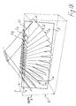
- Fig. 1 shows in a very simplified manner the operation of the principle whereon the method of the invention is based, with reference to the use of a three-dimensional scanning probe of the swinging transducer type as shown in Figures 3 to 8.
- the transducers thereof can provide scanning in a plane which contains the direction of propagation of the ultrasonic signals illuminating the object volume, i.e. the probe axis parallel to said propagation or shot direction and an axis perpendicular thereto and parallel to the transverse extension of the transducer array.
- the transducer array is swung about an axis parallel to said transverse axis (which also forms the second scanning dimension of the probe) by means of a motor and of an appropriate drive.
- the activation of the probe to transmit or receive is synchronized with the advance in such a manner as to cover the object volume V with a succession of scan planes having different predetermined orientations in space and a fanlike arrangement as illustrated and denoted as S1, S2, S3 and Sn in Fig. 1.
- Figs. 1A and 1C show the method of the invention in principle, which consists in setting, prior to scanning, the orientation and/or position parameters of the section or projection plane/s of the object volume to be displayed.
- the method provides that scanning is only performed in each scan plane along the lines which form each scan plane and coincide with or intersect the lines L1, L2, L3, Ln, i.e. the lines of the selected imaging planes intersecting each scan plane S1, S2, S3, Sn.
- the positions of these lines in space can be presumptively determined by the main processor, based on the well-known relative position of the individual scan planes and on the user-preset orientation and position parameters of the planes to be displayed.
- scanning is not performed on the whole volume, whereby imaging times are drastically reduced and image processing is considerably speeded up, and imaging is actually performed in real time, thereby allowing the operating personnel to immediately make sure that scanning took place in the conditions required therefor.
- FIG. 1A the section plane P along which imaging is to be performed is perpendicular to the array of scan planes Sn of the probe. It is apparent that, in an ideal situation, scanning shall be performed along a single line for each plane, i.e. along the line coinciding with the lines Ln of the section plane P along which imaging is to be performed, which intersect the scan planes Sn of the probe. This is clearly shown in Figure 1D in which the scan line is denoted as SCNL.
- FIG. 1B the section plane P along which imaging is to be performed is inclined with respect to the scan lines forming each scan plane Sn of the probe. Hence, for each scan plane Sn, scanning is performed along all the scan lines which are coincident or intersect the corresponding intersection line Ln between the individual scan plane Sn of the probe and the section plane P along which imaging is to be performed.
- Figure 1E in which the two extreme scan lines SCNL(1) and SCNL(1+n) are shown.
- Fig. 1C shows the most unfavorable condition, in which the section plane P along which imaging is to be performed fully cuts the scan planes Sn of the probe.
- the invention allows to focus the transmitted signals on the intersection lines Ln between the section plane P along which imaging is performed and each scan plane, thereby achieving considerable quality results.
- Figure 1F shows the scan lines SCNL(1) and SCNL(1+m) are shown.
- the signals transmitted by the probe may be focused in a differentiated along the different scan lines which form the scan planes Sn even in the case of Fig. 1B.
- the focusing rule may be differentiated along the adjacent section lines, so that for each scan line of each scan plane Sn, the transmitted beam is focused on the point intersecting the corresponding line Ln.
- the above method may also apply to probes which have a two-dimensional transducer arrangement and hence do not scan planes, but slices having a predetermined volume and comprising several adjacent scan planes together.
- the concept of a scan line may be applied to a scan band or unit volume.
- the whole scan of each scan plane Sn of the probe may be performed, while limiting scan parameters for the lines which do not intersect or coincide with the section plane P along which imaging is to be performed, or possibly even the number of lines not intersecting said section plane P, to speed up both scanning and processing and storage to the detriment of quality, but anyway obtaining an image, even though of low quality, of the regions which do not coincide with the section plane P along which imaging is to be performed.
- These image data may be combined with high quality data processed along the section plane P. This may be of help when the selected section plane P, along which imaging is to be performed, does not coincide with the actually desired one, thereby allowing to verify that the slightly different settings of the orientation parameters for the section plane P provide the actually desired image.
- This scanning method provides considerable advantages particularly when image scanning must be synchronized with transient events, specifically with the injection of contrast agents.
- contrast agents are used to display the behavior of flows, such as blood flow or else, and have specific ultrasound reflecting characteristics, to allow an optimal imaging of the flow which is naturally composed of particles having little echogenicity, or anyway a much lower echogenicity level than static tissues, which are typically hyperechogenic.
- Contrast agents naturally take well-known times to reach the object volume, e.g. an organ or part thereof, of a human body or of any other animal or vegetal living creature. Moreover, contrast agents tend to leave rapidly the region of interest and/or to a rather fast decay.
- the possibility of providing a three-dimensional complete scan of the object volume in addition to the possibility of obtaining a real time image of the conditions of the object volume while the latter is scanned allows to promptly evaluate if scanning took place when contrast agents were present, or too early with respect to the passage thereof in the object volume and to perform a new scan, if needed, in time for synchronization with the passage of contrast agents.
- the method according to the invention also allows to perform several successive scans which provide information about perfusion of the flow through the object volume.
- Imaging may be also performed on several spaced section planes P, which may be parallel and/or even transverse or intersecting each other.
- the method of the invention shall not be intended to be limited to the use in combination with the probes as shown in Figs. 4 to 8, but may also apply to any type of probe or probe system being adapted to particularly perform a three-dimensional scan.
- the spatial relation of the displaying plane to the scan planes depends on the relative position of the probe and the object volume, for example in the case of a combined use with contrast means, but without limitation thereto, it is possible to perform a first scan for setting the relative positions of the scan planes and the displaying plane, whereby position relations are defined more accurately.
- Imaging with contrast agents my be effected by performing a first scan without these agents and then, with the probe in position, by performing a continuous succession of scans while contrast agents are injected. Thanks to the possibility of always having a real time image displaying the conditions of the object volume, the operating personnel may decide to remove the unnecessary scans from the succession, for example those performed before contrast agents reach the object volume.
- the present ultrasound imaging method is particularly effective and suitable for ultrasound imaging of the liver.
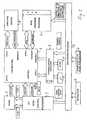
- Fig. 2 is a highly simplified block diagram of the construction of an ultrasound apparatus for implementing said method.
- the apparatus has a scan control section, including a scan control processor 1 whereto a scanning probe 2 is connected, particularly a three-dimensional scanning probe and preferably a probe as shown in Figs. 4 to 8.
- the processor controls the position of the transducers to univocally relate the received echoes with the scan plane and provides spatial position data to a four-input RAM unit, denoted as 3.
- Position parameters here being referred to cartesian coordinates but referable to any coordinate model for volume definition
- form addresses 1 univocally related to the data address 1 of the RAM unit, whereto the probe supplies, after appropriate and usual processing, the data relating to the received echo signals.
- the memory 3 becomes a three-dimensional memory in the form of a three-dimensional matrix in which the spaces of the image data memory are identified by an address corresponding or relating to the spatial location whereto image data are referred.
- scanning takes place through lines in two orthogonal directions denoted by lines x and y, whereas the third position coordinate is given by depth.
- the cartesian system is shown in Figs. 1A to 1C.
- the scan planes as shown in Figs. 1A to 1C in a fanlike arrangement are better described with reference to an angle.
- the transformation of a system into another simply consists of a transformation between reference systems and is obtained by the application of a simple transformation formula.
- the third depth dimension may be detected and obtained based on reflection time.
- the RF signal received for each scan line has a time development and the portions arriving earlier relate to smaller depths as compared with the signal portions of the same scan line which arrive progressively later.
- echo signals are appropriately sampled on a predetermined time base to obtain discrete dots.
- Discretization obtained by sampling i.e. sampling frequency affects the definition of the desired image.
- the scan control processor is controlled by a main processor 5 which is connected to means 6 for setting the imaging mode or type, e.g. B-Mode, Doppler, Power Doppler or Harmonic Imaging, and to means 7 for setting orientation and/or position parameters of the section plane or of the projection plane to be displayed.
- these means may consist of handles, selectors, keyboards, etc., not shown in detail and possibly intended to load predetermined modes or orientation and position parameters.
- the main processor 5 controls both the execution of imaging modes, thereby controlling the scan control processor 1, and a scan conversion processor, the so-called scan converter, which determines, based on the orientation and/or position parameters of the plane/s to be imaged, the lines L1, L2, L3, Ln of said planes to be imaged P intersecting the individual scan planes and identifies the memory addresses corresponding to image data along said intersecting lines, loads said data and transforms them into signals for controlling a monitor 8, by associating them to video addresses, at the inputs/outputs for addresses 3 and data 3 of the four input RAM unit 3. These data are read by the displaying monitor (data 2 and addresses 2 of the RAM unit 3) and are transformed into image lines, while the set of image lines forms the image relating to the section or projection plane to be displayed.
- a scan conversion processor the so-called scan converter
- the data pertaining to the lines L1, L2, L3, Ln of said planes to be imaged P intersecting the individual scan planes Sn are also sent to the scan control processor, for determining the scan lines to be followed for each scan plane Sn.
- the scan converter 4 is well-known and widely used in the art of ultrasound apparatuses and anyway is meant to process information with reference to a set of lines. Therefore, it might be a linear or two-dimensional scan converter.
- three-dimensional conversion i.e. a conversion through imaging planes having any orientation in space
- the object volume is achieved thanks to the combination of a linear or two-dimensional scan converter with the main processor, the scan control processor and the four input RAM unit, which allows to store and recall information collected upon scanning while constantly keeping it related to its proper position in space which is properly encoded by using data storage addresses.
- data are always univocally identifiable as regards their proper position in space and this ensures discrimination of the data pertaining to the lines of the displaying plane which intersect the scan planes for the purpose of reading them, processing them into display controls, and storing them in the form of image data in said memory, and finally recalling and displaying them on the monitor.
- a storage control processor 9 is connected to the inputs/outputs of data 4 addresses 4 of the RAM unit 3 and controls, under the supervision of the main processor 5, the storage of data onto physical storage media, such as hard disks 10, floppy disks, CD rewritable 12.
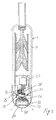
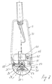
- the method of the invention is particularly effective with scanning probes of the three-dimensional motorized type, although it will be understood that the implementation of the method is not limited to the use of these probes.
- the preferred design of these probes includes, according to a first embodiment, a transducer array 20 for performing a two-dimensional scan, i.e. a scan following a plurality of lines, named lines of view, or beams, named sector beams, oriented parallel or substantially parallel to the probe axis and arranged side-by-side to cover a whole predetermined section plane of the object volume.
- a transducer array 20 for performing a two-dimensional scan, i.e. a scan following a plurality of lines, named lines of view, or beams, named sector beams, oriented parallel or substantially parallel to the probe axis and arranged side-by-side to cover a whole predetermined section plane of the object volume.
- the transducer array 20 is mounted inside a housing of a support 23 at an end of the probe.
- the support is mounted in such a manner as to swing about an axle 24 parallel to the extension of the scan planes.
- the swing axle 24 is provided at a certain distance from the transmission surface of the transducer array.
- the swinging support 23 has a toothed circular sector, i.e. a circular rack 25 on the side diametrically opposite to the axle 24, which circular rack 25 cooperates with a pinion 26.
- the pinion 26 is rotatably driven by a stepper motor 27 through a drive consisting of a gear 28 splined to the motor shaft and of a worm 29.
- the transducer array is outwardly covered by a cap 30 which is connected to the rest of the probe body, formed by a case for accommodating the connecting wires 31, the stepper motor and the drive with the pinion and the circular rack.
- the housing 32 for accommodating the transducer array, the support for the transducers and the circular rack, as well as the drive, is filled with an acoustic coupling liquid which is known and widely used in the art.
- the cap has sealing means, such as an o-ring 33, for contact with the rest of the probe body, and in the passage contained in the housing 32 for the stepper motor shaft and the connecting wires of the transducer array.
- the probe as shown in Figs. 3 and 4 is a so-called linear-sector probe.
- the transducers are arranged side-by-side along a line and are electronically activated by the control processor to generate an ultrasonic beam, whose focusing point is displaced, by appropriately activating the individual transducers arranged in a straight line, along a line parallel to the straight line wherein the transducers are arranged.
- the plane oriented in the ultrasonic beam transmission direction and parallel to the line wherein the adjacent transducers are arranged is scanned.
- each scan plane consists of a set of lines of view along which the transmitted ultrasonic beam is focused at a certain depth or distance from the surface of the transducers, the focusing rule remaining the same for each line of view.
- the swing axle is set back from the transmission plane of the transducers 20, which allows to maintain a substantially identical distance between the transducers and the facing wall of the covering cap 30.
- the probe as shown in Figures 5 and 6 has a construction which is substantially similar to the above described probe of Figures 3 and 4.
- the transducer is a phased-array transducer, differing in that the focusing rule varies according to the line of view.
- the transducer array 20 may be linear, as described above, or two-dimensional, i.e. having transducers arranged in two directions, i.e. over a surface. In this case, a section slice of the object volume may be scanned instead of a section plane.
- This does not change the operation of the apparatus and the steps of the method according to the present invention which, though being described with specific reference to probes having a linear transducer array, may also apply to probes with two-dimensional transducers, by simply modifying the scanning and processing control rule, based on the fact that information to be obtained has to relate not only to several scan planes but to several scanning slices, or three-dimensional scanning sections.
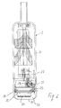
- the probe as shown in Figures 7 and 8 is an additional embodiment of the above described probes.
- the transducer array 20 swings about the axis of a first axle parallel to the extension of the adjacently arranged transducers by means of the same mechanism as previously described with reference to the probes of Figs. 3 to 6.
- the transducer is mounted in such a manner as to additionally swing about the axis of another axle 40, perpendicular to the first swing axle and parallel to the plane containing said first swing axle.
- This arrangement allows to scan a section plane by swinging the transducer array about the axis of the second swing axle and this allows to use annular or mono transducers.
- the transducer array may also have a two-dimensional transducer arrangement, i.e. disposed over a surface, as described above for the probes of Figs. 3 to 6.
- the transducer array 20, the support 23 swinging about the axis of first axle 24 parallel to the extension of the scan planes, the supports of said swing axle 24, the toothed circular sector 25 integral with the transducer array support 23, the pinion 26 cooperating therewith, as well as the first stepper motor 27, are mounted on a support stirrup 41 which is supported so as to oscillate about the axis of the axle 40.
- the stirrup 41 is integral, on the side diametrically opposite to the axle 40, and like the mechanism allowing oscillation about the axle 24, with a circular rack 42 which is engaged with a driving pinion 45, rotatably driven by a second motor 44.
- the two motors 27 and 44 cooperate directly with the circular rack 25, 42, with no drive intervening therebetween.
- the scan control processor has to control two motors 27 and 44 in a synchronized manner.
- this embodiment provides an increased flexibility in handling imaging modes, as it allows to handle the combinations of swinging steps in the two directions in a simple and specific manner, so as to define arrays of scan planes whose orientations may differ from those imposed by linear probes, or by probes with a two-dimensional transducer arrangement only swinging about one axis.
- the probe according to this embodiment may be easily used, by an appropriate focusing rule, variable with the inclinations of the two axles 24 and 40, to perform targeted scans of a few lines of view only, without having to scan whole volumes.
- the two above probes might as well perform a similar targeted and selective scan, but, besides the electronic control for management of the focusing rule, the rule for sweeping the lines of view which form the scan plane should also be changed electronically, whereas, in the probe of Figs. 7 and 8, the control is limited to the simple physical oscillation of the transducer array.
- the probe of Figs. 7 and 8 allows to scan individual unit volumes of the object volume.
- An advantage of the probes according to the three different described embodiments, when combined with a transducer array having a side-by-side arrangement in two spatial directions, i.e. over a surface, is that it allows to obtain so-called three-dimensional transducer arrays, which can perform a three-dimensional scan only electronically, by varying the transducer activation rule, and/or by varying the focusing rule, ensuring, with a limited number and extension of transducers, the whole object volume is covered.
- the oscillation of the transducer array ensures that the probe is swept to scan the whole object volume, which would require very large two-dimensional transducer arrays.
- transducers may be still provided in small numbers, and the small scanning extension in the direction of the size of the two-dimensional transducer array is obviated by the oscillation of the transducer array in said direction.
- the arrangement to provide small numbers of transducers in the probe is important, since each transducer must be connected by a dedicated wire.
- the double mechanical oscillation probe as shown in Figs. 7 and 8.
- the transducers arranged in two directions may be provided in very small numbers, with reference to the extension of the transducer array in both directions.
- the oscillation in the two transverse, particularly perpendicular directions allows to obviate the restriction of the probe effectiveness range.
- the arrangement of this embodiment also provides a probe, whose transducers are arranged on a plane, i.e. in two dimensions, which has a very small size, at least as regards the probe head.
- This type of probe is well adapted to the use for imaging volumes or organs whose windows of view have very small sizes, such as for intercostal imaging, or the like.
- the invention is not limited to what is described and illustrated herein, but may be greatly varied especially as regards construction without departure from the inventive principle disclosed above and claimed below.
- the invention may be used in combination of any kind of imaging mode or method known in the art, with or without the use of contrast agents or the like.
Applications Claiming Priority (2)
| Application Number | Priority Date | Filing Date | Title |
|---|---|---|---|
| ITSV000027 | 2000-06-22 | ||
| IT2000SV000027A ITSV20000027A1 (it) | 2000-06-22 | 2000-06-22 | Metodo e macchina per l'acquisizione di immagini ecografiche in particolare di tipo tridimensionale nonche' sonda di acquisizione |
Publications (2)
| Publication Number | Publication Date |
|---|---|
| EP1167996A1 true EP1167996A1 (de) | 2002-01-02 |
| EP1167996B1 EP1167996B1 (de) | 2012-11-07 |
Family
ID=11457041
Family Applications (1)
| Application Number | Title | Priority Date | Filing Date |
|---|---|---|---|
| EP01113159A Expired - Lifetime EP1167996B1 (de) | 2000-06-22 | 2001-05-30 | Ultraschallabbildungsverfahren und Vorrichtung, insbesondere für dreidimensionale Abbildung |
Country Status (3)
| Country | Link |
|---|---|
| US (1) | US6572548B2 (de) |
| EP (1) | EP1167996B1 (de) |
| IT (1) | ITSV20000027A1 (de) |
Cited By (8)
| Publication number | Priority date | Publication date | Assignee | Title |
|---|---|---|---|---|
| WO2004021039A1 (en) * | 2002-08-29 | 2004-03-11 | Koninklijke Philips Electronics N.V. | Ultrasonic diagnostic imaging system with elevation biplane images |
| EP1609421A1 (de) * | 2004-06-22 | 2005-12-28 | General Electric Company | Verfahren und Vorrichtung zum Definieren eines Protokolls für ein Ultraschallgerät |
| US7037264B2 (en) | 2000-08-17 | 2006-05-02 | Koninklijke Philips Electronics N.V. | Ultrasonic diagnostic imaging with steered image plane |
| EP2147636A1 (de) | 2008-07-24 | 2010-01-27 | Esaote S.p.A. | Vorrichtung und Verfahren zum Führen von chirurgischen Werkzeugen durch Ultraschallbildgebung |
| US8480583B2 (en) | 2007-10-16 | 2013-07-09 | General Electric Company | Methods and apparatus for 4D data acquisition and analysis in an ultrasound protocol examination |
| EP3400878A1 (de) | 2017-05-10 | 2018-11-14 | Esaote S.p.A. | Verfahren zur stellungsunabhängigen lokalisierung von zielen in diagnostischen bildern, die durch multimodale erfassungen erworben werden, und system zur durchführung des verfahrens |
| EP3524160A1 (de) | 2018-02-07 | 2019-08-14 | Esaote S.p.A. | Ultraschallsonde und mit der besagten ultraschallsonde ausgestattetes ultraschallsystem |
| US20190269390A1 (en) * | 2011-08-21 | 2019-09-05 | Transenterix Europe S.A.R.L. | Device and method for assisting laparoscopic surgery - rule based approach |
Families Citing this family (42)
| Publication number | Priority date | Publication date | Assignee | Title |
|---|---|---|---|---|
| US20030069569A1 (en) * | 2001-08-29 | 2003-04-10 | Burdette Everette C. | Ultrasound device for treatment of intervertebral disc tissue |
| US20030055338A1 (en) * | 2001-09-18 | 2003-03-20 | Josef Steininger | Apparatus and methods for ultrasound imaging with positioning of the transducer array |
| JP2004000499A (ja) * | 2002-03-27 | 2004-01-08 | Aloka Co Ltd | 超音波医療システム |
| JP2004141514A (ja) * | 2002-10-28 | 2004-05-20 | Toshiba Corp | 画像処理装置及び超音波診断装置 |
| AU2003278424A1 (en) * | 2002-11-06 | 2004-06-07 | Koninklijke Philips Electronics N.V. | Phased array acoustic system for 3d imaging of moving parts_____ |
| US20040254466A1 (en) * | 2003-06-16 | 2004-12-16 | James Boner | Apparatus and method for real time three-dimensional ultrasound imaging |
| US7457672B2 (en) * | 2003-09-10 | 2008-11-25 | General Electric Company | Method and apparatus for exporting ultrasound data |
| EP1517142A1 (de) * | 2003-09-16 | 2005-03-23 | Nederlandse Organisatie voor toegepast-natuurwetenschappelijk Onderzoek TNO | Vorrichtung und Verfahren zur Untersuchung von Laminat-Schichtstoffen |
| US20050113690A1 (en) * | 2003-11-25 | 2005-05-26 | Nahi Halmann | Methods and systems for providing portable device extended resources |
| US7081093B2 (en) * | 2003-12-05 | 2006-07-25 | Vermon | Array transducer for 3D tilting probes |
| US20050234340A1 (en) * | 2004-03-31 | 2005-10-20 | Brock-Fisher George A | Bolus control for contrast imaging with 3D |
| CN101035471B (zh) * | 2004-10-08 | 2012-02-08 | 皇家飞利浦电子股份有限公司 | 三维诊断超声图像显示 |
| EP1681020B1 (de) * | 2005-01-18 | 2008-06-04 | Esaote S.p.A. | Verfahren zur Ultraschallabbildung und Sonde zur 3D gynäkologischen Untersuchung |
| US20070041613A1 (en) * | 2005-05-11 | 2007-02-22 | Luc Perron | Database of target objects suitable for use in screening receptacles or people and method and apparatus for generating same |
| US7991242B2 (en) | 2005-05-11 | 2011-08-02 | Optosecurity Inc. | Apparatus, method and system for screening receptacles and persons, having image distortion correction functionality |
| CA2608119A1 (en) * | 2005-05-11 | 2006-11-16 | Optosecurity Inc. | Method and system for screening luggage items, cargo containers or persons |
| KR100748585B1 (ko) * | 2005-07-15 | 2007-08-13 | 주식회사 메디슨 | 부가정보를 이용하여 영상을 구성하는 초음파 시스템 |
| US20070062290A1 (en) * | 2005-08-30 | 2007-03-22 | Ultrasonic Technologies Ltd. | Motor driven mechanism for mechanically scanned ultrasound transducers |
| US20080004527A1 (en) * | 2006-04-05 | 2008-01-03 | Coleman D Jackson | High-resolution ultrasound spectral and wavelet analysis of vascular tissue |
| CA2584683A1 (en) * | 2006-04-20 | 2007-10-20 | Optosecurity Inc. | Apparatus, method and system for screening receptacles and persons |
| US7899232B2 (en) * | 2006-05-11 | 2011-03-01 | Optosecurity Inc. | Method and apparatus for providing threat image projection (TIP) in a luggage screening system, and luggage screening system implementing same |
| US8494210B2 (en) * | 2007-03-30 | 2013-07-23 | Optosecurity Inc. | User interface for use in security screening providing image enhancement capabilities and apparatus for implementing same |
| EP1944070A1 (de) * | 2007-01-12 | 2008-07-16 | Esaote S.p.A. | Bidimensionales Ultraschall-Array zur volumetrischen Bildgebung |
| US10183183B2 (en) | 2007-04-13 | 2019-01-22 | Acoustic Medsystems, Inc. | Acoustic applicators for controlled thermal modification of tissue |
| WO2010097729A1 (en) | 2009-02-27 | 2010-09-02 | Koninklijke Philips Electronics, N.V. | Pre-collapsed cmut with mechanical collapse retention |
| EP2309929B1 (de) * | 2008-08-01 | 2019-05-15 | Koninklijke Philips N.V. | Ultraschallsonde für dreidimensionale bildgebung |
| JP2010207428A (ja) * | 2009-03-11 | 2010-09-24 | Toshiba Corp | 超音波プローブ |
| JP2012527324A (ja) * | 2009-05-19 | 2012-11-08 | エンドラ,インコーポレイテッド | 組織を分析するための熱音響システム |
| US8159680B2 (en) * | 2010-02-16 | 2012-04-17 | Massachusetts Institute Of Technology | Single-transducer, three-dimensional laser imaging system and method |
| FR2965923B1 (fr) * | 2010-10-11 | 2012-12-14 | Commissariat Energie Atomique | Dispositif de sondage a ultrasons, procede de commande de transducteurs d'une sonde a ultrasons et programme d'ordinateur correspondant |
| WO2012076918A1 (en) | 2010-12-10 | 2012-06-14 | B-K Medical Aps | Imaging transducer probe |
| US20120245466A1 (en) * | 2011-03-25 | 2012-09-27 | Infosys Technologies, Ltd. | Method and system for capturing medical imaging data |
| CA2849398C (en) | 2011-09-07 | 2020-12-29 | Rapiscan Systems, Inc. | X-ray inspection system that integrates manifest data with imaging/detection processing |
| JP2013081764A (ja) * | 2011-09-27 | 2013-05-09 | Toshiba Corp | 超音波診断装置及び超音波走査プログラム |
| KR101387934B1 (ko) * | 2011-12-08 | 2014-04-23 | 삼성메디슨 주식회사 | 초음파 진단장치 |
| WO2013170053A1 (en) | 2012-05-09 | 2013-11-14 | The Regents Of The University Of Michigan | Linear magnetic drive transducer for ultrasound imaging |
| US20150209551A1 (en) | 2012-08-15 | 2015-07-30 | Everette C. Burdette | Mri compatible ablation catheter system incorporating directional high-intensity ultrasound for treatment |
| WO2016118947A1 (en) | 2015-01-23 | 2016-07-28 | The University Of North Carolina At Chapel Hill | Apparatuses, systems, and methods for preclinical ultrasound imaging of subjects |
| WO2017146930A1 (en) | 2016-02-22 | 2017-08-31 | Rapiscan Systems, Inc. | Systems and methods for detecting threats and contraband in cargo |
| CN107802287B (zh) * | 2017-11-16 | 2020-05-19 | 深圳纯和医药有限公司 | 提高超声诊断仪4d机械探头成像稳定度的方法 |
| CN110505465B (zh) * | 2019-08-30 | 2022-08-23 | 京东方科技集团股份有限公司 | 数据传输方法、三维图像显示方法、装置及电子设备 |
| CN113552573B (zh) * | 2021-06-29 | 2022-07-29 | 复旦大学 | 一种基于超声环阵合成孔径接收的快速成像算法 |
Citations (12)
| Publication number | Priority date | Publication date | Assignee | Title |
|---|---|---|---|---|
| FR2651990A1 (fr) * | 1989-09-15 | 1991-03-22 | Philips Electronique Lab | Sonde pour echographie en trois dimensions. |
| US5159931A (en) * | 1988-11-25 | 1992-11-03 | Riccardo Pini | Apparatus for obtaining a three-dimensional reconstruction of anatomic structures through the acquisition of echographic images |
| US5226113A (en) * | 1989-10-30 | 1993-07-06 | General Electric Company | Method and apparatus for volumetric projection rendering using reverse ray casting |
| US5396890A (en) * | 1993-09-30 | 1995-03-14 | Siemens Medical Systems, Inc. | Three-dimensional scan converter for ultrasound imaging |
| US5497776A (en) * | 1993-08-05 | 1996-03-12 | Olympus Optical Co., Ltd. | Ultrasonic image diagnosing apparatus for displaying three-dimensional image |
| US5740804A (en) * | 1996-10-18 | 1998-04-21 | Esaote, S.P.A | Multipanoramic ultrasonic probe |
| WO1998043109A1 (en) * | 1997-03-21 | 1998-10-01 | Life Imaging Systems Inc. | Three-dimensional imaging system |
| US5899861A (en) * | 1995-03-31 | 1999-05-04 | Siemens Medical Systems, Inc. | 3-dimensional volume by aggregating ultrasound fields of view |
| US5928151A (en) * | 1997-08-22 | 1999-07-27 | Acuson Corporation | Ultrasonic system and method for harmonic imaging in three dimensions |
| EP0952463A2 (de) * | 1998-04-23 | 1999-10-27 | General Electric Company | Verfahren und Vorrichtung für dreidimensionale Ultraschall-Abbildung mit Kontrastmitteln und harmonischen Echos |
| US6036646A (en) * | 1998-07-10 | 2000-03-14 | Guided Therapy Systems, Inc. | Method and apparatus for three dimensional ultrasound imaging |
| US6059728A (en) * | 1997-01-02 | 2000-05-09 | Storz Instrument Co. | Three-dimensional ultrasound imaging system and probe |
Family Cites Families (5)
| Publication number | Priority date | Publication date | Assignee | Title |
|---|---|---|---|---|
| US5070879A (en) * | 1989-11-30 | 1991-12-10 | Acoustic Imaging Technologies Corp. | Ultrasound imaging method and apparatus |
| AU674518B2 (en) | 1992-07-20 | 1997-01-02 | Presstek, Inc. | Lithographic printing plates for use with laser-discharge imaging apparatus |
| JPH0663040A (ja) * | 1992-08-19 | 1994-03-08 | Fuji Electric Co Ltd | 超音波診断装置 |
| JPH10277030A (ja) * | 1997-04-09 | 1998-10-20 | Aloka Co Ltd | 超音波診断装置 |
| US6276211B1 (en) | 1999-02-09 | 2001-08-21 | Duke University | Methods and systems for selective processing of transmit ultrasound beams to display views of selected slices of a volume |
-
2000
- 2000-06-22 IT IT2000SV000027A patent/ITSV20000027A1/it unknown
-
2001
- 2001-05-30 EP EP01113159A patent/EP1167996B1/de not_active Expired - Lifetime
- 2001-06-15 US US09/882,598 patent/US6572548B2/en not_active Expired - Lifetime
Patent Citations (12)
| Publication number | Priority date | Publication date | Assignee | Title |
|---|---|---|---|---|
| US5159931A (en) * | 1988-11-25 | 1992-11-03 | Riccardo Pini | Apparatus for obtaining a three-dimensional reconstruction of anatomic structures through the acquisition of echographic images |
| FR2651990A1 (fr) * | 1989-09-15 | 1991-03-22 | Philips Electronique Lab | Sonde pour echographie en trois dimensions. |
| US5226113A (en) * | 1989-10-30 | 1993-07-06 | General Electric Company | Method and apparatus for volumetric projection rendering using reverse ray casting |
| US5497776A (en) * | 1993-08-05 | 1996-03-12 | Olympus Optical Co., Ltd. | Ultrasonic image diagnosing apparatus for displaying three-dimensional image |
| US5396890A (en) * | 1993-09-30 | 1995-03-14 | Siemens Medical Systems, Inc. | Three-dimensional scan converter for ultrasound imaging |
| US5899861A (en) * | 1995-03-31 | 1999-05-04 | Siemens Medical Systems, Inc. | 3-dimensional volume by aggregating ultrasound fields of view |
| US5740804A (en) * | 1996-10-18 | 1998-04-21 | Esaote, S.P.A | Multipanoramic ultrasonic probe |
| US6059728A (en) * | 1997-01-02 | 2000-05-09 | Storz Instrument Co. | Three-dimensional ultrasound imaging system and probe |
| WO1998043109A1 (en) * | 1997-03-21 | 1998-10-01 | Life Imaging Systems Inc. | Three-dimensional imaging system |
| US5928151A (en) * | 1997-08-22 | 1999-07-27 | Acuson Corporation | Ultrasonic system and method for harmonic imaging in three dimensions |
| EP0952463A2 (de) * | 1998-04-23 | 1999-10-27 | General Electric Company | Verfahren und Vorrichtung für dreidimensionale Ultraschall-Abbildung mit Kontrastmitteln und harmonischen Echos |
| US6036646A (en) * | 1998-07-10 | 2000-03-14 | Guided Therapy Systems, Inc. | Method and apparatus for three dimensional ultrasound imaging |
Cited By (10)
| Publication number | Priority date | Publication date | Assignee | Title |
|---|---|---|---|---|
| US7037264B2 (en) | 2000-08-17 | 2006-05-02 | Koninklijke Philips Electronics N.V. | Ultrasonic diagnostic imaging with steered image plane |
| WO2004021039A1 (en) * | 2002-08-29 | 2004-03-11 | Koninklijke Philips Electronics N.V. | Ultrasonic diagnostic imaging system with elevation biplane images |
| EP1609421A1 (de) * | 2004-06-22 | 2005-12-28 | General Electric Company | Verfahren und Vorrichtung zum Definieren eines Protokolls für ein Ultraschallgerät |
| US8480583B2 (en) | 2007-10-16 | 2013-07-09 | General Electric Company | Methods and apparatus for 4D data acquisition and analysis in an ultrasound protocol examination |
| EP2147636A1 (de) | 2008-07-24 | 2010-01-27 | Esaote S.p.A. | Vorrichtung und Verfahren zum Führen von chirurgischen Werkzeugen durch Ultraschallbildgebung |
| US10492758B2 (en) | 2008-07-24 | 2019-12-03 | Esaote, S.P.A. | Device and method for guiding surgical tools |
| US20190269390A1 (en) * | 2011-08-21 | 2019-09-05 | Transenterix Europe S.A.R.L. | Device and method for assisting laparoscopic surgery - rule based approach |
| EP3400878A1 (de) | 2017-05-10 | 2018-11-14 | Esaote S.p.A. | Verfahren zur stellungsunabhängigen lokalisierung von zielen in diagnostischen bildern, die durch multimodale erfassungen erworben werden, und system zur durchführung des verfahrens |
| EP3524160A1 (de) | 2018-02-07 | 2019-08-14 | Esaote S.p.A. | Ultraschallsonde und mit der besagten ultraschallsonde ausgestattetes ultraschallsystem |
| US11547387B2 (en) | 2018-02-07 | 2023-01-10 | Esaote S.P.A. | Ultrasound probe and ultrasound system provided with said ultrasound probe |
Also Published As
| Publication number | Publication date |
|---|---|
| EP1167996B1 (de) | 2012-11-07 |
| US20020016546A1 (en) | 2002-02-07 |
| ITSV20000027A1 (it) | 2001-12-22 |
| ITSV20000027A0 (it) | 2000-06-22 |
| US6572548B2 (en) | 2003-06-03 |
Similar Documents
| Publication | Publication Date | Title |
|---|---|---|
| EP1167996B1 (de) | Ultraschallabbildungsverfahren und Vorrichtung, insbesondere für dreidimensionale Abbildung | |
| US5840032A (en) | Method and apparatus for three-dimensional ultrasound imaging using transducer array having uniform elevation beamwidth | |
| US4509368A (en) | Ultrasound tomography | |
| Kisslo et al. | Real‐time volumetric echocardiography: the technology and the possibilities | |
| US6443896B1 (en) | Method for creating multiplanar ultrasonic images of a three dimensional object | |
| US5865750A (en) | Method and apparatus for enhancing segmentation in three-dimensional ultrasound imaging | |
| EP1543345B1 (de) | Ultraschalldiagnoseabbildungssystem mit höhen-biebenenbildern | |
| US4455872A (en) | Rotating ultrasonic scanner | |
| JP3878343B2 (ja) | 3次元超音波診断装置 | |
| US6186948B1 (en) | Ultrasonic diagnostic apparatus | |
| US6669641B2 (en) | Method of and system for ultrasound imaging | |
| US20050113689A1 (en) | Method and apparatus for performing multi-mode imaging | |
| JP2000152939A (ja) | 物体ボリュ―ムの3次元イメ―ジングのためのシステム及び方法 | |
| CN105491959A (zh) | 弹性成像测量系统和方法 | |
| US6503199B1 (en) | Uniform volumetric scanning ultrasonic diagnostic imaging system | |
| JP2007513672A (ja) | 2次元アレイトランスデューサを用いる立体的超音波画像化システム | |
| JP4138480B2 (ja) | 超音波診断装置 | |
| Hottier et al. | 3D echography: status and perspective | |
| JP4800214B2 (ja) | カラーフローバイプレーンの超音波撮像システム及び方法 | |
| JP3750972B2 (ja) | 3次元超音波診断装置 | |
| US6059728A (en) | Three-dimensional ultrasound imaging system and probe | |
| Kossoff et al. | Octoson—A new rapid general purpose echoscope | |
| US6547735B1 (en) | Partial rayline volumetric scanning ultrasonic diagnostic imaging system | |
| Pavy Jr | Real-time ultrasonic volumetric imaging with stereoscopic display | |
| JPS61128948A (ja) | 超音波映像装置 |
Legal Events
| Date | Code | Title | Description |
|---|---|---|---|
| PUAI | Public reference made under article 153(3) epc to a published international application that has entered the european phase |
Free format text: ORIGINAL CODE: 0009012 |
|
| AK | Designated contracting states |
Kind code of ref document: A1 Designated state(s): AT BE CH CY DE DK ES FI FR GB GR IE IT LI LU MC NL PT SE TR |
|
| AX | Request for extension of the european patent |
Free format text: AL;LT;LV;MK;RO;SI |
|
| 17P | Request for examination filed |
Effective date: 20011221 |
|
| AKX | Designation fees paid |
Free format text: AT BE CH CY DE DK ES FI FR GB GR IE IT LI LU MC NL PT SE TR |
|
| RAP1 | Party data changed (applicant data changed or rights of an application transferred) |
Owner name: ESAOTE S.P.A. |
|
| RAP1 | Party data changed (applicant data changed or rights of an application transferred) |
Owner name: ESAOTE S.P.A. |
|
| RAP1 | Party data changed (applicant data changed or rights of an application transferred) |
Owner name: ESAOTE S.P.A. |
|
| 17Q | First examination report despatched |
Effective date: 20090218 |
|
| GRAP | Despatch of communication of intention to grant a patent |
Free format text: ORIGINAL CODE: EPIDOSNIGR1 |
|
| GRAS | Grant fee paid |
Free format text: ORIGINAL CODE: EPIDOSNIGR3 |
|
| GRAA | (expected) grant |
Free format text: ORIGINAL CODE: 0009210 |
|
| AK | Designated contracting states |
Kind code of ref document: B1 Designated state(s): AT BE CH CY DE DK ES FI FR GB GR IE IT LI LU MC NL PT SE TR |
|
| REG | Reference to a national code |
Ref country code: GB Ref legal event code: FG4D |
|
| REG | Reference to a national code |
Ref country code: AT Ref legal event code: REF Ref document number: 583218 Country of ref document: AT Kind code of ref document: T Effective date: 20121115 Ref country code: CH Ref legal event code: EP |
|
| REG | Reference to a national code |
Ref country code: IE Ref legal event code: FG4D |
|
| REG | Reference to a national code |
Ref country code: DE Ref legal event code: R096 Ref document number: 60147321 Country of ref document: DE Effective date: 20130103 |
|
| REG | Reference to a national code |
Ref country code: AT Ref legal event code: MK05 Ref document number: 583218 Country of ref document: AT Kind code of ref document: T Effective date: 20121107 |
|
| REG | Reference to a national code |
Ref country code: NL Ref legal event code: VDEP Effective date: 20121107 |
|
| PG25 | Lapsed in a contracting state [announced via postgrant information from national office to epo] |
Ref country code: FI Free format text: LAPSE BECAUSE OF FAILURE TO SUBMIT A TRANSLATION OF THE DESCRIPTION OR TO PAY THE FEE WITHIN THE PRESCRIBED TIME-LIMIT Effective date: 20121107 Ref country code: ES Free format text: LAPSE BECAUSE OF FAILURE TO SUBMIT A TRANSLATION OF THE DESCRIPTION OR TO PAY THE FEE WITHIN THE PRESCRIBED TIME-LIMIT Effective date: 20130218 Ref country code: SE Free format text: LAPSE BECAUSE OF FAILURE TO SUBMIT A TRANSLATION OF THE DESCRIPTION OR TO PAY THE FEE WITHIN THE PRESCRIBED TIME-LIMIT Effective date: 20121107 Ref country code: NL Free format text: LAPSE BECAUSE OF FAILURE TO SUBMIT A TRANSLATION OF THE DESCRIPTION OR TO PAY THE FEE WITHIN THE PRESCRIBED TIME-LIMIT Effective date: 20121107 |
|
| PG25 | Lapsed in a contracting state [announced via postgrant information from national office to epo] |
Ref country code: CY Free format text: LAPSE BECAUSE OF FAILURE TO SUBMIT A TRANSLATION OF THE DESCRIPTION OR TO PAY THE FEE WITHIN THE PRESCRIBED TIME-LIMIT Effective date: 20121107 Ref country code: BE Free format text: LAPSE BECAUSE OF FAILURE TO SUBMIT A TRANSLATION OF THE DESCRIPTION OR TO PAY THE FEE WITHIN THE PRESCRIBED TIME-LIMIT Effective date: 20121107 Ref country code: PT Free format text: LAPSE BECAUSE OF FAILURE TO SUBMIT A TRANSLATION OF THE DESCRIPTION OR TO PAY THE FEE WITHIN THE PRESCRIBED TIME-LIMIT Effective date: 20130307 Ref country code: GR Free format text: LAPSE BECAUSE OF FAILURE TO SUBMIT A TRANSLATION OF THE DESCRIPTION OR TO PAY THE FEE WITHIN THE PRESCRIBED TIME-LIMIT Effective date: 20130208 |
|
| PG25 | Lapsed in a contracting state [announced via postgrant information from national office to epo] |
Ref country code: AT Free format text: LAPSE BECAUSE OF FAILURE TO SUBMIT A TRANSLATION OF THE DESCRIPTION OR TO PAY THE FEE WITHIN THE PRESCRIBED TIME-LIMIT Effective date: 20121107 |
|
| PG25 | Lapsed in a contracting state [announced via postgrant information from national office to epo] |
Ref country code: DK Free format text: LAPSE BECAUSE OF FAILURE TO SUBMIT A TRANSLATION OF THE DESCRIPTION OR TO PAY THE FEE WITHIN THE PRESCRIBED TIME-LIMIT Effective date: 20121107 |
|
| PLBE | No opposition filed within time limit |
Free format text: ORIGINAL CODE: 0009261 |
|
| STAA | Information on the status of an ep patent application or granted ep patent |
Free format text: STATUS: NO OPPOSITION FILED WITHIN TIME LIMIT |
|
| 26N | No opposition filed |
Effective date: 20130808 |
|
| REG | Reference to a national code |
Ref country code: DE Ref legal event code: R097 Ref document number: 60147321 Country of ref document: DE Effective date: 20130808 |
|
| PG25 | Lapsed in a contracting state [announced via postgrant information from national office to epo] |
Ref country code: MC Free format text: LAPSE BECAUSE OF FAILURE TO SUBMIT A TRANSLATION OF THE DESCRIPTION OR TO PAY THE FEE WITHIN THE PRESCRIBED TIME-LIMIT Effective date: 20121107 |
|
| REG | Reference to a national code |
Ref country code: CH Ref legal event code: PL |
|
| PG25 | Lapsed in a contracting state [announced via postgrant information from national office to epo] |
Ref country code: CH Free format text: LAPSE BECAUSE OF NON-PAYMENT OF DUE FEES Effective date: 20130531 Ref country code: LI Free format text: LAPSE BECAUSE OF NON-PAYMENT OF DUE FEES Effective date: 20130531 |
|
| REG | Reference to a national code |
Ref country code: IE Ref legal event code: MM4A |
|
| PG25 | Lapsed in a contracting state [announced via postgrant information from national office to epo] |
Ref country code: IE Free format text: LAPSE BECAUSE OF NON-PAYMENT OF DUE FEES Effective date: 20130530 |
|
| PG25 | Lapsed in a contracting state [announced via postgrant information from national office to epo] |
Ref country code: TR Free format text: LAPSE BECAUSE OF FAILURE TO SUBMIT A TRANSLATION OF THE DESCRIPTION OR TO PAY THE FEE WITHIN THE PRESCRIBED TIME-LIMIT Effective date: 20121107 |
|
| PG25 | Lapsed in a contracting state [announced via postgrant information from national office to epo] |
Ref country code: LU Free format text: LAPSE BECAUSE OF NON-PAYMENT OF DUE FEES Effective date: 20130530 |
|
| REG | Reference to a national code |
Ref country code: FR Ref legal event code: PLFP Year of fee payment: 16 |
|
| REG | Reference to a national code |
Ref country code: FR Ref legal event code: PLFP Year of fee payment: 17 |
|
| REG | Reference to a national code |
Ref country code: FR Ref legal event code: PLFP Year of fee payment: 18 |
|
| PGFP | Annual fee paid to national office [announced via postgrant information from national office to epo] |
Ref country code: DE Payment date: 20200519 Year of fee payment: 20 Ref country code: FR Payment date: 20200518 Year of fee payment: 20 |
|
| PGFP | Annual fee paid to national office [announced via postgrant information from national office to epo] |
Ref country code: IT Payment date: 20200514 Year of fee payment: 20 Ref country code: GB Payment date: 20200515 Year of fee payment: 20 |
|
| REG | Reference to a national code |
Ref country code: DE Ref legal event code: R071 Ref document number: 60147321 Country of ref document: DE |
|
| REG | Reference to a national code |
Ref country code: GB Ref legal event code: PE20 Expiry date: 20210529 |
|
| PG25 | Lapsed in a contracting state [announced via postgrant information from national office to epo] |
Ref country code: GB Free format text: LAPSE BECAUSE OF EXPIRATION OF PROTECTION Effective date: 20210529 |