EP1167947A2 - Methods and apparatus for measuring suspended-substance concentrations - Google Patents
Methods and apparatus for measuring suspended-substance concentrations Download PDFInfo
- Publication number
- EP1167947A2 EP1167947A2 EP01109072A EP01109072A EP1167947A2 EP 1167947 A2 EP1167947 A2 EP 1167947A2 EP 01109072 A EP01109072 A EP 01109072A EP 01109072 A EP01109072 A EP 01109072A EP 1167947 A2 EP1167947 A2 EP 1167947A2
- Authority
- EP
- European Patent Office
- Prior art keywords
- pressure side
- low
- straightner
- pressure
- liquid
- Prior art date
- Legal status (The legal status is an assumption and is not a legal conclusion. Google has not performed a legal analysis and makes no representation as to the accuracy of the status listed.)
- Withdrawn
Links
Images




Classifications
-
- G—PHYSICS
- G01—MEASURING; TESTING
- G01N—INVESTIGATING OR ANALYSING MATERIALS BY DETERMINING THEIR CHEMICAL OR PHYSICAL PROPERTIES
- G01N9/00—Investigating density or specific gravity of materials; Analysing materials by determining density or specific gravity
- G01N9/26—Investigating density or specific gravity of materials; Analysing materials by determining density or specific gravity by measuring pressure differences
-
- G—PHYSICS
- G01—MEASURING; TESTING
- G01N—INVESTIGATING OR ANALYSING MATERIALS BY DETERMINING THEIR CHEMICAL OR PHYSICAL PROPERTIES
- G01N9/00—Investigating density or specific gravity of materials; Analysing materials by determining density or specific gravity
- G01N9/36—Analysing materials by measuring the density or specific gravity, e.g. determining quantity of moisture
Definitions
- the present invention relates to methods and apparatus for measuring suspended-substance concentrations by measuring the pressure difference between two points distantly located in the depth direction of a stream flow and thereby determining the average density of the stream flow between the two points, whereby a suspended-substance concentration between the two points is measured.
- the present invention has been made to solve the above-mentioned problems.
- the pressure difference between two points distantly located in the depth direction of a stream flow is detected with a differential pressure transmitter, the average density of the stream flow between the two points is calculated from the pressure difference, and the difference between the average density and the reference density of the stream flow is used as an index for measuring suspended-substance concentrations.
- the present invention enables the provision of methods and apparatus for measuring suspended-substance concentrations that allow for real-time, continuous measurement and easy maintenance and control, and offer high measurement accuracy and wide measuring ranges.
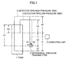
- FIG. 1 is a schematic view explaining a method for measuring suspended-substance concentrations according to the present invention.
- the numeral 1 indicates a tank corresponding to a dam or river wherein suspended-substance concentrations are measured and the tank is filled with water.
- the numeral 2 indicates a differential pressure transmitter provided with a diaphragm (not shown in the figure) which, once given inputs of high and low pressures, detects the difference between the pressures.
- the differential pressure transmitter converts the detected pressure difference to an electric signal and outputs the signal.
- Connected to the input stage of the differential pressure transmitter (2) are a detector pipe (low pressure side) (3) and a detector pipe (high pressure side) (4) inserted to given depths of the tank.
- the tip of the detector pipe (high pressure side) (4) is inserted into the tank (1) deeper than that of the detector pipe (low pressure side) (3) by as much as a distance H.
- the interiors of the detector pipe (low pressure side) (3) and detector pipe (high pressure side) (4) are either water-sealed or water-purged.
- the numeral 5 indicates a computing unit connected to the differential pressure transmitter (2) and is given the input of an output signal provided by the differential pressure transmitter (2).
- a high pressure P1 and a low pressure P2 applied to the differential pressure transmitter (2) are respectively represented by equations 1 and 2 given below:
- P1 ⁇ H1 - ⁇ 0(H1 + h1) + ⁇ 0(h1 + H1 + H - h4) + P0
- P2 ⁇ H2 - ⁇ 0(H2 + h2) + ⁇ 0(h2 + H1 + H - h3) + P0
- the differential pressure transmitter (2) detects the pressure difference (P1 - P2) given by equation 3 below by means of the diaphragm, according to equations 1 and 2. The differential pressure transmitter (2) then converts the pressure difference to an electric signal.
- P1 - P2 H ( ⁇ - ⁇ 0)
- the computing unit (5) calculates the average density ⁇ , given an output signal (pressure difference) from the differential pressure transmitter (2).
- the computing unit (5) previously stores the values of H and ⁇ 0, as well as the reference density of water in which no suspended substance is mixed, as known values. Thus, the computing unit (5) calculates the difference between the evaluated average density ⁇ of water and the stored reference density of water to output the difference as an index for determining suspended-substance concentrations.
- the density of water changes according to the temperature thereof.
- This temperature-based correction may be made using the computing unit (5).
- the detector pipe (low pressure side) (3) provided as a low-pressure detector and the detector pipe (high pressure side) (4) provided as a high-pressure detector are sealed using water in which no suspended substance is mixed as a sealing fluid.
- both the liquid with which the tank (1) is filled and the sealing fluid are water. This means temperature-driven changes in the density of water within the tank (1) and in the density of water sealed inside the detector pipe (low pressure side) and detector pipe (high pressure side) are cancelled mutually. Consequently, there is no need for making temperature-based density corrections.
- the high pressure P1 and low pressure P2 applied to the differential pressure transmitter (2) and the average density ⁇ of water are represented by equations 4, 5 and 6 below, respectively.
- ⁇ s is a density change due to suspended substances in water within the tank.
- an output error such as a zero shift or a span shift, occurs in the differential pressure transmitter (2) due to a change in the ambient temperature. Accordingly, it is possible to measure suspended-substance concentrations more precisely, by measuring the ambient temperature of the differential pressure transmitter (2) using a thermometer (not shown in the figure), and then correcting the output of the differential pressure transmitter (2) according to such previously obtained temperature characteristic thereof as those shown in FIG. 2b. This temperature-based correction may be made using the computing unit (5).
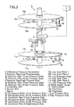
- FIG. 3 is a schematic view showing the configuration of a first embodiment according to the present invention.
- the numeral 6 indicates a sensor unit to which a stand (7), a straightner plate 1 (low pressure side) (8a), a straightner plate 2 (low pressure side) (8b), a detector pipe 1 (low pressure side) (3a), a detector pipe 2 (low pressure side) (3b), a detector pipe (low pressure side) (3), a straightner plate 1 (high pressure side) (9a), a straightner plate 2 (high pressure side) (9b), a detector pipe 1 (high pressure side) (4a), a detector pipe 2 (high pressure side) (4b), a detector pipe (high pressure side) 4, a differential pressure transmitter (2), a low side plate 1 (10a), a low side plate 2 (10b), a high side plate 1 (11a), and a high side plate 2 (lib) are fixed so as to be integral with the sensor unit and the sensor unit is submerged in the stream flow of a dam, river or the like.
- the low side plates 1 (10a) and 2 (10b) Fixed onto the upper section of the stand (7) are the low side plates 1 (10a) and 2 (10b) which are circular, for example, and provided as first ripple removal means, wherein the plates 1 (10a) and 2 (10b) are separated at a given distance from each other with the stand (7) penetrating through the center points thereof.
- a low pressure area 10c is thus formed in the space between the low side plates 1 (10a) and 2 (10b).
- the high side plates 1 (11a) and 2 (11b), which are also circular, for example, and provided as second ripple removal means, are fixed onto the stand (7) at a position downward (in the depth direction of the stream flow) from the low side plates 1 (10a) and 2 (10b), wherein the plates 1 (11a) and 2 (11b) are separated at a given distance from each other with the stand (7) penetrating through the center points thereof.
- a high pressure area 11c is thus formed in a space between the high side plates 1 (11a) and 2 (11b).
- differential pressure transmitter (2) Fixed between the high side plate 1 (11a) and the low side plate 2 (10b) on the stand (7) is the differential pressure transmitter (2).
- a water depth gauge (12) and a thermometer (13) are fixed in the vicinity of the differential pressure transmitter (2).
- a flowmeter 14a is fixed onto the low side plate 1 (10a) so as to be positioned in the low pressure area 10c.
- a flowmeter 14b is fixed onto the high side plate 1 (11a) so as to be positioned in the high pressure area 11c.
- the straightner plate 1 (low pressure side) (8a) and straightner plate 2 (low pressure side) (8b), which are also circular, for example, and provided as first ripple removal means, are connected to each other with a connection rod (8c) so as to be opposite to each other and positioned in the low pressure area 10c, both being fixed onto the low side plate 1 (10a). More specifically, the straightner plate 1 (low pressure side) (8a) and straightner plate 2 (low pressure side) (8b) are arranged so that the surfaces thereof are virtually perpendicular to those of the low side plates 1 (10a) and 2 (10b).
- FIG. 4a is a side view showing the way the straightner plate 1 (low pressure side) (8a) and straightner plate 2 (low pressure side) (8b) are connected to each other
- FIG. 4b is a plan view of the straightner plate 1 (low pressure side) (8a) (or straightner plate 2 (low pressure side) (8b)).
- a low side pressure hole 1 (8d) is formed in the straightner plate 1 (high pressure side) (8a) to introduce the pressure of water in contact with one side thereof opposite to the straightner plate 2 (low pressure side) (8b) when the straightner plate 1 (low pressure side) (8a) is submerged in a stream flow such as water.
- a low side tube 1 (8e) leading into the low side pressure hole 1 (8d) is connected to the straightner plate 1 (low pressure side) (8a).
- the tip of the detector pipe 1 (low pressure side) (3a) is connected to the low side tube 1 (8e) so as to lead into the low side pressure hole 1 (8d).
- a low side pressure hole 2 (8f) is formed in the straightner plate 2 (low pressure side) (8b) in a position virtually level with the low side pressure hole 1 (8d), in order to introduce the pressure of water in contact with one side of the straightner plate 2 (low pressure side) (8b) opposite to the straightner plate 1 (low pressure side) (8a).
- a low side tube 2 (8g) leading into the low side pressure hole 2 (8f) is connected to the straightner plate 2 (low pressure side) (8b).
- the tip of the detector pipe 2 (low pressure side) (3b) is connected to the low side tube 2 (8g) so as to lead into the low side pressure hole 2 (8f).
- the detector pipe 1 (low pressure side) (3a) and detector pipe 2 (high pressure side) (3b) are made to join into a single detector pipe, i.e., the detector pipe (low pressure side) (3).
- the detector pipe (low pressure side) (3) is connected to the low pressure side L of the differential pressure transmitter (2).
- the detector pipe 1 (low pressure side) (3a), detector pipe 2 (low pressure side) (3b) and detector pipe (low pressure side) (3) are sealed with a sealing fluid, such as water.
- the high-pressure side of the sensor unit (6) is configured to be similar to the low-pressure side thereof. More specifically, straightner plate 1 (low pressure side) (9a) and straightner plate 2 (low pressure side) (9b), which are circular, for example, and provided as second ripple removal means, are connected to each other with a connection rod (9c) so as to be opposite to each other and positioned in the high pressure area 11c, both being fixed onto the high side plate 1 (11a). Yet more specifically, the straightner plate 1 (low pressure side) (9a) and straightner plate 2 (low pressure side) (9b) are arranged so that the surfaces thereof are virtually perpendicular to those of the high side plates 1 (11a) and 2 (11b).
- the straightner plate 1 (low pressure side) (9a) and straightner plate 2 (low pressure side) (9b) are structurally the same as the straightner plate 1 (low pressure side) (8a) and straightner plate 2 (low pressure side) (8b) shown in FIGS. 4a and 4b. That is, a high side pressure hole 1 (9d) is formed in the straightner plate 1 (high pressure side) (9a) to introduce the pressure of water in contact with one side thereof opposite to the straightner plate 2 (high pressure side) (9b) when the straightner plate 1 (high pressure side) (9a) is submerged in the liquid of a stream flow such as water.
- a high side tube 1 (9e) leading into the high side pressure hole 1 (9d) is connected to the straightner plate 1 (high pressure side) (9a). Additionally, as shown in FIG. 3, the tip of the detector pipe 1 (high pressure side) (4a) is connected to the high side tube 1 (9e) so as to lead into the high side pressure hole 1 (9d).
- a high side pressure hole 2 (9f) is formed in the straightner plate 2 (high pressure side) (9b) in a position virtually level with the high side pressure hole 1 (9d), in order to introduce the pressure of water in contact with one side of the straightner plate 2 (high pressure side) (9b) opposite to the straightner plate 1 (high pressure side) (9a).
- a high side tube 2 (9g) leading into the high side pressure hole 2 (9f) is connected to the straightner plate 2 (high pressure side) (9b).
- the tip of the detector pipe 2 (high pressure side) (4b) is connected to the high side tube 2 (9g) so as to lead into the high side pressure hole 2 (9f).
- the detector pipe 1 (high pressure side) (4a) and detector pipe 2 (high pressure side) (4b) are made to join into a single detector pipe, i.e., the detector pipe (high pressure side) 4.
- the detector pipe (high pressure side) (4) is connected to the high pressure side H of the differential pressure transmitter (2).
- the detector pipe 1 (high pressure side) (4a), detector pipe 2 (high pressure side) (4b) and detector pipe (high pressure side) (4) are sealed with a sealing fluid, such as water.
- the sensor unit (6) is submerged in the liquid of a dam, river or the like. If the liquid is running, the sensor unit (6) is oriented and submerged therein so that the liquid flows between the straightner plate 1 (low pressure side) (8a) and straightner plate 2 (low pressure side) (8b) and between the straightner plate 1 (low pressure side) (9a) and straightner plate 2 (low pressure side) (9b).
- the pressure of liquid flowing between the straightner plate 1 (low pressure side) (8a) and straightner plate 2 (low pressure side) (8b) is introduced through the low side pressure hole 1 (8d) into the detector pipe 1 (low pressure side) (3a), thus pressurizing the fluid sealed therein.
- the pressure is also introduced through the low side pressure hole 2 (8f) into the detector pipe 2 (low pressure side) (3b). Since the detector pipe 1 (low pressure side) (3a) and detector pipe 2 (low pressure side) (3b) are made to join into the detector pipe (low pressure side) (3), the pressures introduced to the two pipes 1 (3a) and 2 (3b) are averaged and the resulting average pressure is introduced through the detector pipe (low pressure side) (3) to the low pressure side L of the differential pressure transmitter (2).
- the straightner plate 1 (low pressure side) (8a) and straightner plate 2 (low pressure side) (8b) remove ripples and thereby streamline the flow of liquid by limiting the region through which the liquid flows, so that an influence exerted upon pressure detection by horizontal waves, in particular, produced in the direction perpendicular to the surfaces of the straightner plate 1 (low pressure side) (8a) and straightner plate 2 (low pressure side) (8b) is reduced.
- the low side plates 1 (10a) and 2 (10b) remove ripples and thereby streamline the flow of the liquid by limiting the region through which the liquid flows to the area 10c only, so that an influence exerted upon pressure detection by vertical waves, in particular, produced in the depth direction of the liquid is reduced.
- the differential pressure transmitter (2) detects the difference between the low and high pressures applied thereto by means of the diaphragm built therein (not shown in the figure) and converts the difference to an electric signal.
- the computing unit (5) calculates the average density of liquid between the low side pressure hole 1 (8d) (or low side pressure hole 2 (8f)) and the high side pressure hole 1 (9d) (or high side pressure hole 2 (9f)). Then, the computing unit (5) calculates the difference between the average density thus evaluated and the previously evaluated and stored reference density of the liquid as an index for determining suspended-substance concentrations.
- corrections are made to the measured density and the output of the differential pressure transmitter (2), according to previously obtained data on a change in the density of water with temperature and the temperature characteristic of the differential pressure transmitter (2), such as those shown in FIGS. 2a and 2b.
- the values measured as described above are also utilized as reference data representing conditions for measuring suspended-substance concentrations.
- a low side pressure hole may only be formed in either the straightner plate 1 (low pressure side) (8a) or the straightner plate 2 (low pressure side) (8b). Then, the detector pipe (low pressure side) (3) may be connected to either the straightner plate 1 (low pressure side) (8a) or the straightner plate 2 (low pressure side) (8b) so as to lead into the low side pressure hole.
- a high-side pressure hole may only be formed in either the straightner plate 1 (high pressure side) (9a) or the straightner plate 2 (high pressure side) (9b). Then, the detector pipe (high pressure side) (4) may be connected to either the straightner plate 1 (high pressure side) (9a) or the straightner plate 2 (high pressure side) (9b) so as to lead into the high-side pressure hole.
- the pressure difference between two points distantly located in the depth direction of a liquid is detected using the differential pressure transmitter (2) without resort to optical measurement means, the average liquid density between the two points is calculated according to the detected pressure difference, and the difference between the average density and the reference density of the liquid is used as an index for determining suspended-substance concentrations. Consequently, it is possible to measure the concentration precisely, continuously, and in real time, while keeping the sensor unit (6) submerged for a long period of time. Thus, the work of maintaining and controlling the apparatus can be reduced only to such tasks as the zero-point adjustment of the differential pressure transmitter (2). Additionally, since the measuring range is dependent on the measurement accuracy of the differential pressure transmitter (2), it is also possible to measure the concentration over a broad range, for example, as wide as from 30 ppm to 70000 ppm.
- FIG. 5 is a schematic view showing the configuration of a second embodiment according to the present invention.
- the straightner plate 1 (low pressure side) (8a) and straightner plate 2 (low pressure side) (8b) shown in the apparatus for measuring suspended-substance concentrations illustrated in FIG. 3 are replaced with a low side straightner pipe (15) provided as first ripple removal means.
- the straightner plate 1 (low pressure side) (9a) and straightner plate 2 (low pressure side) (9b) are replaced with a high side straightner pipe (16) provided as second ripple removal means. Accordingly, components identical to those of FIG. 3 are referenced alike and excluded from the explanation as necessary.
- FIG. 6a is a perspective view showing the configuration of the low side straightner pipe (15) (or high side straightner pipe (16)), whereas FIG. 6b is a schematic cross-section thereof as viewed from the line AA'.
- a low side pressure hole 1 (15a) is formed in the low side straightner pipe (15) to introduce the pressure of water in contact with the inside thereof when the low side straightner pipe (15) is submerged in water.
- a low side tube 1 (15b) leading into the low side pressure hole 1 (15a) is connected to the low side straightner pipe (15).
- the tip of the detector pipe 1 (low pressure side) (3a) is connected to the low side tube 1 (15b) so as to lead into the low side pressure hole 1 (15a).
- a low side pressure hole 2 (15c) leading inside the low side straightner pipe (15) is formed therein in a position opposite to the low side pressure hole 1 (15a), wherein a low side tube 2 (15d) leading into the low side pressure hole 2 (15c) is connected to the low side straightner pipe (15). Additionally, as shown in FIG. 5, the tip of the detector pipe 2 (low pressure side) (3b) is connected to the low side tube 2 (15d) so as to lead into the low side pressure hole 2 (15c).
- the high side straightner pipe (16) is structurally the same as the low side straightner pipe (15) shown in FIGS. 6a and 6b. That is, a high side pressure hole 1 (16a) is formed in the high side straightner pipe (16) to introduce the pressure of water in contact with the inside thereof when the high side straightner pipe (16) is submerged in water. A high side tube 1 (16b) leading into the high side pressure hole 1 (16a) is connected to the high side straightner pipe (16). Additionally, as shown in FIG. 5, the tip of the detector pipe 1 (high pressure side) (4a) is connected to the high side tube 1 (16b) so as to lead into the high side pressure hole 1 (16a).
- a high side pressure hole 2 (16c) leading inside the high side straightner pipe (16) is formed therein in a position opposite to the high side pressure hole 1 (16a), wherein a low side tube 2 (16d) leading into the high side pressure hole 2 (16c) is connected to the high side straightner pipe (15). Additionally, as shown in FIG. 5, the tip of the detector pipe 2 (high pressure side) (4b) is connected to the high side tube 2 (16d) so as to lead into the high side pressure hole 2 (16c).
- the sensor unit (6) is submerged in the liquid of a dam, river or the like. If the liquid is running, the sensor unit (6) is oriented and submerged therein so that the liquid flows through the low side straightner pipe (15) and high side straightner pipe (16).
- the low side straightner pipe (15) (high side straightner pipe (16)) removes ripples and thereby streamlines the flow of liquid by limiting the region through which the liquid flows, so that influences exerted upon pressure detection by horizontal and vertical waves produced in the directions perpendicular to and parallel with the cross-section of the low side straightner pipe (15) (high side straightner pipe (16)) are reduced.
- the detector pipe (low pressure side) (3) may be connected to low side straightner pipe (15) so as to lead into the low side pressure hole.
- the detector pipe (high pressure side) (4) may be connected to the high side straightner pipe (16) so as to lead into the high-side pressure hole.
- FIG. 7 is a schematic view showing the configuration of a third embodiment according to the present invention.
- low side and high side support plates 17 and 18 are provided in place of the straightner plate 2 (low pressure side) (8b) and straightner plate 2 (high pressure side) (9b), respectively, shown in the apparatus for measuring suspended-substance concentrations illustrated in FIG. 3.
- the detector pipe (low pressure side) (3) and detector pipe (high pressure side) (4) are replaced with low side and high side capillary tubes 19 and 20, respectively. Accordingly, components identical to those of FIG. 3 are referenced alike and excluded from the explanation as necessary.
- low side and high side support plates 17 and 18 may be provided in place of the straightner plate 1 (low pressure side) (8a) and straightner plate 1 (high pressure side) (9a), respectively, shown in the apparatus for measuring suspended-substance concentrations illustrated in FIG. 3.
- a low side diaphragm seal (21), wherein the low side capillary tube (19) is fixed to the low side support plate (17) so as to lead into the inside thereof.
- the low side support plate (17) and low side capillary tube (19) are sealed with a sealing fluid, and a pressure detected by the low side diaphragm seal (21) is input through the low side capillary tube (19) to the differential pressure transmitter (2).
- a high side diaphragm seal (22) is fixed onto one side of the high side support plate (18) opposite to the straightner plate 1 (high pressure side) (9a), wherein the high side capillary tube (20) is fixed to the high side support plate (18) so as to lead into the inside thereof.
- the high side support plate (18) and high side capillary tube (20) are sealed with a sealing fluid, and a pressure detected by the high side diaphragm seal (22) is input through the high side capillary tube (20) to the differential pressure transmitter (2).
- the low side support plate (17) functions as a straightner plate 2 (low pressure side) and the high side support plate (18) functions as a straightner plate 2 (high pressure side)
- the low side and high side support plates 17 and 18 may be used in combination with the straightner plate 1 (low pressure side) (8a) and the straightner plate 1 (high pressure side) (9a), respectively.
- the combination of the low side support plate (17) and straightner plate 1 (low pressure side) (8a) removes ripples and thereby streamlines the flow of liquid by limiting the region through which the liquid flows, so that an influence exerted upon pressure detection by horizontal waves, in particular, produced in the direction perpendicular to the surfaces of the straightner plate 1 (low pressure side) (8a) and low side support plate (17) (straightner plate 1 (high pressure side) (9a) and high side support plate (18)) is reduced.
- the apparatus Since the pressure detection units of such an apparatus for measuring suspended-substance concentrations as described above are diaphragm seals, the apparatus features higher levels of noise immunity performance against such suspended substances as earth and sand or dirt, compared with apparatus based on pressure detection pipes. Thus, the apparatus is suited for measurement of suspended-substance concentrations in the depths of a dam.
- a sealing fluid with which the low side and high side capillary tubes 19 and 20 are sealed and which contains no suspended substance, and a liquid under test containing suspended substances are of the same type (water, for example).
- the sealing fluid is silicone oil, for example, temperature-based density corrections may be made for the liquid under test (water, for example) and the silicone oil. This strategy will enable the apparatus to measure suspended-substance concentrations more precisely.
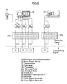
- FIG. 8 is a schematic view showing the configuration of an apparatus for measuring suspended-substance concentrations according to the present invention, wherein such peripheral equipment as a recorder and a handheld terminal are connected to the apparatus.
- a differential pressure transmitter (2), a water depth gauge 12, and a thermometer (13) are located on the signal-transmitting side, each being connected to a terminal plate (23a) located on the signal-receiving side.
- Distributors 24a, 24b and 24c located on the signal-receiving side are connected to a terminal plate (23a), wherein a handheld terminal (H.H.T.) (25) is connected to the distributor (24a).
- a recorder (26) is connected to the distributors 24a, 24b and 24c.
- a flowmeter 14 located on the signal-transmitting side and a pulse signal receiver (27) located on the signal-receiving side are connected to a terminal plate (23b), wherein a pulse signal recorder (28) is connected to the pulse signal receiver (27).
- Output signals of 4 to 20 mA are provided by the differential pressure transmitter (2), water depth gauge 12 and thermometer (13).
- Input to the recorder (26) are signals of 1 to 5 V, for example, resulting from conversion of the output signals at the distributors 24a, 24b and 24c.
- the recorder (26) functions as a computing unit, which performs such tasks as computing suspended-substance concentrations and making corrective calculations according to outputs from the water depth gauge 12 and thermometer (13), and records and displays the results of these tasks.
- corrections are made to the measured density and the output of the differential pressure transmitter (2), according to previously obtained data on a change in the density of water with temperature and the temperature characteristic of the differential pressure transmitter (2), such as those shown in FIGS. 2a and 2b, as well as to the temperature of water and the ambient temperature of the differential pressure transmitter (2) simultaneously measured with the thermometer (13).
- the handheld terminal (25) is used to externally send signals for making the zero-point adjustment (reference density setting) of the differential pressure transmitter (2), setting the alarm and changing parameters, through the distributor (24a), to the differential pressure transmitter (2).
- the flowmeter 14 is provided with a rotor driven by running water, for example, and the pulse signal receiver (27) emits a buzzer sound once every five revolutions, for example, made by the rotor of the flowmeter 14.
- the pulse signal recorder (28) receives the frequency of buzzer sound emitted from the pulse signal receiver (27) as the frequency of pulses, measures the buzzer sound frequency for a given period of time, calculates the revolutions-per-second value of the rotor from the measured frequency, and evaluates the flow speed of the running water. The flow speed thus evaluated is used as reference data at a point in time when a suspended-substance concentration is measured.
- FIG. 9 is a schematic view showing the configuration of a shell wherein the sensor unit shown in FIG. 3 is housed.
- a shell (29) is a hollow cylinder, consisting of circular upper plate (30), a circular lower plate (31), and a cylindrical side plate (32).
- Stream inlet outlet holes (30a) are formed in the upper plate (30)
- stream inlet outlet holes (31a) are formed in the lower plate (31)
- stream inlet outlet holes (32a) are formed in the side plate (32). Note that in FIG. 9, the cross-sections of only main parts are shown with regard to the side plate (32) for the purpose of simplifying the drawing. Also note that the stream inlet outlet holes (30a), (31a) and (32a) may be provided with filters as necessary.
- the sensor unit (6) is housed in the shell (29) and the shell (29) is submerged in a stream flow, so that the stream flow is introduced therein through the stream inlet outlet holes (30a), 30b and 30c and the suspended-substance concentration of the stream flow is measured.
- This method of measurement can prevent parts of a component mounted on the sensor unit (6), for example, the differential pressure transmitter (2), from being damaged by such foreign matter contained in the stream flow as gravel, driftwood or dirt. Additionally, the method helps increase the effect of streamlining the stream flow by housing the sensor unit (6) in the shell (29) wherein the stream inlet outlet holes (30a), (31a) and (32a) are formed. Yet additionally, it is possible to measure suspended-substance concentrations precisely and consistently by keeping uniform the ambient temperature of components, such as the differential pressure transmitter (2), mounted on the sensor unit (6).
- the pressure difference between two points distantly located in the depth direction of a liquid is detected without resort to optical measurement means, and the suspended-substance concentration of the liquid is measured according to the detected pressure difference. Consequently, it is possible to provide a method for measuring suspended-substance concentrations that allows for real-time, continuous measurement and easy maintenance and control of apparatus and provides high measurement accuracy and wide measuring ranges.
- an ambient temperature and the temperature of a liquid at which the pressure difference is detected are measured, the pressure difference is temperature-corrected according to the measured ambient temperature, and the average density is also temperature-corrected according to the measured temperature of the liquid. Consequently, it is possible to measure suspended-substance concentrations more precisely.
- a differential pressure transmitter for detecting the pressure difference between two points distantly located in the depth direction of a liquid without resort to optical measurement means. Consequently, it is possible to provide an apparatus for measuring suspended-substance concentrations that allows for real-time, continuous measurement and easy maintenance and control and provides high measurement accuracy and wide measuring ranges.
- detector pipes low pressure side and high pressure side
- the same liquid in which no suspended substance is mixed
- ripple removal means for removing liquid ripples produced near pressure detector units for detecting the pressure difference between two points distantly located in the depth direction of a liquid. Consequently, it is possible to provide an apparatus for precisely measuring suspended-substance concentrations.
- a sensor unit to which pressure detector units, a differential pressure transmitter and ripple removal means are fixed so as to be integral therewith. Consequently, it is possible to provide an apparatus for measuring suspended-substance concentrations that allows for real-time, continuous measurement.
- a seventh aspect of the present invention there are provided straightner plates for removing horizontal liquid ripples produced near pressure detector units for detecting the pressure difference between two points distantly located in the depth direction of a liquid. Consequently, it is possible to provide an apparatus for precisely measuring suspended-substance concentrations.
- partition plates for removing vertical liquid ripples produced near pressure detector units for detecting the pressure difference between two points distantly located in the depth direction of a liquid. Consequently, it is possible to provide an apparatus for precisely measuring suspended-substance concentrations.
- a sensor unit to which pressure detector units, a differential pressure transmitter, straightner plates, and partition plates are fixed so as to be integral therewith. Consequently, it is possible to provide an apparatus for measuring suspended-substance concentrations that allows for real-time, continuous measurement.
- straightner plates for removing horizontal liquid ripples produced near pressure detector units for detecting the pressure difference between two points distantly located in the depth direction of a liquid, and the average pressure obtained by averaging pressures detected by first and second low-pressure side (high-pressure side) detector units is input to a differential pressure transmitter. Consequently, it is possible to provide an apparatus for precisely measuring suspended-substance concentrations.
- straightner pipes for removing horizontal and vertical liquid ripples produced near pressure detector units for detecting the pressure difference between two points distantly located in the depth direction of a liquid. Consequently, it is possible to provide an apparatus for precisely measuring suspended-substance concentrations.
- a sensor unit to which pressure detector units, a differential pressure transmitter, straightner pipes, and partition plates are fixed so as to be integral therewith. Consequently, it is possible to provide an apparatus for measuring suspended-substance concentrations that allows for real-time, continuous measurement.
- straightner pipes for removing horizontal and vertical liquid ripples produced near pressure detector units for detecting the pressure difference between two points distantly located in the depth direction of a liquid, and the average pressure obtained by averaging pressures detected by first and second low-pressure side (high-pressure side) detector units is input to a differential pressure transmitter. Consequently, it is possible to provide an apparatus for precisely measuring suspended-substance concentrations.
- a fourteenth aspect of the present invention there are provided straightner plates for removing horizontal liquid ripples produced near diaphragm seals for detecting the pressure difference between two points distantly located in the depth direction of a liquid. Consequently, it is possible to provide an apparatus for precisely measuring suspended-substance concentrations.
- partition plates for removing vertical liquid ripples produced near diaphragm seals for detecting the pressure difference between two points distantly located in the depth direction of a liquid for detecting the pressure difference between two points distantly located in the depth direction of a liquid. Consequently, it is possible to provide an apparatus for precisely measuring suspended-substance concentrations.
- a sensor unit to which diaphragm seals, a differential pressure transmitter, straightner plates, and partition plates are fixed so as to be integral therewith. Consequently, it is possible to provide an apparatus for measuring suspended-substance concentrations that allows for real-time, continuous measurement.
- a sensor unit is housed in a shell wherein stream inlet outlet holes for a liquid to pass through are formed. Consequently, it is possible to prevent parts of a component mounted on the sensor unit, for example, a differential pressure transmitter, from being damaged, increase the effect of streamlining the liquid, and measure suspended-substance concentrations more precisely and consistently by keeping uniform the ambient temperature of components, such as the differential pressure transmitter, mounted on the sensor unit.
- a component mounted on the sensor unit for example, a differential pressure transmitter
Landscapes
- Physics & Mathematics (AREA)
- Health & Medical Sciences (AREA)
- Life Sciences & Earth Sciences (AREA)
- Chemical & Material Sciences (AREA)
- Analytical Chemistry (AREA)
- Biochemistry (AREA)
- General Health & Medical Sciences (AREA)
- General Physics & Mathematics (AREA)
- Immunology (AREA)
- Pathology (AREA)
- Measuring Fluid Pressure (AREA)
- Investigating Or Analyzing Materials By The Use Of Ultrasonic Waves (AREA)
- Automatic Analysis And Handling Materials Therefor (AREA)
Abstract
Description
Claims (22)
- A method for measuring the concentration of suspended substances mixed with a liquid, wherein the pressure difference between two points distantly located in the depth direction of said liquid is detected, the average density of said liquid between said two points is calculated from said pressure difference, and the difference between said average density and the predetermined reference density of said liquid is calculated as an index for determining said suspended-substance concentration.
- The method of claim 1, wherein an ambient temperature at which said pressure difference is detected and the temperature of said liquid are measured, said pressure difference is temperature-corrected according to the measured ambient temperature, and said average density is also temperature-corrected according to the measured temperature of said liquid.
- An apparatus to be submerged in a liquid in which suspended substances are mixed in order to measure the suspended-substance concentration of said liquid, comprising:low-pressure side and high-pressure side detector units submerged down to two points distantly located in the depth direction of said liquid;a differential pressure transmitter for converting the difference between pressures detected by said low-pressure side and high-pressure side detector units to an electric signal; anda computing unit for calculating the average density of said liquid between said two points according to the output of said differential pressure transmitter and further calculating the difference between said average density and the predetermined reference density of said liquid as an index for determining said suspended-substance concentration.
- The apparatus of claim 3, wherein said low-pressure side detector unit is a detector pipe (low pressure side) connected to said differential pressure transmitter and sealed with said liquid in which none of said suspended substances is mixed and said high-pressure side detector unit is a detector pipe (high pressure side) also connected to said differential pressure transmitter and sealed with said liquid in which none of said suspended substances is mixed either.
- The apparatus of claim 3, further comprising:first ripple removal means arranged in the vicinity of said detector pipe (low pressure side) in order to remove ripples of said liquid produced near said detector pipe (low pressure side); andsecond ripple removal means arranged in the vicinity of said detector pipe (high pressure side) in order to remove ripples of said liquid produced near said detector pipe (high pressure side).
- The apparatus of claim 5 having a sensor unit, wherein said detector pipe (low pressure side), said detector pipe (high pressure side), said differential pressure transmitter, said first ripple removal means, and said second ripple removal means are fixed to said sensor unit so as to be integral therewith and said sensor unit is submerged in said liquid.
- An apparatus to be submerged in a liquid in which suspended substances are mixed in order to measure the suspended-substance concentration of said liquid, comprising:first and second low-pressure side straightner plates which are flat and submerged in said liquid with the surfaces thereof positioned virtually perpendicular to said liquid's surface, while being arranged to be distant from and opposite to each other;a low-side pressure hole provided on either of the opposing surfaces of said first and second low-pressure side straightner plates;a detector pipe (low pressure side) connected to either of said first and second low-pressure side straightner plates so as to lead into said low-side pressure hole;first and second high-pressure side straightner plates which are flat and submerged in the depth direction of said liquid distantly from said first and second low-pressure side straightner plates, with the surfaces thereof positioned virtually perpendicular to said liquid's surface, while being arranged to be distant from and opposite to each other;a high-side pressure hole provided on either of the opposing surfaces of said first and second high-pressure side straightner plates;a detector pipe (high pressure side) connected to either of said first and second high-pressure side straightner plates so as to lead into said high-side pressure hole;a differential pressure transmitter for converting the difference between pressures detected by said detector pipe (low pressure side) and said detector pipe (high pressure side) to an electric signal; anda computing unit for calculating the average density of said liquid according to the output of said differential pressure transmitter and further calculating the difference between said average density and the predetermined reference density of said liquid as an index for determining said suspended-substance concentration.
- The apparatus of claim 7, further comprising:first and second low-pressure side plates which are flat and arranged to be distant from each other in the depth direction of said liquid so as to sandwich said first and second low-pressure side straightner plates; andfirst and second high-pressure side plates which are flat and arranged to be distant from each other in the depth direction of said liquid so as to sandwich said first and second high-pressure side straightner plates.
- The apparatus of claim 8 having a sensor unit, wherein said first low-pressure side straightner plate, said second low-pressure side straightner plate, said detector pipe (low pressure side), said first high-pressure side straightner plate, said second high-pressure side straightner plate, said detector pipe (high pressure side), said differential pressure transmitter, said first low-pressure side plate, said second low-pressure side plate, said first high-pressure side plate, and said second high-pressure side plate are fixed to said sensor unit so as to be integral therewith and said sensor unit is submerged in said liquid.
- An apparatus to be submerged in a liquid in which suspended substances are mixed in order to measure the suspended-substance concentration of said liquid, comprising:a first low-pressure side straightner plate which is flat and submerged in said liquid with the surfaces thereof positioned virtually perpendicular to said liquid's surface, wherein a first low-side pressure hole is formed on one side of said first low-pressure side straightner plate;a first low-pressure side detector pipe connected to said first low-pressure side straightner plate so as to lead into said first low-side pressure hole;a second low-pressure side straightner plate which is flat and arranged to be distant from and opposite to one side of said first low-pressure side straightner plate and a second low-side pressure hole is formed on the side of said second low-pressure side straightner plate opposite to said first low-pressure side straightner plate;a second low-pressure side detector pipe connected to said second low-pressure side straightner plate so as to lead into said second low-side pressure hole;a first high-pressure side straightner plate which is flat and submerged in said liquid with the surfaces thereof positioned virtually perpendicular to said liquid's surface, while being made distant from said low-pressure side straightner plate in the depth direction of said liquid, wherein a first high-side pressure hole is formed on one side of said first high-pressure side straightner plate;a first high-pressure side detector pipe connected to said first high-pressure side straightner plate so as to lead into said first high-side pressure hole;a second high-pressure side straightner plate which is flat and arranged to be distant from and opposite to one side of said first high-pressure side straightner plate and a second high-side pressure hole is formed on the side of said second high-pressure side straightner plate opposite to said first high-pressure side straightner plate;a second high-pressure side detector pipe connected to said second high-pressure side straightner plate so as to lead into said second high-side pressure hole;a differential pressure transmitter for converting the pressure difference between the average pressure obtained by averaging pressures detected by said first and second low-pressure side detector pipes and the average pressure obtained by averaging pressures detected by said first and second high-pressure side detector pipes to an electric signal; anda computing unit for calculating the average density of said liquid according to the output of said differential pressure transmitter and further calculating the difference between said average density and the predetermined reference density of said liquid as an index for determining said suspended-substance concentration.
- The apparatus of claim 10, further comprising:first and second low-pressure side plates which are flat and arranged to be distant from each other in the depth direction of said liquid so as to sandwich said first and second low-pressure side straightner plates; andfirst and second high-pressure side plates which are flat and arranged to be distant from each other in the depth direction of said liquid so as to sandwich said first and second high-pressure side straightner plates.
- The apparatus of claim 11 having a sensor unit, wherein said first low-pressure side straightner plate, said first low-pressure side detector pipe, said second low-pressure side straightner plate, said second low-pressure side detector pipe, said first high-pressure side straightner plate, said first high-pressure side detector pipe, said second high-pressure side straightner plate, said second high-pressure side detector pipe, said differential pressure transmitter, said first low-pressure side plate, said second low-pressure side plate, said first high-pressure side plate, and said second high-pressure side plate are fixed to said sensor unit so as to be integral therewith and said sensor unit is submerged in said liquid.
- An apparatus to be submerged in a liquid in which suspended substances are mixed in order to measure the suspended-substance concentration of said liquid, comprising:a low-pressure side straightner pipe which is tubular and submerged in said liquid with the central axis thereof positioned virtually parallel with said liquid's surface, wherein a low-side pressure hole leading inside said low-pressure side straightner pipe is formed in said low-pressure side straightner pipe;a detector pipe (low pressure side) connected to said low-pressure side straightner pipe so as to lead into said low-side pressure hole;a high-pressure side straightner pipe which is tubular and submerged in said liquid with the central axis thereof positioned virtually parallel with said liquid's surface, while being made distant from said low-pressure side straightner pipe in the depth direction of said liquid, and wherein a high-side pressure hole leading inside said high-pressure side straightner pipe is formed;a detector pipe (high pressure side) connected to said high-pressure side straightner pipe so as to lead into said high-side pressure hole;a differential pressure transmitter for converting the pressure difference between pressures detected by said detector pipe (low pressure side) and said detector pipe (high pressure side) to an electric signal; anda computing unit for calculating the average density of said liquid according to the output of said differential pressure transmitter and further calculating the difference between said average density and the predetermined reference density of said liquid as an index for determining said suspended-substance concentration.
- The apparatus of claim 13, further comprising:first and second low-pressure side plates which are flat and arranged to be distant from each other in the depth direction of said liquid so as to sandwich said low-pressure side straightner pipes; andfirst and second high-pressure side plates which are flat and arranged to be distant from each other in the depth direction of said liquid so as to sandwich said high-pressure side straightner pipe.
- The apparatus of claim 14 having a sensor unit, wherein said low-pressure side straightner pipe, said detector pipe (low pressure side), said high-pressure side straightner pipe, said detector pipe (high pressure side), said differential pressure transmitter, said first low-pressure side plate, said second low-pressure side plate, said first high-pressure side plate, and said second high-pressure side plate are fixed to said sensor unit so as to be integral therewith and said sensor unit is submerged in said liquid.
- An apparatus to be submerged in a liquid in which suspended substances are mixed in order to measure the suspended-substance concentration of said liquid, comprising:a low-pressure side straightner pipe which is tubular and submerged in said liquid with the central axis thereof positioned virtually parallel with said liquid's surface and wherein a first low-side pressure hole leading inside said low-pressure side straightner pipe and a second low-side pressure hole positioned opposite to said first low-side pressure hole and also leading inside said low-pressure side straightner pipe are formed;a first low-pressure side detector pipe connected to said low-pressure side straightner pipe so as to lead into said first low-side pressure hole;a second low-pressure side detector pipe connected to said low-pressure side straightner pipe so as to lead into said second low-side pressure hole;a high-pressure side straightner pipe which is tubular and submerged in said liquid with the central axis thereof positioned virtually parallel with said liquid's surface, while being made distant from said low-pressure side straightner pipe in the depth direction of said liquid, and wherein a first high-side pressure hole leading inside said high-pressure side straightner pipe and a second high-side pressure hole positioned opposite to said first high-side pressure hole and also leading inside said high-pressure side straightner pipe are formed;a first high-pressure side detector pipe connected to said high-pressure side straightner pipe so as to lead into said first high-side pressure hole;a second high-pressure side detector pipe connected to said high-pressure side straightner pipe so as to lead into said second high-side pressure hole;a differential pressure transmitter for converting the pressure difference between the average pressure obtained by averaging pressures detected by said first and second low-pressure side detector pipes and the average pressure obtained by averaging pressures detected by said first and second high-pressure side detector pipes to an electric signal; anda computing unit for calculating the average density of said liquid according to the output of said differential pressure transmitter and further calculating the difference between said average density and the predetermined reference density of said liquid as an index for determining said suspended-substance concentration.
- The apparatus of claim 16, further comprising:first and second low-pressure side plates which are flat and arranged to be distant from each other in the depth direction of said liquid so as to sandwich said low-pressure side straightner pipe; andfirst and second high-pressure side plates which are flat and arranged to be distant from each other in the depth direction of said liquid so as to sandwich said high-pressure side straightner pipe.
- The apparatus of claim 17 having a sensor unit, wherein said low-pressure side straightner pipe, said first low-pressure side detector pipe, said second low-pressure side detector pipe, said high-pressure side straightner pipe, said first high-pressure side detector pipe, said second high-pressure side detector pipe, said differential pressure transmitter, said first low-pressure side plate, said second low-pressure side plate, said first high-pressure side plate, and said second high-pressure side plate are fixed to said sensor unit so as to be integral therewith and said sensor unit is submerged in said liquid.
- An apparatus to be submerged in a liquid in which suspended substances are mixed in order to measure the suspended-substance concentration of said liquid, comprising:first and second low-pressure side straightner plates which are flat and submerged in said liquid with the surfaces thereof positioned virtually perpendicular to said liquid's surface, while being arranged to be distant from and opposite to each other;a low-pressure side diaphragm seal provided on either of the opposing surfaces of said first and second low-pressure side straightner plates;first and second high-pressure side straightner plates which are flat and submerged in the depth direction of said liquid distantly from said first and second low-pressure side straightner plates, with the surfaces thereof positioned virtually perpendicular to said liquid's surface, while being arranged to be distant from and opposite to each other;a high-pressure side diaphragm seal provided on either of the opposing surfaces of said first and second high-pressure side straightner plates;a differential pressure transmitter for converting the difference between pressures detected by said low-pressure side and high-pressure side diaphragm seals to an electric signal; anda computing unit for calculating the average density of said liquid according to the output of said differential pressure transmitter and further calculating the difference between said average density and the predetermined reference density of said liquid as an index for determining said suspended-substance concentration.
- The apparatus of claim 19, further comprising:first and second low-pressure side plates which are flat and arranged to be distant from each other in the depth direction of said liquid so as to sandwich said first and second low-pressure side straightner plates; andfirst and second high-pressure side plates which are flat and arranged to be distant from each other in the depth direction of said liquid so as to sandwich said first and second high-pressure side straightner plates.
- The apparatus of claim 20 having a sensor unit, wherein said first low-pressure side straightner plate, said second low-pressure side straightner plate, said low-pressure side diaphragm seal, said first high-pressure side straightner plate, said second high-pressure side straightner plate, said high-pressure side diaphragm seal, said differential pressure transmitter, said first low-pressure side plate, said second low-pressure side plate, said first high-pressure side plate, and said second high-pressure side plate are fixed to said sensor unit so as to be integral therewith and said sensor unit is submerged in said liquid.
- The apparatus of any of claims 6, 9, 12, 15, 18 and 21, further comprising a shell designed to house said sensor unit and provided with stream inlet outlet holes for said liquid to pass through.
Applications Claiming Priority (8)
| Application Number | Priority Date | Filing Date | Title |
|---|---|---|---|
| JP2000190657 | 2000-06-26 | ||
| JP2000190657 | 2000-06-26 | ||
| JP2000263609 | 2000-08-31 | ||
| JP2000263609 | 2000-08-31 | ||
| JP2000372529 | 2000-12-07 | ||
| JP2000372529 | 2000-12-07 | ||
| JP2001016578 | 2001-01-25 | ||
| JP2001016578A JP2002236084A (en) | 2000-06-26 | 2001-01-25 | Method for measuring suspended solids concentration and apparatus for measuring suspended solids concentration |
Publications (2)
| Publication Number | Publication Date |
|---|---|
| EP1167947A2 true EP1167947A2 (en) | 2002-01-02 |
| EP1167947A3 EP1167947A3 (en) | 2002-10-23 |
Family
ID=27481382
Family Applications (1)
| Application Number | Title | Priority Date | Filing Date |
|---|---|---|---|
| EP01109072A Withdrawn EP1167947A3 (en) | 2000-06-26 | 2001-04-11 | Methods and apparatus for measuring suspended-substance concentrations |
Country Status (4)
| Country | Link |
|---|---|
| US (1) | US20010054308A1 (en) |
| EP (1) | EP1167947A3 (en) |
| JP (1) | JP2002236084A (en) |
| CN (1) | CN1332367A (en) |
Cited By (1)
| Publication number | Priority date | Publication date | Assignee | Title |
|---|---|---|---|---|
| WO2012120122A1 (en) | 2011-03-09 | 2012-09-13 | Universite Libre De Bruxelles | Method for determining suspended matter loads concentrations in a liquid |
Families Citing this family (16)
| Publication number | Priority date | Publication date | Assignee | Title |
|---|---|---|---|---|
| RU2270991C1 (en) * | 2004-08-10 | 2006-02-27 | Ольга Викторовна Епимахова | Method of determination of acetic acid concentration |
| KR100939969B1 (en) | 2008-05-13 | 2010-02-03 | 주식회사 한국수환경모델링기술연구소 | Suspended material automatic measuring device |
| JP5201726B2 (en) * | 2008-06-01 | 2013-06-05 | 株式会社エス・エム・ディ技術研究所 | Liquid average density measuring device |
| CN102156084B (en) * | 2011-03-09 | 2012-09-05 | 彭根深 | Settling tank material density detector |
| CN103934111B (en) * | 2014-04-03 | 2016-03-02 | 河南东大矿业股份有限公司 | A kind of method of discrimination of bauxite forward flotation water quality |
| CN105424563A (en) * | 2014-09-18 | 2016-03-23 | 苏州汉如电子科技有限公司 | Differential type dust sensor based on local pressure intensity difference |
| NL2014470B1 (en) * | 2015-03-17 | 2017-01-13 | Xeikon Ip Bv | Apparatus and method for determining a measure for the solid content of a liquid toner, and printing system including such an apparatus. |
| EP3410079B1 (en) * | 2017-06-02 | 2021-06-02 | MEAS France | Fluid sensor protection assembly |
| CN107764247B (en) * | 2017-11-27 | 2023-09-08 | 董梦宁 | Sediment monitor and sediment monitoring system |
| US11009897B2 (en) | 2018-12-28 | 2021-05-18 | Rosemount Inc. | Remote seal system with improved temperature compensation |
| CN110824131A (en) * | 2019-11-14 | 2020-02-21 | 华南农业大学 | Water body parameter detection device |
| US11796437B2 (en) * | 2020-06-30 | 2023-10-24 | Brine Masters, LLC | Measuring density via pressure sensor in a conduit |
| CN115900879B (en) * | 2021-09-30 | 2026-02-06 | 北京罗克维尔斯科技有限公司 | Water depth detection device, vehicle and vehicle wading depth detection method |
| CN115901872B (en) * | 2022-11-23 | 2026-02-10 | 神华准格尔能源有限责任公司 | Slurry concentration detection device and slurry concentration detection method |
| CN116990191B (en) * | 2023-09-07 | 2026-04-21 | 长沙有色冶金设计研究院有限公司 | A method for measuring slurry concentration in a tailings thickening device |
| CN118777138B (en) * | 2024-06-25 | 2025-09-26 | 九江七所精密机电科技有限公司 | A flow-adaptive particle counter |
Family Cites Families (3)
| Publication number | Priority date | Publication date | Assignee | Title |
|---|---|---|---|---|
| NL6704596A (en) * | 1967-03-31 | 1968-10-01 | ||
| US4043193A (en) * | 1976-08-03 | 1977-08-23 | Bailey Mud Monitors Inc. | Method and apparatus for measuring volume and density of fluids in a drilling fluid system |
| WO1997021988A2 (en) * | 1995-12-13 | 1997-06-19 | Baker Hughes Incorporated | Method and apparatus for determining the profile of a sludge bed in a thickener |
-
2001
- 2001-01-25 JP JP2001016578A patent/JP2002236084A/en active Pending
- 2001-03-19 US US09/812,213 patent/US20010054308A1/en not_active Abandoned
- 2001-04-11 EP EP01109072A patent/EP1167947A3/en not_active Withdrawn
- 2001-05-30 CN CN01119350A patent/CN1332367A/en active Pending
Cited By (1)
| Publication number | Priority date | Publication date | Assignee | Title |
|---|---|---|---|---|
| WO2012120122A1 (en) | 2011-03-09 | 2012-09-13 | Universite Libre De Bruxelles | Method for determining suspended matter loads concentrations in a liquid |
Also Published As
| Publication number | Publication date |
|---|---|
| CN1332367A (en) | 2002-01-23 |
| EP1167947A3 (en) | 2002-10-23 |
| US20010054308A1 (en) | 2001-12-27 |
| JP2002236084A (en) | 2002-08-23 |
Similar Documents
| Publication | Publication Date | Title |
|---|---|---|
| US20010054308A1 (en) | Methods and apparatus for measuring suspended-substance concentrations | |
| US3638490A (en) | Fluid flow measuring device | |
| US8336375B2 (en) | Flow cell assembly for fluid sensors | |
| US20250224320A1 (en) | Desorbed gas amount testing device and measuring method | |
| CA3095742C (en) | Flowmeter phase fraction and concentration measurement adjustment method and apparatus | |
| CN103415763A (en) | Method for determining suspended matter loads concentrations in a liquid | |
| RU2406915C2 (en) | Systems and procedures for fixing scraper in pipeline | |
| CN105181037A (en) | Online accurate measuring device and online accurate measuring method for fluid flow | |
| Larrarte et al. | Water level and discharge measurements | |
| CN105258761A (en) | Bubble type water level indicator and water body sediment concentration detection method | |
| CN204064392U (en) | A kind of bubble method liquid level emasuring device | |
| KR100556058B1 (en) | Sewage sediment height and flow measurement system using pressure gauge, water gauge and flow meter | |
| CN221095075U (en) | Pump station foundation seepage real-time monitoring device | |
| JP2002267587A (en) | Suspended substance concentration measurement device | |
| KR101370524B1 (en) | Fpso | |
| FR2998367A1 (en) | Device for measuring flow of liquid effluents such as water from treatment station, has piezometric probe that is placed inside gauging chamber on one of set of side walls and casing, where probe is arranged in lower part of casing | |
| CN215064774U (en) | High-precision water level automatic measurement and monitoring device | |
| CN214749648U (en) | Steel slag concrete permeability measuring device | |
| CA1167162A (en) | Method and device for measuring the density of fluids, particularly dredgings | |
| CN213932675U (en) | A Doppler Ultrasonic Flowmeter | |
| CN208059957U (en) | Ultrasonic open channel flowmeter | |
| JPH0390839A (en) | Method and instrument for measuring turbidity | |
| CN110260930B (en) | A measuring device for measuring the flow rate of roof rainwater downpipe | |
| CN108195444A (en) | A kind of high-accuracy liquid level sensor for sewage | |
| CA1319540C (en) | Apparatus for measuring the density of a liquid, or of a suspension of solids in a liquid |
Legal Events
| Date | Code | Title | Description |
|---|---|---|---|
| PUAI | Public reference made under article 153(3) epc to a published international application that has entered the european phase |
Free format text: ORIGINAL CODE: 0009012 |
|
| AK | Designated contracting states |
Kind code of ref document: A2 Designated state(s): AT BE CH CY DE DK ES FI FR GB GR IE IT LI LU MC NL PT SE TR |
|
| AX | Request for extension of the european patent |
Free format text: AL;LT;LV;MK;RO;SI |
|
| PUAL | Search report despatched |
Free format text: ORIGINAL CODE: 0009013 |
|
| AK | Designated contracting states |
Kind code of ref document: A3 Designated state(s): AT BE CH CY DE DK ES FI FR GB GR IE IT LI LU MC NL PT SE TR |
|
| AX | Request for extension of the european patent |
Free format text: AL;LT;LV;MK;RO;SI |
|
| AKX | Designation fees paid | ||
| REG | Reference to a national code |
Ref country code: DE Ref legal event code: 8566 |
|
| STAA | Information on the status of an ep patent application or granted ep patent |
Free format text: STATUS: THE APPLICATION IS DEEMED TO BE WITHDRAWN |
|
| 18D | Application deemed to be withdrawn |
Effective date: 20030424 |