EP1167819A2 - Toroidal continuously variable transmission - Google Patents
Toroidal continuously variable transmission Download PDFInfo
- Publication number
- EP1167819A2 EP1167819A2 EP01115841A EP01115841A EP1167819A2 EP 1167819 A2 EP1167819 A2 EP 1167819A2 EP 01115841 A EP01115841 A EP 01115841A EP 01115841 A EP01115841 A EP 01115841A EP 1167819 A2 EP1167819 A2 EP 1167819A2
- Authority
- EP
- European Patent Office
- Prior art keywords
- input
- power roller
- traction
- diameter side
- recesses
- Prior art date
- Legal status (The legal status is an assumption and is not a legal conclusion. Google has not performed a legal analysis and makes no representation as to the accuracy of the status listed.)
- Granted
Links
Images




Classifications
-
- F—MECHANICAL ENGINEERING; LIGHTING; HEATING; WEAPONS; BLASTING
- F16—ENGINEERING ELEMENTS AND UNITS; GENERAL MEASURES FOR PRODUCING AND MAINTAINING EFFECTIVE FUNCTIONING OF MACHINES OR INSTALLATIONS; THERMAL INSULATION IN GENERAL
- F16H—GEARING
- F16H15/00—Gearings for conveying rotary motion with variable gear ratio, or for reversing rotary motion, by friction between rotary members
- F16H15/02—Gearings for conveying rotary motion with variable gear ratio, or for reversing rotary motion, by friction between rotary members without members having orbital motion
- F16H15/04—Gearings providing a continuous range of gear ratios
- F16H15/06—Gearings providing a continuous range of gear ratios in which a member A of uniform effective diameter mounted on a shaft may co-operate with different parts of a member B
- F16H15/32—Gearings providing a continuous range of gear ratios in which a member A of uniform effective diameter mounted on a shaft may co-operate with different parts of a member B in which the member B has a curved friction surface formed as a surface of a body of revolution generated by a curve which is neither a circular arc centered on its axis of revolution nor a straight line
- F16H15/36—Gearings providing a continuous range of gear ratios in which a member A of uniform effective diameter mounted on a shaft may co-operate with different parts of a member B in which the member B has a curved friction surface formed as a surface of a body of revolution generated by a curve which is neither a circular arc centered on its axis of revolution nor a straight line with concave friction surface, e.g. a hollow toroid surface
- F16H15/38—Gearings providing a continuous range of gear ratios in which a member A of uniform effective diameter mounted on a shaft may co-operate with different parts of a member B in which the member B has a curved friction surface formed as a surface of a body of revolution generated by a curve which is neither a circular arc centered on its axis of revolution nor a straight line with concave friction surface, e.g. a hollow toroid surface with two members B having hollow toroid surfaces opposite to each other, the member or members A being adjustably mounted between the surfaces
-
- F—MECHANICAL ENGINEERING; LIGHTING; HEATING; WEAPONS; BLASTING
- F16—ENGINEERING ELEMENTS AND UNITS; GENERAL MEASURES FOR PRODUCING AND MAINTAINING EFFECTIVE FUNCTIONING OF MACHINES OR INSTALLATIONS; THERMAL INSULATION IN GENERAL
- F16H—GEARING
- F16H55/00—Elements with teeth or friction surfaces for conveying motion; Worms, pulleys or sheaves for gearing mechanisms
- F16H55/32—Friction members
- F16H55/34—Non-adjustable friction discs
Definitions
- the present invention relates to a toroidal continuously variable transmission (CVT) useable for automobiles.
- CVT continuously variable transmission
- Toroidal CVTs include generally toroid curved surface input and output disks coaxially arranged in spaced and opposed relation, and a plurality of power rollers disposed within a toroidal cavity formed between the input and output disks.
- a traction oil film is disposed between traction surfaces of the input and output disks and traction surfaces of the power rollers.
- the power rollers rotate to transmit rotation of the input disk to the output disk via the traction surfaces and the traction oil film.
- the power rollers swing relative to the input and output disks so that the mutually contacted portions between the power rollers and the input and output disks are displaced to thereby continuously change the gear ratio.
- Japanese Patent Application First Publication No. 11-148542 discloses the toroidal CVT in which traction surfaces of power rollers have an arithmetical mean roughness Ra of 0.05 ⁇ m or less.
- the earlier technique aims to prevent the traction oil film between the traction surfaces of the power rollers and input and output disks from being less formed or reduced in thickness due to heat and shear stress which are caused by spin of the traction surfaces, to thereby restrain deterioration of durability of the toroidal CVT.
- the traction surfaces of the power rollers which have the surface roughness of 0.05 Ra or less as described in the earlier technique, are relatively smooth. It will be appreciated that the traction oil film formed between the traction surfaces of the disks and power rollers has an excessive thickness under condition that rolling speed of the disks and power rollers is high. The excessively thickened traction oil film causes reduction of traction coefficient of the toroidal CVT.
- the traction surface of each of the power rollers is in contact, at substantially the same circumferential portion, with the traction surfaces of the disks, regardless the gear ratio.
- the traction surface of each of the disks is in contact, at different circumferential portions, with the traction surfaces of the power rollers. This is because the contact portions of the traction surfaces of the disks contacted with the traction surfaces of the power rollers is displaced between the increased-diameter side and reduced-diameter side of the disks depending on the gear ratio.
- the circumferential speeds of the disks therefore, are variable depending on the degree of displacement of the contact portions of the traction surfaces of the disks contacted with the traction surfaces of the power rollers, even if the rotation number of the input disk is the same.
- U is a parameter of speed
- G is a parameter of material
- W is a parameter of load
- k is a parameter of ellipse
- ⁇ o is an oil viscosity under atmospheric pressure
- u is a circumferential speed
- E is an equivalent elastic coefficient
- R is an equivalent radius of curvature
- ⁇ is a pressure coefficient in oil viscosity
- w is a load
- u 1 and u 2 are circumferential speeds of two rolling elements, respectively.
- the surface roughness of the traction surface of each disk is not disclosed.
- the thickness of the traction oil film will be inadequately increased in HIGH speed range where the circumferential speed is high and the traction oil film is likely to be formed.
- the input disk is operated on the increased-diameter side of and the output disk is operated on the reduced-diameter side.
- the oil film thickness is inadequately increased, a shear rate will be lowered to thereby undesirably reduce a traction coefficient.
- a shearing force generated by the traction oil is simply expressed by the formula: (viscosity) x (shear rate).
- the viscosity of the traction oil decreases at high temperature. Therefore, if the temperature of the traction oil is high, the traction coefficient will be reduced.
- the loading force applied to the power roller by the disks may be increased in order to suppress the formation of an excessively thickened traction oil film therebetween.
- reduction of the size of the disks and power roller will cause great difficulty due to limited material strength.
- loss in power transmission which is generated at bearings within the toroidal CVT will be increased, resulting in lowering fuel economy.
- the traction surface of the power roller includes a so-called contact ellipse, i.e., an elliptical contact area where the traction surface of the power roller is in contact with that of each disk.
- contact ellipse i.e., an elliptical contact area where the traction surface of the power roller is in contact with that of each disk.
- high contact surface pressure is exerted onto a central portion of the contact ellipse. This causes fatigue at the central portion of the contact ellipse so that peeling or abrasion will occur there.
- low contact surface pressure is exerted on both end portions of the contact ellipse which are opposed to each other in the swing direction of the power roller.
- slippage occurs due to spin at the both end portions of the contact ellipse.
- An object of the present invention is to provide a toroidal CVT which includes input and output disks and power rollers interposed therebetween, capable of restraining a thickness of the traction oil film formed between the disks and the power rollers from being excessively increased, thereby maintaining high traction coefficient, and achieving improvement in durability.
- a toroidal continuously variable transmission comprising:
- a toroidal continuously variable transmission (CVT) of a first embodiment according to the present invention is explained.
- the toroidal CVT is useable in automobiles.
- the toroidal CVT includes input disk 1, output disk 2 and power roller 3 interposed between input and output disks 1 and 2.
- Input disk 1 is drivingly coupled with an engine via a power train
- output disk 2 is drivingly coupled with an axle via another power train.
- Input and output disks 1 and 2 are rotatable about axis A, respectively.
- Each of input disk 1 and output disk 2 has a generally frustoconical shape gradually decreasing in diameter from an increased-diameter side to a reduced-diameter side.
- Input and output disks 1 and 2 have traction surfaces 1a and 2a, respectively, which circumferentially extend and form concavely curved surfaces. Input and output disks 1 and 2 are coaxially arranged in such a manner that axial ends located on the reduced-diameter sides are opposed to each other.
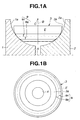
- Power roller 3 has traction surface 3a circumferentially extending and forming a convexly curved surface. Power roller 3 has a central connection hole 4 shown in Fig. 1B, through which power roller 3 is mounted to a support member, not shown.
- Power roller 3 is rotatable about axis B intersecting rotation axis A of disks 1 and 2 and swingable about swing center C, which is located on rotation axis B, to be inclined relative to disks 1 and 2.
- Power roller 3 is operated by a drive mechanism, not shown.
- Power roller 3 is contacted with input and output disks 1 and 2 at a predetermined pressure by pressure-apply mechanisms for applying load or force to disks 1 and 2 in a direction of rotation axis A and to power roller 3 in a direction of rotation axis B, respectively.
- Power roller 3 is in contact with input and output disks 1 and 2 via a traction oil film formed therebetween.
- At least one of input and output disks 1 and 2 and power roller 3 has a surface roughness on traction surface 1a, 2a and 3a thereof which varies in a direction of rotation axis A and B thereof.
- traction surface 3a of power roller 3 has a surface roughness varying in the direction of rotation axis B.
- traction surface 3a has a microstructure with irregularities at only contact region D shown in Figs. 1A and 1B, in which traction surface 3a is substantially in contact with traction surfaces 1a and 2a of disks 1 and 2.
- the irregularities of the microstructure is formed by recesses and projections alternately arranged.
- the recesses are in the form of dimples or grooves and varied in at least one of a depth and a density in the direction of rotation axis B.
- the density of the recesses means a ratio of a sum of areas of the recesses to unit area in contact region D of traction surface 3a of power roller 3.
- contact region D extends over an outer circumferential surface of power roller 3 in a concentric relation to rotation axis B with a predetermined width.
- Contact region D is separated into upper region D1 and lower region D2 by theoretical contact portion E explained later, in the direction of rotation axis B.
- the depth of the recesses is gradually increased from theoretical contact portion E toward at least one end of contact region D which are opposed to each other in the direction of rotation axis B, namely, along the swing direction of power roller 3.
- the depth of the recesses is gradually increased from theoretical contact portion E toward both the ends of contact region D within upper and lower regions D1 and D2.
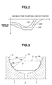
- Fig. 2 illustrates three examples 100, 200 and 300 showing a relationship between a distance from theoretical contact portion E and a depth of the recess within upper region D1 of contact region D.
- the depth of the recess is gradually increased.
- the depth of the recess is decreased again near the upper end of upper region D1 which is remotest from theoretical contact portion E. This is because the recess is to be disappeared toward outside of upper region D1.
- Traction surface 3a of power roller 3 is a convexly curved surface of a torus formed by rotating a circular arc having radius Rp of curvature about rotation axis B. That is, traction surface 3a of power roller 3 is determined by a length of radius Rp of curvature and a distance between a center of the curvature and rotation axis B.
- Each of traction surfaces 1a and 2a of input and output disks 1 and 2 is a concavely curved surface of a torus formed by rotating a circular arc having radius Rd of curvature about rotation axis A.
- Theoretical contact portion E is a position in which traction surface 3a of power roller 3 is inscribed in a sphere whose radius is equivalent to radius Rd of curvature of traction surfaces 1a and 2a of disks 1 and 2.
- theoretical contact portion E is a position in which a substantial center of a contact ellipse between traction surface 3a of power roller 3 and traction surfaces 1a and 2a of disks 1 and 2 is located.
- the contact ellipse is an elliptical contact area where traction surface 3a of power roller 3 is in contact with traction surfaces 1a and 2a of disks 1 and 2.
- Contact region D is determined by the contact ellipses continuously connected in a circumferential direction of power roller 3.
- Theoretical contact portion E therefore, is located in a substantial center of contact region D.
- the ratio of the width of contact region D along rotation axis B to the width of traction surface 3a along rotation axis B is in the range of approximately 1/10 to 1/3 relative.
- toroidal CVT is operative to transmit the rotation of input disk 1 to output disk 2 via power rollers 3.
- power rollers 3 are swung and inclined relative to disks 1 and 2 so that the contact between power rollers 3 and disks 1 and 2 shifts. This changes the ratio of the torque radius of input disk 1 to that of output disk 2 to thereby continuously change the gear ratio.
- the recesses of the microstructure are formed in contact region D of traction surface 3a of power roller 3 as explained above.
- the thickness of the traction oil film formed between traction surface 3a of power roller 3 and traction surfaces 1a and 2a of input and output disks 1 and 2 can be prevented from being excessively thickened within all speed ranges even under the operating condition of high-speed rolling.
- the thickness of the traction oil film can be kept suitable for maintaining high traction coefficient.
- the depth of the recesses formed in contact region D is reduced at the central portion of the contact ellipse which corresponds to theoretical contact portion E.
- the depth of the recesses is gradually increased toward the opposite ends of the contact ellipse which are opposed in the swing direction of power roller 3, namely, in the direction of rotation axis B, within upper and lower regions D1 and D2 of contact region D.
- the contact surface pressure on the central portion of the contact ellipse is high, the thickness of the traction oil film disposed at the central portion of the contact ellipse is prevented from excessively increasing in spite of the reduced depth of the recesses formed thereat.
- the toroidal CVT of the present invention can maintain high traction coefficient and suppress the peelings at the central portion of the contact ellipse and the wear at the opposite ends thereof to thereby assure sufficient durability.
- the recesses are formed only within contact region D of traction surface 3a of power roller 3, as a minimal area for the contact with traction surfaces 1a and 2a of disks 1 and 2. This can serve for saving the production time and cost. Further, the occurrence of cracks at large-diameter and small-diameter end portions of power roller 3 can be effectively restricted.
- the variation of the surface roughness of traction surface 3a of power roller 3 is not limited to the variation of the depth of the recesses of the microstructure in the direction of rotation axis B of power roller 3 as explained in the first embodiment.
- the density of the recesses of the microstructure of traction surface 3a of power roller 3, or both of the depth and the density thereof may be varied in the direction of rotation axis B.
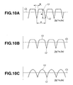
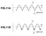
- Figs. 10A-12C there are shown examples of shapes of valleys 12 and ridges 13 appearing on an unfiltered primary profile curve of traction surface 3a of power roller 3 of the toroidal CVT of the present invention.
- the unfiltered primary profile curve is measured using a surface roughness tester.
- Valleys 12 and ridges 13 are alternately arranged and correspond to the recesses and the projections of the microstructure of traction surface 3a.
- the examples of shapes of ridges 13 located at a portion higher than center line CL of the profile curves include a generally trapezoidal shape shown in Fig. 10A, a generally trapezoidal shape with rounded corners shown in Fig. 10B, a generally elliptic arc or sinusoidal shape shown in Fig.
- ridges 13 also include a generally trapezoidal shape with chamfered corners shown in Fig. 12A, a generally crowning shape shown in Fig. 12B, and the one-sided crowning shape formed by lapping shown in Fig. 12C.
- a shape of bottoms of valleys 12 There are no limitations to a shape of bottoms of valleys 12, and the shape of bottoms thereof may have fine irregularities shown in Fig. 11B. These shapes serve for suppressing metal-to-metal contact caused at the mutual contact portion between traction surfaces 1a and 2a of disks 1 and 2 and traction surface 3a of power roller 3 and at the same time, for providing high traction coefficient.
- Width W is a length of the segment of center line CL which corresponds to valley 12. The segment is given by crossing center line CL with the unfiltered primary profile curve.
- Each of input and output disks 1 and 2 was formed from a workpiece made of JIS SCM435H steel. The workpiece was subjected to carbonitriding-quenching-tempering to have a Vickers hardness of Hv750, and then subjected to superfinishing to form traction surface 1a and 2a. Each disk 1 and 2 having traction surface 1a and 2a was thus formed. The unfiltered primary profile curve of traction surface 1a and 2a of disk 1 and 2 is shown in Fig. 13.
- Power roller 3 was formed from a workpiece made of JIS SCM435H steel. The workpiece was subjected to carbonitriding-quenching to have a Vickers hardness of Hv750. The workpiece was then subjected to ultra-precision cutting using a polycrystalline cubic boron nitride (c-BN) tool having a round end having an R 50 ⁇ m, to form circumferential grooves at equal intervals and projections between the grooves. The circumferential grooves were in the form of a spiral groove extending along the rotating direction of power roller 3. Subsequently, the projections were machined by tape lapping to form flat lands on the tops of the projections. Traction surface 3a was thus obtained.
- c-BN polycrystalline cubic boron nitride
- the unfiltered primary profile curve of traction surface 3a of power roller 3 is shown in Fig. 14.
- the shape of ridges located higher than center line CL of the unfiltered primary profile curve as explained in Figs. 10A-12C, is a generally trapezoidal shape with rounded corners.
- height difference H between the top of the ridge and the bottom of the valley is 2.4 ⁇ m.
- Pitch P of the valleys is 120 ⁇ m.
- Pitch P is used as a factor representing the density of the recesses.
- Width W of the valley namely, a length of the segment of center line CL which corresponds to the valley, is approximately 30-35 ⁇ m.
- the ratio of a sum of width W of the valleys to a reference length of center line CL is within a range of 25-29%.
- a radius of curvature of a top portion of the ridge of the unfiltered primary profile curve measured using the surface roughness tester which is set at equal longitudinal and lateral magnifications, is 10 mm.
- Arithmetical mean roughness Ra of the top portion of the ridge is approximately 0.005 ⁇ m.
- a performance test of the toroidal CVT using thus-produced disks 1 and 2 and power roller 3 was conducted.
- the maximum torque that can be transmitted without occurrence of gross slip between traction surfaces 1a, 2a and 3a during the operation was measured under the following condition. Oil temperature was 110°C, and input rotation number was 4000 rpm. Gear ratio was 1:1 at which the circumferential speed was 20 m/s.
- the loading force applied to power roller 3 was set at a fixed value. The test was carried out several times in which the loading force was set at different values.
- the test results were compared with those of the conventional CVTs using the disks and the power roller each having smooth traction surfaces which were formed by superfinishing.
- the maximum torque measured was approximately 1.05-1.3 times that of the conventional CVTs. The maximum torque is effective in improving the traction coefficient.
- traction surface 3a of power roller 3 had different depth and density of the recesses or the unfiltered primary profile curve thereof had different characteristics.
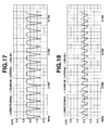
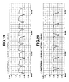
- Figs. 15-21 show the unfiltered primary profile curves of traction surfaces 3a of these examples, respectively.
- Each unfiltered primary profile curve includes alternately arranged valleys and ridges corresponding to the recesses and the projections of traction surface 3a.
- the ridges of the unfiltered primary profile curve have portions that are located higher than center line CL and have either one of the generally trapezoidal shape with rounded corners shown in Fig. 10B, the generally elliptic arc or sinusoidal shape shown in Fig. 10C, the generally triangular shape with a rounded apex shown in Fig.
- FIG. 11A the generally trapezoidal shape with chamfered corners shown in Fig. 12A, and a generally crowning shape shown in Fig. 12B.
- Height difference H between the top of the ridge and the bottom of the valley at the maximum recess-depth portion is within a range of 0.8-2.4 ⁇ m.
- Pitch P of the valleys is within a range of 40-150 ⁇ m.
- Width W of the valley is approximately 13-35 ⁇ m.
- the ratio of a sum of width W of the valleys to a reference length of center line CL is within a range of 15-40%.
- a radius of curvature of a top portion of the ridge of the unfiltered primary profile curve measured using the surface roughness tester which is set at equal longitudinal and lateral magnifications, is within a range of 0.8-170 mm.
- Arithmetical mean roughness Ra of the top portion of the ridge is approximately 0.005-0.02 ⁇ m.
- traction surface 3a of power roller 3 was produced by forming dimples having a diameter of approximately 2 ⁇ m by shot-peening and then flattening outer-most portions of the projections disposed between the dimples by lapping.
- traction surface 1a and 2a of each of input and output disks 1 and 2 varies in the direction of rotation axis A.
- traction surface 1a and 2a of each disk 1 and 2 has the microstructure with irregularities formed by recesses and projections.
- the recesses are in the form of dimples or a continuously extending circumferential groove.
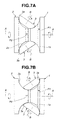
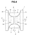
- the recesses formed on traction surface 1a of input disk 1 have the depth gradually increased from the reduced-diameter side of input disk 1 toward the increased-diameter side thereof as indicated by arrow F in Fig. 4B, namely, in the direction of rotation axis A.
- the recesses formed on traction surface 2a of output disk 2 have the depth gradually increased from the increased-diameter side of output disk 2 toward the reduced-diameter side thereof as indicated by arrow G in Fig. 4B, namely, in the direction of rotation axis A.
- Valleys and ridges of the unfiltered primary profile curve of traction surface 1a and 2a are the same in shape as either one of Figs. 10A-12C.
- traction surface 1a of input disk 1 has the recesses whose depth is gradually increased toward the increased-diameter side of input disk 1 as described above. With the arrangement of the recesses, the traction oil film disposed at the mutual contact portion between power roller 3 and the increased-diameter side of input disk 1 can be prevented from being increased in thickness.
- the mutual contact portion between output disk 2 and power roller 3 is moved from the increased-diameter side of output disk 2 to the reduced-diameter side thereof.
- the circumferential speed of output disk 2 at the mutual contact portion is substantially equivalent to the circumferential speed of input disk 1 at the mutual contact portion as indicated by arrows in Figs. 4A and 4C. Therefore, as the mutual contact portion between output disk 2 and power roller 3 is moved toward the reduced-diameter side of output disk 2, the circumferential speed of output disk 2 at the mutual contact portion becomes higher.
- the recesses of traction surface 2a of output disk 2 have the depth gradually increased toward the reduced-diameter side. With the arrangement of the recesses, the traction oil film disposed at the mutual contact portion between power roller 3 and the reduced-diameter side of output disk 2 can be prevented from being thickened.
- the traction oil film formed between input and output disks 1 and 2 and power roller 3, i.e., at the mutual contact portion between disks 1 and 2 and power roller 3, can be restrained from being increased in thickness when the circumferential speed of the mutual contact portion becomes higher in HIGH speed range.
- the traction oil film therefore, can have a suitable thickness for effectively performing the torque transmission between input and output disks 1 and 2 and power roller 3. This serves for assuring high traction coefficient of input and output disks 1 and 2.
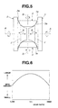
- traction surface 1a and 2a of each of input and output disks 1 and 2 includes a central contact region as simply indicated by broken line J, with respect to traction surface 3a of power roller 3.
- a gear ratio between input and output disks 1 and 2 is within a range of 1:1 to 1.3:1.
- a reduced-diameter side contact portion and an increased-side contact portion are disposed adjacent to central contact region J and extend in opposite directions as indicated by arrows K in Fig. 5.
- Central contact region J, the reduced-diameter side contact portion and the increased-side contact portion have a microstructure with irregularities formed by recesses and projections.
- the recesses have the depth that is gradually reduced from central contact region J into both the reduced-diameter side contact portion and the increased-diameter side contact portion in the opposite directions K in Fig. 5 along rotation axis A.
- Fig. 6 shows a relationship between a gear ratio between input and output disks 1 and 2 and an amount of spin occurring between traction contact portions of disks 1 and 2 and power roller 3.
- the gear ratio is approximately 1:1
- the spin amount becomes maximum.
- the maximum spin amount causes heat at the traction contact portions of disks 1 and 2 and power roller 3, whereby the temperature of the traction oil disposed at the traction contact portions rises to decrease the viscosity of the traction oil.
- the conventional toroidal CVTs there is a tendency to deteriorate the traction coefficient due to the decrease of the traction oil viscosity.
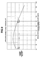
- Fig. 9 shows a characteristic curve of a loading force for power rollers which is required for transmitting torque without loss, relative to a gear ratio between input and output disks of the toroidal CVTs.
- the gear ratio is represented by an inclination or swing angle of the power roller.
- the required loading force becomes maximum.
- the relationship between the loading force and the gear ratio is described in "Toroidal CVT", p. 29-30, authored by Hirohisa Tanaka and published from CORONA PUBLISHING CO., LTD.
- a loading cam creates the loading force in proportion to the torque, the torque transmission performance substantially decreases at the gear ratio of approximately 1.3:1. Therefore, higher traction coefficient is required at the gear ratio of approximately 1.3:1 for less deterioration of the torque transmission performance.
- traction surface 1a and 2a of each of input and output disks 1 and 2 includes the recesses that are the maximum in depth in central contact region J relative to power roller 3 where the gear ratio between input and output disks 1 and 2 is within the range of 1:1 to 1.3:1.
- the depth of the recesses is reduced in the reduced-diameter side contact portion and increased-diameter side contact portion of traction surface 1a and 2a.
- the depth of the recesses is the maximum in central contact region J where the traction oil viscosity is decreased due to the heat generation caused by the large amount of spin and where the torque transmission performance is lowered due to the insufficient loading force created by the loading cam.
- the traction oil film disposed on central contact region J can have a proper thickness to increase a shear rate, whereby the traction coefficient can be prevented from being lowered due to the decrease of the traction oil viscosity.
- high traction coefficient of input and output disks 1 and 2 can be assured, resulting in less deterioration of the torque transmission performance.
- a half-toroidal CVT in which the power roller has a half-vertical angle of 60 degrees is used. If the half-vertical angle is varied, the contact region of the traction surface of each disk relative to the traction surface of the power roller will be displaced and therefore the depth of the recesses must be adjusted.
- FIG. 7A and 7B a fourth embodiment of the toroidal CVT of the invention is explained.
- traction surfaces 1a and 2a of input and output disks 1 and 2 include increased-diameter side contact portion P1 and reduced-diameter side contact portion P2, respectively.
- Increased-diameter side contact portion P1 is located on the increased-diameter side of input disk 1 and reduced-diameter side contact portion P2 is located on the reduced-diameter side of output disk 2.
- Increased-diameter side contact portion P1 and reduced-diameter side contact portion P2 are disposed within contact regions of traction surfaces 1a and 2a, respectively, which are brought into contact with traction surface 3a of power roller 3.
- Increased-diameter side contact portion P1 and reduced-diameter side contact portion P2 have a microstructure with irregularities formed by recesses and projections.
- the circumferential speed of input disk 1 becomes higher on the increased-diameter side and the circumferential speed of output disk 2 becomes higher on the reduced-diameter side.
- the higher circumferential speed tends to cause the thickness of the traction oil film to be increased.
- the microstructure with irregularities is arranged within increased-diameter side contact portion P1 and reduced-diameter side contact portion P2 of traction surfaces 1a and 2a of input and output disks 1 and 2, on which the circumferential speed becomes higher.
- the traction oil film disposed between the increased-diameter side of input disk 1 and power roller 3 and between the reduced-diameter side of output disk 2 and power roller 3 can be restrained from being thickened due to the higher circumferential speed on the respective increased-diameter side of input disk 1 and reduced-diameter side of output disk 2.
- a region required to be formed with the recesses of the microstructure can be limited to thereby save the production time, work and cost.
- the occurrence of cracks due to formation of the recesses can be suppressed in portions outside of increased-diameter side contact portion P1 and reduced-diameter side contact portion P2, specially, in the opposite end portions on the increased-diameter and reduced-diameter sides of disk 1 and 2. As a result, the durability of disks 1 and 2 can be improved.
- traction surfaces 1a and 2a of input and output disks 1 and 2 include contact regions P3 and P4 relative to traction surface 3a of power roller 3, respectively.
- Contact regions P3 and P4 are brought into contact with traction surface 3a during the swing operation of power roller 3.
- a gear ratio between input and output disks 1 and 2 is within a range of 1:1 to 1.3:1.
- Each of contact regions P3 and P4 has a microstructure with irregularities formed by recesses and projections.
- the recesses of the microstructure are formed within contact regions P3 and P4 where the gear ratio between disks 1 and 2 is within the range of 1:1 to 1.3:1, the thickness of the traction oil film disposed at contact regions P3 and P4 can be adequately adjusted in spite of the maximum spin amount occurring therein as discussed above using Fig. 6. As a result, the traction coefficient of each of input and output disks 1 and 2 can be prevented from being deteriorated.
- the torque transmission performance can be restrained from being deteriorated due to the decrease of the loading force which is caused at the gear ratio of approximately 1.3:1 as explained above using Fig. 9.
- the recesses of the microstructure may be formed in only a portion of contact regions P3 and P4 which will most adversely affect the traction coefficient and the torque transmission performance.
- the production time, work and cost can be saved. The occurrence of cracks due to formation of the recesses can be suppressed in portions outside of contact regions P3 and P4, whereby the durability of disks 1 and 2 can be improved.
- the recesses of the microstructure are not limited to those as described in the embodiments, and may be varied in depth, density or both of depth and density. Even in such the case, the same effects as those of the embodiments can be obtained. Further, the recesses can be formed on traction surface 1a and 2a of either one of input and output disks 1 and 2, or any combination of the recesses of the above-described embodiments may be formed on traction surfaces 1a and 2a of disks 1 and 2. Furthermore, the recesses may be varied in shape, depth or density so as to avoid the deterioration of durability of input and output disks and power rollers which is caused by metal-to-metal contact, on the basis of operating conditions of the toroidal CVT.
- the recesses also may be varied so as to stably maintain so-called oil film thickness ratio in relation to surface roughness, depending on the temperature condition and gear ratio that influence the traction coefficient.
- the surface roughness may be set so as to assure the high traction coefficient as explained in the above-described embodiments, over under high temperature condition which causes large deterioration of the traction coefficient.
- microstructure with irregularities can be formed on both of traction surfaces 1a and 2a of input and output disks 1 and 2 and traction surface 3a of power roller 3 in the following manner.
- the thickness of the traction oil film between input and output disks 1 and 2 and power roller 3 can be optimally adjusted on the basis of both of the contact surface pressure at the contact ellipse of power roller 3 relative to disks 1 and 2 and the circumferential speed of disks 1 and 2. Owing to the proper adjustment of the thickness of the traction oil film, the durability can be assured and the high traction coefficient can be maintained.
- the microstructure with irregularities can be formed on traction surfaces 1a and 2a of input and output disks 1 and 2 as described in the third embodiment, and on traction surface 3a of power roller 3 as described in the second embodiment.
- the thickness of the traction oil film can be optimally adjusted according to the contact surface pressure at the contact ellipse of power roller 3 relative to disks 1 and 2, as well as the spin amount at the mutual contact portion between disks 1 and 2 and power roller 3 and the loading force for power roller 3, the latter two of which are concerned with the gear ratio between disks 1 and 2.
- recesses can be formed on a part of traction surface 3a of power roller 3 which is always in contact with disks 1 and 2, for adjustment of the thickness of the traction oil film on the basis of the general operating condition, and at the same time, be formed on traction surfaces 1a and 2a of disks 1 and 2 for fine adjustment of the thickness of the traction oil film.
- the recesses since the recesses are formed on both sides of the mutual contact portion between power roller 3 and disks 1 and 2, the recesses may be reduced in depth. Therefore, the occurrence of cracks due to formation of the recesses can be effectively restricted.
Landscapes
- Engineering & Computer Science (AREA)
- General Engineering & Computer Science (AREA)
- Mechanical Engineering (AREA)
- Friction Gearing (AREA)
Abstract
Description
Claims (18)
- A toroidal continuously variable transmission, comprising:an input disk (1);an output disk (2), the input and output disks (1, 2) having a common first rotation axis (A) about which the input and output disks (1, 2) are rotatable; anda power roller (3) swingably interposed between the input and output disks (1, 2) and having a second rotation axis (B) intersecting the first rotation axis (A), about which the power roller (3) is rotatable,the input and output disks (1, 2) and the power roller (3) having traction surfaces (1a, 2a, 3a) cooperating with each other to transmit rotation between the input and output disks (1, 2) and the power roller (3),at least one of the input and output disks (1, 2) and the power roller (3) having a surface roughness on the traction surface (1a, 2a, 3a) thereof which varies in a direction of the rotation axis (A, B) thereof.
- The toroidal continuously variable transmission as claimed in claim 1, wherein the at least one of the traction surfaces (1a, 2a, 3a) comprises a microstructure with irregularities at only a contact region (D; P1, P2; P3, P4) thereof.
- The toroidal continuously variable transmission as claimed in claim 1 or 2, wherein the traction surface (3a) of the power roller (3) comprises a microstructure with irregularities formed by recesses and projections at a region (D) of the traction surface (3a) of the power roller (3) which has opposite ends in the direction of the rotation axis (B), the recesses being varied such that at least one of a depth and a density thereof is increased from a theoretical contact portion (E) between the power roller and the input and output disks (1, 2) toward at least one of the opposite ends of the region (D).
- The toroidal continuously variable transmission as claimed in any one of claims 1-3, wherein the traction surface (1a) of the input disk (1) comprises a microstructure with irregularities formed by recesses and projections, the input disk (1) comprising a reduced-diameter side and an increased-diameter side, the recesses being varied such that at least one of a depth and a density thereof is increased from the reduced-diameter side of the input disk (1) toward the increased-diameter side of the input disk (1).
- The toroidal continuously variable transmission as claimed in any one of claims 1-4, wherein the traction surface (2a) of the output disk (2) comprises a microstructure with irregularities formed by recesses and projections, the output disk (2) comprising a reduced-diameter side and an increased-diameter side, the recesses being varied such that at least one of a depth and a density thereof is increased from the increased-diameter side of the output disk (2) toward the reduced-diameter side of the output disk (2).
- The toroidal continuously variable transmission as claimed in any one of claims 1-3, wherein the traction surface (1a, 2a) of each of the input and output disks (1, 2) comprises a microstructure with irregularities formed by recesses and projections, a reduced-diameter side contact portion, an increased-diameter side contact portion and a contact region (J) between the reduced-diameter side contact portion and the increased-diameter side contact portion in which a gear ratio between the input and output disks (1, 2) is within a range of 1:1 to 1.3:1, the recesses being varied such that at least one of a depth and a density is a maximum in the contact region (J) and is reduced into the reduced-diameter side contact portion and the increased-diameter side contact portion.
- The toroidal continuously variable transmission as claimed in any one of claims 1-3, wherein the traction surface (1a) of the input disk (1) comprises a contact region (P1) brought into contact with the traction surface (3a) of the power roller (3), the contact region (P1) comprising an increased-diameter side contact portion on which a microstructure with irregularities is disposed.
- The toroidal continuously variable transmission as claimed in any one of claims 1-3 and 7, wherein the traction surface (2a) of the output disk (2) comprises a contact region (P2) brought into contact with the traction surface (3a) of the power roller (3), the contact region (P2) comprising a reduced-diameter side contact portion on which a microstructure with irregularities is disposed.
- The toroidal continuously variable transmission as claimed in any one of claims 1-3, wherein the traction surface (1a, 2a) of each of the input and output disks (1, 2) comprises a contact region (P3, P4) relative to the traction surface (3a) of the power roller (3) in which a gear ratio between the input and output disks (1, 2) is within a range of 1:1 to 1.3:1, and a microstructure with irregularities within the contact region (P3, P4).
- The toroidal continuously variable transmission as claimed in any one of claims 1-9, wherein the at least one of the traction surfaces (1a, 2a, 3a) comprises a microstructure with irregularities, the microstructure being represented by an unfiltered primary profile curve including alternately arranged valleys (12) and ridges (13).
- The toroidal continuously variable transmission as claimed in claim 10, wherein the unfiltered primary profile curve is measured using a surface roughness tester, each of the ridges (13) of the unfiltered primary profile curve including an upper portion located higher than a center line (CL) with respect to the unfiltered primary profile curve, the upper portion having either one shape selected from a generally trapezoidal shape, a generally trapezoidal shape with rounded corners, a generally trapezoidal shape with chamfered corners, a generally crowning shape, a generally elliptic arc shape, a generally sinusoidal shape and a generally triangular shape with a rounded apex.
- The toroidal continuously variable transmission as claimed in claim 10 or 11, wherein the microstructure comprises alternately arranged recesses and projections forming the irregularities, the microstructure comprising a maximum recess-depth portion where the recesses have a maximum depth, a height difference (H) between a top of each ridge (13) and a bottom of each valley (12) in the maximum recess-depth portion being within a range of 0.7-2.5 µm.
- The toroidal continuously variable transmission as claimed in any one of claims 10-12, wherein the microstructure comprises a maximum recess-density portion where the recesses have a maximum density, in which a ratio of a total length of segments of the center line (CL) which correspond to the valleys (12) of the unfiltered primary profile curve, to a reference length of the center line (CL) is within a range of 15-45%.
- The toroidal continuously variable transmission as claimed in any one of claims 10-13, wherein a pitch between the valleys (12) adjacent to each other is within a range of 40-150 µm.
- The toroidal continuously variable transmission as claimed in any one of claims 10-14, wherein the unfiltered primary profile curve is measured by a surface roughness tester set at equal longitudinal and lateral magnifications, the ridges (13) of the unfiltered primary profile curve comprising a top portion having a radius of curvature of 0.8-170 mm.
- The toroidal continuously variable transmission as claimed in any one of claims 10-15, wherein the ridge (13) of the unfiltered primary profile curve comprises a top portion having an arithmetical mean roughness Ra of 0.02 µm or less.
- The toroidal continuously variable transmission as claimed in any one of claims 12-16, wherein the recesses are formed by a continuous groove spirally extending in substantially parallel to the rotating direction of the at least one of the input and output disks (1, 2) and the power roller (3).
- The toroidal continuously variable transmission as claimed in any one of claims 12-16, wherein the recesses are a plurality of dimples spaced from each other.
Applications Claiming Priority (6)
| Application Number | Priority Date | Filing Date | Title |
|---|---|---|---|
| JP2000196684 | 2000-06-29 | ||
| JP2000196684 | 2000-06-29 | ||
| JP2000210078 | 2000-07-11 | ||
| JP2000210078 | 2000-07-11 | ||
| JP2001062696 | 2001-03-06 | ||
| JP2001062696A JP3736619B2 (en) | 2000-06-29 | 2001-03-06 | Toroidal continuously variable transmission |
Publications (3)
| Publication Number | Publication Date |
|---|---|
| EP1167819A2 true EP1167819A2 (en) | 2002-01-02 |
| EP1167819A3 EP1167819A3 (en) | 2007-05-23 |
| EP1167819B1 EP1167819B1 (en) | 2008-12-10 |
Family
ID=27343898
Family Applications (1)
| Application Number | Title | Priority Date | Filing Date |
|---|---|---|---|
| EP01115841A Expired - Lifetime EP1167819B1 (en) | 2000-06-29 | 2001-06-28 | Toroidal continuously variable transmission |
Country Status (4)
| Country | Link |
|---|---|
| US (1) | US6527667B2 (en) |
| EP (1) | EP1167819B1 (en) |
| JP (1) | JP3736619B2 (en) |
| DE (1) | DE60136887D1 (en) |
Cited By (4)
| Publication number | Priority date | Publication date | Assignee | Title |
|---|---|---|---|---|
| WO2008034438A1 (en) * | 2006-09-22 | 2008-03-27 | Ulrich Rohs | Bevel friction ring gear mechanism |
| US7465249B2 (en) | 2004-10-26 | 2008-12-16 | Nsk Ltd. | Toroidal type continuously variable transmission |
| EP1235002A3 (en) * | 2001-02-21 | 2009-04-22 | Nissan Motor Company, Limited | Traction drive rotary assembly |
| DE102008026862B4 (en) * | 2007-06-06 | 2013-02-21 | Nsk Ltd. | Stepless toroidal transmission |
Families Citing this family (12)
| Publication number | Priority date | Publication date | Assignee | Title |
|---|---|---|---|---|
| JP3664058B2 (en) * | 1999-09-07 | 2005-06-22 | 日産自動車株式会社 | Rolling element for traction drive and manufacturing method thereof |
| DE10228344B4 (en) * | 2002-06-25 | 2007-02-08 | Infineon Technologies Ag | Process for the production of microstructures and arrangement of microstructures |
| JP4196636B2 (en) | 2002-10-17 | 2008-12-17 | 日産自動車株式会社 | Method for manufacturing rolling element for traction drive |
| JP2004138165A (en) * | 2002-10-18 | 2004-05-13 | Nissan Motor Co Ltd | Traction drive disk and method of manufacturing the same |
| US20060019796A1 (en) * | 2004-03-31 | 2006-01-26 | Brooks Todd D | Toroidal continuously variable transmission with offset rollers |
| JP4623365B2 (en) * | 2004-10-26 | 2011-02-02 | 日本精工株式会社 | Toroidal continuously variable transmission |
| JP2006125444A (en) * | 2004-10-26 | 2006-05-18 | Nsk Ltd | Toroidal continuously variable transmission |
| TWI344417B (en) * | 2009-02-06 | 2011-07-01 | Primax Electronics Ltd | Continuous variable speed-changing transmission mechanism for a sheet laminating appatatus |
| US9458917B2 (en) * | 2011-04-18 | 2016-10-04 | Transmission Cvtcorp Inc. | Continuously variable transmission provided with a roller parking zone |
| JP2012225383A (en) * | 2011-04-18 | 2012-11-15 | Nsk Ltd | Toroidal continuously variable transmission |
| JP2012233504A (en) * | 2011-04-28 | 2012-11-29 | Nsk Ltd | Toroidal continuously variable transmission |
| WO2017175255A1 (en) * | 2016-04-06 | 2017-10-12 | 川崎重工業株式会社 | Toroidal continuously variable transmission |
Family Cites Families (6)
| Publication number | Priority date | Publication date | Assignee | Title |
|---|---|---|---|---|
| GB784296A (en) * | 1953-06-23 | 1957-10-09 | Zenas Virgil Weisel | Improvements in or relating to friction gear transmission |
| JP3718973B2 (en) | 1997-11-14 | 2005-11-24 | 日本精工株式会社 | Toroidal continuously variable transmission |
| JP3664058B2 (en) * | 1999-09-07 | 2005-06-22 | 日産自動車株式会社 | Rolling element for traction drive and manufacturing method thereof |
| JP3630297B2 (en) * | 2000-03-23 | 2005-03-16 | 日産自動車株式会社 | Toroidal continuously variable transmission for automobiles |
| JP2003343675A (en) * | 2002-05-30 | 2003-12-03 | Nissan Motor Co Ltd | Rolling element for traction drive and toroidal continuously variable transmission |
| JP4196636B2 (en) * | 2002-10-17 | 2008-12-17 | 日産自動車株式会社 | Method for manufacturing rolling element for traction drive |
-
2001
- 2001-03-06 JP JP2001062696A patent/JP3736619B2/en not_active Expired - Fee Related
- 2001-06-28 EP EP01115841A patent/EP1167819B1/en not_active Expired - Lifetime
- 2001-06-28 DE DE60136887T patent/DE60136887D1/en not_active Expired - Lifetime
- 2001-06-29 US US09/893,451 patent/US6527667B2/en not_active Expired - Lifetime
Cited By (7)
| Publication number | Priority date | Publication date | Assignee | Title |
|---|---|---|---|---|
| EP1235002A3 (en) * | 2001-02-21 | 2009-04-22 | Nissan Motor Company, Limited | Traction drive rotary assembly |
| US7465249B2 (en) | 2004-10-26 | 2008-12-16 | Nsk Ltd. | Toroidal type continuously variable transmission |
| WO2008034438A1 (en) * | 2006-09-22 | 2008-03-27 | Ulrich Rohs | Bevel friction ring gear mechanism |
| EP2434182A1 (en) * | 2006-09-22 | 2012-03-28 | Ulrich Rohs | Spherical friction ring gearbox |
| US8187142B2 (en) | 2006-09-22 | 2012-05-29 | Ulrich Rohs | Bevel friction ring gear mechanism |
| DE102008026862B4 (en) * | 2007-06-06 | 2013-02-21 | Nsk Ltd. | Stepless toroidal transmission |
| US9188206B2 (en) | 2007-06-06 | 2015-11-17 | Nsk Ltd. | Toroidal continuously variable transmission |
Also Published As
| Publication number | Publication date |
|---|---|
| US6527667B2 (en) | 2003-03-04 |
| DE60136887D1 (en) | 2009-01-22 |
| JP3736619B2 (en) | 2006-01-18 |
| US20020002098A1 (en) | 2002-01-03 |
| EP1167819B1 (en) | 2008-12-10 |
| EP1167819A3 (en) | 2007-05-23 |
| JP2002089644A (en) | 2002-03-27 |
Similar Documents
| Publication | Publication Date | Title |
|---|---|---|
| US6527667B2 (en) | Toroidal continuously variable transmission | |
| US6736036B2 (en) | Traction drive rotary assembly and process for producing rolling element thereof | |
| US8038559B2 (en) | Power transmission chain, method for manufacturing power transmission member of the power transmission chain, and power transmission device | |
| EP1136724B1 (en) | Toroidal-type continuously variable transmission for automobiles | |
| JP4210661B2 (en) | Belt type continuously variable transmission | |
| US6416433B1 (en) | Chain-belt transmission with continuously variable transmission ratio | |
| US6293887B1 (en) | Plate link chain for continuously variable transmission | |
| JP4323357B2 (en) | Pulley manufacturing method | |
| KR20090117987A (en) | CVT belts | |
| US20030050142A1 (en) | Belt for non-stage transmissions | |
| US5823911A (en) | Supports for power rollers for use in toroidal-type continuously variable transmissions | |
| CN1469057A (en) | Belts for CVTs | |
| EP2236857A1 (en) | Transmission | |
| EP1544502B1 (en) | Drive belt | |
| EP1235002B1 (en) | Traction drive rotary assembly | |
| JP5056591B2 (en) | Toroidal continuously variable transmission | |
| US8100789B2 (en) | Anti-slip sheaves for continuously variable transmissions | |
| WO2011076234A1 (en) | Drive belt for a transmission with convex pulley sheaves | |
| JP2003269547A (en) | Belt for continuously variable transmission | |
| EP1548325B1 (en) | Continuously variable transmission metal belt, process for producing metal ring. | |
| JP2003343675A (en) | Rolling element for traction drive and toroidal continuously variable transmission | |
| JPH07310796A (en) | Toroidal type continuously variable transmission | |
| JP2021110389A (en) | Belt type continuously variable transmission and its manufacturing method | |
| JP3748067B2 (en) | Rolling element for traction drive | |
| JP4839369B2 (en) | Drive belt for continuously variable transmission and method for producing transverse element for such drive belt |
Legal Events
| Date | Code | Title | Description |
|---|---|---|---|
| PUAI | Public reference made under article 153(3) epc to a published international application that has entered the european phase |
Free format text: ORIGINAL CODE: 0009012 |
|
| 17P | Request for examination filed |
Effective date: 20010628 |
|
| AK | Designated contracting states |
Kind code of ref document: A2 Designated state(s): AT BE CH CY DE DK ES FI FR GB GR IE IT LI LU MC NL PT SE TR |
|
| AX | Request for extension of the european patent |
Free format text: AL;LT;LV;MK;RO;SI |
|
| PUAL | Search report despatched |
Free format text: ORIGINAL CODE: 0009013 |
|
| AK | Designated contracting states |
Kind code of ref document: A3 Designated state(s): AT BE CH CY DE DK ES FI FR GB GR IE IT LI LU MC NL PT SE TR |
|
| AX | Request for extension of the european patent |
Extension state: AL LT LV MK RO SI |
|
| RIC1 | Information provided on ipc code assigned before grant |
Ipc: F16H 55/34 20060101ALI20070419BHEP Ipc: F16H 55/32 20060101ALI20070419BHEP Ipc: F16H 15/38 20060101AFI20011010BHEP |
|
| AKX | Designation fees paid |
Designated state(s): DE FR GB |
|
| 17Q | First examination report despatched |
Effective date: 20080111 |
|
| GRAP | Despatch of communication of intention to grant a patent |
Free format text: ORIGINAL CODE: EPIDOSNIGR1 |
|
| GRAS | Grant fee paid |
Free format text: ORIGINAL CODE: EPIDOSNIGR3 |
|
| GRAA | (expected) grant |
Free format text: ORIGINAL CODE: 0009210 |
|
| AK | Designated contracting states |
Kind code of ref document: B1 Designated state(s): DE FR GB |
|
| REG | Reference to a national code |
Ref country code: GB Ref legal event code: FG4D |
|
| REF | Corresponds to: |
Ref document number: 60136887 Country of ref document: DE Date of ref document: 20090122 Kind code of ref document: P |
|
| PLBE | No opposition filed within time limit |
Free format text: ORIGINAL CODE: 0009261 |
|
| STAA | Information on the status of an ep patent application or granted ep patent |
Free format text: STATUS: NO OPPOSITION FILED WITHIN TIME LIMIT |
|
| 26N | No opposition filed |
Effective date: 20090911 |
|
| REG | Reference to a national code |
Ref country code: FR Ref legal event code: PLFP Year of fee payment: 16 |
|
| REG | Reference to a national code |
Ref country code: FR Ref legal event code: PLFP Year of fee payment: 17 |
|
| PGFP | Annual fee paid to national office [announced via postgrant information from national office to epo] |
Ref country code: DE Payment date: 20170621 Year of fee payment: 17 |
|
| REG | Reference to a national code |
Ref country code: FR Ref legal event code: PLFP Year of fee payment: 18 |
|
| PGFP | Annual fee paid to national office [announced via postgrant information from national office to epo] |
Ref country code: FR Payment date: 20180511 Year of fee payment: 18 |
|
| PGFP | Annual fee paid to national office [announced via postgrant information from national office to epo] |
Ref country code: GB Payment date: 20180403 Year of fee payment: 18 |
|
| REG | Reference to a national code |
Ref country code: DE Ref legal event code: R119 Ref document number: 60136887 Country of ref document: DE |
|
| PG25 | Lapsed in a contracting state [announced via postgrant information from national office to epo] |
Ref country code: DE Free format text: LAPSE BECAUSE OF NON-PAYMENT OF DUE FEES Effective date: 20190101 |
|
| GBPC | Gb: european patent ceased through non-payment of renewal fee |
Effective date: 20190628 |
|
| PG25 | Lapsed in a contracting state [announced via postgrant information from national office to epo] |
Ref country code: GB Free format text: LAPSE BECAUSE OF NON-PAYMENT OF DUE FEES Effective date: 20190628 |
|
| PG25 | Lapsed in a contracting state [announced via postgrant information from national office to epo] |
Ref country code: FR Free format text: LAPSE BECAUSE OF NON-PAYMENT OF DUE FEES Effective date: 20190630 |