EP1167764A2 - Variable displacement swash plate compressor - Google Patents
Variable displacement swash plate compressor Download PDFInfo
- Publication number
- EP1167764A2 EP1167764A2 EP01115485A EP01115485A EP1167764A2 EP 1167764 A2 EP1167764 A2 EP 1167764A2 EP 01115485 A EP01115485 A EP 01115485A EP 01115485 A EP01115485 A EP 01115485A EP 1167764 A2 EP1167764 A2 EP 1167764A2
- Authority
- EP
- European Patent Office
- Prior art keywords
- drive shaft
- region
- restricting member
- plate
- variable displacement
- Prior art date
- Legal status (The legal status is an assumption and is not a legal conclusion. Google has not performed a legal analysis and makes no representation as to the accuracy of the status listed.)
- Withdrawn
Links
Images


Classifications
-
- F—MECHANICAL ENGINEERING; LIGHTING; HEATING; WEAPONS; BLASTING
- F04—POSITIVE - DISPLACEMENT MACHINES FOR LIQUIDS; PUMPS FOR LIQUIDS OR ELASTIC FLUIDS
- F04B—POSITIVE-DISPLACEMENT MACHINES FOR LIQUIDS; PUMPS
- F04B27/00—Multi-cylinder pumps specially adapted for elastic fluids and characterised by number or arrangement of cylinders
- F04B27/08—Multi-cylinder pumps specially adapted for elastic fluids and characterised by number or arrangement of cylinders having cylinders coaxial with, or parallel or inclined to, main shaft axis
- F04B27/14—Control
- F04B27/16—Control of pumps with stationary cylinders
- F04B27/18—Control of pumps with stationary cylinders by varying the relative positions of a swash plate and a cylinder block
- F04B27/1804—Controlled by crankcase pressure
Definitions
- the present invention relates to a variable displacement compressor having single-headed pistons, which is used, for example, in a vehicular air conditioning system.
- a variable displacement swash plate clutch compressor shown in Fig. 8 has a solenoid clutch 101, which can interrupt power transmission from a vehicular engine Eg.
- the compressor also has a displacement control mechanism, which can reduce the displacement so that the solenoid clutch is not be turned on and off frequently when the cooling load is low.
- the displacement control mechanism has a swash plate 103 connected to pistons 102 through shoes 102a.
- a rotary support 105 is fixed to a drive shaft 104.
- the swash plate 103 is connected to the rotary support 105 through a hinge mechanism 106.
- the swash plate 103 is housed in the crank chamber 107.
- the differential pressure between the crank chamber 107 and the cylinder bores 18 varies to change the inclination angle of the swash plate 103.
- the stroke of each piston 102 is changed to change the displacement.
- the inclination angle of the swash plate 103 is reduced, which reduces the compressor displacement.
- the swash plate 103 indicated by the broken double-dashed line is at the minimum inclination position, where it abuts against a regulating ring 109 attached to the drive shaft 104.
- the piston 102, the swash plate 103, the hinge mechanism 106, the rotary support 105 and the drive shaft 104 transmit force to the internal wall surface of a housing 110 (leftward in Fig. 8) through a thrust bearing 111 due to the compression load on the piston 102.
- the internal pressure of the crank chamber 107 remains high so that the compressor can be started from the minimum displacement state, at which the load torque is minimized, even if the solenoid clutch is turned on soon after it is turned off. Further, control of the compressor displacement is performed to minimize the displacement, regardless of the cooling load, to reduce load of the engine Eg during rapid acceleration of the vehicle.
- the swash plate 103 When the internal pressure of the crank chamber 107 is increased rapidly to minimize the displacement, the swash plate 103 may be pressed against the regulating ring 109 with excessive force, or the rotary support 105 may be pulled strongly to the rear side of the compressor through the hinge mechanism 106. Thus, the drive shaft 104 is caused to slide or shift backward (rightward in Fig. 8) along the axis L.
- the piston 102 may impinge upon the valve plate 112 when reaching the top dead center position. This impingement causes vibrations and noise and may damage the pistons 102 or the valve plate 112.
- an armature 101a of the solenoid clutch 101 moves toward a rotor 101b to eliminate a clearance between the armature 101a and the rotor 101b or to bring the armature 101a into contact with the rotor 101b, which causes rattling or vibration and unnecessary power transmission.
- a spring 113 is located between the housing 110 and the drive shaft 104.
- the spring 113 urges the drive shaft 104 axially forward.
- Japanese Unexamined Patent Publication No. Hei 11-62824 discloses a compressor having a restricting member for restricting axial shifting of the drive shaft.
- the restricting member is located in a hole in which the rear end of the drive shaft is fitted.
- the hole communicates with a suction chamber through a space.
- a sealing member which prevents communication between a crank chamber and the space through the hole is applied around the rear end of the drive shaft.
- the thrust bearing 111 receives a great load from the spring 113, which reduces the life of the thrust bearing 111 and increases the power loss of the compressor at the thrust bearing 111.
- the increased power loss adversely affects the fuel consumption rate of the engine Eg that drives the compressor.
- a sealing member is located in the hole in which the rear end of a drive shaft is supported.
- the sealing member prevents entry of refrigerant into the hole. Therefore, lubricant cannot be supplied fully to the radial bearing, which shortens the life of the bearing.
- the present invention provides a variable displacement compressor.
- the compressor comprises a housing having a suction chamber and a discharge chamber.
- a crank chamber is defined in the housing.
- a drive shaft has a front end and a rear end. The shaft is supported in the housing so that the front end protrudes from the housing.
- a cylinder block forms part of the housing. Cylinder bores are defined in the cylinder block.
- a valve plate assembly includes a suction port, a suction valve, a discharge port and a discharge valve for each cylinder bore. Single-headed pistons are housed in the cylinder bores, respectively.
- a drive plate is housed in the crank chamber and is connected to the pistons to convert rotation of the drive shaft into reciprocating motion of the pistons.
- the drive plate rotates integrally with the drive shaft.
- a control mechanism controls inclination of the drive plate by controlling the pressure of the crank chamber to change the volume of a refrigerant discharged from each cylinder bore into the discharge chamber.
- a radial bearing supports the rear end of the drive shaft. The refrigerant flows through the radial bearing.
- a holding bore houses the rear end of the drive shaft and the radial bearing. The holding bore is connected to a holding space. The holding space is defined by the valve plate assembly.
- a passage connects the holding space and the suction chamber.
- a restricting member is located in the holding space. The restricting member restricts axial movement of the drive shaft and divides the holding space into a first region and a second region. The first region and the second region communicate with each other.
- a clearance is formed between the drive shaft and the restricting member or between the restricting member and the valve plate assembly in a normal compressing operation. The clearance disappears when the pressure of the crank chamber is increased rapidly by the control mechanism.
- the present invention also provides a variable displacement compressor.
- the compressor comprises a housing having a suction chamber and a discharge chamber.
- a crank chamber is defined in the housing.
- a drive shaft has a front end and a rear end. The shaft is supported in the housing so that the front end protrudes from the housing.
- a cylinder block forms part of the housing. Cylinder bores are defined in the cylinder block.
- a valve plate assembly includes a suction port, a suction valve, a discharge port and a discharge valve for each cylinder bore. Single-headed pistons are housed in the cylinder bores, respectively.
- a drive plate is housed in the crank chamber and is connected to the pistons to convert rotation of the drive shaft into reciprocating motion of the pistons. The drive plate rotates integrally with the drive shaft.
- a control mechanism controls inclination of the drive plate by controlling the pressure of the crank chamber to change the volume of a refrigerant discharged from each cylinder bore into the discharge chamber.
- a radial bearing supports the rear end of the drive shaft. The refrigerant flows through the radial bearing.
- a holding bore houses the rear end of the drive shaft and the radial bearing. The holding bore is connected to a holding space. The holding space is defined by the valve plate assembly. The holding space is connected to the suction chamber.
- Means for restricting restricts axial movement of the drive shaft. The restricting means are located in the holding space and divides the holding space into a first region and a second region.
- a clearance is formed between the drive shaft and the restricting means or between the restricting means and the valve plate assembly in a normal compressing operation. The clearance disappears when the pressure of the crank chamber is increased rapidly by the control mechanism.
- a passage connects the first region to the second region.
- the present invention also provides a variable displacement compressor.
- the compressor comprises a housing having a suction chamber and a discharge chamber.
- a crank chamber is defined in the housing.
- a drive shaft has a front end and a rear end. The shaft is supported in the housing so that the front end protrudes from the housing.
- a cylinder block forms part of the housing. Cylinder bores are defined in the cylinder block.
- a valve plate assembly includes a suction port, a suction valve, a discharge port and a discharge valve for each cylinder bore. Single-headed pistons are housed in the cylinder bores, respectively.
- a drive plate is housed in the crank chamber and is connected to the pistons to convert rotation of the drive shaft into reciprocating motion of the pistons. The drive plate rotates integrally with the drive shaft.
- a control mechanism controls inclination of the drive plate by controlling the pressure of the crank chamber to change the volume of a refrigerant discharged from each cylinder bore into the discharge chamber.
- a radial bearing supports the rear end of the drive shaft. The refrigerant flows through the radial bearing.
- a holding bore houses the rear end of the drive shaft and the radial bearing. The holding bore is connected to a holding space. The holding space is defined by the valve plate assembly.
- a passage connects the holding space and the suction chamber.
- a cylindrical body is located in the holding space. One end of the cylindrical body is fixed to the drive shaft, and the other end of the cylindrical body abuts against the valve plate assembly. The cylindrical body restricts axial movement of the drive shaft and divides the holding space into a first region and a second region.
- the cylindrical body has a hole to connect the first region to the second region.
- a clearance is formed between the drive shaft and the cylindrical body or between the cylindrical body and the valve plate assembly in a normal compressing operation. The clearance disappears when the internal pressure of the crank chamber is increased rapidly by the control mechanism.
- variable displacement compressor according to the first embodiment of the present invention is part of a vehicular air conditioning system and is described below referring to Figs. 1 and 2(b).
- a front housing member 11 is connected to the front end of a cylinder block 12.
- a rear housing member 13 is connected to the rear end of the cylinder block 12 through a valve plate assembly 14.
- the front housing member 11, the cylinder block 12 and the rear housing member 13 are fastened together with through-bolts (not shown).
- the front housing member 11, the cylinder block 12 and the rear housing member 13 form a housing of the compressor.
- the left side and the right side in Fig. 1 correspond to the front end and the rear end, respectively.
- the valve plate assembly 14 includes a main plate 14a, a first sub plate 14b, a second sub plate 14c and a retainer plate 14d.
- the first sub plate 14b and the second sub plate 14c are superposed on the front side and on the rear side of the main plate 14a, respectively.
- the retainer plate 14d is superposed on the rear side of the second sub plate 14c.
- the first sub plate 14b of the valve plate assembly 14 is connected to the cylinder block 12.
- a crank chamber 15 is defined between the front housing member 11 and the cylinder block 12.
- a drive shaft 16 passes through the crank chamber 15.
- the drive shaft 16 is supported between the front housing member 11 and the cylinder block 12, and the front end of the drive shaft 16 extends from the housing.
- the front end of the drive shaft 16 is supported in the front housing member 11 by a first radial bearing 17.
- a holding bore 18 is defined substantially at the center of the cylinder block 12.
- the rear end of the drive shaft 16 is supported by a second radial bearing 19 located in the holding bore 18.
- a shaft sealing device 20 is applied around the front end of the drive shaft 16. The device 20 prevents leakage of refrigerant.
- a plurality of cylinder bores 12a (only one cylinder bore is shown in Fig. 1) are defined in the cylinder block 12.
- the cylinder bores 12a are defined at equiangular intervals around the axis L of the drive shaft 16.
- Single-headed pistons 21 are housed in the cylinder bores 12a. Openings of each cylinder bore 12a are closed by the valve plate assembly 14 and the corresponding piston 21.
- a compression chamber 22 is defined in each cylinder bore 12a. The volume of each compression chamber 22 varies as the corresponding piston 21 reciprocates.
- a lug plate 23 is fixed to and rotates integrally with the drive shaft 16.
- a thrust bearing 24 is located between the lug plate 23 and the internal wall surface 11a of the front housing member 11.
- the internal wall surface 11a bears the load of the compressive reaction force of the pistons 21 and functions as a regulating surface that regulates axial movement of the drive shaft 16.
- a swash plate 25, or drive plate, is housed in the crank chamber 15.
- the swash plate 25 is supported such that it slides and on and inclines with respect to the drive shaft 16.
- a hinge mechanism 26 is located between the lug plate 23 and the swash plate 25.
- the swash plate 25 is connected to the lug plate 23 through the hinge mechanism 26 and to the drive shaft 16.
- the swash plate 25 rotates synchronously with the lug plate 23 and the drive shaft 16.
- the pistons 21 are connected to the periphery of the swash plate 25 through shoes 27, respectively.
- the swash plate 25 is rotated by the drive shaft 16, and the rotational motion of the swash plate 25 is converted to reciprocating motions of the pistons 21 through the shoes 27.
- a regulating ring 28 is fitted to the drive shaft 16 between the swash plate 25 and the cylinder block 12.
- the minimum inclination angle of the swash plate 25, as indicated by the broken double-dashed line in Fig. 1, is determined by abutment of the swash plate 25 against the regulating ring 28.
- the maximum inclination angle of the swash plate 25, as indicated by the solid line in Fig. 1, is determined by abutment against the lug plate 23.
- the drive shaft 16 is connected to an engine 30 through a power transmission mechanism 29.
- the power transmission mechanism 29 may be a clutch mechanism (e.g., a solenoid clutch), which transmits or interrupts of power according to an external electrical controller, or a normally transmitting type clutchless mechanism (e.g., a belt/pulley combination).
- a clutchless power transmission mechanism 29 is employed.
- a suction chamber 31 is defined in the rear housing member 13.
- a discharge chamber 32 is defined in the rear housing member 13 at a position radially outward from the suction chamber 31.
- the valve plate assembly 14 has, for each cylinder bore 12a, a suction port 33, a suction valve 34 for opening and closing the suction port 33, a discharge port 35 and a discharge valve 36 for opening and closing the discharge port 35.
- the suction chamber 31 communicates with the cylinder bores 12a through the suction ports 33.
- the discharge chamber 32 communicates with the cylinder bores 12a through the discharge ports 35.
- the suction chamber 31 and the discharge chamber 32 are connected to each other through an external refrigerant circuit (not shown).
- the cylinder block 12 and the rear housing member 13 contain an gas supply passage 37 that connects the crank chamber 15 and the discharge chamber 32.
- a control valve 38 which is a solenoid valve, is located in the gas supply passage 37.
- the control valve 38 has a valve chamber forming part of the gas supply passage 37. Energization of a solenoid 38a opens the gas supply passage 37, and deenergization of the solenoid 38a closes the gas supply passage 37. Further, the opening degree of the gas supply passage 37 is adjusted depending on the level of the current energizing the solenoid 38a.
- a holding space 40 is defined behind the holding bore 18.
- a restricting member 39 is housed in the holding space 40.
- the restricting member 39 restricts backward movement of the drive shaft 16.
- the holding space 40 is connected at one end the holding bore 18 and is closed at the other end by the valve plate assembly 14.
- the holding space 40 and the suction chamber 31 communicate with each other through a passage 41 defined in the valve plate assembly 14.
- the passage 41 is aligned with the axis L of the drive shaft 16.
- the drive shaft 16 has an axial passage 42 that connects the holding space 40 and the crank chamber 15.
- An inlet 42a and an outlet 42b of the axial passage 42 open at the rear of the first radial bearing 17 and to the rear end face of the drive shaft 16, respectively.
- the axial passage 42, the holding bore 18, the holding space 40 and the passage 41 form a bleed passage for connecting the crank chamber 15 and the suction chamber 31.
- the passage 41 functions as a restrictor.
- the restricting member 39 which is a cylindrical, is fixed to the rear end of the drive shaft 16.
- the restricting member 39 is designed to have an outside diameter that is smaller than the inside diameter of the second radial bearing 19, and the restriction member 39 is fixed to a small-diameter portion 16a formed at the rear end of the drive shaft 16.
- a small clearance ⁇ is defined between the restricting member 39 and the valve plate assembly 14.
- the clearance ⁇ is, for example, about 0.1 mm. This clearance ⁇ is smaller than the clearance between the piston 21 at the top dead center position and the valve plate assembly 14.
- the restricting member 39 divides the holding space 40 into a first region A and a second region B.
- the resistance of the refrigerant gas passing from the second region B to the first region A through the clearance ⁇ is greater than the resistance of the refrigerant gas flowing from the crank chamber 15 through the second radial bearing 19 into the holding space 40.
- a plurality of holes 43 are defined in the restricting member 39 to form passages connecting the first region A and the second region B.
- the holes 43 are defined such that the resistance of the refrigerant gas passing through is smaller than that passing through the second radial bearing 19.
- a controller (not shown) adjusts the valve position of the control valve 38, i.e., the opening degree of the gas supply passage 37, depending on the cooling load. As a result, the flow rate of gas between the discharge chamber 32 and the crank chamber 15 is changed.
- the opening degree of the gas supply passage 37 is reduced to reduce the flow rate of the refrigerant gas supplied from the discharge chamber 32 into the crank chamber 15.
- the internal pressure of the crank chamber 15 is reduced gradually due to the release of refrigerant gas through the axial passage 42 into the suction chamber 31.
- the differential pressure between the pressure of the crank chamber 15 and that of the cylinder bore 12a decreases, which moves the swash plate 25 to the maximum inclination position. Therefore, the stroke of the piston 21 is increased, which increases the displacement.
- the control valve 38 When the cooling load is low, the control valve 38 is opened to increase the flow rate of refrigerant gas from the discharge chamber 32 into the crank chamber 15. If the amount of refrigerant gas supplied to the crank chamber 15 exceeds the flow rate of refrigerant gas flowing out through the axial passage 42 into the suction chamber 31, the internal pressure of the crank chamber 15 increases gradually. Thus, the differential pressure between the crank chamber 15 and the cylinder bore 12a increases, which moves the swash plate 25 to the minimum inclination angle position. This reduces the stroke of each piston 21, and reduces the displacement.
- the compression load of the refrigerant gas acting upon each piston 21 is applied to the internal wall surface 11a of the front housing member 11 through the shoes 27, the swash plate 25, the hinge mechanism 26, the lug plate 23 and the thrust bearing 24.
- forward movement of the drive shaft 16, the swash plate 25, the lug plate 23, and the pistons 21 along the axis L is restricted by the internal wall surface 11a of the front housing member 11 through the thrust bearing 24.
- a clearance ⁇ exists between the restricting member 39 and the valve plate assembly 14. Accordingly, the restricting member 39 does not interfere with the rotation of the drive shaft 16.
- the control valve 38 causes the gas supply passage 37 to open suddenly from a closed state.
- the highpressure refrigerant in the discharge chamber 32 is supplied rapidly to the crank chamber 15.
- the pressure of the crank chamber 15 increases rapidly, since additional refrigerant can not be rapidly through the axial passage 42.
- the sudden increase in the pressure of the crank chamber 15 rapidly reduces the inclination angle of the swash plate 25.
- This causes the swash plate 25 (indicated by the broken double-dashed line in Fig. 1) to be pressed against the regulating ring 28 with an excessive force, which pulls the lug plate 23 strongly backward through the hinge mechanism 26.
- the drive shaft 16 slides backward along the axis L.
- the restricting member 39 thus abuts against the valve plate assembly 14 to restrict backward movement of the drive shaft 16. Therefore, the distal end of the piston 21 is prevented from connecting the valve plate assembly when the piston 21 reaches the top dead center position.
- the second radial bearing 19 is lubricated by the atomized lubricant contained in the refrigerant flowing from the crank chamber 15 toward the holding space 40.
- the second radial bearing 19 is lubricated by the atomized lubricant contained in the refrigerant flowing from the crank chamber 15 toward the holding space 40.
- the second radial bearing 19 is lubricated insufficiently during minimum displacement operation.
- the restricting member 39 includes the holes 43, and the refrigerant thus passes from the second region B to the first region A smoothly.
- the refrigerant flowing from the crank chamber 15 toward the holding space 40 through the second radial bearing 19 thoroughly lubricates the second radial bearing 19.
- This embodiment has the following effects.
- a reduction in the amount of refrigerant passing through the second radial bearing 19 is avoided by forming holes 43 between the first region A and the second region B.
- impingement of the pistons 21 against the valve plate assembly 14 caused by backward movement of the drive shaft 16 is avoided, even in the absence of the spring 113 shown in Fig. 8.
- the second radial bearing 19 is thoroughly lubricated.
- the load acting upon the thrust bearing 24 is reduced compared with constitution compressors that employ the spring 113. This reduces friction and thus reduces the power loss of the compressor, which improves the fuel consumption of the engine 30.
- the present invention has a particularly significant effect in clutchless compressors.
- the restricting member 39 is fitted on the drive shaft 16. Therefore, the assembly is simple.
- the outside diameter of the restricting member 39 is smaller than the inside diameter of the second radial bearing 19. Therefore, during assembly of the compressor, the restricting member 39 can be installed in the compressor after it is fitted on the drive shaft 16. This facilitates assembly.
- the holding space 40 is located between the holding bore 18 and the valve plate assembly 14. Therefore, the space used for housing the spring 113 shown in Fig. 8 is used as the holding space 40. Thus, space for the restricting member 39 is available, and there is no need to enlarge the compressor.
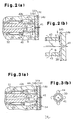
- FIG. 3(a) to 4 A second embodiment will be described referring to Figs. 3(a) to 4.
- This embodiment has the same construction as in the embodiment shown in Figs. 1 to 2(b), except that the passages between the second region B and the first region A are different from that in the foregoing embodiment. Therefore, the same or like parts as in the embodiment shown in Figs. 1 to 2(b) are affixed with the same reference numbers respectively, and a detailed description of them will be omitted.
- a cross-shaped hole 44 is defined in the first sub plate 14b of the valve plate assembly 14.
- the hole 44 is defined when forming of the suction valve 34 by using different press dies.
- the clearance between the restricting member 39 and the valve plate assembly 14 corresponds to the clearance ⁇ shown in Fig. 2(b).
- the size of the clearance between opposing parts of the restricting member 39 and the hole 44 is the sum of the clearance ⁇ and the thickness t of the first sub plate 14b.
- the refrigerant flows smoothly from the second region B into the first region A through this clearance ⁇ + t).
- This embodiment has the following effects in addition to those of the embodiment shown in Figs. 1 to 2(b).
- the hole 44 can be defined simultaneously when the first sub plate 14b is formed by slightly changing the dies used for forming the first sub plate 14b. Further, the passage between the second region B and the first region A can be defined easily, which reduces costs compared with the case where the holes 43 are defined in the restricting member 39 by drilling or the like.
- This embodiment may be modified as follows.
- both the first sub plate 14b and the main plate 14a may be machined.
- a circular first hole 45 and a plurality of second holes (four holes in this embodiment) 46 are defined in the first sub plate 14b.
- the first hole 45 is defined concentrically with the passage 41 and has a diameter smaller than the inside diameter of the restricting member 39.
- the second hole 46 is defined radially outside of the restricting member 39.
- elliptic recesses 47 are defined in the main plate 14a.
- the recesses 47 connect the first hole 45 to the second holes 46.
- the first hole 45, the second holes 46 and the recesses 47 define the passage between the second region B and the first region A.
- the first hole 45 and the second holes 46 are formed when the suction valve 34 is formed in the first sub plate 14b, and the recesses 47 are formed when forming the suction ports 33, discharge ports 35, etc. in the main plate 14a. Therefore, this embodiment has the same effects as in the embodiment shown in Figs. 3(a) to 4.
- the diameter of the outlet 42a of the axial passage 42 may be increased so that the restricting member 39 can be fitted in the axial passage 42.
- the effects of the embodiments shown in Figs. 1 to 6 can be obtained.
- the passage between the second region B and the first region A may be defined in the drive shaft 16.
- the restricting member 39 may be formed integrally at the rear end portion of the drive shaft 16. That is, the rear end of the drive shaft 16 is abutted directly against the valve plate assembly 14, and a hole 43 is defined in the rear end of the drive shaft 16.
- the cylindrical restricting member 39 may be press fitted in the holding space 40.
- the restricting member 39 in the state where the drive shaft 16 is urged forward by the compressive reaction force, the restricting member 39 is fixed such that a clearance ⁇ is defined between the restricting member 39 and the rear end of the drive shaft 16.
- the restricting member 39 is fixed in the holding space 40 such that a sufficient distance exists between the valve plate assembly 14 and the restricting member 39.
- a first hole 48 is defined at the center of the restricting member 39.
- a plurality of second holes 49 are defined as passages between the second region B and the first region A. This eliminates the need for fixing the restricting member 39 to the drive shaft 16 and for machining the valve plate assembly 14, and only the restricting member 39 is machined.
- a groove 50 is formed as the passage in the cylinder block 12.
- the degree of freedom in the size of the passage is increased compared with the embodiments where the passage is defined in the restricting member 39, and the groove 50 can be formed when forming the cylinder block 12, which simplifies the formation the restricting member 39.
- the axial passage 42 need not be defined in the drive shaft 16, but a bleed passage (not shown) may be defined separately in the cylinder block 12.
- the holding space 40 is allowed to communicate with the suction chamber 31 to permit flow of the refrigerant into it and to lubricate the second radial bearing 19.
- the present invention may be employed where power transmission from the drive source to the drive shaft 16 is achieved through a solenoid clutch.
- the clearance defined between the rotor of the solenoid clutch and the armature, when the solenoid is off, is larger than the clearance ⁇ between the restricting member 39 and the valve plate assembly 14 or between the restricting member 39 and the rear end face of the drive shaft 16. Therefore, even if the value of clearance ⁇ is not changed, the rotor and the armature do not interfere with each other when the solenoid clutch is off.
- the present invention may be applied to a wobble compressor in which the drive plate rotates relative to the drive shaft.
- the control valve 38 for adjusting the opening degree of the air supply passage is not limited to the solenoid valve.
- the control valve 38 may be, for example, one disclosed in Japanese Unexamined Patent Publication No. Hei 6-123281, which has a diaphragm that moves according to the suction pressure and a valve mechanism for controlling the opening degree of the air supply passage according to the position of the diaphragm.
- an externally controllable solenoid valve is preferred in a clutchless compressor.
- the drive source is not limited to the engine 30 but may be a motor.
- a variable displacement compressor includes a housing having a suction chamber (31).
- a crank chamber (15) is defined in the housing.
- a valve plate assembly (14) is located in the housing.
- a drive shaft (16) is supported in the housing.
- a radial bearing (19) is located in the housing.
- a holding bore (18) houses the rear end of the drive shaft (16) and the radial bearing (19).
- the holding bore (18) is connected to a holding space (40).
- a passage (41) connects the holding space (40) and the suction chamber (31).
- a restricting member (39) is located in the holding space (40). The restricting member (39) restricts axial movement of the drive shaft (16) and divides the holding space (40) into a first region (B) and a second region (A).
- a clearance ( ⁇ ) is formed between the restricting member (39) and the valve plate assembly (14). The clearance ( ⁇ ) disappears when the pressure of the crank chamber (15) is increased rapidly.
Abstract
Description
- The present invention relates to a variable displacement compressor having single-headed pistons, which is used, for example, in a vehicular air conditioning system.
- A variable displacement swash plate clutch compressor shown in Fig. 8 has a
solenoid clutch 101, which can interrupt power transmission from a vehicular engine Eg. The compressor also has a displacement control mechanism, which can reduce the displacement so that the solenoid clutch is not be turned on and off frequently when the cooling load is low. - The displacement control mechanism has a
swash plate 103 connected topistons 102 throughshoes 102a. Arotary support 105 is fixed to adrive shaft 104. Theswash plate 103 is connected to therotary support 105 through ahinge mechanism 106. The swashplate 103 is housed in thecrank chamber 107. The differential pressure between thecrank chamber 107 and the cylinder bores 18 varies to change the inclination angle of theswash plate 103. As the inclination angle of theswash plate 103 is changed, the stroke of eachpiston 102 is changed to change the displacement. - For example, when the pressure of the
crank chamber 107 is increased to increase the difference between the pressure of the pressures of thecylinder bore 108, the inclination angle of theswash plate 103 is reduced, which reduces the compressor displacement. In Fig. 8, theswash plate 103 indicated by the broken double-dashed line is at the minimum inclination position, where it abuts against a regulatingring 109 attached to thedrive shaft 104. When the internal pressure of thecrank chamber 107 is reduced to reduce the differential pressure thecylinder bores 108, the inclination angle of theswash plate 103 is increased to increase the compressor displacement. - Generally, in the step of compressing a refrigerant gas, the
piston 102, theswash plate 103, thehinge mechanism 106, therotary support 105 and thedrive shaft 104 transmit force to the internal wall surface of a housing 110 (leftward in Fig. 8) through a thrust bearing 111 due to the compression load on thepiston 102. - The internal pressure of the
crank chamber 107 remains high so that the compressor can be started from the minimum displacement state, at which the load torque is minimized, even if the solenoid clutch is turned on soon after it is turned off. Further, control of the compressor displacement is performed to minimize the displacement, regardless of the cooling load, to reduce load of the engine Eg during rapid acceleration of the vehicle. - When the internal pressure of the
crank chamber 107 is increased rapidly to minimize the displacement, theswash plate 103 may be pressed against the regulatingring 109 with excessive force, or therotary support 105 may be pulled strongly to the rear side of the compressor through thehinge mechanism 106. Thus, thedrive shaft 104 is caused to slide or shift backward (rightward in Fig. 8) along the axis L. - Upon such movement of the
drive shaft 104, the top dead center position of thepiston 102 shifts toward thevalve plate 112. Therefore, thepiston 102 may impinge upon thevalve plate 112 when reaching the top dead center position. This impingement causes vibrations and noise and may damage thepistons 102 or thevalve plate 112. - Also, when such backward movement of the
drive shaft 104 takes place when thesolenoid clutch 101 is turned off, anarmature 101a of thesolenoid clutch 101 moves toward arotor 101b to eliminate a clearance between thearmature 101a and therotor 101b or to bring thearmature 101a into contact with therotor 101b, which causes rattling or vibration and unnecessary power transmission. - To solve the above problems, a
spring 113 is located between thehousing 110 and thedrive shaft 104. Thespring 113 urges thedrive shaft 104 axially forward. - Japanese Unexamined Patent Publication No. Hei 11-62824 discloses a compressor having a restricting member for restricting axial shifting of the drive shaft. The restricting member is located in a hole in which the rear end of the drive shaft is fitted. The hole communicates with a suction chamber through a space. A sealing member, which prevents communication between a crank chamber and the space through the hole is applied around the rear end of the drive shaft.
- To securely prevent backward axial shifting of the
drive shaft 104 shown in Fig. 8, it is essential to use a verystiff spring 113. As a result, the thrust bearing 111 receives a great load from thespring 113, which reduces the life of the thrust bearing 111 and increases the power loss of the compressor at the thrust bearing 111. The increased power loss adversely affects the fuel consumption rate of the engine Eg that drives the compressor. - In the compressor disclosed in Japanese Unexamined Patent Publication No. Hei 11-62824, a sealing member is located in the hole in which the rear end of a drive shaft is supported. The sealing member prevents entry of refrigerant into the hole. Therefore, lubricant cannot be supplied fully to the radial bearing, which shortens the life of the bearing.
- It is an object of the present invention to provide a variable displacement compressor having a simple constitution and being capable of maintaining sufficient lubrication of the radial bearing.
- To achieve the above objective, the present invention provides a variable displacement compressor. The compressor comprises a housing having a suction chamber and a discharge chamber. A crank chamber is defined in the housing. A drive shaft has a front end and a rear end. The shaft is supported in the housing so that the front end protrudes from the housing. A cylinder block forms part of the housing. Cylinder bores are defined in the cylinder block. A valve plate assembly includes a suction port, a suction valve, a discharge port and a discharge valve for each cylinder bore. Single-headed pistons are housed in the cylinder bores, respectively. A drive plate is housed in the crank chamber and is connected to the pistons to convert rotation of the drive shaft into reciprocating motion of the pistons. The drive plate rotates integrally with the drive shaft. A control mechanism controls inclination of the drive plate by controlling the pressure of the crank chamber to change the volume of a refrigerant discharged from each cylinder bore into the discharge chamber. A radial bearing supports the rear end of the drive shaft. The refrigerant flows through the radial bearing. A holding bore houses the rear end of the drive shaft and the radial bearing. The holding bore is connected to a holding space. The holding space is defined by the valve plate assembly. A passage connects the holding space and the suction chamber. A restricting member is located in the holding space. The restricting member restricts axial movement of the drive shaft and divides the holding space into a first region and a second region. The first region and the second region communicate with each other. A clearance is formed between the drive shaft and the restricting member or between the restricting member and the valve plate assembly in a normal compressing operation. The clearance disappears when the pressure of the crank chamber is increased rapidly by the control mechanism.
- The present invention also provides a variable displacement compressor. The compressor comprises a housing having a suction chamber and a discharge chamber. A crank chamber is defined in the housing. A drive shaft has a front end and a rear end. The shaft is supported in the housing so that the front end protrudes from the housing. A cylinder block forms part of the housing. Cylinder bores are defined in the cylinder block. A valve plate assembly includes a suction port, a suction valve, a discharge port and a discharge valve for each cylinder bore. Single-headed pistons are housed in the cylinder bores, respectively. A drive plate is housed in the crank chamber and is connected to the pistons to convert rotation of the drive shaft into reciprocating motion of the pistons. The drive plate rotates integrally with the drive shaft. A control mechanism controls inclination of the drive plate by controlling the pressure of the crank chamber to change the volume of a refrigerant discharged from each cylinder bore into the discharge chamber. A radial bearing supports the rear end of the drive shaft. The refrigerant flows through the radial bearing. A holding bore houses the rear end of the drive shaft and the radial bearing. The holding bore is connected to a holding space. The holding space is defined by the valve plate assembly. The holding space is connected to the suction chamber. Means for restricting restricts axial movement of the drive shaft. The restricting means are located in the holding space and divides the holding space into a first region and a second region. A clearance is formed between the drive shaft and the restricting means or between the restricting means and the valve plate assembly in a normal compressing operation. The clearance disappears when the pressure of the crank chamber is increased rapidly by the control mechanism. A passage connects the first region to the second region.
- The present invention also provides a variable displacement compressor. The compressor comprises a housing having a suction chamber and a discharge chamber. A crank chamber is defined in the housing. A drive shaft has a front end and a rear end. The shaft is supported in the housing so that the front end protrudes from the housing. A cylinder block forms part of the housing. Cylinder bores are defined in the cylinder block. A valve plate assembly includes a suction port, a suction valve, a discharge port and a discharge valve for each cylinder bore. Single-headed pistons are housed in the cylinder bores, respectively. A drive plate is housed in the crank chamber and is connected to the pistons to convert rotation of the drive shaft into reciprocating motion of the pistons. The drive plate rotates integrally with the drive shaft. A control mechanism controls inclination of the drive plate by controlling the pressure of the crank chamber to change the volume of a refrigerant discharged from each cylinder bore into the discharge chamber. A radial bearing supports the rear end of the drive shaft. The refrigerant flows through the radial bearing. A holding bore houses the rear end of the drive shaft and the radial bearing. The holding bore is connected to a holding space. The holding space is defined by the valve plate assembly. A passage connects the holding space and the suction chamber. A cylindrical body is located in the holding space. One end of the cylindrical body is fixed to the drive shaft, and the other end of the cylindrical body abuts against the valve plate assembly. The cylindrical body restricts axial movement of the drive shaft and divides the holding space into a first region and a second region. The cylindrical body has a hole to connect the first region to the second region. A clearance is formed between the drive shaft and the cylindrical body or between the cylindrical body and the valve plate assembly in a normal compressing operation. The clearance disappears when the internal pressure of the crank chamber is increased rapidly by the control mechanism.
- Other aspects and advantages of the invention will become apparent from the following description, taken in conjunction with the accompanying drawings, illustrating by way of examples the principles of the invention.
- The invention together with objects and advantages thereof, may best be understood by reference to the following description of the presently preferred embodiments together with the accompanying drawings in which:
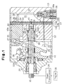
- Fig. 1 is a cross-sectional view of the variable displacement compressor according to a first embodiment of the present invention;
- Fig. 2(a) is an enlarged partial cross-sectional view of the compressor shown in Fig. 1;
- Fig. 2(b) is an enlarged cross-sectional view showing actions of the passage at the portion shown in Fig. 2(a);
- Fig. 3(a) is an enlarged partial cross-sectional view of the compressor according to a second embodiment of the present invention, showing a portion corresponding to that in Fig. 2(a);
- Fig. 3(b) is a cross-sectional view taken along the
line 3b-3b in Fig. 3(a); - Fig. 4 is an enlarged cross-sectional view showing actions of the passage at the portion shown in Fig. 3(a);
- Fig. 5(a) is an enlarged cross-sectional view of the compressor according to a third embodiment of the present invention, showing a portion corresponding to that in Fig. 2(a);
- Fig. 5(b) is a cross-sectional view taken along the
line 5b-5b in Fig. 5(a); - Fig. 6 is an enlarged cross-sectional view showing actions of the passage at the portion shown in Fig. 5(a);
- Fig. 7(a) is an enlarged cross-sectional view of the compressor according to a fourth embodiment of the present invention, showing a portion corresponding to that in Fig. 2(a);
- Fig. 7(b) is an enlarged cross-sectional view of the compressor according to a fifth embodiment of the present invention, showing a portion corresponding to that in Fig. 2(a); and
- Fig. 8 is a cross-sectional view of a variable displacement compressor of the prior art.
-
- The variable displacement compressor according to the first embodiment of the present invention is part of a vehicular air conditioning system and is described below referring to Figs. 1 and 2(b).
- As shown in Fig. 1, a
front housing member 11 is connected to the front end of acylinder block 12. Arear housing member 13 is connected to the rear end of thecylinder block 12 through avalve plate assembly 14. Thefront housing member 11, thecylinder block 12 and therear housing member 13 are fastened together with through-bolts (not shown). Thefront housing member 11, thecylinder block 12 and therear housing member 13 form a housing of the compressor. The left side and the right side in Fig. 1 correspond to the front end and the rear end, respectively. - The
valve plate assembly 14 includes amain plate 14a, afirst sub plate 14b, asecond sub plate 14c and aretainer plate 14d. Thefirst sub plate 14b and thesecond sub plate 14c are superposed on the front side and on the rear side of themain plate 14a, respectively. Theretainer plate 14d is superposed on the rear side of thesecond sub plate 14c. Thefirst sub plate 14b of thevalve plate assembly 14 is connected to thecylinder block 12. - A
crank chamber 15 is defined between thefront housing member 11 and thecylinder block 12. Adrive shaft 16 passes through thecrank chamber 15. Thedrive shaft 16 is supported between thefront housing member 11 and thecylinder block 12, and the front end of thedrive shaft 16 extends from the housing. The front end of thedrive shaft 16 is supported in thefront housing member 11 by a firstradial bearing 17. A holding bore 18 is defined substantially at the center of thecylinder block 12. The rear end of thedrive shaft 16 is supported by a secondradial bearing 19 located in the holding bore 18. Ashaft sealing device 20 is applied around the front end of thedrive shaft 16. Thedevice 20 prevents leakage of refrigerant. - A plurality of cylinder bores 12a (only one cylinder bore is shown in Fig. 1) are defined in the
cylinder block 12. The cylinder bores 12a are defined at equiangular intervals around the axis L of thedrive shaft 16. Single-headedpistons 21 are housed in the cylinder bores 12a. Openings of eachcylinder bore 12a are closed by thevalve plate assembly 14 and thecorresponding piston 21. Acompression chamber 22 is defined in eachcylinder bore 12a. The volume of eachcompression chamber 22 varies as the correspondingpiston 21 reciprocates. - In the
crank chamber 15, alug plate 23 is fixed to and rotates integrally with thedrive shaft 16. Athrust bearing 24 is located between thelug plate 23 and theinternal wall surface 11a of thefront housing member 11. Theinternal wall surface 11a bears the load of the compressive reaction force of thepistons 21 and functions as a regulating surface that regulates axial movement of thedrive shaft 16. - A
swash plate 25, or drive plate, is housed in thecrank chamber 15. Theswash plate 25 is supported such that it slides and on and inclines with respect to thedrive shaft 16. Ahinge mechanism 26 is located between thelug plate 23 and theswash plate 25. Theswash plate 25 is connected to thelug plate 23 through thehinge mechanism 26 and to thedrive shaft 16. Theswash plate 25 rotates synchronously with thelug plate 23 and thedrive shaft 16. - The
pistons 21 are connected to the periphery of theswash plate 25 throughshoes 27, respectively. Thus, theswash plate 25 is rotated by thedrive shaft 16, and the rotational motion of theswash plate 25 is converted to reciprocating motions of thepistons 21 through theshoes 27. - A regulating
ring 28 is fitted to thedrive shaft 16 between theswash plate 25 and thecylinder block 12. The minimum inclination angle of theswash plate 25, as indicated by the broken double-dashed line in Fig. 1, is determined by abutment of theswash plate 25 against the regulatingring 28. The maximum inclination angle of theswash plate 25, as indicated by the solid line in Fig. 1, is determined by abutment against thelug plate 23. - The
drive shaft 16 is connected to anengine 30 through apower transmission mechanism 29. Thepower transmission mechanism 29 may be a clutch mechanism (e.g., a solenoid clutch), which transmits or interrupts of power according to an external electrical controller, or a normally transmitting type clutchless mechanism (e.g., a belt/pulley combination). Here, in this embodiment, a clutchlesspower transmission mechanism 29 is employed. - A
suction chamber 31 is defined in therear housing member 13. Adischarge chamber 32 is defined in therear housing member 13 at a position radially outward from thesuction chamber 31. Thevalve plate assembly 14 has, for eachcylinder bore 12a, asuction port 33, asuction valve 34 for opening and closing thesuction port 33, adischarge port 35 and adischarge valve 36 for opening and closing thedischarge port 35. Thesuction chamber 31 communicates with the cylinder bores 12a through thesuction ports 33. Thedischarge chamber 32 communicates with the cylinder bores 12a through thedischarge ports 35. Thesuction chamber 31 and thedischarge chamber 32 are connected to each other through an external refrigerant circuit (not shown). - The
cylinder block 12 and therear housing member 13 contain angas supply passage 37 that connects thecrank chamber 15 and thedischarge chamber 32. Acontrol valve 38, which is a solenoid valve, is located in thegas supply passage 37. Thecontrol valve 38 has a valve chamber forming part of thegas supply passage 37. Energization of asolenoid 38a opens thegas supply passage 37, and deenergization of thesolenoid 38a closes thegas supply passage 37. Further, the opening degree of thegas supply passage 37 is adjusted depending on the level of the current energizing thesolenoid 38a. - A holding
space 40 is defined behind the holding bore 18. A restrictingmember 39 is housed in the holdingspace 40. The restrictingmember 39 restricts backward movement of thedrive shaft 16. The holdingspace 40 is connected at one end the holding bore 18 and is closed at the other end by thevalve plate assembly 14. The holdingspace 40 and thesuction chamber 31 communicate with each other through apassage 41 defined in thevalve plate assembly 14. Thepassage 41 is aligned with the axis L of thedrive shaft 16. - The
drive shaft 16 has anaxial passage 42 that connects the holdingspace 40 and thecrank chamber 15. Aninlet 42a and anoutlet 42b of theaxial passage 42 open at the rear of the firstradial bearing 17 and to the rear end face of thedrive shaft 16, respectively. Theaxial passage 42, the holding bore 18, the holdingspace 40 and thepassage 41 form a bleed passage for connecting thecrank chamber 15 and thesuction chamber 31. Thepassage 41 functions as a restrictor. - The restricting
member 39, which is a cylindrical, is fixed to the rear end of thedrive shaft 16. The restrictingmember 39 is designed to have an outside diameter that is smaller than the inside diameter of the secondradial bearing 19, and therestriction member 39 is fixed to a small-diameter portion 16a formed at the rear end of thedrive shaft 16. - As shown in Fig. 2(b), in a normal compressing operation, a small clearance Δ is defined between the restricting
member 39 and thevalve plate assembly 14. When the internal pressure of thecrank chamber 15 is increased suddenly, the clearance Δ disappears, and backward movement of thedrive shaft 16 is restricted. The clearance Δ is, for example, about 0.1 mm. This clearance Δ is smaller than the clearance between thepiston 21 at the top dead center position and thevalve plate assembly 14. - As shown in Figs. 2(a) and 2(b), the restricting
member 39 divides the holdingspace 40 into a first region A and a second region B. The resistance of the refrigerant gas passing from the second region B to the first region A through the clearance Δ is greater than the resistance of the refrigerant gas flowing from thecrank chamber 15 through the secondradial bearing 19 into the holdingspace 40. - A plurality of
holes 43 are defined in the restrictingmember 39 to form passages connecting the first region A and the second region B. Theholes 43 are defined such that the resistance of the refrigerant gas passing through is smaller than that passing through the secondradial bearing 19. - The operation of the compressor described above will be described below.
- When the
drive shaft 16 is rotated, theswash plate 25 is rotated integrally through thelug plate 23 and thehinge mechanism 26, and the rotation of theswash plate 25 is converted into reciprocating motion of thepistons 21 through theshoes 27. Consequently, suction, compression and discharge of the refrigerant are repeated sequentially in eachcompression chamber 22. Refrigerant supplied from an external refrigerant circuit into thesuction chamber 31 is drawn through thesuction port 33 into thecompression chamber 22. Travel of thepiston 21 to the top dead center compresses the refrigerant in thecompression chamber 22 to a predetermined pressure and discharges the compressed refrigerant through thedischarge port 35 into thedischarge chamber 32. The refrigerant discharged into thedischarge chamber 32 is fed through a discharge passage to the external refrigerant circuit. - A controller (not shown) adjusts the valve position of the
control valve 38, i.e., the opening degree of thegas supply passage 37, depending on the cooling load. As a result, the flow rate of gas between thedischarge chamber 32 and thecrank chamber 15 is changed. - When the cooling load is high, the opening degree of the
gas supply passage 37 is reduced to reduce the flow rate of the refrigerant gas supplied from thedischarge chamber 32 into thecrank chamber 15. When the amount of refrigerant gas supplied to the crankchamber 15 decreases, the internal pressure of thecrank chamber 15 is reduced gradually due to the release of refrigerant gas through theaxial passage 42 into thesuction chamber 31. Thus, the differential pressure between the pressure of thecrank chamber 15 and that of the cylinder bore 12a decreases, which moves theswash plate 25 to the maximum inclination position. Therefore, the stroke of thepiston 21 is increased, which increases the displacement. - When the cooling load is low, the
control valve 38 is opened to increase the flow rate of refrigerant gas from thedischarge chamber 32 into thecrank chamber 15. If the amount of refrigerant gas supplied to the crankchamber 15 exceeds the flow rate of refrigerant gas flowing out through theaxial passage 42 into thesuction chamber 31, the internal pressure of thecrank chamber 15 increases gradually. Thus, the differential pressure between thecrank chamber 15 and thecylinder bore 12a increases, which moves theswash plate 25 to the minimum inclination angle position. This reduces the stroke of eachpiston 21, and reduces the displacement. - The compression load of the refrigerant gas acting upon each
piston 21 is applied to theinternal wall surface 11a of thefront housing member 11 through theshoes 27, theswash plate 25, thehinge mechanism 26, thelug plate 23 and thethrust bearing 24. Generally, in the compressing operation, forward movement of thedrive shaft 16, theswash plate 25, thelug plate 23, and thepistons 21 along the axis L is restricted by theinternal wall surface 11a of thefront housing member 11 through thethrust bearing 24. When thewall surface 11a restricts the forward axial movement of thedrive shaft 16, a clearance Δ exists between the restrictingmember 39 and thevalve plate assembly 14. Accordingly, the restrictingmember 39 does not interfere with the rotation of thedrive shaft 16. - When the compressor is operating at the maximum displacement and is subjected to displacement restricting control, the
control valve 38 causes thegas supply passage 37 to open suddenly from a closed state. Thus, the highpressure refrigerant in thedischarge chamber 32 is supplied rapidly to the crankchamber 15. The pressure of thecrank chamber 15 increases rapidly, since additional refrigerant can not be rapidly through theaxial passage 42. The sudden increase in the pressure of thecrank chamber 15 rapidly reduces the inclination angle of theswash plate 25. This causes the swash plate 25 (indicated by the broken double-dashed line in Fig. 1) to be pressed against the regulatingring 28 with an excessive force, which pulls thelug plate 23 strongly backward through thehinge mechanism 26. Thus, thedrive shaft 16 slides backward along the axis L. The restrictingmember 39 thus abuts against thevalve plate assembly 14 to restrict backward movement of thedrive shaft 16. Therefore, the distal end of thepiston 21 is prevented from connecting the valve plate assembly when thepiston 21 reaches the top dead center position. - During rotation of the
drive shaft 16, some refrigerant flows from thepassage 41 into thesuction chamber 31 through theaxial passage 42 and the holdingspace 40 due to the differential pressure between thecrank chamber 15 and thesuction chamber 31. Atomized lubricant in the refrigerant lubricates thethrust bearing 24 and the firstradial bearing 17. - Some of the refrigerant gas in the
crank chamber 15 flows through the secondradial bearing 19 into the second region B of the holdingspace 40. The secondradial bearing 19 is lubricated by the atomized lubricant contained in the refrigerant flowing from thecrank chamber 15 toward the holdingspace 40. During normal operation of the compressor, there is a very small clearance Δ present between the restrictingmember 39 and thevalve plate assembly 14. If the second region B and the first region A could communicate with each other only through the clearance Δ, the refrigerant would not move smoothly from the second region B to the first region A. Thus, the amount of refrigerant passing through the secondradial bearing 19 would decrease and the secondradial bearing 19 would not be adequately lubricated. Particularly, in the case of clutchless compressors, the secondradial bearing 19 is lubricated insufficiently during minimum displacement operation. - However, in this embodiment, the restricting
member 39 includes theholes 43, and the refrigerant thus passes from the second region B to the first region A smoothly. As a result, the refrigerant flowing from thecrank chamber 15 toward the holdingspace 40 through the secondradial bearing 19 thoroughly lubricates the secondradial bearing 19. - This embodiment has the following effects.
- A reduction in the amount of refrigerant passing through the second
radial bearing 19 is avoided by formingholes 43 between the first region A and the second region B. Thus, impingement of thepistons 21 against thevalve plate assembly 14 caused by backward movement of thedrive shaft 16 is avoided, even in the absence of thespring 113 shown in Fig. 8. Further, the secondradial bearing 19 is thoroughly lubricated. In addition, the load acting upon thethrust bearing 24 is reduced compared with constitution compressors that employ thespring 113. This reduces friction and thus reduces the power loss of the compressor, which improves the fuel consumption of theengine 30. The present invention has a particularly significant effect in clutchless compressors. - Use of the restricting
member 39 in which holes 43 are formed permits thorough lubrication of the secondradial bearing 19 and restricts backward movement of thedrive shaft 16. The number and the diameter of theholes 43 can be changed arbitrarily. - The restricting
member 39 is fitted on thedrive shaft 16. Therefore, the assembly is simple. - The outside diameter of the restricting
member 39 is smaller than the inside diameter of the secondradial bearing 19. Therefore, during assembly of the compressor, the restrictingmember 39 can be installed in the compressor after it is fitted on thedrive shaft 16. This facilitates assembly. - The holding
space 40 is located between the holding bore 18 and thevalve plate assembly 14. Therefore, the space used for housing thespring 113 shown in Fig. 8 is used as the holdingspace 40. Thus, space for the restrictingmember 39 is available, and there is no need to enlarge the compressor. - A second embodiment will be described referring to Figs. 3(a) to 4. This embodiment has the same construction as in the embodiment shown in Figs. 1 to 2(b), except that the passages between the second region B and the first region A are different from that in the foregoing embodiment. Therefore, the same or like parts as in the embodiment shown in Figs. 1 to 2(b) are affixed with the same reference numbers respectively, and a detailed description of them will be omitted.
- A
cross-shaped hole 44 is defined in thefirst sub plate 14b of thevalve plate assembly 14. Thehole 44 is defined when forming of thesuction valve 34 by using different press dies. - As shown in Fig. 4, the clearance between the restricting
member 39 and thevalve plate assembly 14 corresponds to the clearance Δ shown in Fig. 2(b). The size of the clearance between opposing parts of the restrictingmember 39 and thehole 44 is the sum of the clearance Δ and the thickness t of thefirst sub plate 14b. The refrigerant flows smoothly from the second region B into the first region A through this clearance Δ + t). - This embodiment has the following effects in addition to those of the embodiment shown in Figs. 1 to 2(b).
- The
hole 44 can be defined simultaneously when thefirst sub plate 14b is formed by slightly changing the dies used for forming thefirst sub plate 14b. Further, the passage between the second region B and the first region A can be defined easily, which reduces costs compared with the case where theholes 43 are defined in the restrictingmember 39 by drilling or the like. - This embodiment may be modified as follows.
- If the passage connecting the second region B and the first region A is defined in the
valve plate assembly 14, both thefirst sub plate 14b and themain plate 14a may be machined. For example, as in a third embodiment shown in Figs. 5(a), 5(b) and 6, a circularfirst hole 45 and a plurality of second holes (four holes in this embodiment) 46 are defined in thefirst sub plate 14b. Thefirst hole 45 is defined concentrically with thepassage 41 and has a diameter smaller than the inside diameter of the restrictingmember 39. Thesecond hole 46 is defined radially outside of the restrictingmember 39. - As shown in Figs. 5(a) and 5(b), four
elliptic recesses 47 are defined in themain plate 14a. Therecesses 47 connect thefirst hole 45 to the second holes 46. In this embodiment, thefirst hole 45, thesecond holes 46 and therecesses 47 define the passage between the second region B and the first region A. Thefirst hole 45 and thesecond holes 46 are formed when thesuction valve 34 is formed in thefirst sub plate 14b, and therecesses 47 are formed when forming thesuction ports 33,discharge ports 35, etc. in themain plate 14a. Therefore, this embodiment has the same effects as in the embodiment shown in Figs. 3(a) to 4. - In the embodiment shown in Figs. 3(a) to 4, in the state where the restricting
member 39 is abutted against thevalve plate assembly 14, the end face of the restrictingmember 39 is brought into direct contact with the periphery of thehole 44. In the embodiment shown in Figs. 5(a), 5(b) and 6, in the state where the restrictingmember 39 is abutted against thevalve plate assembly 14, the restrictingmember 39 is not engaged with the passage defined in thevalve plate assembly 14. - Instead of fitting the restricting
member 39 to the small-diameter rear end portion of thedrive shaft 16, the diameter of theoutlet 42a of theaxial passage 42 may be increased so that the restrictingmember 39 can be fitted in theaxial passage 42. In this case, the effects of the embodiments shown in Figs. 1 to 6 can be obtained. - The passage between the second region B and the first region A may be defined in the
drive shaft 16. - The restricting
member 39 may be formed integrally at the rear end portion of thedrive shaft 16. That is, the rear end of thedrive shaft 16 is abutted directly against thevalve plate assembly 14, and ahole 43 is defined in the rear end of thedrive shaft 16. - The cylindrical restricting
member 39 may be press fitted in the holdingspace 40. For example, as in a fourth embodiment shown in Fig. 7(a), in the state where thedrive shaft 16 is urged forward by the compressive reaction force, the restrictingmember 39 is fixed such that a clearance Δ is defined between the restrictingmember 39 and the rear end of thedrive shaft 16. The restrictingmember 39 is fixed in the holdingspace 40 such that a sufficient distance exists between thevalve plate assembly 14 and the restrictingmember 39. - A
first hole 48 is defined at the center of the restrictingmember 39. A plurality ofsecond holes 49 are defined as passages between the second region B and the first region A. This eliminates the need for fixing the restrictingmember 39 to thedrive shaft 16 and for machining thevalve plate assembly 14, and only the restrictingmember 39 is machined. - In a fifth embodiment shown in Fig. 7(b), a
groove 50 is formed as the passage in thecylinder block 12. In this case, the degree of freedom in the size of the passage is increased compared with the embodiments where the passage is defined in the restrictingmember 39, and thegroove 50 can be formed when forming thecylinder block 12, which simplifies the formation the restrictingmember 39. - The
axial passage 42 need not be defined in thedrive shaft 16, but a bleed passage (not shown) may be defined separately in thecylinder block 12. In this case, the holdingspace 40 is allowed to communicate with thesuction chamber 31 to permit flow of the refrigerant into it and to lubricate the secondradial bearing 19. - The present invention may be employed where power transmission from the drive source to the
drive shaft 16 is achieved through a solenoid clutch. In this case, the clearance defined between the rotor of the solenoid clutch and the armature, when the solenoid is off, is larger than the clearance Δ between the restrictingmember 39 and thevalve plate assembly 14 or between the restrictingmember 39 and the rear end face of thedrive shaft 16. Therefore, even if the value of clearance Δ is not changed, the rotor and the armature do not interfere with each other when the solenoid clutch is off. - The present invention may be applied to a wobble compressor in which the drive plate rotates relative to the drive shaft.
- The
control valve 38 for adjusting the opening degree of the air supply passage is not limited to the solenoid valve. Thecontrol valve 38 may be, for example, one disclosed in Japanese Unexamined Patent Publication No. Hei 6-123281, which has a diaphragm that moves according to the suction pressure and a valve mechanism for controlling the opening degree of the air supply passage according to the position of the diaphragm. However, an externally controllable solenoid valve is preferred in a clutchless compressor. - The drive source is not limited to the
engine 30 but may be a motor. - It should be apparent to those skilled in the art that the present invention may be embodied in many other specific forms without departing from the spirit or scope of the invention. Particularly, it should be understood that the invention may be embodied in the following forms.
- Therefore, the present examples and embodiments are to be considered as illustrative and not restrictive, and the invention is not to be limited to the details given herein, but may be modified within the scope of the appended claims.
- A variable displacement compressor includes a housing having a suction chamber (31). A crank chamber (15) is defined in the housing. A valve plate assembly (14) is located in the housing. A drive shaft (16) is supported in the housing. A radial bearing (19) is located in the housing. A holding bore (18) houses the rear end of the drive shaft (16) and the radial bearing (19). The holding bore (18) is connected to a holding space (40). A passage (41) connects the holding space (40) and the suction chamber (31). A restricting member (39) is located in the holding space (40). The restricting member (39) restricts axial movement of the drive shaft (16) and divides the holding space (40) into a first region (B) and a second region (A). A clearance (Δ) is formed between the restricting member (39) and the valve plate assembly (14). The clearance (Δ) disappears when the pressure of the crank chamber (15) is increased rapidly.
Claims (9)
- A variable displacement compressor comprising:a housing having a suction chamber (31) and a discharge chamber (32);a crank chamber (15) defined in the housing;a drive shaft (16) having a front end and a rear end, the shaft being supported in the housing so that the front end protrudes from the housing;a cylinder block (12) forming part of the housing, wherein cylinder bores (12a) are defined in the cylinder block (12);a valve plate assembly (14), which includes a suction port (33), a suction valve (34), a discharge port (35) and a discharge valve (36) for each cylinder bore (12a);single-headed pistons (21) housed in the cylinder bores (12a), respectively;a drive plate (25), which is housed in the crank chamber (15) and is connected to the pistons (21) to convert rotation of the drive shaft (16) into reciprocating motion of the pistons (21), wherein the drive plate (25) rotates integrally with the drive shaft (16);a control mechanism (38), which controls inclination of the drive plate (25) by controlling the pressure of the crank chamber (15) to change the volume of a refrigerant discharged from each cylinder bore into the discharge chamber (32);a radial bearing (19) supporting the rear end of the drive shaft (16), wherein the refrigerant flows through the radial bearing (19);a holding bore (18), in which the rear end of the drive shaft (16) and the radial bearing (19) are located, wherein the holding bore (18) is connected to a holding space (40), and the holding space (40) is defined by the valve plate assembly (14);a passage (41) connecting the holding space (40) and the suction chamber (31), the compressor being characterized by:a restricting member (39) located in the holding space (40), wherein the restricting member (39) restricts axial movement of the drive shaft (16) and divides the holding space (40) into a first region (B) and a second region (A), and the first region (B) and the second region (A) communicate with each other, wherein a clearance (Δ) is formed between the drive shaft (16) and the restricting member (39) or between the restricting member (39) and the valve plate assembly (14) in a normal compressing operation, and the clearance (Δ) disappears when the pressure of the crank chamber (15) is increased rapidly by the control mechanism (38).
- The variable displacement compressor according to Claim 1, characterized in that the resistance of the refrigerant when it passes from the first region (B) to the second region (A) is less than that when the refrigerant passes through the radial bearing (19).
- The variable displacement compressor according to Claims 1 or 2, characterized in that the restricting member (39) has a cylindrical shape, and one end of the restricting member (39) is fixed to the drive shaft (16), and the other end of the restricting member (39) abuts against the valve plate assembly (14).
- The variable displacement compressor according to any one of Claims 1 to 3, characterized in that a hole (43, 48, 49) is defined in the restricting member (39) to connect the first region (B) and the second region (A).
- The variable displacement compressor according to Claim 3, characterized in that a passage (44, 46, 47) is defined in the valve plate assembly (14) to connect the first region (B) and the second region (A).
- The variable displacement compressor according to Claim 5, characterized in that the valve plate assembly (14) has a first sub plate (14b), a second sub plate (14c) and a main plate (14a), wherein the main plate (14a) is located between the first and the second subplates (14b, 14c), and the passage (44) is defined in the first sub plate (14b).
- The variable displacement compressor according to Claim 5, characterized in that the valve plate assembly (14) has a first sub plate, a second sub plate and a (14) has a first sub plate (14b), a second sub plate (14c) and a main plate (14a), wherein the main plate (14a) is located between the first and the second subplates (14b, 14c), and the passage (46, 47) is defined in the main plate (14a) and the first sub plate (14b).
- The variable displacement compressor according to any one of Claims 1 to 4, characterized in that the restricting member (39) is press fitted into the holding space (40) such that a predetermined clearance exists between the restricting member (39) and the valve plate assembly (14).
- The variable displacement compressor according to Claim 8, characterized in that a passage (50) is defined in the cylinder block (12) between the first region (B) and the second region (A).
Applications Claiming Priority (2)
| Application Number | Priority Date | Filing Date | Title |
|---|---|---|---|
| JP2000194658A JP2002013474A (en) | 2000-06-28 | 2000-06-28 | Variable displacement compressor |
| JP2000194658 | 2000-06-28 |
Publications (2)
| Publication Number | Publication Date |
|---|---|
| EP1167764A2 true EP1167764A2 (en) | 2002-01-02 |
| EP1167764A3 EP1167764A3 (en) | 2003-08-13 |
Family
ID=18693447
Family Applications (1)
| Application Number | Title | Priority Date | Filing Date |
|---|---|---|---|
| EP01115485A Withdrawn EP1167764A3 (en) | 2000-06-28 | 2001-06-27 | Variable displacement swash plate compressor |
Country Status (6)
| Country | Link |
|---|---|
| US (1) | US6663355B2 (en) |
| EP (1) | EP1167764A3 (en) |
| JP (1) | JP2002013474A (en) |
| KR (1) | KR100428822B1 (en) |
| CN (1) | CN1133811C (en) |
| BR (1) | BR0102736A (en) |
Cited By (1)
| Publication number | Priority date | Publication date | Assignee | Title |
|---|---|---|---|---|
| EP1426617A2 (en) * | 2002-12-05 | 2004-06-09 | Kabushiki Kaisha Toyota Jidoshokki | Method of adjusting the clearance in a rotary machine |
Families Citing this family (19)
| Publication number | Priority date | Publication date | Assignee | Title |
|---|---|---|---|---|
| JP4385516B2 (en) * | 2000-11-07 | 2009-12-16 | 株式会社豊田自動織機 | Piston compressor |
| JP4824265B2 (en) * | 2000-11-23 | 2011-11-30 | ルーク ファールツォイク・ヒドラウリク ゲゼルシャフト ミット ベシュレンクテル ハフツング ウント コンパニー コマンディートゲゼルシャフト | compressor |
| JP4078229B2 (en) * | 2002-03-20 | 2008-04-23 | カルソニックカンセイ株式会社 | Compressor |
| JP2004124876A (en) * | 2002-10-04 | 2004-04-22 | Toyota Industries Corp | Variable displacement swash plate type compressor |
| JP4438811B2 (en) * | 2003-01-16 | 2010-03-24 | 株式会社デンソー | Compressor |
| US8197231B2 (en) | 2005-07-13 | 2012-06-12 | Purity Solutions Llc | Diaphragm pump and related methods |
| US7611335B2 (en) | 2006-03-15 | 2009-11-03 | Delphi Technologies, Inc. | Two set-point pilot piston control valve |
| JP4820269B2 (en) * | 2006-10-25 | 2011-11-24 | サンデン株式会社 | Reciprocating compressor |
| JP2009209910A (en) * | 2008-03-06 | 2009-09-17 | Toyota Industries Corp | Swash plate compressor |
| KR100986943B1 (en) * | 2008-08-13 | 2010-10-12 | 주식회사 두원전자 | Discharge valve for reciprocating compressor |
| JP5391648B2 (en) * | 2008-10-28 | 2014-01-15 | 株式会社豊田自動織機 | Capacity control mechanism in variable capacity compressor |
| WO2011078547A2 (en) * | 2009-12-23 | 2011-06-30 | 두원공과대학교 | Variable capacity compressor |
| KR101107049B1 (en) * | 2010-10-12 | 2012-01-25 | (주) 이더 | The plc training table |
| JP5999622B2 (en) * | 2012-02-06 | 2016-09-28 | サンデンホールディングス株式会社 | Variable capacity compressor |
| US9610392B2 (en) | 2012-06-08 | 2017-04-04 | Fresenius Medical Care Holdings, Inc. | Medical fluid cassettes and related systems and methods |
| JP6136906B2 (en) * | 2013-12-11 | 2017-05-31 | 株式会社豊田自動織機 | Variable capacity swash plate compressor |
| US20170067457A1 (en) * | 2015-09-09 | 2017-03-09 | Denso International America, Inc. | Variable compressor |
| JP7213700B2 (en) * | 2019-01-29 | 2023-01-27 | サンデン株式会社 | compressor |
| JP7213709B2 (en) * | 2019-02-06 | 2023-01-27 | サンデン株式会社 | compressor |
Citations (3)
| Publication number | Priority date | Publication date | Assignee | Title |
|---|---|---|---|---|
| US5584670A (en) * | 1994-04-15 | 1996-12-17 | Kabushiki Kaisha Toyoda Jidoshokki Seisakusho | Piston type variable displacement compressor |
| US5616008A (en) * | 1995-03-30 | 1997-04-01 | Kabushiki Kaisha Toyoda Jidoshokki Seisakusho | Variable displacement compressor |
| JPH1162824A (en) * | 1997-08-08 | 1999-03-05 | Sanden Corp | Variable capacity compressor |
Family Cites Families (8)
| Publication number | Priority date | Publication date | Assignee | Title |
|---|---|---|---|---|
| JPH08109880A (en) * | 1994-10-11 | 1996-04-30 | Toyota Autom Loom Works Ltd | Operation control system for variable displacement type compressor |
| JPH08338362A (en) * | 1995-06-08 | 1996-12-24 | Toyota Autom Loom Works Ltd | Variable displacement type swash plate type compressor |
| JPH10131850A (en) * | 1996-10-25 | 1998-05-19 | Toyota Autom Loom Works Ltd | Compressor |
| JPH10169557A (en) * | 1996-12-06 | 1998-06-23 | Toyota Autom Loom Works Ltd | Compressor |
| JPH10169558A (en) * | 1996-12-09 | 1998-06-23 | Toyota Autom Loom Works Ltd | Single-head piston type compressor |
| JPH10281060A (en) * | 1996-12-10 | 1998-10-20 | Toyota Autom Loom Works Ltd | Variable displacement compressor |
| JPH1182667A (en) | 1997-09-11 | 1999-03-26 | Sanden Corp | Power transmission device |
| JPH11241681A (en) * | 1997-12-26 | 1999-09-07 | Toyota Autom Loom Works Ltd | Protective device of seal mechanism in compressor |
-
2000
- 2000-06-28 JP JP2000194658A patent/JP2002013474A/en active Pending
-
2001
- 2001-04-27 KR KR10-2001-0022970A patent/KR100428822B1/en not_active IP Right Cessation
- 2001-06-27 BR BR0102736-0A patent/BR0102736A/en not_active IP Right Cessation
- 2001-06-27 EP EP01115485A patent/EP1167764A3/en not_active Withdrawn
- 2001-06-27 CN CNB011249129A patent/CN1133811C/en not_active Expired - Fee Related
- 2001-06-28 US US09/894,535 patent/US6663355B2/en not_active Expired - Fee Related
Patent Citations (3)
| Publication number | Priority date | Publication date | Assignee | Title |
|---|---|---|---|---|
| US5584670A (en) * | 1994-04-15 | 1996-12-17 | Kabushiki Kaisha Toyoda Jidoshokki Seisakusho | Piston type variable displacement compressor |
| US5616008A (en) * | 1995-03-30 | 1997-04-01 | Kabushiki Kaisha Toyoda Jidoshokki Seisakusho | Variable displacement compressor |
| JPH1162824A (en) * | 1997-08-08 | 1999-03-05 | Sanden Corp | Variable capacity compressor |
Non-Patent Citations (1)
| Title |
|---|
| PATENT ABSTRACTS OF JAPAN vol. 1999, no. 08, 30 June 1999 (1999-06-30) & JP 11 062824 A (SANDEN CORP), 5 March 1999 (1999-03-05) * |
Cited By (3)
| Publication number | Priority date | Publication date | Assignee | Title |
|---|---|---|---|---|
| EP1426617A2 (en) * | 2002-12-05 | 2004-06-09 | Kabushiki Kaisha Toyota Jidoshokki | Method of adjusting the clearance in a rotary machine |
| EP1426617A3 (en) * | 2002-12-05 | 2006-05-17 | Kabushiki Kaisha Toyota Jidoshokki | Method of adjusting the clearance in a rotary machine |
| US7241116B2 (en) | 2002-12-05 | 2007-07-10 | Kabushiki Kaisha Toyota Jidoshokki | Method of adjusting rotary machine |
Also Published As
| Publication number | Publication date |
|---|---|
| US6663355B2 (en) | 2003-12-16 |
| BR0102736A (en) | 2002-02-13 |
| KR100428822B1 (en) | 2004-04-28 |
| JP2002013474A (en) | 2002-01-18 |
| KR20020001503A (en) | 2002-01-09 |
| CN1332321A (en) | 2002-01-23 |
| CN1133811C (en) | 2004-01-07 |
| US20020018722A1 (en) | 2002-02-14 |
| EP1167764A3 (en) | 2003-08-13 |
Similar Documents
| Publication | Publication Date | Title |
|---|---|---|
| US6663355B2 (en) | Variable displacement compressor | |
| US6358017B1 (en) | Control valve for variable displacement compressor | |
| US5871337A (en) | Swash-plate compressor with leakage passages through the discharge valves of the cylinders | |
| US5584670A (en) | Piston type variable displacement compressor | |
| US5797730A (en) | Swash plate type compressor | |
| US5586870A (en) | Bearing structure used in a compressor | |
| US6352416B1 (en) | Device and method for controlling displacement of variable displacement compressor | |
| US6290468B1 (en) | Variable displacement compressor | |
| US6234763B1 (en) | Variable displacement compressor | |
| EP1959137B1 (en) | Suction throttle valve for variable displacement type compressor | |
| US5616008A (en) | Variable displacement compressor | |
| US6224348B1 (en) | Device and method for controlling displacement of variable displacement compressor | |
| US20090223244A1 (en) | Swash plate type compressor | |
| US6547533B2 (en) | Axial movement restriction means for swash plate compressor and compressor assembly method | |
| US6672844B2 (en) | Apparatus and method for controlling variable displacement compressor | |
| US6203284B1 (en) | Valve arrangement at the discharge chamber of a variable displacement compressor | |
| US6241483B1 (en) | Variable displacement compressor | |
| US6544004B2 (en) | Single-headed piston type compressor | |
| US6076449A (en) | Variable displacement compressor | |
| CA2221475C (en) | Variable displacement compressor | |
| US6533555B2 (en) | Swash plate type compressor | |
| EP0997639B1 (en) | Variable displacement compressor | |
| US6350106B1 (en) | Variable displacement compressor with capacity control mechanism | |
| US5890878A (en) | Valve structure in compressor |
Legal Events
| Date | Code | Title | Description |
|---|---|---|---|
| PUAI | Public reference made under article 153(3) epc to a published international application that has entered the european phase |
Free format text: ORIGINAL CODE: 0009012 |
|
| 17P | Request for examination filed |
Effective date: 20010627 |
|
| AK | Designated contracting states |
Kind code of ref document: A2 Designated state(s): AT BE CH CY DE DK ES FI FR GB GR IE IT LI LU MC NL PT SE TR |
|
| AX | Request for extension of the european patent |
Free format text: AL;LT;LV;MK;RO;SI |
|
| PUAL | Search report despatched |
Free format text: ORIGINAL CODE: 0009013 |
|
| AK | Designated contracting states |
Designated state(s): AT BE CH CY DE DK ES FI FR GB GR IE IT LI LU MC NL PT SE TR |
|
| AX | Request for extension of the european patent |
Extension state: AL LT LV MK RO SI |
|
| RIC1 | Information provided on ipc code assigned before grant |
Ipc: 7F 04B 27/10 B Ipc: 7F 04B 27/18 A |
|
| AKX | Designation fees paid |
Designated state(s): DE FR IT |
|
| STAA | Information on the status of an ep patent application or granted ep patent |
Free format text: STATUS: THE APPLICATION IS DEEMED TO BE WITHDRAWN |
|
| 18D | Application deemed to be withdrawn |
Effective date: 20070103 |