EP1167750A2 - Hollow oversized telescopic needle with armature, for a fuel injector - Google Patents
Hollow oversized telescopic needle with armature, for a fuel injector Download PDFInfo
- Publication number
- EP1167750A2 EP1167750A2 EP01202462A EP01202462A EP1167750A2 EP 1167750 A2 EP1167750 A2 EP 1167750A2 EP 01202462 A EP01202462 A EP 01202462A EP 01202462 A EP01202462 A EP 01202462A EP 1167750 A2 EP1167750 A2 EP 1167750A2
- Authority
- EP
- European Patent Office
- Prior art keywords
- segment
- upstream
- downstream
- longitudinal channel
- armature
- Prior art date
- Legal status (The legal status is an assumption and is not a legal conclusion. Google has not performed a legal analysis and makes no representation as to the accuracy of the status listed.)
- Granted
Links
Images


Classifications
-
- F—MECHANICAL ENGINEERING; LIGHTING; HEATING; WEAPONS; BLASTING
- F02—COMBUSTION ENGINES; HOT-GAS OR COMBUSTION-PRODUCT ENGINE PLANTS
- F02M—SUPPLYING COMBUSTION ENGINES IN GENERAL WITH COMBUSTIBLE MIXTURES OR CONSTITUENTS THEREOF
- F02M61/00—Fuel-injectors not provided for in groups F02M39/00 - F02M57/00 or F02M67/00
- F02M61/16—Details not provided for in, or of interest apart from, the apparatus of groups F02M61/02 - F02M61/14
- F02M61/168—Assembling; Disassembling; Manufacturing; Adjusting
-
- F—MECHANICAL ENGINEERING; LIGHTING; HEATING; WEAPONS; BLASTING
- F02—COMBUSTION ENGINES; HOT-GAS OR COMBUSTION-PRODUCT ENGINE PLANTS
- F02M—SUPPLYING COMBUSTION ENGINES IN GENERAL WITH COMBUSTIBLE MIXTURES OR CONSTITUENTS THEREOF
- F02M51/00—Fuel-injection apparatus characterised by being operated electrically
- F02M51/06—Injectors peculiar thereto with means directly operating the valve needle
- F02M51/061—Injectors peculiar thereto with means directly operating the valve needle using electromagnetic operating means
- F02M51/0625—Injectors peculiar thereto with means directly operating the valve needle using electromagnetic operating means characterised by arrangement of mobile armatures
-
- F—MECHANICAL ENGINEERING; LIGHTING; HEATING; WEAPONS; BLASTING
- F02—COMBUSTION ENGINES; HOT-GAS OR COMBUSTION-PRODUCT ENGINE PLANTS
- F02M—SUPPLYING COMBUSTION ENGINES IN GENERAL WITH COMBUSTIBLE MIXTURES OR CONSTITUENTS THEREOF
- F02M51/00—Fuel-injection apparatus characterised by being operated electrically
- F02M51/06—Injectors peculiar thereto with means directly operating the valve needle
- F02M51/061—Injectors peculiar thereto with means directly operating the valve needle using electromagnetic operating means
- F02M51/0625—Injectors peculiar thereto with means directly operating the valve needle using electromagnetic operating means characterised by arrangement of mobile armatures
- F02M51/0664—Injectors peculiar thereto with means directly operating the valve needle using electromagnetic operating means characterised by arrangement of mobile armatures having a cylindrically or partly cylindrically shaped armature, e.g. entering the winding; having a plate-shaped or undulated armature entering the winding
-
- F—MECHANICAL ENGINEERING; LIGHTING; HEATING; WEAPONS; BLASTING
- F02—COMBUSTION ENGINES; HOT-GAS OR COMBUSTION-PRODUCT ENGINE PLANTS
- F02M—SUPPLYING COMBUSTION ENGINES IN GENERAL WITH COMBUSTIBLE MIXTURES OR CONSTITUENTS THEREOF
- F02M51/00—Fuel-injection apparatus characterised by being operated electrically
- F02M51/06—Injectors peculiar thereto with means directly operating the valve needle
- F02M51/061—Injectors peculiar thereto with means directly operating the valve needle using electromagnetic operating means
- F02M51/0625—Injectors peculiar thereto with means directly operating the valve needle using electromagnetic operating means characterised by arrangement of mobile armatures
- F02M51/0664—Injectors peculiar thereto with means directly operating the valve needle using electromagnetic operating means characterised by arrangement of mobile armatures having a cylindrically or partly cylindrically shaped armature, e.g. entering the winding; having a plate-shaped or undulated armature entering the winding
- F02M51/0671—Injectors peculiar thereto with means directly operating the valve needle using electromagnetic operating means characterised by arrangement of mobile armatures having a cylindrically or partly cylindrically shaped armature, e.g. entering the winding; having a plate-shaped or undulated armature entering the winding the armature having an elongated valve body attached thereto
- F02M51/0682—Injectors peculiar thereto with means directly operating the valve needle using electromagnetic operating means characterised by arrangement of mobile armatures having a cylindrically or partly cylindrically shaped armature, e.g. entering the winding; having a plate-shaped or undulated armature entering the winding the armature having an elongated valve body attached thereto the body being hollow and its interior communicating with the fuel flow
-
- F—MECHANICAL ENGINEERING; LIGHTING; HEATING; WEAPONS; BLASTING
- F02—COMBUSTION ENGINES; HOT-GAS OR COMBUSTION-PRODUCT ENGINE PLANTS
- F02M—SUPPLYING COMBUSTION ENGINES IN GENERAL WITH COMBUSTIBLE MIXTURES OR CONSTITUENTS THEREOF
- F02M61/00—Fuel-injectors not provided for in groups F02M39/00 - F02M57/00 or F02M67/00
- F02M61/04—Fuel-injectors not provided for in groups F02M39/00 - F02M57/00 or F02M67/00 having valves, e.g. having a plurality of valves in series
- F02M61/10—Other injectors with elongated valve bodies, i.e. of needle-valve type
- F02M61/12—Other injectors with elongated valve bodies, i.e. of needle-valve type characterised by the provision of guiding or centring means for valve bodies
-
- F—MECHANICAL ENGINEERING; LIGHTING; HEATING; WEAPONS; BLASTING
- F02—COMBUSTION ENGINES; HOT-GAS OR COMBUSTION-PRODUCT ENGINE PLANTS
- F02M—SUPPLYING COMBUSTION ENGINES IN GENERAL WITH COMBUSTIBLE MIXTURES OR CONSTITUENTS THEREOF
- F02M61/00—Fuel-injectors not provided for in groups F02M39/00 - F02M57/00 or F02M67/00
- F02M61/16—Details not provided for in, or of interest apart from, the apparatus of groups F02M61/02 - F02M61/14
- F02M61/166—Selection of particular materials
-
- F—MECHANICAL ENGINEERING; LIGHTING; HEATING; WEAPONS; BLASTING
- F02—COMBUSTION ENGINES; HOT-GAS OR COMBUSTION-PRODUCT ENGINE PLANTS
- F02M—SUPPLYING COMBUSTION ENGINES IN GENERAL WITH COMBUSTIBLE MIXTURES OR CONSTITUENTS THEREOF
- F02M61/00—Fuel-injectors not provided for in groups F02M39/00 - F02M57/00 or F02M67/00
- F02M61/16—Details not provided for in, or of interest apart from, the apparatus of groups F02M61/02 - F02M61/14
- F02M61/165—Filtering elements specially adapted in fuel inlets to injector
Definitions
- the present invention relates to armature and needle assemblies for fuel injectors for internal combustion engines.
- known fuel injectors presently use a relatively large armature to which the needle is connected.
- a magnetic field generated in the fuel injector reciprocates the armature and the needle to open and close the fuel injector.
- Such a relatively large armature requires a correspondingly large magnetic force to move the armature.
- the relatively large size of the armature results in a relatively large cost to manufacture the armature. It would be beneficial to provide a smaller, lower cost, armature.
- the present invention provides a fuel injector comprising a hollow body having an upstream segment and a downstream segment and a valve.
- the valve has a needle assembly reciprocably mounted in the hollow body.
- the needle assembly includes an upstream segment having a first longitudinal channel extending therethrough and a magnetic armature located within the first longitudinal channel.
- the armature includes a passage extending therethrough.
- the needle assembly also includes a downstream segment having a second longitudinal channel co-axial with and communicating with the first longitudinal channel.
- the second longitudinal channel extends through the downstream segment.
- the downstream segment also includes a seating body located at a downstream end and a transverse passage located upstream of the seating body.
- the transverse passage communicates with at least one of the first and the second longitudinal channels.
- the valve also includes a seat disposed downstream of the needle assembly.
- the seating body is adapted to sealingly mate with the seat when the needle assembly is in a closed position.
- the present invention also provides a needle assembly for a fuel injector.
- the needle assembly comprises an upstream segment having a first longitudinal channel extending therethrough and a magnetic armature located within the first longitudinal channel.
- the armature includes a passage extending therethrough.
- the needle assembly also includes a downstream segment having a second longitudinal channel co-axial with and communicating with the first longitudinal channel.
- the second longitudinal channel extending through the downstream segment.
- the downstream segment also includes a seating body located at a downstream end and a transverse passage located upstream of the seating body. The transverse passage communicates with at least one of the first and the second longitudinal channels.
- the present invention also provides a method of fabricating a needle for a fuel injector.
- the method comprises providing an upstream segment having a first longitudinal channel extending therethrough; providing a downstream segment having a second longitudinal channel extending therethrough, the downstream segment further having a seating surface and a transverse opening extending therethrough upstream from the seating surface; aligning the first longitudinal channel co-axially with the second longitudinal channel; inserting one of the upstream segment and the downstream segment into the other of the upstream segment and the downstream segment; and fixedly connecting the upstream segment and the downstream segment.
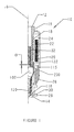
- FIG. 1 shows a portion of a fuel injector 10 in which a needle assembly 100 according to any one of the preferred embodiments of the present invention can be used.
- the fuel injector 10 has an upstream end 12, a downstream end 14, and a longitudinal axis 16 extending therethrough.
- a channel 18 extends longitudinally through the fuel injector 10, within a hollow body 19, along the longitudinal axis 16.
- the hollow body 19 is generally comprised of a generally cylindrical inlet tube 20 located in the channel 18 and a magnetic core 22 which is surrounded by a plastic overmold 24 and which at least partially surrounds the inlet tube 20.
- the hollow body 19 also includes a generally cylindrical non-magnetic shell 26, which is located downstream of the overmold 24.
- the term "downstream" is defined to mean a location toward the bottom of the drawing to which is being referred.
- a generally cylindrical valve body 28 is located downstream of the non-magnetic shell 26.
- a seat 30 is located inside a downstream end of the valve body 28.
- the needle assembly 100 is reciprocably located in the channel 18, downstream of the inlet tube 20. During operation of the fuel injector 10, the needle assembly 100 reciprocably engages and disengages the seat 30, as is well known by those skilled in the art.
- a biasing element preferably a helical spring 32, is located in the inlet tube 20 and biases the needle assembly 100 toward the seat 30.
- the needle assembly 100 has an upstream segment 102, a downstream segment 104, and a longitudinal axis 106, which is co-axial with the fuel injector axis 16.
- the upstream segment 102 and the downstream segment 104 are initially two separate components which are joined together during assembly, as will be described in detail later herein.
- the upstream segment 102 includes a first longitudinal channel 108 which extends therethrough along the longitudinal axis 106.
- the first longitudinal channel 108 has an upstream portion 110 and a downstream portion 112, which is narrower than the upstream portion 110.
- the upstream portion 110 and the downstream portion 112 are connected by an intermediate portion 114, which tapers downward from the upstream portion 110 toward the downstream portion 112.
- the downstream segment 104 includes a second longitudinal channel 116 which, when the upstream segment 102 and the downstream segment 104 are connected, as shown in Fig. 3, is co-axial with the first longitudinal channel 108.
- the outer perimeter of the downstream segment 104 is sized and shaped to fit into the downstream portion of the upstream segment 102 with a slight interference between the upstream and downstream segments 102, 104, respectively.
- the downstream segment 104 is telescopically inserted into the upstream segment 102 a predetermined distance D to obtain a desired overall length of the needle assembly 100.
- the outer perimeter of the upstream segment 102 can be sized and shaped to fit into the upstream portion of the downstream segment 104 so that the upstream segment 102 can be inserted into the downstream segment 104 instead.
- the upstream segment 102 and the downstream segment 104 are connected to each other.
- the connection is formed by welding the upstream segment 102 and the downstream segment 104 together, although those skilled in the art will recognize that other methods, including, but not limited to, furnace brazing, swaging, gluing, interference fit or any other known process to join parts can be sued.
- the predetermined distance D is adjustable between different fuel injector designs without the need to manufacture different sized downstream segments 104, providing for economy in manufacturing.
- the upstream segment 102 and the downstream segment 104 can have different wall thicknesses, such as is shown in Figs. 2 and 3, as required to optimize manufacturing.
- the downstream segment 104 has a generally circular cross-section, those skilled in the art will recognize that the downstream segment 104 can have other shapes as long as the downstream segment 104 can be telescopically inserted into the upstream segment 102. Any space formed between an interior wall of the upstream end 102 and an exterior wall of the downstream end 104 is permissible, as the space allows fuel to flow from the needle assembly 100 toward the seat 30 for injection into the engine (not shown).
- a seating element 118 is fixedly connected to a downstream end of the downstream segment 104 and preferably seals the downstream end of the second longitudinal channel 116.
- the seating element 118 is a generally spherical body, although those skilled in the art will recognize that the seating element can be any other shape, such as a hemisphere, which can seat in the seat 30 when the needle assembly 100 is in the closed position.
- the seating element 118 is welded to the downstream end of the downstream segment 104.
- the seating element 118 is constructed from a corrosion resistant material, such as stainless steel, although those skilled in the art will recognize that other materials can be used.
- At least one generally transverse channel 120 is located in the downstream segment 104.
- the transverse channel 120 communicates the second longitudinal channel 116 with an exterior of the downstream segment 104 such that, during operation of the fuel injector 10, fuel flows downstream through the second longitudinal channel 116, through the at least one transverse channel 120, and out from the needle assembly 100 toward the seat 30 for injection into the engine (not shown).
- the at least one transverse channel 120 is located immediately upstream of the seating element 118, although those skilled in the art will recognize that the at least one transverse channel 120 can be located farther upstream of the seating element 118. Additionally, those skilled in the art will also recognize that the transverse channel 120 can be located in the upstream segment 102, as well.
- either or both of the upstream segment 102 and the downstream segment 104 can be constructed from a non-magnetic corrosion resistant steel, such as SAE 300 series austenitic.
- Each of the upstream segment 102 and the downstream segment 104 can be a tube, a longitudinally welded tube, or a tube formed from a rolled thin sheet. Additionally, those skilled in the art will recognize that the upstream segment 102 and the downstream segment 104 can be formed by other methods as well.
- a magnetic armature 200 is located within the upstream portion of the first longitudinal channel 108, upstream of the generally transverse channel 120.
- the armature 200 is constructed from a magnetic, corrosion resistant steel, such as 430 FR annealed solenoid quality steel, although those skilled in the art will recognize that other materials can be used instead.
- the armature 200 includes a central opening or passage 202 therethrough which communicates the first longitudinal channel 108 upstream of the armature 200 with the first longitudinal channel 108 downstream of the armature 200.
- the armature 200 is generally annular, with the passage 202 along the longitudinal axis 106. Alternatively, as shown in Figs.
- armatures 210, 220, 230, 240, 250, 260 can be other than annularly shaped, such as a parallelogram, triangular, splined, polygonal, with openings 212, 224, 234, 244, 254, 264 between the armature 210, 220, 230, 240, 250, 260 and the interior of the upstream segment 102 which defines the first longitudinal channel 108 through which fuel can flow during operation of the fuel injector 10.
- the armature 200 is connected to the interior of the upstream section 102 which forms the first longitudinal channel 108 with a weld 201.
- other methods of permanently fixing the armature 200 in the upstream segment 102 include furnace brazing, swaging, gluing, interference fit, or any other method or process typically used to permanently join the parts.
- the armature 200 is located downstream in the upstream portion 110 of the first longitudinal channel 108 sufficiently so that a guide portion 122 on the interior of the first longitudinal channel 108 is upstream of the armature 200. Additionally, as shown in Fig. 1, a gap G is formed between the armature 20 and the inlet tube 20, providing a space for the armature 200 and the needle assembly 100 to travel during operation, as will be discussed in more detail later herein.
- the guide portion 122 reciprocably engages an exterior portion of the inlet tube 20 such that, as the needle assembly 100 assembly reciprocates along the longitudinal axis 106 during operation of the fuel injector 10, the guide portion 122 slides along the exterior portion of the inlet tube 20 and maintains the alignment of the upstream end 102 of the needle assembly 100 with respect to the longitudinal axis 106.
- the use of the wall of the upstream segment 102 as the guide portion 122 allows for the elimination of a separate upper needle guide which is used in known, prior art fuel injectors.
- an upstream face 204 of the armature 200 includes a metal plated surface.
- the metal plated surface is chrome, although those skilled in the art will recognize that other plating metals can be used.
- the upstream surface 204 can be surface hardened. The purpose of the metal plating or surface hardening is to provide a hardened upstream surface 204 of the armature 200 so that, when the armature 200 contacts the inlet tube 20 during operation of the fuel injector 10, the armature 200 does not wear. Consequently, the armature 200 is simply an annular disk with a hardened upstream surface 204.
- the armature 200 may be only a cylinder with a central opening 202, preferably, the upstream surface 204 of the armature 200 may be a generally frusto-conical surface having at least a slight taper 206 toward the longitudinal axis 106, as shown in the enlargement of a portion of the armature 200 and spring 32 in Fig. 5.
- the tapered portion 206 provides a seating area 208 for the spring 32 to seat on the armature 200.
- the seating area 208 centers the spring 32 within the inlet tube, reducing the likelihood of contact between the spring 32 and the inlet tube 20 during operation of the fuel injector 10, which can cause wear of the spring 32 and/or the inlet tube 20, resulting in premature failure of the fuel injector 10.
- a fuel filter 300 is located in the first longitudinal channel 108, downstream of the armature 200.
- the filter 300 is a flat screen, although those skilled in the art will recognize that other types and shapes of filters, such as conical, can be used.
- the fuel filter 300 can be connected to a downstream face 209 of the armature 200, such as by welding, and the armature 200 and filter 300 can be installed in the first longitudinal channel 108.
- the fuel filter 300 can be installed in the first longitudinal channel 108, and then the armature 200 can be installed on top of the filter 300.
- the location of the filter 300 in the first longitudinal channel 108, downstream of the armature 200 provides a more efficient filtering capability than known prior art fuel injectors which employ a fuel filter at the upstream end of the injector.
- the filter 300 is located immediately downstream of the armature 200, those skilled in the art will recognize that a first alternate filter 310 can be spaced from the armature 200, as shown in Fig. 6, or that a second alternate filter 320 can be located in the downstream segment 104, as shown in Fig. 7.
- the needle 400 is a single, generally cylindrical shell 402 defining a longitudinal channel 404.
- the shell 402 includes a first, upstream segment 408 having an upstream channel 410 defining a first cross-sectional area and a second, downstream segment 412 having a downstream channel 414 defining a second cross-sectional area, which is smaller than the first cross-sectional area.
- a transitional segment 416 connects the upstream segment 408 and the downstream segment 412, and provides a constantly decreasing cross-sectional channel area between the upstream segment 408 and the downstream segment 412.
- the transitional segment 416 can be omitted and the upstream segment 408 can be directly connected to the downstream segment 412.
- the seating element 118 is fixedly connected to a downstream end of the downstream segment 412 and preferably seals the downstream end of the second longitudinal channel 414, similar to the first embodiment, as described above.
- the seating element 118 is welded to the downstream end of the downstream segment 412.
- At least one transverse channel 416 is located in the downstream segment 412.
- the transverse channel 416 communicates the downstream channel 414 with an exterior of the downstream segment 412 such that, during operation of the fuel injector 10, fuel flows downstream through the downstream channel 414, through the at least one transverse channel 416, and out from the needle 400 toward the seat 30 for injection into the engine.
- the at least one transverse channel 416 is located immediately upstream of the seating element 118, although those skilled in the art will recognize that the at least one transverse channel 416 can be located farther upstream of the seating element 118.
- the filter 300 is located immediately downstream of the armature 200, although those skilled in the art will recognize that the filters 310, 320 can be located in the needle 400 as described above in regard to the needle assembly 100.
- the fuel injector is initially in a closed position.
- the needle assembly 100 is biased downstream by the spring 32, which in turn biases the seating element 118 against the seat 30, sealingly mating the seating element 118 with the seat 30. Fuel is thus precluded from flowing through the injector 10.
- a magnetic coil (not shown) is energized, producing a magnetic force sufficient to overcome the spring 32, drawing the armature 200 upstream, closing the gap G between the armature 200 and the inlet tube 20. Because the armature 200 is fixedly connected to the needle assembly 100, the needle assembly 100 travels upstream with the armature 200, and the seating element 118 is lifted from the seat 30, providing a fluid flow path for the fuel to flow through the injector 10.
- the fuel flows downstream from the fuel injector inlet (not shown), through the inlet tube 20 and around the spring 32 to the armature 200.
- the fuel flows through the central opening 202 in the armature 200 and through any openings between the armature 200 and the needle assembly 100.
- the fuel then flows through the fuel filter 300 and through the longitudinal channel 108.
- the fuel then flows through the at least one transverse channel 120 and between the seating element 118 and the seat 30, through the seat 30, and out the downstream end 14 of the injector 10.
Landscapes
- Engineering & Computer Science (AREA)
- Chemical & Material Sciences (AREA)
- Combustion & Propulsion (AREA)
- Mechanical Engineering (AREA)
- General Engineering & Computer Science (AREA)
- Physics & Mathematics (AREA)
- Electromagnetism (AREA)
- Manufacturing & Machinery (AREA)
- Fuel-Injection Apparatus (AREA)
Abstract
Description
Claims (27)
- A fuel injector comprising:a hollow body having an upstream segment and a downstream segment; anda valve having:a needle assembly reciprocably mounted in the hollow body, the needle assembly including:andan upstream segment having:a first longitudinal channel extending therethrough; anda magnetic armature located within the first longitudinal channel, the armature including a passage extending therethrough; anda downstream segment having:a second longitudinal channel co-axial with and communicating with the first longitudinal channel, the second longitudinal channel extending therethrough;a seating body located at a downstream end of the downstream segment; anda transverse passage located upstream of the seating body, the transverse passage communicating with at least one of the first and the second longitudinal channels;a seat disposed downstream of the needle, the seating body being adapted to sealingly mate with the seat when the needle is in a closed position.
- The fuel injector according to claim 1, wherein the upstream segment and the downstream segment are non-magnetic.
- The fuel injector according to claim 1, further comprising a filter in the first longitudinal channel downstream of the armature.
- The fuel injector according to claim 1, wherein the downstream segment is connected to the upstream segment with a telescopic connection.
- The fuel injector according to claim 4, wherein the telescopic connection is adjustable between the upstream segment and the downstream segment.
- The fuel injector according to claim 4, wherein the downstream segment is telescopically connected to the upstream segment with an interference fit.
- The fuel injector according to claim 1, further comprising at least one longitudinal passage formed by the armature and the upstream segment.
- The fuel injector according to claim 1, wherein the armature further comprises a generally frusto-conical upstream surface tapering downstream toward the first longitudinal channel.
- The fuel injector according to claim 1, wherein the upstream segment and the downstream segment are of unitary construction.
- The fuel injector according to claim 1, wherein the upstream segment further comprises an interior guide surface upstream of the armature.
- The fuel injector according to claim 1, wherein an upstream portion of the first longitudinal channel is sized to accept a portion of an inlet tube therein.
- The fuel injector according to claim 1, wherein the seating body is a sphere.
- A needle assembly for a fuel injector comprising:an upstream segment having:a first longitudinal channel extending therethrough; anda magnetic armature located within the first longitudinal channel, the armature including a passage extending therethrough; and a downstream segment having:a second longitudinal channel co-axial with and communicating with the first longitudinal channel, the second longitudinal channel extending therethrough;a seating body located at a downstream end of the downstream segment; anda transverse passage located upstream of the seating body, the transverse passage communicating with at least one of the first and the second longitudinal channels.
- The needle assembly according to claim 13, wherein the upstream segment and the downstream segment are non-magnetic.
- The needle assembly according to claim 13, further comprising a filter in the first longitudinal channel downstream of the armature.
- The needle assembly according to claim 13, wherein the downstream segment is connected to the upstream segment with a telescopic connection.
- The needle assembly according to claim 16, wherein the telescopic connection is adjustable between the upstream segment and the downstream segment.
- The needle assembly according to claim 16, wherein the downstream segment is telescopically connected to the upstream segment with an interference fit.
- The needle assembly according to claim 13, further comprising at least one longitudinal passage formed by the armature and the upstream segment.
- The needle assembly according to claim 13, wherein the armature further comprises a generally frusto-conical upstream surface tapering downstream toward the first longitudinal channel.
- The needle assembly according to claim 13, wherein the upstream segment and the downstream segment are of unitary construction.
- The needle assembly according to claim 13, wherein the upstream segment further comprises an interior guide surface upstream of the armature.
- The needle assembly according to claim 13, wherein an upstream portion of the first longitudinal channel is sized to accept a portion of an inlet tube therein.
- The needle assembly according to claim 13, wherein the seating body is a sphere.
- A method of fabricating a needle assembly for a fuel injector comprising:providing an upstream segment having a first longitudinal channel extending therethrough;providing a downstream segment having a second longitudinal channel extending therethrough, the downstream segment further having a seating surface and a transverse opening extending therethrough upstream from the seating surface;aligning the first longitudinal channel co-axially with the second longitudinal channel;inserting one of the upstream segment and the downstream segment into the other of the upstream segment and the downstream segment; andfixedly connecting the upstream segment and the downstream segment.
- The method according to claim 25, further comprising inserting a magnetic armature into the first longitudinal channel.
- The method according to claim 25, further comprising inserting a filter in the first longitudinal channel.
Applications Claiming Priority (2)
| Application Number | Priority Date | Filing Date | Title |
|---|---|---|---|
| US09/606,687 US6409101B1 (en) | 2000-06-30 | 2000-06-30 | Hollow oversized telescopic needle with armature |
| US606687 | 2000-06-30 |
Publications (3)
| Publication Number | Publication Date |
|---|---|
| EP1167750A2 true EP1167750A2 (en) | 2002-01-02 |
| EP1167750A3 EP1167750A3 (en) | 2003-11-05 |
| EP1167750B1 EP1167750B1 (en) | 2008-08-13 |
Family
ID=24429034
Family Applications (1)
| Application Number | Title | Priority Date | Filing Date |
|---|---|---|---|
| EP01202462A Expired - Lifetime EP1167750B1 (en) | 2000-06-30 | 2001-06-26 | Hollow oversized telescopic needle with armature, for a fuel injector |
Country Status (4)
| Country | Link |
|---|---|
| US (1) | US6409101B1 (en) |
| EP (1) | EP1167750B1 (en) |
| JP (1) | JP2002031011A (en) |
| DE (1) | DE60135275D1 (en) |
Families Citing this family (14)
| Publication number | Priority date | Publication date | Assignee | Title |
|---|---|---|---|---|
| US6758421B1 (en) * | 2000-03-31 | 2004-07-06 | Siemens Automotive Corporation | Double concentric inlet tube for setting armature/needle lift and method of manufacturing same |
| US6481646B1 (en) * | 2000-09-18 | 2002-11-19 | Siemens Automotive Corporation | Solenoid actuated fuel injector |
| US7458530B2 (en) * | 2001-10-05 | 2008-12-02 | Continental Automotive Systems Us, Inc. | Fuel injector sleeve armature |
| JP3945357B2 (en) * | 2002-09-18 | 2007-07-18 | 株式会社デンソー | Fuel injection device |
| JP4045209B2 (en) * | 2003-06-20 | 2008-02-13 | 株式会社日立製作所 | Electromagnetic fuel injection valve |
| DE102004033280A1 (en) * | 2004-07-09 | 2006-02-02 | Robert Bosch Gmbh | Injector for fuel injection |
| JP2006233887A (en) * | 2005-02-25 | 2006-09-07 | Denso Corp | Fuel injection valve |
| JP2009174423A (en) * | 2008-01-24 | 2009-08-06 | Hitachi Ltd | Fuel injection valve |
| JP5851086B2 (en) * | 2010-07-05 | 2016-02-03 | 株式会社ニフコ | Mounting member |
| JP5563391B2 (en) * | 2010-07-05 | 2014-07-30 | 株式会社日本自動車部品総合研究所 | solenoid valve |
| CN113660977B (en) | 2019-03-29 | 2024-12-17 | 心脏起搏器股份公司 | Systems and methods for treating cardiac arrhythmias |
| WO2020205397A1 (en) | 2019-03-29 | 2020-10-08 | Cardiac Pacemakers, Inc. | Systems and methods for treating cardiac arrhythmias |
| WO2021050685A1 (en) | 2019-09-11 | 2021-03-18 | Cardiac Pacemakers, Inc. | Tools and systems for implanting and/or retrieving a leadless cardiac pacing device with helix fixation |
| US11510697B2 (en) | 2019-09-11 | 2022-11-29 | Cardiac Pacemakers, Inc. | Tools and systems for implanting and/or retrieving a leadless cardiac pacing device with helix fixation |
Family Cites Families (20)
| Publication number | Priority date | Publication date | Assignee | Title |
|---|---|---|---|---|
| GB1076184A (en) * | 1963-05-01 | 1967-07-19 | Ass Eng Ltd | Fuel injectors for internal combustion engines |
| US4384681A (en) * | 1978-11-01 | 1983-05-24 | The Bendix Corporation | Electromagnetic fuel injector |
| JPS60169665A (en) * | 1984-02-13 | 1985-09-03 | Nippon Denso Co Ltd | Elecromagnetic fuel injection valve |
| JPH0697020B2 (en) * | 1986-10-08 | 1994-11-30 | 三菱自動車工業株式会社 | Injector |
| DE3825134A1 (en) | 1988-07-23 | 1990-01-25 | Bosch Gmbh Robert | ELECTROMAGNETICALLY ACTUABLE VALVE AND METHOD FOR THE PRODUCTION THEREOF |
| US4946107A (en) * | 1988-11-29 | 1990-08-07 | Pacer Industries, Inc. | Electromagnetic fuel injection valve |
| DE3914486A1 (en) | 1989-05-02 | 1990-11-08 | Bosch Gmbh Robert | METHOD FOR PRODUCING A VALVE NEEDLE AND VALVE NEEDLE |
| DE3927932A1 (en) | 1989-08-24 | 1991-02-28 | Bosch Gmbh Robert | ELECTROMAGNETICALLY ACTUABLE FUEL INJECTION VALVE |
| CN1049951C (en) * | 1993-12-09 | 2000-03-01 | 罗伯特·博施有限公司 | Electromagnetic valve |
| JPH07263224A (en) * | 1994-03-25 | 1995-10-13 | Honda Lock Mfg Co Ltd | Solenoid unit and solenoid valve |
| DE4420176A1 (en) | 1994-06-09 | 1995-12-14 | Bosch Gmbh Robert | Valve needle for an electromagnetically actuated valve |
| US5494225A (en) * | 1994-08-18 | 1996-02-27 | Siemens Automotive Corporation | Shell component to protect injector from corrosion |
| US5462231A (en) * | 1994-08-18 | 1995-10-31 | Siemens Automotive L.P. | Coil for small diameter welded fuel injector |
| US5494223A (en) * | 1994-08-18 | 1996-02-27 | Siemens Automotive L.P. | Fuel injector having improved parallelism of impacting armature surface to impacted stop surface |
| JPH0874699A (en) | 1994-09-09 | 1996-03-19 | Zexel Corp | Fuel injection valve |
| DE19532865A1 (en) | 1995-09-06 | 1997-03-13 | Bosch Gmbh Robert | Fuel injector |
| DE19627939C1 (en) | 1996-07-11 | 1997-03-20 | Bosch Gmbh Robert | Solenoid-operated needle valve |
| DE19632196B4 (en) | 1996-08-09 | 2004-11-04 | Robert Bosch Gmbh | Electromagnetically actuated valve |
| DE19638201B4 (en) * | 1996-09-19 | 2005-05-04 | Robert Bosch Gmbh | Fuel injector |
| DE19712590A1 (en) | 1997-03-26 | 1998-10-01 | Bosch Gmbh Robert | Electromagnetically actuated valve |
-
2000
- 2000-06-30 US US09/606,687 patent/US6409101B1/en not_active Expired - Fee Related
-
2001
- 2001-06-26 EP EP01202462A patent/EP1167750B1/en not_active Expired - Lifetime
- 2001-06-26 DE DE60135275T patent/DE60135275D1/en not_active Expired - Lifetime
- 2001-06-29 JP JP2001198862A patent/JP2002031011A/en not_active Ceased
Also Published As
| Publication number | Publication date |
|---|---|
| US6409101B1 (en) | 2002-06-25 |
| JP2002031011A (en) | 2002-01-31 |
| EP1167750B1 (en) | 2008-08-13 |
| EP1167750A3 (en) | 2003-11-05 |
| DE60135275D1 (en) | 2008-09-25 |
Similar Documents
| Publication | Publication Date | Title |
|---|---|---|
| US6409101B1 (en) | Hollow oversized telescopic needle with armature | |
| EP0944769B1 (en) | Fuel injection valve | |
| US6145761A (en) | Fuel injection valve | |
| US6089475A (en) | Electromagnetically operated valve | |
| RU2177075C2 (en) | Electromagnetically operated valve | |
| JP3734702B2 (en) | Electromagnetic fuel injection valve | |
| EP0796393B1 (en) | Electromagnetically operable valve, especially fuel injection valve | |
| JPH09503267A (en) | Valve needle used in electromagnetically actuated valves and method for manufacturing the valve needle | |
| EP1114249B1 (en) | Fuel injection valve | |
| JP2003506626A (en) | Fuel injection valve and method for manufacturing a discharge opening of the valve | |
| EP1055812B1 (en) | Compressed natural gas fuel injector | |
| EP1059438A2 (en) | Fuel injector with tubular lower needle guide | |
| US20020100821A1 (en) | Fuel injection valve | |
| US20100287774A1 (en) | Injector Seat that Includes a Coined Seal Band With Radius | |
| DE3925212A1 (en) | EM fuel injection valve for external ignition Diesel engine - has hollow magnetic armature with recess supporting flange of coupling tube | |
| JPH10274129A (en) | Fuel injection valve | |
| US20050040259A1 (en) | Fuel injector with a deep pocket seat and method of maintaining spatial orientation | |
| JP4469502B2 (en) | Fuel injection valve | |
| EP1200729B1 (en) | Method for adjusting the valve lift of an injection valve | |
| US7341204B2 (en) | Fuel injection valve | |
| US20200109688A1 (en) | Fuel-injection valve | |
| EP2212543B1 (en) | Fuel injection valve | |
| JP3819741B2 (en) | Electromagnetic fuel injection valve | |
| US20010015418A1 (en) | Electromagnetically actuated valve | |
| US7552880B2 (en) | Fuel injector with a deep-drawn thin shell connector member and method of connecting components |
Legal Events
| Date | Code | Title | Description |
|---|---|---|---|
| PUAI | Public reference made under article 153(3) epc to a published international application that has entered the european phase |
Free format text: ORIGINAL CODE: 0009012 |
|
| AK | Designated contracting states |
Kind code of ref document: A2 Designated state(s): AT BE CH CY DE DK ES FI FR GB GR IE IT LI LU MC NL PT SE TR |
|
| AX | Request for extension of the european patent |
Free format text: AL;LT;LV;MK;RO;SI |
|
| PUAL | Search report despatched |
Free format text: ORIGINAL CODE: 0009013 |
|
| AK | Designated contracting states |
Kind code of ref document: A3 Designated state(s): AT BE CH CY DE DK ES FI FR GB GR IE IT LI LU MC NL PT SE TR |
|
| AX | Request for extension of the european patent |
Extension state: AL LT LV MK RO SI |
|
| RIC1 | Information provided on ipc code assigned before grant |
Ipc: 7F 02M 61/12 B Ipc: 7F 02M 61/16 B Ipc: 7F 02M 51/06 A |
|
| RAP1 | Party data changed (applicant data changed or rights of an application transferred) |
Owner name: SIEMENS VDO AUTOMOTIVE CORPORATION |
|
| 17P | Request for examination filed |
Effective date: 20031126 |
|
| 17Q | First examination report despatched |
Effective date: 20040204 |
|
| AKX | Designation fees paid |
Designated state(s): DE FR IT |
|
| 17Q | First examination report despatched |
Effective date: 20040204 |
|
| GRAP | Despatch of communication of intention to grant a patent |
Free format text: ORIGINAL CODE: EPIDOSNIGR1 |
|
| GRAS | Grant fee paid |
Free format text: ORIGINAL CODE: EPIDOSNIGR3 |
|
| GRAA | (expected) grant |
Free format text: ORIGINAL CODE: 0009210 |
|
| AK | Designated contracting states |
Kind code of ref document: B1 Designated state(s): DE FR IT |
|
| REF | Corresponds to: |
Ref document number: 60135275 Country of ref document: DE Date of ref document: 20080925 Kind code of ref document: P |
|
| PLBE | No opposition filed within time limit |
Free format text: ORIGINAL CODE: 0009261 |
|
| STAA | Information on the status of an ep patent application or granted ep patent |
Free format text: STATUS: NO OPPOSITION FILED WITHIN TIME LIMIT |
|
| 26N | No opposition filed |
Effective date: 20090514 |
|
| PGFP | Annual fee paid to national office [announced via postgrant information from national office to epo] |
Ref country code: IT Payment date: 20090620 Year of fee payment: 9 |
|
| PG25 | Lapsed in a contracting state [announced via postgrant information from national office to epo] |
Ref country code: IT Free format text: LAPSE BECAUSE OF NON-PAYMENT OF DUE FEES Effective date: 20100626 |
|
| PGFP | Annual fee paid to national office [announced via postgrant information from national office to epo] |
Ref country code: DE Payment date: 20120630 Year of fee payment: 12 |
|
| PGFP | Annual fee paid to national office [announced via postgrant information from national office to epo] |
Ref country code: FR Payment date: 20120705 Year of fee payment: 12 |
|
| REG | Reference to a national code |
Ref country code: FR Ref legal event code: ST Effective date: 20140228 |
|
| REG | Reference to a national code |
Ref country code: DE Ref legal event code: R119 Ref document number: 60135275 Country of ref document: DE Effective date: 20140101 |
|
| PG25 | Lapsed in a contracting state [announced via postgrant information from national office to epo] |
Ref country code: DE Free format text: LAPSE BECAUSE OF NON-PAYMENT OF DUE FEES Effective date: 20140101 |
|
| PG25 | Lapsed in a contracting state [announced via postgrant information from national office to epo] |
Ref country code: FR Free format text: LAPSE BECAUSE OF NON-PAYMENT OF DUE FEES Effective date: 20130701 |