EP1167284A2 - Device for recovery of hydrogen - Google Patents
Device for recovery of hydrogen Download PDFInfo
- Publication number
- EP1167284A2 EP1167284A2 EP01114271A EP01114271A EP1167284A2 EP 1167284 A2 EP1167284 A2 EP 1167284A2 EP 01114271 A EP01114271 A EP 01114271A EP 01114271 A EP01114271 A EP 01114271A EP 1167284 A2 EP1167284 A2 EP 1167284A2
- Authority
- EP
- European Patent Office
- Prior art keywords
- hydrogen
- membrane
- box
- perforated metal
- gas
- Prior art date
- Legal status (The legal status is an assumption and is not a legal conclusion. Google has not performed a legal analysis and makes no representation as to the accuracy of the status listed.)
- Withdrawn
Links
Images

Classifications
-
- C—CHEMISTRY; METALLURGY
- C01—INORGANIC CHEMISTRY
- C01B—NON-METALLIC ELEMENTS; COMPOUNDS THEREOF; METALLOIDS OR COMPOUNDS THEREOF NOT COVERED BY SUBCLASS C01C
- C01B3/00—Hydrogen; Gaseous mixtures containing hydrogen; Separation of hydrogen from mixtures containing it; Purification of hydrogen; Reversible storage of hydrogen
- C01B3/02—Production of hydrogen; Production of gaseous mixtures containing hydrogen
- C01B3/22—Production of hydrogen; Production of gaseous mixtures containing hydrogen by decomposition of gaseous or liquid organic compounds
- C01B3/24—Production of hydrogen; Production of gaseous mixtures containing hydrogen by decomposition of gaseous or liquid organic compounds of hydrocarbons
-
- C—CHEMISTRY; METALLURGY
- C01—INORGANIC CHEMISTRY
- C01B—NON-METALLIC ELEMENTS; COMPOUNDS THEREOF; METALLOIDS OR COMPOUNDS THEREOF NOT COVERED BY SUBCLASS C01C
- C01B3/00—Hydrogen; Gaseous mixtures containing hydrogen; Separation of hydrogen from mixtures containing it; Purification of hydrogen; Reversible storage of hydrogen
- C01B3/50—Separation of hydrogen or hydrogen-containing gases from gaseous mixtures, e.g. purification
- C01B3/501—Separation of hydrogen or hydrogen-containing gases from gaseous mixtures, e.g. purification by diffusion
- C01B3/503—Separation of hydrogen or hydrogen-containing gases from gaseous mixtures, e.g. purification by diffusion characterised by membranes
-
- C—CHEMISTRY; METALLURGY
- C01—INORGANIC CHEMISTRY
- C01B—NON-METALLIC ELEMENTS; COMPOUNDS THEREOF; METALLOIDS OR COMPOUNDS THEREOF NOT COVERED BY SUBCLASS C01C
- C01B2203/00—Integrated processes for the production of hydrogen or synthesis gas
- C01B2203/04—Integrated processes for the production of hydrogen or synthesis gas containing a purification step for the hydrogen or the synthesis gas
- C01B2203/0405—Purification by membrane separation
-
- C—CHEMISTRY; METALLURGY
- C01—INORGANIC CHEMISTRY
- C01B—NON-METALLIC ELEMENTS; COMPOUNDS THEREOF; METALLOIDS OR COMPOUNDS THEREOF NOT COVERED BY SUBCLASS C01C
- C01B2203/00—Integrated processes for the production of hydrogen or synthesis gas
- C01B2203/04—Integrated processes for the production of hydrogen or synthesis gas containing a purification step for the hydrogen or the synthesis gas
- C01B2203/0465—Composition of the impurity
- C01B2203/0475—Composition of the impurity the impurity being carbon dioxide
Definitions
- the present invention relates to a device for recovering hydrogen generated by decomposition of hydrocarbon gas with steam.
- Hydrogen has been used in broad industrial fields as basic raw material in a chemical industry, a fuel for a fuel cell or an atmospheric gas for heat treatment.
- a representative process to cope with a small demand is decomposition of hydrocarbon gas with steam.
- a decomposition product contains CO, CO 2 and residual H 2 O other than H2.
- the product cannot be used as such for a fuel cell due to the inclusions; otherwise faculty of the fuel cell would be degraded.
- a conventional method of removing subspecies uses a hydrogen-permeating membrane made of such a catalytic element as Pd-Ag or Ta selectively permeable to hydrogen.
- the hydrogen-permeating membrane has been formed so far as a thin layer on a heat resistant perforated body, as disclosed in JP 63-294925 A1 and JP 1-164419 A1 .
- Recently, feasibility of a perforated metal body, in which a plurality of holes are formed for passage of hydrogen has been studied instead of a conventional heat-resistant perforated body.
- a perforated metal body coated with a hydrogen-permeating membrane is attached to a surface of a hydrogen-recovering device, to which a takeout pipe is coupled, and embedded in a catalyst layer. Hydrogen gas generated by decomposition of hydrocarbon gas with steam selectively passes through the hydrogen-permeating membrane into the hydrogen-recovering device and flows through the takeout pipe to the outside.
- a conventional hydrogen-recovering device uses a thick plate as a structural member in order to inhibit thermal deformation caused by heat cycles between high and ordinary temperatures. As a result, the device is heavy, and a special fixing jig is necessarily used for fixing the device in a reforming plant at a predetermined position.
- the thick plate is processed by etching, machining or electric discharge machining to form holes for passage of hydrogen and a header, and then a hydrogen-permeating membrane such as a Pd-Ag alloy is laser-welded to an external surface of the thick plate. Such the processing is troublesome and inappropriate for mass-production at a low cost.
- the present invention aims at provision of a new hydrogen-recovering device, which is light and strong, easy to manufacture by using a thin steel sheet press-worked to a predetermined shape as a structural member.
- the present invention proposed a box-shaped or tubular hydrogen-recovering device having a frame made of a ferritic stainless steel.
- the box-shaped hydrogen-recovering has a box-shaped frame made of a stainless steel having a takeout pipe attached to its one side, a plurality of spacers arranged along a lengthwise direction inside said box-shaped frame, perforated metal plates fixed to both surfaces of said box-shaped frame, a hydrogen-permeating membrane clad with a membrane holder fixed to said perforated metal plate, wherein hydrogen gas as a decomposition product of hydrocarbon selectively passes through said hydrogen-permeating membrane and flows to the outside.
- the tubular hydrogen-recovering device comprises a pair of upper and lower discs each of which has an opening for passage of hydrogen at its center, a plurality of reinforcement members which extend between said upper and lower discs and locate with the same intervals along a circumferential direction, perforated metal plates which is fixed to a cylindrical surface defined by curved surfaces and end faces of said reinforcement members and is coated with a hydrogen-permeating membrane, and a takeout pipe coupled to one or both of said upper and lower discs, wherein hydrogen passes through said hydrogen-permeating membrane into a cavity inside said perforated plates and flows through said takeout pipe to the outside.
- the members other than the hydrogen-permeating membrane are preferable made of a ferritic stainless steel, which has a thermal expansion coefficient near that of the hydrogen-permeating membrane.
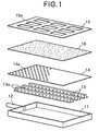
- Fig. 1 is a bird eye's view for explaining fabrication of a box-shaped hydrogen-recovering device.
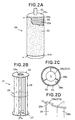
- Fig. 2A is a bird eye's view (a) illustrating a tubular hydrogen-recovering device.
- Fig, 2B is a bird eye's view illustrating a tubular frame.
- Fig. 2C is a horizontal sectional view illustrating the tubular hydrogen-recovering device
- Fig. 2D is a partial view for explaining joining a reinforcement member to an upper or lower disc.
- Fig. 3A is a sectional view illustrating another tubular hydrogen-recovering device.
- Fig. 3B is a partial view for joining a reinforcement member to an upper or lower disc.
- Fig. 3C is a horizontal sectional view illustrating the tubular hydrogen-recovering device
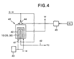
- Fig. 4 is a schematic view illustrating a gas-reforming plant
- a box-shaped hydrogen-recovering device 10 has a box-shaped frame 11, as shown in Fig. 1.
- the frame 11 is fabricated from a stainless steel sheet pressed to a predetermined rectangular shape by welding, as a structural member.
- the box-shaped frame may be a unitary body as shown in Fig. 1 or a body separable to upper and lower parts at a position of a takeout pipe 12.
- the takeout pipe 12 for outflow of hydrogen gas is fixed to one side of the frame 11, a plurality of spacers 13 are arranged inside the frame 11, and a perforated metal plate 14 is put on and fixed to the frame 11.
- a hydrogen separator having a hydrogen-permeating membrane 16 clad with a membrane holder 15 is further fixed to the perforated metal plate 14.
- Another hydrogen separator is attached to an opposite surface of the frame 11 in the same way.
- the hydrogen permeating membrane 16 is a thin film of 5-50 ⁇ m in thickness made of a Pd-20%Ag alloy or Ta selectively permeable to hydrogen.
- the membrane holder 15 as a reinforcement for the membrane 16 is a stainless steel sheet having many openings 15a formed therein.
- the hydrogen-permeating membrane 16 may be fixed to the membrane holder 15 by CO 2 laser-welding, YAG laser-welding, microwave plasma-welding, electron beam-welding or the like.
- a lot of small openings 14a are formed in the metal plate 14, to introduce hydrogen gas, which passes through the hydrogen-permeating membrane 16, to an inner space of the hydrogen-recovering device 10.
- the small openings 14a are preferably of 0.1-1.5mm in diameter so as to avoid lead-in of the hydrogen-permeating membrane 16 inside the device 10 without increase of resistance against flow of hydrogen gas.
- the small openings 14a are preferably formed in the metal plate 14 at an area ratio of 10% or more based on a surface of the hydrogen-permeating membrane 16, in order to efficiently absorb hydrogen gas, which is generated by decomposition of hydrocarbon gas with steam, in the device 10.
- the small openings 14a of such diameter may be formed by electron beam-machining or chemical etching.
- a metal sheet having openings of predetermined diameter formed by punching can be used as the perforated metal plate 14.
- the spacers 13 are arranged inside the box-shaped frame 11 along a lengthwise direction of the device 10.
- the spacers 13 support the hydrogen-permeating membrane 16 and also define a passage of hydrogen gas, which is absorbed in the device 10, leading to the takeout pipe 12.
- the spacers 13 are made from a stainless steel sheet shaped to a C-shaped cross section. A plurality of holes 13a for passage of hydrogen gas are formed at side faces of the spacers 13.
- the hydrogen-permeating membrane 16 is firmly fixed to the box-shaped frame 11 in a state reinforced with the membrane holder 15, the perforated metal plate 14 and the spacers 13. Due to such supporting members, the hydrogen-permeating membrane 16 sufficiently resists to deformation or damage caused by thermal stress, when the hydrogen-recovering device 10 is installed in a gas-reforming plant exposed to heat cycles of heating and cooling. Therefore, the membrane 16 maintains its selective hydrogen-permeability at a high level over a long term.
- a tubular hydrogen-recovering device 20 has a tubular frame 21, as shown in Fig. 2B. which is fabricated by press working and welding a stainless steel sheet, as a structural member.
- Caps 24u and 24d are attached to a top and a bottom of the tubular frame 21.
- a takeout pipe 25 is coupled to the upper cap 24u, to take out hydrogen gas, which passes through the hydrogen-permeating membrane 23 into the device 20.
- the takeout pipe 25 may be coupled to the lower cap 24d or to both of the caps 24u and 24d.
- the hydrogen-permeating membrane 23 is the same film as the hydrogen-permeating membrane 16 shown in Fig. 1.
- the perforated metal plate 22 is made of a stainless steel or the like excellent in heat resistance for reinforcement of the hydrogen-permeating membrane 23.
- the perforated metal plate 22 made of a stainless steel has nearly the same thermal expansion coefficient as that of the hydrogen-permeating membrane 23, so that the hydrogen-permeating membrane 23 is prevented from peeling off caused by heat cycles of heating and cooling.
- the metal plate 22 has small openings 22a for introducing hydrogen, which passes through the hydrogen-permeating membrane 23, into the device 20.
- the small openings 22a are preferably of 0.1-1.5mm in diameter so as to avoid lead-in of the hydrogen-permeating membrane 23 inside the hydrogen-recovering device 20 without increase of resistance against flow of hydrogen gas.
- the small openings 22a are preferably formed in the metal plate 22 at an area ratio of 10% or more based on a surface of the hydrogen-permeating membrane 23 .
- the small openings 22a of such diameter may be formed by electron beam-machining or chemical etching. Of course, a metal sheet having openings of predetermined diameter formed by punching can be used as the perforated metal plate 22.
- the tubular frame 21 has an upper disc 26 and a lower disc 27, between which a plurality of reinforcement members 28 are extended, as shown in Fig. 2B.
- the upper disc 26, the lower disc 27 and the reinforcement members 28 are preferably made of a stainless steel good of heat resistance and high-temperature strength.
- Openings 26a and 27a for passage of hydrogen are formed in the upper disc 16 and the lower disc 27, respectively, at their centers.
- Notched parts 26b and 27b for insertion of top and bottom ends of the reinforcement members 28 are formed with the same intervals along the circumferences of the upper disc 26 and the lower disc 27, respectively, as shown in Fig. 2D.
- Each reinforcement member 28 has a curved part 28a matching to a periphery of the upper disc 26 or the lower disc 27 and an inward part 28b bent with a right angle from the curved part 28a. That is, the reinforcement member 28 has an L-shaped cross section composed of the curved part 28a and the inward part 28b, so as to enhance its deformation resistance along a circumferential direction.
- the curved part 28a and the inward part 28b are partially cut off with a length corresponding to thickness of the discs 26 and 27 at the top and the bottom of the reinforcement member 28, to form projections 28c.
- the inward parts 28b direct to a center of the tubular frame 21, and the curved parts 28a compose parts of the cylindrical surface. Since a plurality of the reinforcement members 28 are installed between the upper disc 26 and the lower disc 27 with the same intervals along the circumferential direction, the tubular frame 21 is fabricated in a state good of strength and sufficiently resistant to deformation caused by vertical and circumferential stresses. In case of a long tubular frame 21, one or more intermediate discs 29 (shown in Fig. 2B) having the same configuration as the discs 26, 27 may be interposed between the upper disc 26 and the lower disc 27, in order to surely protect the reinforcement members 28 from deformation for maintenance of a predetermined space for passage of hydrogen gas.
- An upper cap 24d and a lower cap 24u, to which a takeout pipe 25 is coupled are attached to the tubular frame 21.
- a perforated metal plate 22, on which the hydrogen-permeating membrane 23 is laminated, is fixed to a cylindrical surface defined by the curved parts 28a of the reinforcement members 28.
- the perforated metal plate 22 is seam-welded to the caps 24u and 24d at positions w .
- the perforated metal plate 22 may be optionally spot-welded to the curved parts 28a of the reinforcement members 28, the upper disc 26 and the lower disc 27. Accounting welding operation, the perforated metal plate 22 has preferably upper and lower parts 22b without the small openings 22a.
- the hydrogen-recovering device 20 fabricated in this way is light and strong. Since the device 20 is reinforced with a plurality of the members 28, a space S for passage of hydrogen gas is assured inside the device 20. The perforated metal plate 22 is supported by the reinforcement members 28 from the inside. Therefore, the device 20 exhibits excellent deformation resistance against thermal stress and maintains selective hydrogen-permeability at a high level without deformation or damage, when it is installed in a gas-reforming plant driven with heat cycles of heating and cooling.
- a perforated metal plate 32 may be supported by sides of reinforcement members 38, as shown in Fig. 3C .
- a plurality of the reinforcement members 38 extend between an upper disc 36 and a lower disc 37, in the manner such that a side face 38d of each reinforcement member 38 locates at peripheries of the discs 36 and 37.
- Each of the upper disc 36 and the lower disc 37 has the configuration that a flange 36d, 37d stands up on a bottom 36c, 37c at its periphery.
- An opening 36a, 37a for passage of hydrogen gas is formed in the bottom 36c, 37c at its center, as shown in Fig. 3B.
- Notched parts 36e, 37e, which extend from the periphery of the bottom 36c, 37c to the opening 36e, 37e, are formed in the bottom 36c, 37c.
- An L-shaped reinforcement member 38 has top and bottom ends inserted into the notched parts 36e, 37e.
- the side face 38d of the reinforcement member 38 is preferably stepped at its upper and lower parts 38e, to facilitate positioning of the reinforcement member 38 to the upper disc 36 and the lower disc 37.
- the hydrogen-recovering device 30 shown in Fig. 3A has the structure that perforated metal plates 32, on which the hydrogen-permeating membrane 33 is laminated, is supported with the side faces 38d of the reinforcement members 38.
- Such the structure enables decrease of the small openings 32a in number plugged with the reinforcement members 38 and so broadens an effective surface area of the hydrogen-permeating membrane 33.
- the reinforcement member 38 is also improved in rigidity due to the bent part 38f. Therefore, when the device 30 installed in a gas-reforming plant is exposed to heat cycles of heating and cooling during recovery of hydrogen gas, the perforated metal plate 32 is prevented from deformation or damage so as to assure a predetermined space S for passage of hydrogen gas, as shown in Fig. 3C.
- any of the hydrogen-recovering devices 10, 20 and 30 is light and strong, so that it can be installed in a gas-reforming plant 40 without use of such a fixing jig as in case of a conventional hydrogen-recovering device, as shown in Fig. 4..
- the takeout pipe 12 is coupled to an opening 41 of the gas-reforming plant 40.
- a cavity of the gas-reforming plant 40 is filled with a reforming catalyst 42 such as a Ni catalyst supported with alumina.
- Omission of any fixing jig for installation of the hydrogen-recovering device 10 ( 20 or 30 ) means that a ratio of an inner space of the gas-reforming plant 40 occupied by the device 10 ( 20 or 30 ) is made smaller, so that a big amount of the catalyst 42 can be put in the gas-reforming plant 40 to enhance an efficiency of hydrocarbon-decomposing reaction.
- Hydrocarbon gas G such as city gas is fed together with steam V generated by a boiler 43 into the gas-reforming plant 40 receiving the hydrogen-recovering device 10 ( 20 or 30 ) and the catalyst 42 therein.
- H 2 as a decomposition product selectively passes through the hydrogen-permeating membrane 16 ( 23 ) into the hydrogen-recovering device 10 ( 20 or 30 ), and flows out through the takeout pipe 42. Waste gas W other than H 2 is discharged through an exhaust pipe to the outside.
- An atmospheric pressure in the hydrogen-recovering device 10 ( 20 or 30 ) is preferably controlled at a value lower by 0.1-1MPa than that of the gas-reforming plant 40 , in order to effectively introduce hydrogen gas as a decomposition product into the hydrogen-recovering device 10 ( 20 or 30 ). That is, an inner space of the hydrogen-recovering device 10 ( 20 or 30 ) is preferably held in a decompressed state, to increase a flow amount of hydrogen gas selectively passing through the hydrogen-permeating membrane 16 ( 23 ) for further acceleration of the hydrocarbon-decomposing reaction.
- the hydrogen-recovering device 10 ( 20 or 30 ) is prevented from deformation regardless application of the pressure difference, since the hydrogen-permeating membrane 16 ( 23 ) is supported with the membrane holder 16, the perforated metal plate 14 and the spacers 13 or with the reinforcement members 28 ( 38 ).
- the box-shaped hydrogen-recovering device newly proposed by the present invention has the structure that a hydrogen-permeating membrane is clad with a membrane holder and fixed to spacers and a perforated metal plate of a box-shaped frame.
- the tubular hydrogen-recovering device has the structure that a hydrogen-permeating membrane is supported with a perforated metal plate. Due to the structure, any of the devices is light and strong, so that it can be installed in a gas-reforming plant without use of a fixing jig.
- Omission of a fixing jig means that a ratio of an inner space of the gas-reforming plant occupied by the device is made smaller, so that a big amount of a catalyst can be put in the gas-reforming plant to enhance an efficiency of a reforming reaction.
- the device also maintains its original shape without deformation, even when its internal pressure is differentiated from a pressure of the gas-reforming plant to promote outflow of hydrogen gas.
Landscapes
- Chemical & Material Sciences (AREA)
- Organic Chemistry (AREA)
- Engineering & Computer Science (AREA)
- Combustion & Propulsion (AREA)
- Inorganic Chemistry (AREA)
- Health & Medical Sciences (AREA)
- General Health & Medical Sciences (AREA)
- Hydrogen, Water And Hydrids (AREA)
- Separation Using Semi-Permeable Membranes (AREA)
Abstract
Description
Claims (4)
- A box-shaped device for recovery of hydrogen gas generated by decomposition of hydrocarbon, which comprises:wherein hydrogen gas selectively passes through said hydrogen-permeating membrane and flows through said takeout pipe to the outside.a box-shaped frame made of stainless steel having a takeout pipe attached to its one side;a plurality of spacers arranged along a lengthwise direction inside said box-shaped frame;perforated metal plates fixed to both surfaces of said box-shaped frame;a hydrogen-permeating membrane clad with a membrane holder fixed to each of said perforated metal plates,
- The tubular device defined in Claim 1, wherein the spacers and the perforated metal plate are made of ferritic stainless steel.
- A tubular device for recovery of hydrogen gas generated by decomposition of hydrocarbon, which comprises:wherein hydrogen selectively passes through said hydrogen-permeating membrane into a cavity inside said perforated plates and flows through said takeout pipe to the outside.a pair of upper and lower discs each of which has an opening for passage of hydrogen at its center;a plurality of reinforcement members, which extend between said upper and lower discs and locate with the same intervals along a circumferential direction;perforated metal plates, each of which is fixed to a cylindrical surface defined by curved surfaces and end faces of said reinforcement members and is coated with a hydrogen-permeating membrane; anda takeout pipe coupled to one or both of said upper and lower discs;
- The tubular device defined in Claim 3, wherein the upper and lower discs, the reinforcement members and the perforated plates are made of ferritic stainless steeL
Applications Claiming Priority (4)
| Application Number | Priority Date | Filing Date | Title |
|---|---|---|---|
| JP2000192048 | 2000-06-27 | ||
| JP2000192049 | 2000-06-27 | ||
| JP2000192048A JP2002012409A (en) | 2000-06-27 | 2000-06-27 | Box-type hydrogen recovery device |
| JP2000192049A JP3904809B2 (en) | 2000-06-27 | 2000-06-27 | Cylindrical hydrogen recovery system |
Publications (2)
| Publication Number | Publication Date |
|---|---|
| EP1167284A2 true EP1167284A2 (en) | 2002-01-02 |
| EP1167284A3 EP1167284A3 (en) | 2004-06-16 |
Family
ID=26594722
Family Applications (1)
| Application Number | Title | Priority Date | Filing Date |
|---|---|---|---|
| EP01114271A Withdrawn EP1167284A3 (en) | 2000-06-27 | 2001-06-12 | Device for recovery of hydrogen |
Country Status (5)
| Country | Link |
|---|---|
| US (1) | US6527832B2 (en) |
| EP (1) | EP1167284A3 (en) |
| KR (1) | KR20020000833A (en) |
| AU (1) | AU781948B2 (en) |
| CA (1) | CA2351873A1 (en) |
Cited By (1)
| Publication number | Priority date | Publication date | Assignee | Title |
|---|---|---|---|---|
| WO2010128374A1 (en) * | 2009-05-05 | 2010-11-11 | Genesis Fueltech, Inc. | Hydrogen purifier module with membrane support |
Families Citing this family (17)
| Publication number | Priority date | Publication date | Assignee | Title |
|---|---|---|---|---|
| US7195663B2 (en) * | 1996-10-30 | 2007-03-27 | Idatech, Llc | Hydrogen purification membranes, components and fuel processing systems containing the same |
| DE60113596T2 (en) * | 2000-06-27 | 2006-06-22 | Nisshin Steel Co., Ltd. | Gas reformer for the recovery of hydrogen |
| EP1433521A4 (en) * | 2001-09-26 | 2006-04-12 | Toyo Kohan Co Ltd | GAS SEPARATION UNIT AND METHOD FOR MANUFACTURING THE SAME |
| US7115148B2 (en) * | 2002-05-14 | 2006-10-03 | Her Majesty The Queen In Right Of Canada, As Respresented By The Minister Of Defence Of Her Majesty's Canadian Government | Compact methanol steam reformer with integrated hydrogen separation |
| DE10235419B4 (en) * | 2002-08-02 | 2005-02-10 | Daimlerchrysler Ag | Membrane module for hydrogen separation and process for its preparation |
| US7537738B2 (en) * | 2003-01-21 | 2009-05-26 | Gm Global Technology Operations, Inc. | Fuel processing system having a membrane separator |
| US8002853B2 (en) * | 2003-07-29 | 2011-08-23 | Societe Bic | Hydrogen-generating fuel cell cartridges |
| JP4622383B2 (en) * | 2004-08-18 | 2011-02-02 | トヨタ自動車株式会社 | Hydrogen separation substrate |
| MX2007012436A (en) * | 2005-04-06 | 2007-12-05 | Cabot Corp | Method to produce hydrogen or synthesis gas. |
| US7914611B2 (en) * | 2006-05-11 | 2011-03-29 | Kci Licensing, Inc. | Multi-layered support system |
| JP4792598B2 (en) * | 2008-03-24 | 2011-10-12 | 株式会社日本製鋼所 | Hydrogen permeation module and method of use thereof |
| PL2352403T3 (en) * | 2008-11-19 | 2014-07-31 | Huntleigh Technology Ltd | Multi-layered support system |
| US8918930B2 (en) | 2011-01-04 | 2014-12-30 | Huntleigh Technology Limited | Methods and apparatuses for low-air-loss (LAL) coverlets and airflow units for coverlets |
| AU2012286707B2 (en) | 2011-07-28 | 2017-04-06 | Arjo Ip Holding Ab | Multi-layered support system |
| US9326903B2 (en) | 2011-10-03 | 2016-05-03 | Huntleigh Technology Limited | Multi-layered support system |
| KR101283326B1 (en) * | 2011-10-31 | 2013-07-09 | 한국에너지기술연구원 | Module configuration of hydrogen purification separation membrane module which have mixing part |
| US20130212808A1 (en) | 2012-02-21 | 2013-08-22 | Charles A. Lachenbruch | Topper with Targeted Fluid Flow Distribution |
Family Cites Families (24)
| Publication number | Priority date | Publication date | Assignee | Title |
|---|---|---|---|---|
| US2824620A (en) * | 1955-09-12 | 1958-02-25 | Universal Oil Prod Co | Purification of hydrogen utilizing hydrogen-permeable membranes |
| FR1255382A (en) * | 1960-01-23 | 1961-03-10 | Commissariat Energie Atomique | Improvements to methods and devices for coating a macroporous metal support with a microporous metal layer |
| US3148031A (en) * | 1961-02-08 | 1964-09-08 | Union Carbide Corp | Method for separating and purifying hydrogen by permeation |
| DE1212049B (en) * | 1961-07-15 | 1966-03-10 | Robert V Linde | Diffusion cell for the separation of pure hydrogen from gas mixtures |
| US3238704A (en) * | 1963-03-07 | 1966-03-08 | Engelhard Ind Inc | Diffusion purification of gases |
| US3336730A (en) * | 1964-11-17 | 1967-08-22 | Union Carbide Corp | Hydrogen continuous production method and apparatus |
| US3469372A (en) * | 1965-06-18 | 1969-09-30 | Mitsubishi Gas Chemical Co | Hydrogen permeable membrane and hydrogen permeating assembly |
| US3447288A (en) * | 1965-08-23 | 1969-06-03 | Prototeck Inc | Gas-diffusion assembly including thin hydrogen-permeable impervious foil |
| DE3332348A1 (en) * | 1983-09-08 | 1985-04-04 | Kernforschungsanlage Jülich GmbH, 5170 Jülich | HYDROGEN PERMEATION WALL |
| DE3421833A1 (en) * | 1984-06-13 | 1985-12-19 | Battelle-Institut E.V., 6000 Frankfurt | Membrane for separating off gases from gas mixtures and process for the production thereof |
| DE3424208A1 (en) * | 1984-06-30 | 1986-01-16 | Kernforschungsanlage Jülich GmbH, 5170 Jülich | METHOD AND DEVICE FOR INCREASING THE SALES OF GAS REACTIONS PROCESSING WITH HYDROGEN PRODUCTION |
| JPS61278328A (en) * | 1985-06-04 | 1986-12-09 | Matsushita Electric Ind Co Ltd | Gas permeable membrane module |
| JPS62102814A (en) * | 1985-10-30 | 1987-05-13 | Matsushita Electric Ind Co Ltd | Gas permeable membrane cell |
| JPS63258619A (en) * | 1987-04-16 | 1988-10-26 | Kawasaki Heavy Ind Ltd | Gas permselective membrane module |
| JPS63294925A (en) | 1987-05-27 | 1988-12-01 | Ise Kagaku Kogyo Kk | Hydrogen separation membrane and hydrogen separation membrane manufacturing method |
| JPH01164419A (en) | 1987-12-22 | 1989-06-28 | Ise Kagaku Kogyo Kk | Manufacturing method of membrane for hydrogen separation |
| CA2048849A1 (en) * | 1990-08-10 | 1992-02-11 | David J. Edlund | Thermally stable composite hydrogen-permeable metal membranes |
| US5498278A (en) * | 1990-08-10 | 1996-03-12 | Bend Research, Inc. | Composite hydrogen separation element and module |
| DE4028379A1 (en) * | 1990-09-07 | 1992-03-12 | Seitz Filter Werke | FILTRATION MODULE AND FILTRATION DEVICE FOR SEPARATING AND FILTRATING FLUIDS IN THE CROSSFLOW PROCESS, AND METHOD FOR PRODUCING THE FILTRATION MODULE |
| US5453298A (en) * | 1990-11-08 | 1995-09-26 | California Institute Of Technology | Method for forming H2-permselective oxide membranes |
| DE69421540T2 (en) * | 1994-06-28 | 2000-05-04 | Ngk Insulators, Ltd. | Method of manufacturing a gas separation device |
| JP3540495B2 (en) * | 1996-03-18 | 2004-07-07 | 三菱重工業株式会社 | Hydrogen separation membrane |
| US5997594A (en) * | 1996-10-30 | 1999-12-07 | Northwest Power Systems, Llc | Steam reformer with internal hydrogen purification |
| US6221117B1 (en) * | 1996-10-30 | 2001-04-24 | Idatech, Llc | Hydrogen producing fuel processing system |
-
2001
- 2001-06-12 EP EP01114271A patent/EP1167284A3/en not_active Withdrawn
- 2001-06-22 KR KR1020010035635A patent/KR20020000833A/en not_active Withdrawn
- 2001-06-25 US US09/891,231 patent/US6527832B2/en not_active Expired - Fee Related
- 2001-06-26 CA CA002351873A patent/CA2351873A1/en not_active Abandoned
- 2001-06-27 AU AU54095/01A patent/AU781948B2/en not_active Ceased
Cited By (1)
| Publication number | Priority date | Publication date | Assignee | Title |
|---|---|---|---|---|
| WO2010128374A1 (en) * | 2009-05-05 | 2010-11-11 | Genesis Fueltech, Inc. | Hydrogen purifier module with membrane support |
Also Published As
| Publication number | Publication date |
|---|---|
| KR20020000833A (en) | 2002-01-05 |
| AU781948B2 (en) | 2005-06-23 |
| US6527832B2 (en) | 2003-03-04 |
| US20020011152A1 (en) | 2002-01-31 |
| AU5409501A (en) | 2002-01-03 |
| CA2351873A1 (en) | 2001-12-27 |
| EP1167284A3 (en) | 2004-06-16 |
Similar Documents
| Publication | Publication Date | Title |
|---|---|---|
| AU781948B2 (en) | A device for recovery of hydrogen | |
| US2961062A (en) | Large surface area hydrogen permeation cell | |
| US5931987A (en) | Apparatus and methods for gas extraction | |
| US3534531A (en) | Assembly of pure gas permeating separator | |
| US8979984B2 (en) | Membrane reactor for treating gases containing tritium | |
| JP2004502622A5 (en) | ||
| CA2442781A1 (en) | Single chamber compact fuel processor | |
| JP5395322B2 (en) | Hydrogen separation element | |
| CN108602042B (en) | Reactor for carrying out a heterogeneously catalyzed gas phase reaction and use of the reactor | |
| US9242216B2 (en) | Apparatus for minimizing bypass in ammonia oxidation burners of industrial plants with burner diameters of 2-7 M in natural- or forced-circulation boilers | |
| US8226750B2 (en) | Hydrogen purifier module with membrane support | |
| CN115650160A (en) | Device for preparing high-purity hydrogen by integrating ammonia decomposition hydrogen production and plate-type membrane reactor | |
| KR100668647B1 (en) | Hydrogen Purification Module | |
| JP3904809B2 (en) | Cylindrical hydrogen recovery system | |
| JP2000233119A (en) | Hydrogen purification membrane | |
| US7396385B1 (en) | System and method for efficiently separating hydrogen gas from a mixed gas source | |
| JPH11300172A (en) | Support for gas separation membrane, structure for gas purification, and gas purification device | |
| JP5332130B2 (en) | Fuel cell stack structure | |
| JP2002012409A (en) | Box-type hydrogen recovery device | |
| CN107029559B (en) | A kind of palladium membrane component integrating electric heating and Hydrogen Separation | |
| JP2008155118A (en) | Composite membrane for separating hydrogen and module for separating hydrogen using this hydrogen permeable membrane | |
| JPH10297905A (en) | Plate type hydrogen separation membrane module | |
| CN213193140U (en) | a purifier | |
| RU2697454C1 (en) | Diffusive hydrogen separator | |
| JP5112366B2 (en) | Hydrogen gas separation system with microchannel structure for efficiently separating hydrogen gas from mixed gas source |
Legal Events
| Date | Code | Title | Description |
|---|---|---|---|
| PUAI | Public reference made under article 153(3) epc to a published international application that has entered the european phase |
Free format text: ORIGINAL CODE: 0009012 |
|
| AK | Designated contracting states |
Kind code of ref document: A2 Designated state(s): AT BE CH CY DE DK ES FI FR GB GR IE IT LI LU MC NL PT SE TR |
|
| AX | Request for extension of the european patent |
Free format text: AL;LT;LV;MK;RO;SI |
|
| RIC1 | Information provided on ipc code assigned before grant |
Ipc: 7B 01D 53/22 B Ipc: 7C 01B 3/50 A |
|
| PUAL | Search report despatched |
Free format text: ORIGINAL CODE: 0009013 |
|
| AK | Designated contracting states |
Kind code of ref document: A3 Designated state(s): AT BE CH CY DE DK ES FI FR GB GR IE IT LI LU MC NL PT SE TR |
|
| AX | Request for extension of the european patent |
Extension state: AL LT LV MK RO SI |
|
| 17P | Request for examination filed |
Effective date: 20040701 |
|
| 17Q | First examination report despatched |
Effective date: 20040909 |
|
| AKX | Designation fees paid |
Designated state(s): DE FR GB NL |
|
| STAA | Information on the status of an ep patent application or granted ep patent |
Free format text: STATUS: THE APPLICATION IS DEEMED TO BE WITHDRAWN |
|
| 18D | Application deemed to be withdrawn |
Effective date: 20050322 |