EP1167207A1 - Bag filling apparatus - Google Patents
Bag filling apparatus Download PDFInfo
- Publication number
- EP1167207A1 EP1167207A1 EP01114237A EP01114237A EP1167207A1 EP 1167207 A1 EP1167207 A1 EP 1167207A1 EP 01114237 A EP01114237 A EP 01114237A EP 01114237 A EP01114237 A EP 01114237A EP 1167207 A1 EP1167207 A1 EP 1167207A1
- Authority
- EP
- European Patent Office
- Prior art keywords
- bag
- receptacle
- holding means
- bag holding
- trailer
- Prior art date
- Legal status (The legal status is an assumption and is not a legal conclusion. Google has not performed a legal analysis and makes no representation as to the accuracy of the status listed.)
- Withdrawn
Links
Images


Classifications
-
- B—PERFORMING OPERATIONS; TRANSPORTING
- B65—CONVEYING; PACKING; STORING; HANDLING THIN OR FILAMENTARY MATERIAL
- B65B—MACHINES, APPARATUS OR DEVICES FOR, OR METHODS OF, PACKAGING ARTICLES OR MATERIALS; UNPACKING
- B65B39/00—Nozzles, funnels or guides for introducing articles or materials into containers or wrappers
- B65B39/06—Nozzles, funnels or guides for introducing articles or materials into containers or wrappers adapted to support containers or wrappers
-
- B—PERFORMING OPERATIONS; TRANSPORTING
- B65—CONVEYING; PACKING; STORING; HANDLING THIN OR FILAMENTARY MATERIAL
- B65B—MACHINES, APPARATUS OR DEVICES FOR, OR METHODS OF, PACKAGING ARTICLES OR MATERIALS; UNPACKING
- B65B25/00—Packaging other articles presenting special problems
- B65B25/02—Packaging agricultural or horticultural products
- B65B25/04—Packaging fruit or vegetables
-
- B—PERFORMING OPERATIONS; TRANSPORTING
- B65—CONVEYING; PACKING; STORING; HANDLING THIN OR FILAMENTARY MATERIAL
- B65B—MACHINES, APPARATUS OR DEVICES FOR, OR METHODS OF, PACKAGING ARTICLES OR MATERIALS; UNPACKING
- B65B43/00—Forming, feeding, opening or setting-up containers or receptacles in association with packaging
- B65B43/42—Feeding or positioning bags, boxes, or cartons in the distended, opened, or set-up state; Feeding preformed rigid containers, e.g. tins, capsules, glass tubes, glasses, to the packaging position; Locating containers or receptacles at the filling position; Supporting containers or receptacles during the filling operation
- B65B43/54—Means for supporting containers or receptacles during the filling operation
Definitions
- This invention relates to a bag filling apparatus preferably but not exclusively for filling bags with produce.
- Produce such as potatoes, is commonly stored and transported in wooden one tonne boxes. These boxes are usually filled at a central location with produce being carried to said central location by trailer or bulk transport from the fields from which the produce is being harvested. After being filled, the boxes are loaded on an appropriate vehicle for transport of the produce to its destination, for example a processing plant. When the boxes have been emptied of produce at their destination, the boxes have to returned to the central location for reuse. This method of handling produce causes unnecessary damage to the produce which can reduce the value of the produce, and requires that the empty boxes be returned to the central location, thus incurring additional transport costs.
- An aim of the invention is to provide a new or improved bag filling apparatus.
- a bag filling apparatus comprising a receptacle for produce, the receptacle having an opening, a bag holding means disposed to hold a bag below said opening, and a support means adapted to engage said bag wherein said support means and said bag holding means are relatively movable.
- Lifting means may be provided to move the bag holding means relative to the support means.
- Said lifting means may be operable to move said receptacle relative to said support means and said bag holding means may be movable with said receptacle.
- Said lift means may comprise a fluid pressure operated ram.
- the bag holding means may comprise a plurality of tines.
- Said tines may engage suspension means provided on said bag.
- the bag holding means may be movable by transverse movement means between a first position to permit a bag held in said bag holding means to be filled and a second position to permit a bag to engage or disengage from said bag holding means.
- said bag holding means When in the first position, said bag holding means may be substantially below said receptacle.
- said bag holding means When in the second position, said bag holding means may be disposed away from said opening.
- Said transverse movement means may comprise a fluid pressure operated ram.
- the support means may comprise a generally horizontal platform disposed below said receptacle.
- the apparatus may comprise a plurality of bag holding means and wherein the receptacle may comprise a plurality of corresponding openings.
- Each opening may comprise a lower part having a first width, an upper part having a second width greater than said first width, and an inclined wall connecting said lower part and said upper part.
- Said bag holding means may be disposed between said wall parts of adjacent openings.
- At least some of said bag holding means may be provided on a common support, said common support being movable by said transverse movement means to move said at least some of said bag holding means between said first position and said second position.
- the apparatus may comprise auxiliary lift means to move the bag holding means relative to the receptacle.
- Said bags may comprise 1.2 tonne bags.
- the vehicle may comprise a trailer having a chassis, ground engaging means and a hitch means to enable the trailer to be drawn by another vehicle.
- Said support means may comprise a load carrying part of said vehicle.
- a third aspect of the invention we provide a method of filling a bag by means of an apparatus according to the first aspect of the invention or a vehicle according to the second aspect of the invention comprising the steps of providing said bag holder with a bag, operating said lift means such that said support means holds a lower part of said bag adjacent said opening, disposing produce in said receptacle and operating said lift means to raise said receptacle relative to said support part such that produce passes from said receptacle through said opening into said bag.
- the method may further comprise the step of extending said bag holding means transversely of said apparatus to permit said bag to be removed from said apparatus.
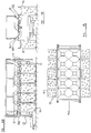
- Figure 1 is a side view of a trailer provided with a bag filling apparatus according to a first aspect of the present invention
- Figure 2 is a plan view of the trailer of Figure 1
- Figure 3 is a side view on a larger scale of part of the trailer of Figure 1,
- Figure 4 is a section on line 4-4 of Figure 3,
- Figure 5 is a partially broken away end view of the trailer of Figure 1
- Figure 6 a is a side view of the trailer of Figure 1 in a first stage of operation
- Figure 6 b is a plan view of the trailer of Figure 6 a .
- Figure 6 c is a partly broken away end view of the trailer of Figure 6 a .
- Figure 7 a is a side view of the trailer in Figure 1 in a second stage of operation
- Figure 7 b is a plan view of the trailer of Figure 7 a .
- Figure 7 c is a partly broken away end view of the trailer of Figure 7 a
- Figure 8 a is a side view of the trailer in Figure 1 in a third stage of operation
- Figure 8 b is a plan view of the trailer in Figure 8 a .
- Figure 8 c is a partly broken away end view of the trailer of Figure 8 a .
- Figure 9 a is a side view of the trailer in Figure 1 in a fourth stage of operation
- Figure 9 b is a plan view of the trailer of Figure 9 a .
- Figure 9 c is a partly broken away end view of the trailer of Figure 9 a .
- Figure 10 a is a side view of the trailer in Figure 1 in a fifth stage of operation
- Figure 10 b is a plan view of the trailer of Figure 10 a .
- Figure 10 c is a partly broken away end view of the trailer of Figure 10 a .
- Figure 11 a is a side view of the trailer in Figure 1 in a sixth stage of operation
- Figure 11 b is a plan view of the trailer of Figure 10 a .
- Figure 11 c is a partly broken away end view of the trailer of Figure 11 a .
- Figure 12 a is a plan view of the trailer of Figure 1 in a seventh stage of operation
- Figure 12 b is a plan view of the trailer of Figure 12 a .
- Figure 12 c is a partially broken away end view of the trailer of Figure 12 a .
- a vehicle V comprising a trailer 10 is shown provided with a bag filling apparatus A.
- the trailer 10 has, ground engaging means in the form of wheels 11, a pair of wheels 11 being disposed at each side of the trailer 10, a support load carrying surface 12 and a forwardly projecting tow bar 13 comprising at one end a hitch 14 for engagement with a vehicle to draw the trailer 10 and further comprising a pivotably mounted foot member 15 to maintain the load carrying surface 12 in a generally horizontal configuration when the tow bar 13 is detached from a vehicle.
- each post 16 is a vertically extending post 16 in the present example of square cross section. Telescopically received in each post 16 is an upright member 17, the pair of upright members 17 towards the front of the trailer being interconnected by a transversely extending bar 18 and the rearward pair of upright members 17 being interconnected by a transversely extending bar 19.
- the forward pair of posts 16 are each provided at their lower end with forwardly extending lower ears 20 a .
- the rearward pair of posts 16 are similarly each provided at their lower end with a pair of rearwardly extending lower ears 20 b .
- the forward pair of upright members 17 are similarly each provided with a pair of forwardly extending upper ears 21 a adjacent their upper ends whilst the rearward pair of upright members 17 are each provided with a pair of rearwardly extending upper ears 21 b .
- a lift means comprising upwardly extending fluid pressure operated ram 22.
- the four rams 22 are supplied with hydraulic fluid under pressure by a flexible hose from a suitable source e.g. from a tractor.
- the rams 22 are operable to raise and lower the corresponding upright member 17 guided by the post 16.
- the upright members 17 disposed on each side of the vehicle are interconnected by an upper longitudinal member 23 a connected adjacent to the top of each slider 17 and a lower longitudinal member 23 b connected below the upper longitudinal member.
- the upper longitudinal member 23 a and lower longitudinal member 23 b are interconnected by vertically extending struts 23 c .
- Supported on the longitudinal members 23 a , 23 b is a receptacle 24 having a pair of relatively long side walls 25 and a pair of relative short end walls 26.
- the lower part of the receptacle 24 comprises a plurality of openings 27 each comprising a lower part 27 a comprising a generally square aperture, an upper part 27 b also of generally square cross section and a plurality of inclined wall parts 27 c connecting the upper part 27 b and the lower part 27 a .
- a further downwardly extending neck part 27 d is provided attached to and extending downwardly from the lower part 27 a of each opening.
- the receptacle is provided with a plurality of such openings, in the present example ten disposed two abreast and with five of such pairs disposed along the length of the receptacle 24.
- the wall parts 27 c of adjacent openings 27 abut such that there is no part of the lower part of the receptacle 24 where produce will lodge and not enter one of the openings 27.
- a further transversely extending bar 18a is connected between the forward pair of upright members 17 generally parallel to and below the transversely extending bar 18 and at the same height as the lower longitudinal member 23 b .
- Figure 5 shows a broken away end view of the forward part of the trailer 10, it would be appreciated that equivalent structures are provided at the rearward end of the trailer 10.
- the further transversely extending bar 18 a is disposed slightly inwardly of the vehicle compared to the transversely extending bar 18.
- Connected between the transversely extending bars 18, 18 a are a pair of sleeves 28 of generally square cross-section extending generally vertically, one sleeve 28 disposed either side of the trailer in symmetrical fashion. Extending between the sleeves 28 is a connecting bar 29.
- a track means 30 comprising a pair of parallel U-shaped elements to provide an upper track 30 a and a lower track 30 b respectively (see also Fig 3).
- Connected to the track means 30 are vertically extending posts 31 slidably received in the corresponding sleeve 28.
- Auxiliary lift means comprising an auxiliary fluid operated ram 32 is provided adjacent to each sleeve 28 connected between ears 32 a provided on the connection element 29 and ears 32 b provided on the track means 30.
- the auxiliary fluid operated rams 32 are operable to raise and lower the track means 30 relative to the receptacle 24 in a direction guided by the sleeves 28 and post 31.
- a pair of longitudinally extending support bars 33 a , 33 b are disposed beneath the receptacle 24, one at each side of the trailer 10.
- a bag holding means comprising an upwardly extending generally triangular bracket 34, towards the apex of which is provided a generally horizontal tine 35 which extends in a direction generally outwardly of the apparatus.
- Two of said brackets 34 and tines 35 are provided corresponding to each opening 27, disposed below the receptacle 24 such that each tine 35 is adjacent a midpoint of the transversely extending inclined wall 27 of an opening 26.
- Bags 36 may be suspended from the tines 35, one bag for each opening 27.
- the bags 36 are suspended from the tines 35 by means of loops 37 disposed in each corner of the bags 36 through which the tines 35 pass.
- the support bars 33 a , 33 b are supported for transverse movement relative to the trailer 10 on the track means 30.
- Received in the upper track 30 a is a first carriage 38 a comprising a pair of rollers 38 b which engage the upper track 30 a .
- Support rail 33 a is attached to the carriage 38 a by bracket 38 c .
- a second carriage 39 a is provided with rollers 39 b which are received in the lower track 30 b .
- the support bar 33 b is attached to the carriage 39 a by bracket 39 c .
- the brackets 38 c , 39c are consequent of different lengths.
- the rollers 38 b , 39 b are mounted on stub shafts 40 a , 40 b respectively.
- a first transverse extension ram 41 is provided disposed parallel to and above the carriage 38 a .
- the first extension transverse ram 41 is connected between a pair of ears 42 provided on the first carriage 38 a , and a further pair of ears 43 provided on a plate 44 attached to an upper part of the track means 30.
- a second transverse extension ram 45 is similarly provided disposed parallel to and below the carriage 39 a .
- the second extension transverse ram 45 is connected between a pair of ears 46 provided on the carriage 39 a , and a further pair of ears 47 provided on a plate 48 attached to the track means 30.
- the transverse extension rams 41, 45 are operable to move the support bars 33 a , 33 b such that the tines 35 are movable between a first position wherein the tines 35 are disposed substantially underneath the receptacle 24 and a second position wherein the tines 35 extend outwardly of the receptacle 24.
- the auxiliary lift means (32 et al) is operable to lower the track means 30 relative to the receptacle as seen in Figure 4, such that the support bars 33 a , 33 b are disposed lower than the neck parts 27 d .
- the mode of operation is as follows;
- transverse extension rams 41, 45 are actuated such that the tines 35 extend outwardly of the apparatus for the greater part of their length as seen in Figures 6 b and 6 c .
- a bag 36 is suspended from each pair of tines 35 by engaging the loops 37 of the bag 36 with the tines 35.
- the auxiliary fluid operated rams 32 are operated such that the track means 30 and hence the support bars 33 a , 33 b are in a lower position relative to the receptacle 24, such that the support bars 33 a , 33 b are able to pass below the neck parts 27 d .
- the upwardly extending fluid pressure operated rams 22 are operated to position the support rails 33 a , 33 b at a height such that when the bags are mounted on the tines 35, the base of each bag 36 rests on the ground.
- each pair of tines 35 in a second stage of operation the upwardly extending fluid pressure operated rams 22 are operated to raise receptacle 24 and hence the track means 30 and the support bars 33 a , 33b such that the bottom part of each bag 38 is higher than the load carrying surface 12, as seen in Figures 7 a and 7 b .
- the transversely extension rams 41, 45 are then operated to retract the tines 35 in a direction inwardly of the apparatus.
- the tines 35 are shown in partly retracted position part way between the first position and the second position, with the support bars 33 a , 33 b passing below the neck parts 27 d .
- the tines 35 are shown in their retracted position in Figures 8 a , 8 b , 8 c .
- the auxiliary fluid operated rams 32 are further operated to raise the track means 30 relative to the receptacle 24, such that the support bars 33 a , 33 b are raised above the bottom of the neck part 27 d , such that each neck part 27 d is at partly received in the corresponding bag 36.
- produce 50 is introduced into the receptacle 24, for example by means of a conveyor 51 from a suitable harvesting device (not shown).
- the upwardly extending fluid pressure operated rams 22 are operated to raise the receptacle 24.
- the support bars 33 a , 33 b and receptacle 24 are raised, the upper part of the bags 36 are lifted and produce 50 descends from the receptacle 24 through the openings 27 into the bags 36.
- the lower part of each bag 36 is supported on the load carrying surface 12.
- the upwardly extending fluid pressure operated rams 22 continue to lift the support bars 33 a , 33 b and receptacle 24 until the lower part of each bag 38 is suspended spaced from the load carrying surface 12 and the produce has been transferred from the receptacle into the bags 36, as shown in Figures 10 a to 10 c .
- the auxiliary fluid operated rams 32 ensure that produce 50 is received within the bags 36 by raising the mouth of each bag 36 above the bottom of the neck parts 27 d .
- the use of the apparatus according to the invention thus reduces damage to the produce since the produce is loaded into the bags 36 by raising the receptacle 24, rather than, for example, being dropped onto other produce in a bag or box.
- the provision of the apparatus on a trailer or other vehicle is particularly advantageous.
- the receptacle 24 may be filled directly from the harvesting apparatus, and the filled bags 36 carried to the edge of the field or to another convenient pick up point for loading directly onto lorries for transport to a processing plant or other site. The need to transport the produce in a trailer to a central loading point for loading into containers for onward transport is entirely removed.
- the apparatus is mounted on a trailer or other vehicle
- the apparatus itself can be used to transport the filled bags 36 to the field edge or other pick up point, or alternatively, filled bags can be left in the field for subsequent collection.
- the simultaneous loading of a plurality, in the present example ten, 1.2 tonne bags add greatly to the speed and efficiency of the filling operation as does the relative ease of unloading filled bags 36 from the apparatus and supplying empty bags 36. Since the bags 36 are considerably lighter than conventional one tonne boxes, the cost and other problems associated with the return of the boxes to the farm is much reduced.
- an apparatus A according to the present invention is shown provided on a vehicle comprising a trailer 10, it will be apparent that an apparatus A could be mounted as a static loading apparatus to take advantage of the reduced level of damage to produce during loading at a central loading point.
- the apparatus A is mounted on a trailer 10 and is supplied with hydraulic fluid under pressure from a separate source, for example a tractor, the apparatus may be provided with its own source of fluid pressure, and indeed be provided on a vehicle with its own motor which may also provide motive power to the vehicle.
- a separate source for example a tractor
- the apparatus may be provided with its own source of fluid pressure, and indeed be provided on a vehicle with its own motor which may also provide motive power to the vehicle.
- other means could be provided in place of the fluid pressure operated rams 22, 32, 41, 45, for example electrical or mechanical drives as appropriate.
Landscapes
- Engineering & Computer Science (AREA)
- Mechanical Engineering (AREA)
- Life Sciences & Earth Sciences (AREA)
- Agronomy & Crop Science (AREA)
- Supplying Of Containers To The Packaging Station (AREA)
Abstract
Description
- This invention relates to a bag filling apparatus preferably but not exclusively for filling bags with produce.
- Produce, such as potatoes, is commonly stored and transported in wooden one tonne boxes. These boxes are usually filled at a central location with produce being carried to said central location by trailer or bulk transport from the fields from which the produce is being harvested. After being filled, the boxes are loaded on an appropriate vehicle for transport of the produce to its destination, for example a processing plant. When the boxes have been emptied of produce at their destination, the boxes have to returned to the central location for reuse. This method of handling produce causes unnecessary damage to the produce which can reduce the value of the produce, and requires that the empty boxes be returned to the central location, thus incurring additional transport costs.
- As a result, bags are becoming more popular than boxes, but again produce must still be transported to a central location where the bags are filled, and damage to the produce can still result during filling of the bags.
- An aim of the invention is to provide a new or improved bag filling apparatus.
- According to a first aspect of the present invention we provide a bag filling apparatus comprising a receptacle for produce, the receptacle having an opening, a bag holding means disposed to hold a bag below said opening, and a support means adapted to engage said bag wherein said support means and said bag holding means are relatively movable.
- Lifting means may be provided to move the bag holding means relative to the support means.
- Said lifting means may be operable to move said receptacle relative to said support means and said bag holding means may be movable with said receptacle.
- Said lift means may comprise a fluid pressure operated ram.
- The bag holding means may comprise a plurality of tines.
- Said tines may engage suspension means provided on said bag.
- The bag holding means may be movable by transverse movement means between a first position to permit a bag held in said bag holding means to be filled and a second position to permit a bag to engage or disengage from said bag holding means.
- When in the first position, said bag holding means may be substantially below said receptacle.
- When in the second position, said bag holding means may be disposed away from said opening.
- Said transverse movement means may comprise a fluid pressure operated ram.
- The support means may comprise a generally horizontal platform disposed below said receptacle.
- The apparatus may comprise a plurality of bag holding means and wherein the receptacle may comprise a plurality of corresponding openings.
- Each opening may comprise a lower part having a first width, an upper part having a second width greater than said first width, and an inclined wall connecting said lower part and said upper part.
- Said bag holding means may be disposed between said wall parts of adjacent openings.
- At least some of said bag holding means may be provided on a common support, said common support being movable by said transverse movement means to move said at least some of said bag holding means between said first position and said second position.
- The apparatus may comprise auxiliary lift means to move the bag holding means relative to the receptacle.
- Said bags may comprise 1.2 tonne bags.
- According to a second aspect of the invention we provide a vehicle carrying a bag filling apparatus according to the first aspect of the invention.
- The vehicle may comprise a trailer having a chassis, ground engaging means and a hitch means to enable the trailer to be drawn by another vehicle.
- Said support means may comprise a load carrying part of said vehicle.
- According to a third aspect of the invention we provide a method of filling a bag by means of an apparatus according to the first aspect of the invention or a vehicle according to the second aspect of the invention comprising the steps of providing said bag holder with a bag, operating said lift means such that said support means holds a lower part of said bag adjacent said opening, disposing produce in said receptacle and operating said lift means to raise said receptacle relative to said support part such that produce passes from said receptacle through said opening into said bag.
- The method may further comprise the step of extending said bag holding means transversely of said apparatus to permit said bag to be removed from said apparatus.
- The invention will now be described by way of example only, with reference to the accompanying drawings wherein
- Figure 1 is a side view of a trailer provided with a bag filling apparatus according to a first aspect of the present invention,
- Figure 2 is a plan view of the trailer of Figure 1,
- Figure 3 is a side view on a larger scale of part of the trailer of Figure 1,
- Figure 4 is a section on line 4-4 of Figure 3,
- Figure 5 is a partially broken away end view of the trailer of Figure 1,
- Figure 6a is a side view of the trailer of Figure 1 in a first stage of operation,
- Figure 6b is a plan view of the trailer of Figure 6a,
- Figure 6c is a partly broken away end view of the trailer of Figure 6a,
- Figure 7a is a side view of the trailer in Figure 1 in a second stage of operation,
- Figure 7b is a plan view of the trailer of Figure 7a, and
- Figure 7c is a partly broken away end view of the trailer of Figure 7a
- Figure 8a is a side view of the trailer in Figure 1 in a third stage of operation,
- Figure 8b is a plan view of the trailer in Figure 8a, and
- Figure 8c is a partly broken away end view of the trailer of Figure 8a,
- Figure 9a is a side view of the trailer in Figure 1 in a fourth stage of operation,
- Figure 9b is a plan view of the trailer of Figure 9a, and
- Figure 9c is a partly broken away end view of the trailer of Figure 9a,
- Figure 10a is a side view of the trailer in Figure 1 in a fifth stage of operation,
- Figure 10b is a plan view of the trailer of Figure 10a, and
- Figure 10c is a partly broken away end view of the trailer of Figure 10a,
- Figure 11a is a side view of the trailer in Figure 1 in a sixth stage of operation,
- Figure 11b is a plan view of the trailer of Figure 10a, and
- Figure 11c is a partly broken away end view of the trailer of Figure 11a,
- Figure 12a is a plan view of the trailer of Figure 1 in a seventh stage of operation,
- Figure 12b is a plan view of the trailer of Figure 12a, and
- Figure 12c is a partially broken away end view of the trailer of Figure 12a.
- Referring now to Figures 1 to 4, a vehicle V comprising a
trailer 10 is shown provided with a bag filling apparatus A. Thetrailer 10 has, ground engaging means in the form ofwheels 11, a pair ofwheels 11 being disposed at each side of thetrailer 10, a supportload carrying surface 12 and a forwardly projectingtow bar 13 comprising at one end ahitch 14 for engagement with a vehicle to draw thetrailer 10 and further comprising a pivotably mountedfoot member 15 to maintain theload carrying surface 12 in a generally horizontal configuration when thetow bar 13 is detached from a vehicle. - Provided at each corner of the
trailer 10 is a vertically extendingpost 16 in the present example of square cross section. Telescopically received in eachpost 16 is anupright member 17, the pair ofupright members 17 towards the front of the trailer being interconnected by a transversely extendingbar 18 and the rearward pair ofupright members 17 being interconnected by a transversely extendingbar 19. - The forward pair of
posts 16 are each provided at their lower end with forwardly extendinglower ears 20a. The rearward pair ofposts 16 are similarly each provided at their lower end with a pair of rearwardly extendinglower ears 20b. The forward pair ofupright members 17 are similarly each provided with a pair of forwardly extendingupper ears 21a adjacent their upper ends whilst the rearward pair ofupright members 17 are each provided with a pair of rearwardly extendingupper ears 21b. Connected between thelower ears upper ears post 16 andupright member 17 is a lift means comprising upwardly extending fluid pressure operatedram 22. In operation, the fourrams 22 are supplied with hydraulic fluid under pressure by a flexible hose from a suitable source e.g. from a tractor. Therams 22 are operable to raise and lower thecorresponding upright member 17 guided by thepost 16. - The
upright members 17 disposed on each side of the vehicle are interconnected by an upper longitudinal member 23a connected adjacent to the top of eachslider 17 and a lower longitudinal member 23b connected below the upper longitudinal member. The upper longitudinal member 23a and lower longitudinal member 23b are interconnected by vertically extending struts 23c. Supported on the longitudinal members 23a, 23b is areceptacle 24 having a pair of relativelylong side walls 25 and a pair of relativeshort end walls 26. The lower part of thereceptacle 24 comprises a plurality ofopenings 27 each comprising alower part 27a comprising a generally square aperture, anupper part 27b also of generally square cross section and a plurality of inclined wall parts 27c connecting theupper part 27b and thelower part 27a. A further downwardly extendingneck part 27d is provided attached to and extending downwardly from thelower part 27a of each opening. The receptacle is provided with a plurality of such openings, in the present example ten disposed two abreast and with five of such pairs disposed along the length of thereceptacle 24. The wall parts 27c ofadjacent openings 27 abut such that there is no part of the lower part of thereceptacle 24 where produce will lodge and not enter one of theopenings 27. - Referring now to Figure 5, a further transversely extending bar 18a is connected between the forward pair of
upright members 17 generally parallel to and below the transversely extendingbar 18 and at the same height as the lower longitudinal member 23b. Although Figure 5 shows a broken away end view of the forward part of thetrailer 10, it would be appreciated that equivalent structures are provided at the rearward end of thetrailer 10. The further transversely extending bar 18a is disposed slightly inwardly of the vehicle compared to the transversely extendingbar 18. Connected between the transversely extendingbars 18, 18a are a pair ofsleeves 28 of generally square cross-section extending generally vertically, onesleeve 28 disposed either side of the trailer in symmetrical fashion. Extending between thesleeves 28 is a connectingbar 29. Provided at each end of the trailer disposed generally transversely horizontally is a track means 30 comprising a pair of parallel U-shaped elements to provide anupper track 30a and alower track 30b respectively (see also Fig 3). Connected to the track means 30 are vertically extendingposts 31 slidably received in thecorresponding sleeve 28. Auxiliary lift means comprising an auxiliary fluid operatedram 32 is provided adjacent to eachsleeve 28 connected between ears 32a provided on theconnection element 29 andears 32b provided on the track means 30. The auxiliary fluid operatedrams 32 are operable to raise and lower the track means 30 relative to thereceptacle 24 in a direction guided by thesleeves 28 andpost 31. - Referring to Figures 3 and 4, a pair of longitudinally extending
support bars receptacle 24, one at each side of thetrailer 10. Provided on eachsupport bar triangular bracket 34, towards the apex of which is provided a generallyhorizontal tine 35 which extends in a direction generally outwardly of the apparatus. Two of saidbrackets 34 andtines 35 are provided corresponding to eachopening 27, disposed below thereceptacle 24 such that eachtine 35 is adjacent a midpoint of the transversely extendinginclined wall 27 of anopening 26.Bags 36 may be suspended from thetines 35, one bag for eachopening 27. Thebags 36 are suspended from thetines 35 by means ofloops 37 disposed in each corner of thebags 36 through which thetines 35 pass. - The support bars 33a, 33b are supported for transverse movement relative to the
trailer 10 on the track means 30. Received in theupper track 30a is a first carriage 38a comprising a pair ofrollers 38b which engage theupper track 30a.Support rail 33a is attached to the carriage 38a by bracket 38c. Similarly, asecond carriage 39a is provided withrollers 39b which are received in thelower track 30b. Thesupport bar 33b is attached to thecarriage 39a by bracket 39c. Because the support bars 33a, 33b are at the same height while thecarriages rollers stub shafts 40a, 40b respectively. - A first
transverse extension ram 41 is provided disposed parallel to and above the carriage 38a. The first extensiontransverse ram 41 is connected between a pair ofears 42 provided on the first carriage 38a, and a further pair ofears 43 provided on aplate 44 attached to an upper part of the track means 30. A secondtransverse extension ram 45 is similarly provided disposed parallel to and below thecarriage 39a. The second extensiontransverse ram 45 is connected between a pair ofears 46 provided on thecarriage 39a, and a further pair ofears 47 provided on aplate 48 attached to the track means 30. - The transverse extension rams 41, 45 are operable to move the support bars 33a, 33b such that the
tines 35 are movable between a first position wherein thetines 35 are disposed substantially underneath thereceptacle 24 and a second position wherein thetines 35 extend outwardly of thereceptacle 24. The auxiliary lift means (32 et al) is operable to lower the track means 30 relative to the receptacle as seen in Figure 4, such that the support bars 33a, 33b are disposed lower than theneck parts 27d. In Figure 4, once the auxiliary lift means (32 et al) have been operated to lower the track means 30, operation of firsttransverse extension ram 41 will cause the carriage 38a and hence thesupport bar 33a to move to the left as seen in Figure 4, extending the tines on the left hand side of the receptacle. - The mode of operation is as follows;
- Referring to Figures 6a to 6c, in a first stage of operation the transverse extension rams 41, 45 are actuated such that the
tines 35 extend outwardly of the apparatus for the greater part of their length as seen in Figures 6b and 6c. Abag 36 is suspended from each pair oftines 35 by engaging theloops 37 of thebag 36 with thetines 35. - The auxiliary fluid operated
rams 32 are operated such that the track means 30 and hence the support bars 33a, 33b are in a lower position relative to thereceptacle 24, such that the support bars 33a, 33b are able to pass below theneck parts 27d. The upwardly extending fluid pressure operatedrams 22 are operated to position the support rails 33a, 33b at a height such that when the bags are mounted on thetines 35, the base of eachbag 36 rests on the ground. Once abag 36 is provided on each pair oftines 35, in a second stage of operation the upwardly extending fluid pressure operatedrams 22 are operated to raisereceptacle 24 and hence the track means 30 and the support bars 33a, 33b such that the bottom part of eachbag 38 is higher than theload carrying surface 12, as seen in Figures 7a and 7b. The transversely extension rams 41, 45 are then operated to retract thetines 35 in a direction inwardly of the apparatus. In Figures 7b and 7c thetines 35 are shown in partly retracted position part way between the first position and the second position, with the support bars 33a, 33b passing below theneck parts 27d. Thetines 35 are shown in their retracted position in Figures 8a, 8b, 8c. - In a fourth stage of operation as shown in Figures 9a to 9c, once the
tines 35 have been retracted such that eachbag 36 is disposed beneath thecorresponding opening 27, the upwardly extending fluid pressure operatedrams 22 are operated to lower the support bars 33a, 33b andreceptacle 24 such that a lower part of thebags 36 engages theload carrying surface 12. As thebar bags 36 collapse in a concertina fashion as shown in Figure 9a. The auxiliary fluid operatedrams 32 are further operated to raise the track means 30 relative to thereceptacle 24, such that the support bars 33a, 33b are raised above the bottom of theneck part 27d, such that eachneck part 27d is at partly received in the correspondingbag 36. In this position, produce 50 is introduced into thereceptacle 24, for example by means of aconveyor 51 from a suitable harvesting device (not shown). - To fill the
bags 36 with theproduce 50 once thereceptacle 24 has been provided with a sufficient quantity of produce, in a fifth stage of operation the upwardly extending fluid pressure operatedrams 22 are operated to raise thereceptacle 24. As the support bars 33a, 33b andreceptacle 24 are raised, the upper part of thebags 36 are lifted and produce 50 descends from thereceptacle 24 through theopenings 27 into thebags 36. During at least-part of the lifting process, the lower part of eachbag 36 is supported on theload carrying surface 12. The upwardly extending fluid pressure operatedrams 22 continue to lift the support bars 33a, 33b andreceptacle 24 until the lower part of eachbag 38 is suspended spaced from theload carrying surface 12 and the produce has been transferred from the receptacle into thebags 36, as shown in Figures 10a to 10c. The auxiliary fluid operatedrams 32 ensure thatproduce 50 is received within thebags 36 by raising the mouth of eachbag 36 above the bottom of theneck parts 27d. - In a sixth stage of operation as shown in Figures 11a to 11c, to unload the
full bags 36 thetines 35 are first lowered by operation of the auxiliary fluid operatedrams 32 until the support bars 33a, 33b are below theneck parts 27d. Thetines 35 are then moved to their second position by operation of the transverse extension rams 41, 45 such that thetines 35 extend outwardly of thevehicle 10 and such that thebags 36 are suspended clear of theload carrying surface 12. The upwardly extending fluid pressure operatedrams 22 are then operated to lower the support bars 33a, 33b andreceptacle 24 such that thebags 36 rest on the ground as shown in Figures 11a and 11c. As shown in Figures 12a to 12c, in a seventh stage of operation thetines 35 are then retracted out of engagement with theloops 37 of thebags 36 and moved to their first position by the transverse fluid pressure operated rams 41, 45. Thebags 36 may then be removed, for example by means of a forklift truck or other suitable material handling vehicle, or indeed theapparatus 10 may be towed to a new position. To load additional produce, new bags are provided as shown in Figures 6a to 6c and the operation is repeated. - The use of the apparatus according to the invention thus reduces damage to the produce since the produce is loaded into the
bags 36 by raising thereceptacle 24, rather than, for example, being dropped onto other produce in a bag or box. The provision of the apparatus on a trailer or other vehicle is particularly advantageous. Thereceptacle 24 may be filled directly from the harvesting apparatus, and the filledbags 36 carried to the edge of the field or to another convenient pick up point for loading directly onto lorries for transport to a processing plant or other site. The need to transport the produce in a trailer to a central loading point for loading into containers for onward transport is entirely removed. Where the apparatus is mounted on a trailer or other vehicle, the apparatus itself can be used to transport the filledbags 36 to the field edge or other pick up point, or alternatively, filled bags can be left in the field for subsequent collection. The simultaneous loading of a plurality, in the present example ten, 1.2 tonne bags add greatly to the speed and efficiency of the filling operation as does the relative ease of unloading filledbags 36 from the apparatus and supplyingempty bags 36. Since thebags 36 are considerably lighter than conventional one tonne boxes, the cost and other problems associated with the return of the boxes to the farm is much reduced. - Although in the present example an apparatus A according to the present invention is shown provided on a vehicle comprising a
trailer 10, it will be apparent that an apparatus A could be mounted as a static loading apparatus to take advantage of the reduced level of damage to produce during loading at a central loading point. - Although in the present example, the apparatus A is mounted on a
trailer 10 and is supplied with hydraulic fluid under pressure from a separate source, for example a tractor, the apparatus may be provided with its own source of fluid pressure, and indeed be provided on a vehicle with its own motor which may also provide motive power to the vehicle. Alternatively, other means could be provided in place of the fluid pressure operated rams 22, 32, 41, 45, for example electrical or mechanical drives as appropriate. - In the present specification "comprise" means "includes or consists of and "comprising" means "including or consisting of'.
- The features disclosed in the foregoing description, or the following claims, or the accompanying drawings, expressed in their specific forms or in terms of a means for performing the disclosed function, or a method or process for attaining the disclosed result, as appropriate, may, separately, or in any combination of such features, be utilised for realising the invention in diverse forms thereof.
Claims (21)
- A bag filling apparatus comprising a receptacle for produce, the receptacle having an opening, a bag holding means disposed to hold a bag below said opening, and a support means adapted to engage said bag wherein said support means and said bag holding means are relatively movable.
- An apparatus according to Claim wherein lifting means is provided to move the bag holding means relative to the support means.
- An apparatus according to Claim 2 wherein said lifting means is operable to move said receptacle relative to said support means and said bag holding means is movable with said receptacle.
- An apparatus according to Claim 2 or Claim 3 wherein said lift means comprises a fluid pressure operated ram.
- An apparatus according to any one of the preceding claims wherein the bag holding means comprises a plurality of tines.
- An apparatus according to Claim 5 wherein said tines are adapted to engage suspension means provided on said bag.
- An apparatus according to any one of the preceding claims wherein the bag holding means is movable by transverse movement means between a first to permit a bag held on said bag holding means to be filled and a second position to permit a bag to be engaged or disengaged from said bag holding means.
- An apparatus according to Claim 7 wherein when said bag holding means is in the first position, the bag holding means is substantially below said receptacle.
- An apparatus according to Claim 7 or Claim 8 wherein when the bag holding means is in the second position, said bag holding means is disposed away from said opening.
- An apparatus according to any one of Claims 7 to 9 wherein said transverse movement means comprises a fluid pressure operated ram.
- An apparatus according to any one of the preceding claims wherein the support means comprises a generally horizontal platform disposed below said receptacle.
- An apparatus according to any one of the preceding claims wherein the apparatus comprises a plurality of bag holding means and wherein the receptacle comprises a plurality of corresponding openings.
- An apparatus according to Claim 12 wherein each opening comprises a lower part having a first cross-sectional area, an upper part having a second cross-sectional area greater than said first width, and an inclined wall connecting said lower part and said upper part.
- An apparatus according to Claim 13 wherein said bag holding means is disposed between said wall parts of adjacent openings.
- An apparatus according to any one of Claims 12 to 14 where dependent directly or indirectly on Claim 7 wherein at least some of said bag holding means are provided on a common support, said common support being movable by said transverse movement means to move said at least some of said bag holding means between said first position and said second position.
- An apparatus according to any one of the preceding claims comprising auxiliary lift means to move the bag holding means relative to the receptacle.
- A vehicle comprising a bag filling apparatus according to any one of Claims 1 to 16.
- A vehicle according to Claim 17 wherein the vehicle comprises a trailer having a chassis, ground engaging means and a hitch means to enable the trailer to be drawn by another vehicle.
- A vehicle according to Claim 17 or 18 wherein said support means comprises a load carrying part of said vehicle.
- A method of filling a bag by means of an apparatus according to any one of Claims 1 to 16 or a vehicle according to any one of Claims 17 to 19 comprising the steps of providing said bag holder with a bag, operating said lift means such that said support means holds a lower part of said bag adjacent said opening, disposing produce in said receptacle and operating said lift means to raise said receptacle relative to said support means such that produce passes from said receptacle through said opening into said bag.
- A method according to Claim 20 further comprising the step of extending said bag holding means transversely of said apparatus to permit said bag to be removed from said apparatus.
Applications Claiming Priority (2)
| Application Number | Priority Date | Filing Date | Title |
|---|---|---|---|
| GB0014236 | 2000-06-13 | ||
| GB0014236A GB2364289B (en) | 2000-06-13 | 2000-06-13 | Bag filling apparatus |
Publications (1)
| Publication Number | Publication Date |
|---|---|
| EP1167207A1 true EP1167207A1 (en) | 2002-01-02 |
Family
ID=9893423
Family Applications (1)
| Application Number | Title | Priority Date | Filing Date |
|---|---|---|---|
| EP01114237A Withdrawn EP1167207A1 (en) | 2000-06-13 | 2001-06-12 | Bag filling apparatus |
Country Status (2)
| Country | Link |
|---|---|
| EP (1) | EP1167207A1 (en) |
| GB (1) | GB2364289B (en) |
Cited By (3)
| Publication number | Priority date | Publication date | Assignee | Title |
|---|---|---|---|---|
| NL1026298C2 (en) * | 2003-11-06 | 2005-05-09 | Leon Augustinus Gabriel V Meir | Device and method for filling a container for storage and / or transport with product. |
| CN108860788A (en) * | 2018-07-17 | 2018-11-23 | 山东阿林达科技发展有限公司 | High mixer erucyl amide particle material-receiving device and its working method |
| CN112455814A (en) * | 2020-11-26 | 2021-03-09 | 马鞍山学院 | Detection device and detection method for automatic bagging weighing |
Citations (5)
| Publication number | Priority date | Publication date | Assignee | Title |
|---|---|---|---|---|
| GB645399A (en) * | 1948-09-21 | 1950-11-01 | Ronald Leslie Flux | Improvements in or relating to devices for supporting sacks to be loaded |
| US2643804A (en) * | 1948-11-02 | 1953-06-30 | Staley Mfg Co A E | Bag filling tube and associated bag top gripping apparatus |
| US3830266A (en) * | 1973-03-23 | 1974-08-20 | Okinkraft Inc | Drop-down fill spout for bag filling machine |
| GB1426994A (en) * | 1973-03-09 | 1976-03-03 | Librawerk Pelz & Nagel Kg | Bagging device |
| FR2748453A1 (en) * | 1996-05-09 | 1997-11-14 | Rabaud Francois | Hold open frame for loading waste bags |
Family Cites Families (3)
| Publication number | Priority date | Publication date | Assignee | Title |
|---|---|---|---|---|
| DE2824949A1 (en) * | 1978-06-07 | 1979-12-20 | Hansaliv Gurte Gmbh & Co Kg | DEVICE FOR FILLING FLEXIBLE CONTAINERS |
| SE7810684L (en) * | 1978-10-13 | 1980-04-14 | Carlsson Sune Justus Roland | DEVICE FOR FILLING ONE OR MULTI-WALL PACKAGING |
| US5054274A (en) * | 1990-09-10 | 1991-10-08 | Sokichi Tanaka | Automatic molten substance bagging method and system |
-
2000
- 2000-06-13 GB GB0014236A patent/GB2364289B/en not_active Expired - Lifetime
-
2001
- 2001-06-12 EP EP01114237A patent/EP1167207A1/en not_active Withdrawn
Patent Citations (5)
| Publication number | Priority date | Publication date | Assignee | Title |
|---|---|---|---|---|
| GB645399A (en) * | 1948-09-21 | 1950-11-01 | Ronald Leslie Flux | Improvements in or relating to devices for supporting sacks to be loaded |
| US2643804A (en) * | 1948-11-02 | 1953-06-30 | Staley Mfg Co A E | Bag filling tube and associated bag top gripping apparatus |
| GB1426994A (en) * | 1973-03-09 | 1976-03-03 | Librawerk Pelz & Nagel Kg | Bagging device |
| US3830266A (en) * | 1973-03-23 | 1974-08-20 | Okinkraft Inc | Drop-down fill spout for bag filling machine |
| FR2748453A1 (en) * | 1996-05-09 | 1997-11-14 | Rabaud Francois | Hold open frame for loading waste bags |
Cited By (4)
| Publication number | Priority date | Publication date | Assignee | Title |
|---|---|---|---|---|
| NL1026298C2 (en) * | 2003-11-06 | 2005-05-09 | Leon Augustinus Gabriel V Meir | Device and method for filling a container for storage and / or transport with product. |
| EP1529727A1 (en) * | 2003-11-06 | 2005-05-11 | van Meir, Leon Augustinus Gabriel | Device and method of filling a container with product for storage and/or transport thereof |
| CN108860788A (en) * | 2018-07-17 | 2018-11-23 | 山东阿林达科技发展有限公司 | High mixer erucyl amide particle material-receiving device and its working method |
| CN112455814A (en) * | 2020-11-26 | 2021-03-09 | 马鞍山学院 | Detection device and detection method for automatic bagging weighing |
Also Published As
| Publication number | Publication date |
|---|---|
| GB2364289A (en) | 2002-01-23 |
| GB0014236D0 (en) | 2000-08-02 |
| GB2364289B (en) | 2004-03-03 |
Similar Documents
| Publication | Publication Date | Title |
|---|---|---|
| US8573917B2 (en) | Bulk seed handling system | |
| US5476356A (en) | Bale handling apparatus | |
| US5520495A (en) | Method and means for filling field planters from bulk seed containers | |
| US5807053A (en) | Multiple hay bale transporter and loader | |
| US4519189A (en) | Telescoping basket cover | |
| US4104850A (en) | Method of harvesting and transporting grain | |
| HU213891B (en) | Device for collecting refuse, mainly domestic refuse | |
| US4537548A (en) | Combination hay hauler and stock trailer | |
| US11491904B1 (en) | Material collection and transfer cart | |
| US4521149A (en) | Bale handling machine | |
| US4144655A (en) | Portable storage bin | |
| CN211712549U (en) | Hydraulic forklift | |
| GB2026429A (en) | Load lifting and transporting vehicle | |
| GB2364289A (en) | Bag Filling Apparatus | |
| GB2153339A (en) | Fork lift agricultural trailer | |
| US2244857A (en) | Bucker, stacker, and loader | |
| US20090107775A1 (en) | Sod Harvester | |
| US6315514B1 (en) | Adjustable bow lift apparatus for a module truck | |
| US3690691A (en) | Method and apparatus for harvesting baled crops | |
| CN220998445U (en) | Material taking and loading machine | |
| IES20110024A2 (en) | Machinery for handling heavy loads | |
| KR101709777B1 (en) | Slide deck structure provided in a vehicle charger | |
| CN220200769U (en) | Auxiliary frame of feed ton packaging vehicle | |
| GB2395935A (en) | Apparatus for lifting and handling bales | |
| US3799378A (en) | Method for harvesting baled crops |
Legal Events
| Date | Code | Title | Description |
|---|---|---|---|
| PUAI | Public reference made under article 153(3) epc to a published international application that has entered the european phase |
Free format text: ORIGINAL CODE: 0009012 |
|
| AK | Designated contracting states |
Kind code of ref document: A1 Designated state(s): AT BE CH CY DE DK ES FI FR GB GR IE IT LI LU MC NL PT SE TR |
|
| AX | Request for extension of the european patent |
Free format text: AL;LT;LV;MK;RO;SI |
|
| 17P | Request for examination filed |
Effective date: 20020626 |
|
| AKX | Designation fees paid |
Free format text: AT BE CH CY DE DK ES FI FR GB GR IE IT LI LU MC NL PT SE TR |
|
| 17Q | First examination report despatched |
Effective date: 20031217 |
|
| GRAP | Despatch of communication of intention to grant a patent |
Free format text: ORIGINAL CODE: EPIDOSNIGR1 |
|
| STAA | Information on the status of an ep patent application or granted ep patent |
Free format text: STATUS: THE APPLICATION IS DEEMED TO BE WITHDRAWN |
|
| 18D | Application deemed to be withdrawn |
Effective date: 20060307 |