EP1167027A2 - Cylinder Apparatus for rotary printing press - Google Patents
Cylinder Apparatus for rotary printing press Download PDFInfo
- Publication number
- EP1167027A2 EP1167027A2 EP01114483A EP01114483A EP1167027A2 EP 1167027 A2 EP1167027 A2 EP 1167027A2 EP 01114483 A EP01114483 A EP 01114483A EP 01114483 A EP01114483 A EP 01114483A EP 1167027 A2 EP1167027 A2 EP 1167027A2
- Authority
- EP
- European Patent Office
- Prior art keywords
- cylinder
- eccentric
- abutting
- cylinders
- pair
- Prior art date
- Legal status (The legal status is an assumption and is not a legal conclusion. Google has not performed a legal analysis and makes no representation as to the accuracy of the status listed.)
- Granted
Links
Images



Classifications
-
- B—PERFORMING OPERATIONS; TRANSPORTING
- B41—PRINTING; LINING MACHINES; TYPEWRITERS; STAMPS
- B41F—PRINTING MACHINES OR PRESSES
- B41F13/00—Common details of rotary presses or machines
- B41F13/08—Cylinders
- B41F13/24—Cylinder-tripping devices; Cylinder-impression adjustments
- B41F13/26—Arrangement of cylinder bearings
- B41F13/28—Bearings mounted eccentrically of the cylinder axis
Definitions
- the present invention relates to a cylinder apparatus for a rotary printing press which adjusts throw-on and throw-off of cylinders in contact opposite to each other, and the skew of a cylinder.
- a cylinder apparatus for a rotary printing press of this type has a plate registration unit for adjusting register of plates.
- U.S.P. No. 5,311,817 discloses a cylinder apparatus for a rotary printing press of this type. In the cylinder apparatus disclosed in reference 1, one end shaft of a plate cylinder is supported by one frame through an eccentric outer bearing, and the other end shaft thereof is supported by the other frame through eccentric inner and outer bearings.
- a gap where lubricating oil is to be supplied is formed between the inner and outer bearings and between the outer bearing and the frame to correspond to the amount of eccentricity, so that the eccentric inner and outer bearings are pivoted smoothly.
- This gap is generally called a clearance.
- the plate cylinder has a notch on its outer surface for winding the plate, and the blanket cylinder has a notch for winding a blanket.
- a cylinder apparatus for a rotary printing press comprising a pair of first eccentric bearings for rotatatively supporting two ends of at least one first cylinder, the first eccentric bearings having abutting portions, a second eccentric bearing for pivotally supporting one of the first eccentric bearings, a pair of support members arranged to oppose each other through a predetermined distance and adapted to pivotally support the second eccentric bearing and the other one of the first eccentric bearings, a pair of first driving means for pivoting the first eccentric bearings supported by one of the support members and the second eccentric bearing, second driving means for pivoting the second eccentric bearing supported by the other one of the support members, and a pair of abutting members which are supported by the support members and against which the abutting portions of the first eccentric bearings abut when the first cylinder abuts against a second cylinder upon driving operation of the first driving means.
- Fig. 1 shows a cylinder apparatus for a rotary printing press according to the first embodiment of the present invention.
- a pair of frames 1A and 1B oppose each other through a predetermined gap.
- An outer bearing 3 serving as the second eccentric bearing is pivotally mounted in a bearing hole 2A formed in the frame 1A
- an inner bearing 4 serving as the first eccentric bearing is pivotally mounted on the outer bearing 3.
- clearances 31 and 41 are set between the bearing hole 2A and the outer surface of the outer bearing 3 and between the inner surface of the outer bearing 3 and the outer surface of the inner bearing 4, respectively, and lubricating oil is to be supplied there, so that the outer and inner bearings 3 and 4 can pivot smoothly.
- an engaging projection 4b with a radially flat engaging surface 4c to abut against an abutting member 30a projects from the peripheral edge of a flange 4a in contact opposite to the inner surface of the frame 1A of the inner bearing 4.
- a forming direction A in which the engaging surface 4c of the engaging projection 4b is formed substantially coincides with the skew direction 40 of the plate cylinder 7 in which the plate cylinder 7 moves when the outer bearing 3 is pivoted.
- the frame 1B has a bearing hole 2B.
- An inner bearing 6 serving as the first eccentric bearing is pivotally mounted in the bearing hole 2B, and a clearance 61 is set between the outer surface of the inner bearing 6 and the bearing hole 2B.
- An engaging projection 6b with a radially flat engaging surface 6c to abut against another abutting member 30a projects from a flange 6a in contact opposite to the inner surface of the frame 1B of the inner bearing 6.
- the plate cylinder 7 is arranged in contact opposite to a blanket cylinder 8, and end shafts 7A and 7B of the plate cylinder 7 are rotatatively axially supported by the inner bearings 4 and 6 through bearings 9.
- Axes C1 of the inner bearings 4 and 6 are eccentric from an axis C of the plate cylinder 7 by t1, and an axis C2 of the outer bearing 3 is eccentric from the axis C1 of the inner bearing 4 by t2.
- a pair of cylinders 11A and 11B are pivotally mounted on the inner surfaces of the frames 1A and 1B so as to oppose each other.
- Rods 12A and 12B of the cylinders 11A and 11B are pivotally mounted on pivotal mount portions 13A and 13B of those flanges 4a and 6a of the inner bearings 4 and 6 which are in contact with the inner surfaces of the frames 1A and 1B.
- the pivotal mount portions 13A and 13B and the engaging projections 4b and 6b of the inner bearings 4 and 6 are positioned such that they are phase-shifted from each other by substantially 180° through the axis C of the plate cylinder 7.
- the forward/backward moving directions of the rods 12A and 12B of the cylinders 11A and 11B are set substantially parallel to a line B that connects the axis C of the plate cylinder 7 and an axis C3 of the blanket cylinder 8.
- a line B that connects the axis C of the plate cylinder 7 and an axis C3 of the blanket cylinder 8.
- the inner bearings 4 and 6 and the outer bearing 3 are not shown.
- part of the outer surface of the inner bearing 6 serves as an urging portion 44 to urge part of the inner surface of the bearing hole 2A of the frame 1A.
- the urging portion 44 is located on the extension of the line B that connects the axis C3 of the blanket cylinder 8 and the axis C of the plate cylinder 7.
- the inner bearing 4 slightly pivots counterclockwise about the corresponding abutting member 30a as the pivot center. Accordingly, part of the outer surface of the inner bearing 4 serves as an urging portion 42 to urge part of the inner surface of the outer bearing 3. At a portion indicated by 43 in Fig. 2B, part of the outer surface of the outer bearing 3 serves as an urging portion 43 to urge part of the inner surface of the bearing hole 2A of the frame 1A.
- the urging portions 42 and 43 are located on the extension of the line B that connects the axis C3 of the blanket cylinder 8 and the axis C of the plate cylinder 7.
- an urging direction D1 with which the inner bearing 6 urges the bearing hole 2B at the urging portion 44, an urging direction D2 with which the inner bearing 4 urges the outer bearing 3 at the urging portion 42, and an urging direction D3 with which the outer bearing 3 urges the bearing hole 2A at the urging portion 43 coincide with the direction of the line B.
- a motor 15 is fixed to the frame 1A through a stud.
- the motor 15 has a potentiometer 17 for detecting the rotational speed of a motor shaft 16, and a gear 18 is axially mounted on the motor shaft 16.
- the gear 18 meshes with a gear 21 axially mounted on a shaft 20.
- the shaft 20 is rotatatively supported and its movement in the axial direction is regulated.
- a piece 22 threadably engages with a threaded portion formed at the distal end of the shaft 20.
- the piece 22 is pivotally mounted on one end of a lever 23.
- a transmission shaft 24 has an eccentric small-diameter portion 24a and large-diameter portion 24b, and is pivotally supported by a support member 25 fixed to the frame 1A.
- the small-diameter portion 24a of the transmission shaft 24 is fitted and fixed in a hole formed in the other end of the lever 23.
- the large-diameter portion 24b of the transmission shaft 24 is fitted and fixed in a hole formed in one end of a lever 26.
- the other end of the lever 26 is pivotally mounted on the flange of the outer bearing 3.
- the lever 23 is pivoted through the piece 22 about the transmission shaft 24 as the pivot center, so the transmission shaft 24 also pivots together with the lever 23.
- Pivot motion of the transmission shaft 24 is transmitted to the lever 26 through the large-diameter portion 24b, so the lever 26 moves in the direction of arrows as shown in Fig. 2B.
- the outer bearing 3 pivots clockwise or counterclockwise in Fig. 1.
- the plate cylinder 7 moves in the skew direction indicated by an arrow 40 in Fig. 2B.
- cam shafts 30 are pivotally supported in the holes of the frames 1A and 1B through bushes 31.
- One end of each of the cam shafts 30 respectively projecting from inside the frames 1A and 1B has the eccentric cam-shaped abutting member 30a.
- Disks 33 are pivotally supported by the bearings of the blanket cylinder 8, and are pivotally adjusted by operation members (not shown).
- One end of each link 34 is pivotally mounted on a corresponding disk 33, and one end of a corresponding lever 35 is pivotally mounted on the other end of this link 34.
- the other end of the lever 35 is axially mounted on the other end of the corresponding one of the cam shafts 30 projecting outside the frames 1A and 1B.
- the urging portions 42, 43, and 44 are positioned to be located on the extension of the line B that connects the axis C3 of the blanket cylinder 8 and the axis C of the plate cylinder 7.
- the urging direction D1 with which the inner bearing 6 urges the bearing hole 2B coincides with the direction of the line B.
- the urging direction D2 with which the inner bearing 4 urges the outer bearing 3 and the urging direction D3 with which the outer bearing 3 urges the bearing hole 2A coincide with the direction of the line B.
- the motor 15 is driven. Then, the rotation of the motor shaft 16 is transmitted to the shaft 20 through the gears 18 and 21, and the lever 23 is pivoted through the piece 22 about the transmission shaft 24 as the pivot center.
- the transmission shaft 24 also pivots together with it. Pivot motion of the transmission shaft 24 is transmitted to the lever 26 through the large-diameter portion 24b, and the lever 26 moves in the direction of arrows as shown in Fig. 2B.
- the outer bearing 3 pivots clockwise or counterclockwise in Fig. 1, and the plate cylinder 7 moves in the skew direction indicated by the arrow 40.
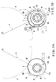
- Figs. 3A and 3B show a cylinder apparatus according to the second embodiment of the present invention.
- the second embodiment is different from the first embodiment described above in that the forward/backward moving directions of rods 12A and 12B of cylinders 11A and 11B are not parallel to a line B and that a forming direction A of an engaging surface 4c of an engaging projection 4b does not coincide with a skew direction 40 of a plate cylinder 7.
- the engaging surface 4c and an engaging surface 6c are formed on the engaging projections 4b and 6b, respectively.
- an engaging surface 30b may be formed on the abutting member 30a.
- a pin 4d standing upward from the engaging projection 4b of the inner bearing 4 abuts against the engaging surface 30b of the abutting members 30a.
- Fig. 4 shows a modification of Fig. 2B, the same applies to Fig. 2A.
- Fig. 5 shows a case in which the present invention is applied to a satellite type printing press.
- the satellite type printing press four plate cylinders 7 are arranged like satellites around a pair of blanket cylinders 8 in contact opposite to each other, to perform multicolor printing simultaneously.
- frames 1A and 1B, inner bearings 4 and 6 with engaging projections 4b and 6b, an outer bearing 3, cylinders 11A and 11B, and abutting members 30a are provided to each plate cylinder 7, the present invention can be applied to the printing press, in the same manner as described in the above embodiments.
Landscapes
- Engineering & Computer Science (AREA)
- Mechanical Engineering (AREA)
- Rotary Presses (AREA)
- Perforating, Stamping-Out Or Severing By Means Other Than Cutting (AREA)
Abstract
Description
Claims (10)
- A cylinder apparatus for a rotary printing press, characterized by comprising:a pair of first eccentric bearings (4, 6) for rotatatively supporting two ends (7A, 7B) of at least one first cylinder (7), said first eccentric bearings having abutting portions (4b, 6b, 6d);a second eccentric bearing (3) for pivotally supporting one (4) of said first eccentric bearings;a pair of support members (1A, 1B) arranged to oppose each other through a predetermined distance and adapted to pivotally support said second eccentric bearing and the other one (6) of said first eccentric bearings;a pair of first driving means (11A, 11B) for pivoting said first eccentric bearings supported by one (1B) of said support members and said second eccentric bearing;second driving means (15) for pivoting said second eccentric bearing supported by the other one (1A) of said support members; anda pair of abutting members (30a) which are supported by said support members and against which said abutting portions of said first eccentric bearings abut when said first cylinder abuts against a second cylinder (8) upon driving operation of said first driving means.
- An apparatus according to claim 1, wherein said abutting portions have abutting surfaces (4c, 6c) against which said abutting members abut, and the abutting surfaces are formed in substantially the same direction as a skew direction (40) of said first cylinder.
- An apparatus according to claim 2, wherein the 'skew direction is a direction perpendicular to a line that connects axes of said first and second cylinders.
- An apparatus according to claim 1, wherein said abutting members have abutting surfaces (30b) against which the abutting portions abut, and the abutting surfaces are formed in substantially the same direction as a skew direction (40) of said first cylinder.
- An apparatus according to claim 4, wherein the skew direction is a direction perpendicular to a line that connects axes of said first and second cylinders.
- An apparatus according to claim 1, wherein an urging portion (42) from one of said first eccentric bearings toward said second eccentric bearing and an urging portion (43) from said second eccentric bearing toward the other one of said support members are substantially located on a line that connects two axes of said first and second cylinders.
- An apparatus according to claim 6, wherein an urging portion (44) from the other one of said first eccentric bearings toward the other one of said support members is substantially located on a line that connects the two axes of said first and second cylinders.
- An apparatus according to claim 1, whereinthe abutting portions comprise engaging projections projecting from outer surfaces of said first eccentric bearings,said abutting members comprises eccentric cams, andwhen said eccentric cams are pivotally adjusted, abutting positions where the engaging projections and said eccentric cams abut change to adjust a nip pressure between said first and second cylinders.
- An apparatus according to claim 1, whereinsaid first cylinder comprises a plurality of first cylinders arranged around said second cylinder, andsaid first eccentric bearings with the abutting portions, said second eccentric bearing, said support members, said first and second driving means, and said abutting portions are provided to correspond to each of said plurality of first cylinders.
- An apparatus according to claim 1, wherein said first cylinder is a plate cylinder, and said second cylinder is a blanket cylinder.
Applications Claiming Priority (2)
| Application Number | Priority Date | Filing Date | Title |
|---|---|---|---|
| JP2000189457 | 2000-06-23 | ||
| JP2000189457A JP4611493B2 (en) | 2000-06-23 | 2000-06-23 | Rotary printing press cylinder |
Publications (3)
| Publication Number | Publication Date |
|---|---|
| EP1167027A2 true EP1167027A2 (en) | 2002-01-02 |
| EP1167027A3 EP1167027A3 (en) | 2004-01-14 |
| EP1167027B1 EP1167027B1 (en) | 2007-08-15 |
Family
ID=18689086
Family Applications (1)
| Application Number | Title | Priority Date | Filing Date |
|---|---|---|---|
| EP01114483A Expired - Lifetime EP1167027B1 (en) | 2000-06-23 | 2001-06-15 | Cylinder apparatus for a rotary printing press |
Country Status (6)
| Country | Link |
|---|---|
| US (1) | US6601504B2 (en) |
| EP (1) | EP1167027B1 (en) |
| JP (1) | JP4611493B2 (en) |
| AT (1) | ATE369981T1 (en) |
| DE (1) | DE60129886T2 (en) |
| ES (1) | ES2291247T3 (en) |
Families Citing this family (6)
| Publication number | Priority date | Publication date | Assignee | Title |
|---|---|---|---|---|
| US6886458B1 (en) * | 2003-12-18 | 2005-05-03 | Shinohara Machinery Co., Ltd. | Apparatus for adjusting printing pressure of satellite-type printing press |
| WO2006123728A1 (en) * | 2005-05-20 | 2006-11-23 | Komori Corporation | Register adjusting device of rotary body |
| JP2009000883A (en) | 2007-06-21 | 2009-01-08 | Komori Corp | Printing quality control method and apparatus for printing press |
| JP2009000881A (en) | 2007-06-21 | 2009-01-08 | Komori Corp | Printing quality control method and apparatus for relief printing press |
| DE102009055655A1 (en) * | 2009-11-24 | 2011-05-26 | Schaeffler Technologies Gmbh & Co. Kg | Eccentric adjustment on bearings of printing presses |
| JP6418630B2 (en) * | 2014-05-14 | 2018-11-07 | 株式会社小森コーポレーション | Printing machine cylinder |
Family Cites Families (15)
| Publication number | Priority date | Publication date | Assignee | Title |
|---|---|---|---|---|
| US2986086A (en) * | 1959-02-27 | 1961-05-30 | Miller Printing Machinery Co | Antifriction eccentric journaling mounting for rotatable member |
| US3786749A (en) * | 1972-04-07 | 1974-01-22 | Rockwell International Corp | Printing press cylinder support and control |
| DD125630A1 (en) * | 1976-05-13 | 1977-05-04 | ||
| DE2725030C3 (en) * | 1977-06-03 | 1982-01-07 | M.A.N. Maschinenfabrik Augsburg-Nürnberg AG, 8900 Augsburg | Changeover device for a convertible satellite printing unit |
| US4458591A (en) * | 1982-09-30 | 1984-07-10 | Harris Graphics Corporation | Rotary printing press |
| JPS59142148A (en) * | 1983-02-03 | 1984-08-15 | Komori Printing Mach Co Ltd | Print varnishing equipment |
| JPS59142150A (en) * | 1983-02-03 | 1984-08-15 | Komori Printing Mach Co Ltd | Varnish coater for print |
| DE3412812C1 (en) * | 1984-04-05 | 1985-06-27 | M.A.N.- Roland Druckmaschinen AG, 6050 Offenbach | Switching device for the blanket cylinders of a printing unit for a web-fed offset printing machine |
| DE3614027A1 (en) * | 1986-04-25 | 1987-10-29 | Roland Man Druckmasch | ACTUATING DEVICE FOR FIVE-CYLINDER PRINTING UNITS FROM OFFSET ROTATIONAL PRINTING MACHINES |
| JPS6442135A (en) | 1987-08-07 | 1989-02-14 | Mitsubishi Electric Corp | Semiconductor device |
| JP2524289Y2 (en) | 1991-05-15 | 1997-01-29 | 株式会社小森コーポレーション | Printing cylinder printing pressure adjustment device |
| DE9115598U1 (en) * | 1991-09-09 | 1992-04-23 | Koenig & Bauer AG, 8700 Würzburg | Arrangement for adjusting eccentric bushings for cylinders of printing machines |
| DE19515692A1 (en) * | 1995-04-28 | 1996-10-31 | Heidelberger Druckmasch Ag | Adjusting device for a blanket cylinder |
| US5722323A (en) * | 1995-09-13 | 1998-03-03 | Goss Graphic Systems, Inc. | Blanket cylinder throw-off device |
| US6347585B1 (en) * | 1998-08-04 | 2002-02-19 | Goss Graphic Systems, Inc. | Variable gap stabilizer |
-
2000
- 2000-06-23 JP JP2000189457A patent/JP4611493B2/en not_active Expired - Fee Related
-
2001
- 2001-06-15 EP EP01114483A patent/EP1167027B1/en not_active Expired - Lifetime
- 2001-06-15 ES ES01114483T patent/ES2291247T3/en not_active Expired - Lifetime
- 2001-06-15 DE DE60129886T patent/DE60129886T2/en not_active Expired - Lifetime
- 2001-06-15 AT AT01114483T patent/ATE369981T1/en not_active IP Right Cessation
- 2001-06-25 US US09/892,032 patent/US6601504B2/en not_active Expired - Lifetime
Also Published As
| Publication number | Publication date |
|---|---|
| US20010054361A1 (en) | 2001-12-27 |
| ES2291247T3 (en) | 2008-03-01 |
| EP1167027A3 (en) | 2004-01-14 |
| EP1167027B1 (en) | 2007-08-15 |
| JP4611493B2 (en) | 2011-01-12 |
| ATE369981T1 (en) | 2007-09-15 |
| DE60129886T2 (en) | 2008-04-30 |
| US6601504B2 (en) | 2003-08-05 |
| DE60129886D1 (en) | 2007-09-27 |
| JP2002001904A (en) | 2002-01-08 |
Similar Documents
| Publication | Publication Date | Title |
|---|---|---|
| US7146907B2 (en) | Bearing support system for a printing press having cantilevered cylinders | |
| US8042467B2 (en) | Printing press with bearer rings | |
| US4524712A (en) | Varnish coater for printed product | |
| US5813335A (en) | Apparatus for preventing backlash between the meshing teeth of a first and a second gear in a printing unit of a lithographic rotary printing press | |
| US3366047A (en) | Skewing arrangement for plate cylinder and form rollers in printing press | |
| EP1167027B1 (en) | Cylinder apparatus for a rotary printing press | |
| US4493257A (en) | Inker for a printing press | |
| DE4012928C2 (en) | Sheet transport drum for skew register correction | |
| JPH05200972A (en) | Method and apparatus for adjusting an eccentric bush for a printing press cylinder | |
| EP1882590A1 (en) | Register adjusting device of rotary body | |
| JP2000033686A (en) | Printing press especially printer for offset rotary press | |
| US4739703A (en) | Inking apparatus for printing press with vibrating form roller | |
| JPH09210143A (en) | Gear transmission | |
| JP2003514696A (en) | Rotary printing press cylinder support | |
| US5590597A (en) | Tapered bearing housing sleeves | |
| EP0719212B1 (en) | Inker mechanism | |
| JPH09177903A (en) | Play removing device in printer | |
| EP0313702B1 (en) | Inking apparatus for printing press | |
| JP2002018778A (en) | Printing sheet processing machine | |
| US5836246A (en) | Printing press | |
| GB2096543A (en) | Adjustments in printing presses | |
| JPH05138852A (en) | Bb type printing press having split plate cylinder | |
| EP0056532B1 (en) | Method and means for diagonal adjustment in an offset-printing machine, and printing machine produced with said means | |
| JPS6250137A (en) | Plate cylinder of printing press | |
| JPH09272196A (en) | Ink device for printer |
Legal Events
| Date | Code | Title | Description |
|---|---|---|---|
| PUAI | Public reference made under article 153(3) epc to a published international application that has entered the european phase |
Free format text: ORIGINAL CODE: 0009012 |
|
| AK | Designated contracting states |
Kind code of ref document: A2 Designated state(s): AT BE CH CY DE DK ES FI FR GB GR IE IT LI LU MC NL PT SE TR |
|
| AX | Request for extension of the european patent |
Free format text: AL;LT;LV;MK;RO;SI |
|
| PUAL | Search report despatched |
Free format text: ORIGINAL CODE: 0009013 |
|
| AK | Designated contracting states |
Kind code of ref document: A3 Designated state(s): AT BE CH CY DE DK ES FI FR GB GR IE IT LI LU MC NL PT SE TR |
|
| AX | Request for extension of the european patent |
Extension state: AL LT LV MK RO SI |
|
| 17P | Request for examination filed |
Effective date: 20040621 |
|
| AKX | Designation fees paid |
Designated state(s): AT BE CH CY DE DK ES FI FR GB GR IE IT LI LU MC NL PT SE TR |
|
| RTI1 | Title (correction) |
Free format text: CYLINDER APPARATUS FOR A ROTARY PRINTING PRESS |
|
| GRAP | Despatch of communication of intention to grant a patent |
Free format text: ORIGINAL CODE: EPIDOSNIGR1 |
|
| GRAS | Grant fee paid |
Free format text: ORIGINAL CODE: EPIDOSNIGR3 |
|
| GRAA | (expected) grant |
Free format text: ORIGINAL CODE: 0009210 |
|
| AK | Designated contracting states |
Kind code of ref document: B1 Designated state(s): AT BE CH CY DE DK ES FI FR GB GR IE IT LI LU MC NL PT SE TR |
|
| REG | Reference to a national code |
Ref country code: GB Ref legal event code: FG4D |
|
| REG | Reference to a national code |
Ref country code: CH Ref legal event code: EP |
|
| REG | Reference to a national code |
Ref country code: IE Ref legal event code: FG4D |
|
| REF | Corresponds to: |
Ref document number: 60129886 Country of ref document: DE Date of ref document: 20070927 Kind code of ref document: P |
|
| ET | Fr: translation filed | ||
| REG | Reference to a national code |
Ref country code: SE Ref legal event code: TRGR |
|
| REG | Reference to a national code |
Ref country code: CH Ref legal event code: NV Representative=s name: LUCHS & PARTNER PATENTANWAELTE |
|
| PG25 | Lapsed in a contracting state [announced via postgrant information from national office to epo] |
Ref country code: FI Free format text: LAPSE BECAUSE OF FAILURE TO SUBMIT A TRANSLATION OF THE DESCRIPTION OR TO PAY THE FEE WITHIN THE PRESCRIBED TIME-LIMIT Effective date: 20070815 |
|
| PG25 | Lapsed in a contracting state [announced via postgrant information from national office to epo] |
Ref country code: AT Free format text: LAPSE BECAUSE OF FAILURE TO SUBMIT A TRANSLATION OF THE DESCRIPTION OR TO PAY THE FEE WITHIN THE PRESCRIBED TIME-LIMIT Effective date: 20070815 |
|
| REG | Reference to a national code |
Ref country code: ES Ref legal event code: FG2A Ref document number: 2291247 Country of ref document: ES Kind code of ref document: T3 |
|
| PG25 | Lapsed in a contracting state [announced via postgrant information from national office to epo] |
Ref country code: BE Free format text: LAPSE BECAUSE OF FAILURE TO SUBMIT A TRANSLATION OF THE DESCRIPTION OR TO PAY THE FEE WITHIN THE PRESCRIBED TIME-LIMIT Effective date: 20070815 |
|
| PG25 | Lapsed in a contracting state [announced via postgrant information from national office to epo] |
Ref country code: GR Free format text: LAPSE BECAUSE OF FAILURE TO SUBMIT A TRANSLATION OF THE DESCRIPTION OR TO PAY THE FEE WITHIN THE PRESCRIBED TIME-LIMIT Effective date: 20071116 Ref country code: DK Free format text: LAPSE BECAUSE OF FAILURE TO SUBMIT A TRANSLATION OF THE DESCRIPTION OR TO PAY THE FEE WITHIN THE PRESCRIBED TIME-LIMIT Effective date: 20070815 |
|
| PG25 | Lapsed in a contracting state [announced via postgrant information from national office to epo] |
Ref country code: PT Free format text: LAPSE BECAUSE OF FAILURE TO SUBMIT A TRANSLATION OF THE DESCRIPTION OR TO PAY THE FEE WITHIN THE PRESCRIBED TIME-LIMIT Effective date: 20080115 |
|
| PLBE | No opposition filed within time limit |
Free format text: ORIGINAL CODE: 0009261 |
|
| STAA | Information on the status of an ep patent application or granted ep patent |
Free format text: STATUS: NO OPPOSITION FILED WITHIN TIME LIMIT |
|
| 26N | No opposition filed |
Effective date: 20080516 |
|
| PG25 | Lapsed in a contracting state [announced via postgrant information from national office to epo] |
Ref country code: MC Free format text: LAPSE BECAUSE OF NON-PAYMENT OF DUE FEES Effective date: 20080630 |
|
| PG25 | Lapsed in a contracting state [announced via postgrant information from national office to epo] |
Ref country code: IE Free format text: LAPSE BECAUSE OF NON-PAYMENT OF DUE FEES Effective date: 20080616 |
|
| PG25 | Lapsed in a contracting state [announced via postgrant information from national office to epo] |
Ref country code: CY Free format text: LAPSE BECAUSE OF FAILURE TO SUBMIT A TRANSLATION OF THE DESCRIPTION OR TO PAY THE FEE WITHIN THE PRESCRIBED TIME-LIMIT Effective date: 20070815 |
|
| PGFP | Annual fee paid to national office [announced via postgrant information from national office to epo] |
Ref country code: NL Payment date: 20090615 Year of fee payment: 9 |
|
| PGFP | Annual fee paid to national office [announced via postgrant information from national office to epo] |
Ref country code: IT Payment date: 20090617 Year of fee payment: 9 Ref country code: SE Payment date: 20090605 Year of fee payment: 9 |
|
| PGFP | Annual fee paid to national office [announced via postgrant information from national office to epo] |
Ref country code: ES Payment date: 20090710 Year of fee payment: 9 |
|
| PGFP | Annual fee paid to national office [announced via postgrant information from national office to epo] |
Ref country code: GB Payment date: 20090610 Year of fee payment: 9 |
|
| PG25 | Lapsed in a contracting state [announced via postgrant information from national office to epo] |
Ref country code: LU Free format text: LAPSE BECAUSE OF NON-PAYMENT OF DUE FEES Effective date: 20080615 |
|
| PG25 | Lapsed in a contracting state [announced via postgrant information from national office to epo] |
Ref country code: TR Free format text: LAPSE BECAUSE OF FAILURE TO SUBMIT A TRANSLATION OF THE DESCRIPTION OR TO PAY THE FEE WITHIN THE PRESCRIBED TIME-LIMIT Effective date: 20070815 |
|
| REG | Reference to a national code |
Ref country code: NL Ref legal event code: V1 Effective date: 20110101 |
|
| EUG | Se: european patent has lapsed | ||
| GBPC | Gb: european patent ceased through non-payment of renewal fee |
Effective date: 20100615 |
|
| REG | Reference to a national code |
Ref country code: FR Ref legal event code: ST Effective date: 20110228 |
|
| PG25 | Lapsed in a contracting state [announced via postgrant information from national office to epo] |
Ref country code: IT Free format text: LAPSE BECAUSE OF NON-PAYMENT OF DUE FEES Effective date: 20100615 |
|
| PG25 | Lapsed in a contracting state [announced via postgrant information from national office to epo] |
Ref country code: NL Free format text: LAPSE BECAUSE OF NON-PAYMENT OF DUE FEES Effective date: 20110101 Ref country code: FR Free format text: LAPSE BECAUSE OF NON-PAYMENT OF DUE FEES Effective date: 20100630 |
|
| REG | Reference to a national code |
Ref country code: ES Ref legal event code: FD2A Effective date: 20110714 |
|
| PG25 | Lapsed in a contracting state [announced via postgrant information from national office to epo] |
Ref country code: GB Free format text: LAPSE BECAUSE OF NON-PAYMENT OF DUE FEES Effective date: 20100615 Ref country code: ES Free format text: LAPSE BECAUSE OF NON-PAYMENT OF DUE FEES Effective date: 20110704 |
|
| PG25 | Lapsed in a contracting state [announced via postgrant information from national office to epo] |
Ref country code: ES Free format text: LAPSE BECAUSE OF NON-PAYMENT OF DUE FEES Effective date: 20100616 |
|
| PG25 | Lapsed in a contracting state [announced via postgrant information from national office to epo] |
Ref country code: SE Free format text: LAPSE BECAUSE OF NON-PAYMENT OF DUE FEES Effective date: 20100616 |
|
| PGFP | Annual fee paid to national office [announced via postgrant information from national office to epo] |
Ref country code: FR Payment date: 20090611 Year of fee payment: 9 |
|
| PGFP | Annual fee paid to national office [announced via postgrant information from national office to epo] |
Ref country code: DE Payment date: 20190604 Year of fee payment: 19 |
|
| PGFP | Annual fee paid to national office [announced via postgrant information from national office to epo] |
Ref country code: CH Payment date: 20190614 Year of fee payment: 19 |
|
| REG | Reference to a national code |
Ref country code: DE Ref legal event code: R119 Ref document number: 60129886 Country of ref document: DE |
|
| REG | Reference to a national code |
Ref country code: CH Ref legal event code: PL |
|
| PG25 | Lapsed in a contracting state [announced via postgrant information from national office to epo] |
Ref country code: CH Free format text: LAPSE BECAUSE OF NON-PAYMENT OF DUE FEES Effective date: 20200630 Ref country code: LI Free format text: LAPSE BECAUSE OF NON-PAYMENT OF DUE FEES Effective date: 20200630 |
|
| PG25 | Lapsed in a contracting state [announced via postgrant information from national office to epo] |
Ref country code: DE Free format text: LAPSE BECAUSE OF NON-PAYMENT OF DUE FEES Effective date: 20210101 |