EP1166947A1 - Reibschweissrohrverbindung und reibgeschweisstes Gesteinsbohrwerkzeug mit Bohrflüssigkeitskanal - Google Patents
Reibschweissrohrverbindung und reibgeschweisstes Gesteinsbohrwerkzeug mit Bohrflüssigkeitskanal Download PDFInfo
- Publication number
- EP1166947A1 EP1166947A1 EP01810579A EP01810579A EP1166947A1 EP 1166947 A1 EP1166947 A1 EP 1166947A1 EP 01810579 A EP01810579 A EP 01810579A EP 01810579 A EP01810579 A EP 01810579A EP 1166947 A1 EP1166947 A1 EP 1166947A1
- Authority
- EP
- European Patent Office
- Prior art keywords
- pipe connection
- connection according
- scale
- sleeve
- scale sleeve
- Prior art date
- Legal status (The legal status is an assumption and is not a legal conclusion. Google has not performed a legal analysis and makes no representation as to the accuracy of the status listed.)
- Withdrawn
Links
Images
Classifications
-
- E—FIXED CONSTRUCTIONS
- E21—EARTH OR ROCK DRILLING; MINING
- E21B—EARTH OR ROCK DRILLING; OBTAINING OIL, GAS, WATER, SOLUBLE OR MELTABLE MATERIALS OR A SLURRY OF MINERALS FROM WELLS
- E21B17/00—Drilling rods or pipes; Flexible drill strings; Kellies; Drill collars; Sucker rods; Cables; Casings; Tubings
- E21B17/02—Couplings; joints
- E21B17/04—Couplings; joints between rod or the like and bit or between rod and rod or the like
- E21B17/046—Couplings; joints between rod or the like and bit or between rod and rod or the like with ribs, pins, or jaws, and complementary grooves or the like, e.g. bayonet catches
-
- B—PERFORMING OPERATIONS; TRANSPORTING
- B23—MACHINE TOOLS; METAL-WORKING NOT OTHERWISE PROVIDED FOR
- B23K—SOLDERING OR UNSOLDERING; WELDING; CLADDING OR PLATING BY SOLDERING OR WELDING; CUTTING BY APPLYING HEAT LOCALLY, e.g. FLAME CUTTING; WORKING BY LASER BEAM
- B23K20/00—Non-electric welding by applying impact or other pressure, with or without the application of heat, e.g. cladding or plating
- B23K20/12—Non-electric welding by applying impact or other pressure, with or without the application of heat, e.g. cladding or plating the heat being generated by friction; Friction welding
- B23K20/129—Non-electric welding by applying impact or other pressure, with or without the application of heat, e.g. cladding or plating the heat being generated by friction; Friction welding specially adapted for particular articles or work
-
- F—MECHANICAL ENGINEERING; LIGHTING; HEATING; WEAPONS; BLASTING
- F16—ENGINEERING ELEMENTS AND UNITS; GENERAL MEASURES FOR PRODUCING AND MAINTAINING EFFECTIVE FUNCTIONING OF MACHINES OR INSTALLATIONS; THERMAL INSULATION IN GENERAL
- F16L—PIPES; JOINTS OR FITTINGS FOR PIPES; SUPPORTS FOR PIPES, CABLES OR PROTECTIVE TUBING; MEANS FOR THERMAL INSULATION IN GENERAL
- F16L13/00—Non-disconnectable pipe joints, e.g. soldered, adhesive, or caulked joints
- F16L13/02—Welded joints
Definitions
- the invention relates to a friction welding pipe connection and as a further aspect Rock drilling tool with a channel extending along the tool axis for the drilling fluid for an at least partially striking abrasive material removal from Rock, such as a rock hammer drill or a rock drill bit, the Rock drilling tool made of several friction welded together Sharing.
- Rock drilling tool with a channel extending along the tool axis for the drilling fluid for an at least partially striking abrasive material removal from Rock, such as a rock hammer drill or a rock drill bit, the Rock drilling tool made of several friction welded together Sharing.
- Rock drilling tools have a hollow shaft designed as a coolant channel, which ends in nozzles in the tool head.
- Such rock drilling tools are usually used composed of several parts, especially one, often as Drill rod made tubular shaft, and one, inserted on the end face Tool head with nozzles with hard material inserts. Furthermore, the other is End of the tubular shaft usually with one for receiving in a tool holder trained insertion end connected, which is at least partially coaxially hollow is.
- the coolant channel running inside the rock drilling tool which usually has no coaxial through openings, is not in the usual way Removable material can be reworked.
- US5803187 discloses a rock drilling tool having a tool head Hard material inserts and nozzles, as well as a tubular shaft as drill rod, which in adjoin a butt region coaxially with the same inner diameter. Across this joint area is one in the interior forming the drilling fluid channel Guide sleeve arranged with its outer surface directly on both the inner Shell surface of the tubular shaft and on the inner shell surface of the tool head is applied. This guide sleeve made of Teflon is only used for coaxial guidance the boring bar and the boring head.
- the object of the invention is to realize a friction welding pipe connection without undefined protruding scale beads.
- Another aspect of the invention consists in the realization of a safe drilling medium flow for one of several Parts of existing rock drilling tool connected by friction welding.
- two are coaxially associated with one another in the joint area in the hollow interior arranged a friction sleeve welded parts of a pipe connection, which with a partial, essentially corresponding to the inner diameter of a part, Outside diameter and a partially significantly reduced outside groove diameter is at least partially non-positively connected to a part, the between the partially significantly reduced outer groove diameter of the scale sleeve and the The inner diameter of at least part of the annulus created in the joint area is filled with the scale bead created during friction welding.
- the significantly reduced outer groove diameter is advantageously 70-80% of the inner diameter of a part, creating a good compromise between the volume of the Annulus for receiving the scale bead and the inner diameter of the scale sleeve given is.
- the scale sleeve is further advantageously stepped with two of substantially the same length regions of different outer diameters each extending to the end faces executed, the tapered part forming an open groove on one side, and about two thirds of its length is force fit pressed into one part, which makes it essential reduced outer groove diameter than one-sided open outer groove over both Forms parts in the butt region, axially open on one side annular space. A possibly overflowing tinder bead thus spreads axially around the circumference.
- the scale sleeve is also advantageously made of a material with the same or higher Melting point with respect to the parts of the pipe connection, advantageously made of the same material.
- connection of the tubular shaft of a rock drilling tool is advantageous the tool head and / or with the insertion end on the end faces executed, wherein a scale sleeve is arranged in the interior of the joint area. Due to the only possible axial expansion of the scale bead in the annular space The inside diameter of the scale sleeve is definitely available and can be used as a drilling medium channel be safely taken into account when dimensioning the drilling medium flow.
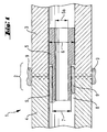
- the scale sleeve 5 is stepped with two essentially the same long, different areas each extending to the end faces Outside diameter executed, the tapered part an open on one side outer groove trained and about two thirds of its length is pressed into the part 3, whereby the significantly reduced outer groove diameter 7 as an outer groove open on one side one extends over both parts 3, 4 in the butt region 2 and the axially open on one side Forms annulus 8.
- the overflowing scale bead 9 spreads axially around the circumference out.
- the scale bead 9 formed on the outer jacket of the parts 3, 4 is through a usual material-removing post-processing step removably arranged.
- the outside groove diameter 7 is about 70-80% of the inside diameter of parts 3, 4 and Outside diameter 6, which makes a good compromise between the volume of the annulus 8 for receiving the scale bead 9 and the inner diameter 5a of the scale sleeve 5 is given.
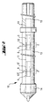
- a rock drilling tool 10 with drilling fluid channel 11 has a friction-welded one Connection to end faces 12, 12 'of a tubular shaft 13 made of steel with a tool head 14 made of steel and with an insertion end 15 made of steel, wherein in Inside the respective butting area 2, 2 ', a scale sleeve 5, 5' made of steel is arranged. Due to the only possible axial expansion of the scale bead in the annular space the inner diameter of the scale sleeve is definitely available as a drilling medium channel 11 and can be safely taken into account when dimensioning the drilling medium flow.
Landscapes
- Engineering & Computer Science (AREA)
- Mining & Mineral Resources (AREA)
- Mechanical Engineering (AREA)
- Geology (AREA)
- Life Sciences & Earth Sciences (AREA)
- Fluid Mechanics (AREA)
- Environmental & Geological Engineering (AREA)
- Physics & Mathematics (AREA)
- General Engineering & Computer Science (AREA)
- General Life Sciences & Earth Sciences (AREA)
- Geochemistry & Mineralogy (AREA)
- Earth Drilling (AREA)
- Percussive Tools And Related Accessories (AREA)
- Drilling Tools (AREA)
- Pressure Welding/Diffusion-Bonding (AREA)
Abstract
Description
Claims (10)
- Rohrverbindung zweier miteinander in einem Stossbereich (2) koaxial zugeordneter reibverschweisster Teile (3, 4) mit einem hohlen Inneren, dadurch gekennzeichnet, dass im hohlen Inneren des Stossbereiches (2) eine Zunderhülse (5) angeordnet ist.
- Rohrverbindung nach einem der vorherigen Ansprüche, dadurch gekennzeichnet, dass die Zunderhülse (5) zumindest teilweise kraftschlüssig mit dem einen Teil (3) verbunden ist.
- Rohrverbindung nach Anspruch 1 oder nach Anspruch 2, dadurch gekennzeichnet, dass die Zunderhülse (5) axial zumindest teilweise einen im wesentlichen dem Innendurchmesser eines Teils (3) entsprechenden Aussendurchmesser (6) und einem axial zumindest teilweise wesentlich verringertem Aussennutdurchmesser (7) aufweist.
- Rohrverbindung nach Anspruch 3, dadurch gekennzeichnet, dass der Aussennutdurchmesser (7) bezüglich des Innendurchmessers der Teile (3, 4) 70 - 80 % beträgt.
- Rohrverbindung nach Anspruch 3 oder nach Anspruch 4, dadurch gekennzeichnet, dass ein zwischen dem teilweise wesentlich verringertem Aussennutdurchmesser (7) der Zunderhülse (5) und dem Innendurchmesser der Teile (3, 4) im Stossbereich (2) entstandene, Ringraum (8) teilweise von dem beim Reibschweissen entstandenen Zunderwulst (9) ausgefüllt ist.
- Rohrverbindung nach Anspruch 5, dadurch gekennzeichnet, dass der Ringraum (8) einseitig axial offen ist.
- Rohrverbindung nach Anspruch 6, dadurch gekennzeichnet, dass die Zunderhülse (5) gestuft mit zwei im wesentlich gleich langen, sich jeweils bis zu den Stirnseiten erstreckenden, Bereichen unterschiedlicher Aussendurchmesser ausgeführt ist.
- Rohrverbindung nach einem der vorherigen Ansprüche, dadurch gekennzeichnet, dass die Zunderhülse (5) aus einem Material mit höherem Schmelzpunkt bezüglich des Materials der Teile (3, 4) besteht.
- Gesteinsbohrwerkzeug, welches aus einem rohrförmigen Schaft (13), einem Werkzeugkopf (14) und/oder einem Einsteckende (15) stirnseitig reibverschweisst zusammengesetzt ist, mit einem durch zumindest eine Rohrverbindung verlaufenden Bohrflüssigkeitskanal (11), dadurch gekennzeichnet, dass der Bohrflüssigkeitskanal (11) durch zumindest eine Rohrverbindung nach einem der vorherigen Ansprüche mit im Stossbereich (2, 2') angeordneter Zunderhülse (5, 5') verläuft.
- Gesteinsbohrwerkzeug nach Anspruch 9, dadurch gekennzeichnet, dass im Inneren der beiden Stossbereiches 2, 2' jeweils eine Zunderhülse 5, 5' angeordnet ist.
Applications Claiming Priority (2)
| Application Number | Priority Date | Filing Date | Title |
|---|---|---|---|
| DE10031416A DE10031416A1 (de) | 2000-06-28 | 2000-06-28 | Reibschweissrohrverbindung und reibgeschweisstes Gesteinsbohrwerkzeug mit Bohrflüssigkeitskanal |
| DE10031416 | 2000-06-28 |
Publications (1)
| Publication Number | Publication Date |
|---|---|
| EP1166947A1 true EP1166947A1 (de) | 2002-01-02 |
Family
ID=7647053
Family Applications (1)
| Application Number | Title | Priority Date | Filing Date |
|---|---|---|---|
| EP01810579A Withdrawn EP1166947A1 (de) | 2000-06-28 | 2001-06-14 | Reibschweissrohrverbindung und reibgeschweisstes Gesteinsbohrwerkzeug mit Bohrflüssigkeitskanal |
Country Status (5)
| Country | Link |
|---|---|
| EP (1) | EP1166947A1 (de) |
| JP (1) | JP2002086280A (de) |
| CN (1) | CN1329962A (de) |
| DE (1) | DE10031416A1 (de) |
| ZA (1) | ZA200105273B (de) |
Cited By (2)
| Publication number | Priority date | Publication date | Assignee | Title |
|---|---|---|---|---|
| US20140103643A1 (en) * | 2012-10-16 | 2014-04-17 | Smith International, Inc. | Friction welded heavy weight drill pipes |
| US20230130962A1 (en) * | 2021-10-22 | 2023-04-27 | Halliburton Energy Services, Inc. | Processing route to design and manufacture highly configurable non-magnetic down-hole sensor collars |
Families Citing this family (3)
| Publication number | Priority date | Publication date | Assignee | Title |
|---|---|---|---|---|
| EP2091633B1 (de) * | 2006-11-06 | 2013-01-09 | NGK Insulators, Ltd. | Herstellungsverfahren für einen verbund aus trennmembran und porösem material |
| JP5542219B1 (ja) * | 2013-01-16 | 2014-07-09 | 亞柏士氣動工具股▲分▼有限公司 | 空気動工具用シャフトの製造方法及びその製造方法によるシャフト |
| US10830025B2 (en) * | 2017-11-09 | 2020-11-10 | Baker Hughes, A Ge Company, Llc | Ultrasonic weld between components of an electrical submersible pump assembly |
Citations (7)
| Publication number | Priority date | Publication date | Assignee | Title |
|---|---|---|---|---|
| JPS5820389A (ja) * | 1981-07-31 | 1983-02-05 | Kawasaki Heavy Ind Ltd | パイプの摩擦溶接継手構造 |
| SU1393566A1 (ru) * | 1985-10-08 | 1988-05-07 | Производственное Объединение "Вильнюсский Завод Топливной Аппаратуры Им.50-Летия Ссср" | Способ шовной сварки трением |
| US4817852A (en) * | 1987-10-08 | 1989-04-04 | T. H. Industries | Method of replacing drill bit heads |
| DE3903551A1 (de) * | 1988-02-16 | 1989-08-24 | Voss Armaturen | Verbindungsteil einer leitungskupplung |
| US5395142A (en) * | 1992-05-07 | 1995-03-07 | Hmc H. Meyer & Co. Spezialstahl Gmbh | Welding joint and backing sleeve therefore |
| DE19616285C1 (de) * | 1996-04-24 | 1997-07-31 | Siemens Ag | Vorrichtung zum Fügen zweier Rohre |
| WO1998013574A1 (en) * | 1996-09-26 | 1998-04-02 | Colli Drill S.R.L. | Welded drill pipes in which the internal flash is removed and relative procedure of manufacturing |
-
2000
- 2000-06-28 DE DE10031416A patent/DE10031416A1/de not_active Withdrawn
-
2001
- 2001-06-14 EP EP01810579A patent/EP1166947A1/de not_active Withdrawn
- 2001-06-20 CN CN01121657.3A patent/CN1329962A/zh active Pending
- 2001-06-26 ZA ZA200105273A patent/ZA200105273B/xx unknown
- 2001-06-27 JP JP2001194299A patent/JP2002086280A/ja active Pending
Patent Citations (7)
| Publication number | Priority date | Publication date | Assignee | Title |
|---|---|---|---|---|
| JPS5820389A (ja) * | 1981-07-31 | 1983-02-05 | Kawasaki Heavy Ind Ltd | パイプの摩擦溶接継手構造 |
| SU1393566A1 (ru) * | 1985-10-08 | 1988-05-07 | Производственное Объединение "Вильнюсский Завод Топливной Аппаратуры Им.50-Летия Ссср" | Способ шовной сварки трением |
| US4817852A (en) * | 1987-10-08 | 1989-04-04 | T. H. Industries | Method of replacing drill bit heads |
| DE3903551A1 (de) * | 1988-02-16 | 1989-08-24 | Voss Armaturen | Verbindungsteil einer leitungskupplung |
| US5395142A (en) * | 1992-05-07 | 1995-03-07 | Hmc H. Meyer & Co. Spezialstahl Gmbh | Welding joint and backing sleeve therefore |
| DE19616285C1 (de) * | 1996-04-24 | 1997-07-31 | Siemens Ag | Vorrichtung zum Fügen zweier Rohre |
| WO1998013574A1 (en) * | 1996-09-26 | 1998-04-02 | Colli Drill S.R.L. | Welded drill pipes in which the internal flash is removed and relative procedure of manufacturing |
Non-Patent Citations (1)
| Title |
|---|
| PATENT ABSTRACTS OF JAPAN vol. 007, no. 095 (M - 209) 21 April 1983 (1983-04-21) * |
Cited By (4)
| Publication number | Priority date | Publication date | Assignee | Title |
|---|---|---|---|---|
| US20140103643A1 (en) * | 2012-10-16 | 2014-04-17 | Smith International, Inc. | Friction welded heavy weight drill pipes |
| US9816328B2 (en) * | 2012-10-16 | 2017-11-14 | Smith International, Inc. | Friction welded heavy weight drill pipes |
| US20230130962A1 (en) * | 2021-10-22 | 2023-04-27 | Halliburton Energy Services, Inc. | Processing route to design and manufacture highly configurable non-magnetic down-hole sensor collars |
| US11654506B2 (en) * | 2021-10-22 | 2023-05-23 | Halliburton Energy Services, Inc. | Processing route to design and manufacture highly configurable non-magnetic down-hole sensor collars |
Also Published As
| Publication number | Publication date |
|---|---|
| DE10031416A1 (de) | 2002-01-10 |
| JP2002086280A (ja) | 2002-03-26 |
| ZA200105273B (en) | 2002-01-14 |
| CN1329962A (zh) | 2002-01-09 |
Similar Documents
| Publication | Publication Date | Title |
|---|---|---|
| DE8630241U1 (de) | Bohrer | |
| EP0844055B1 (de) | Hohlbohrwerkzeug mit einem aus zwei koaxial zueinander angeordneten miteinander verbunden Rohren gebildeten Trägerkörper | |
| DE2201215A1 (de) | Verfahren zum Verschweissen eines Rohrs mit einer Rohrplatte | |
| CH630828A5 (de) | Tiefbohrwerkzeug. | |
| EP2087963B1 (de) | Reibschweißverfahren | |
| DE10031416A1 (de) | Reibschweissrohrverbindung und reibgeschweisstes Gesteinsbohrwerkzeug mit Bohrflüssigkeitskanal | |
| EP3558573B1 (de) | Bohrkrone mit einem spiralrohrförmigen bohrschaft und verfahren zur herstellung eines spiralrohrförmigen bohrschaftes für eine bohrkrone | |
| DE19603298A1 (de) | Bohrwerkzeug | |
| EP3501713A1 (de) | Schneidabschnitt für eine bohrkrone | |
| WO2018114242A1 (de) | Verfahren zur herstellung eines bohrschaftes für eine nassbohrkrone | |
| EP3558574B1 (de) | Bohrkrone mit einem spiralrohrförmigen bohrschaft und verfahren zur herstellung eines spiralrohrförmigen bohrschaftes für eine bohrkrone | |
| DE2541423A1 (de) | Tiefbohrwerkzeug mit einem bohrkopf und einem langen schaft | |
| DE10121986B4 (de) | Mehrschneiden-Reibahle mit innerer Kühlmittelzufuhr | |
| WO1996007011A1 (de) | Bohrkopf mit einer pfeilartigen anordnung von schneidkörpern | |
| US2267868A (en) | Method of producing drills | |
| WO2019120886A1 (de) | Verfahren zur herstellung eines schneidabschnittes für eine bohrkrone | |
| DE19625301A1 (de) | Verfahren zur Herstellung hochbelastbarer Bohrrohre | |
| EP4357056A1 (de) | Dehnspanneinrichtung und verfahren zur herstellung einer solchen dehnspanneinrichtung | |
| WO2018114241A1 (de) | Verfahren zur herstellung eines bohrschaftes für eine bohrkrone | |
| WO2019121141A1 (de) | Schneidabschnitt für eine bohrkrone | |
| WO2019121475A1 (de) | Verfahren zur herstellung eines schneidabschnittes für eine bohrkrone | |
| EP3501709A1 (de) | Schneidabschnitt für eine bohrkrone | |
| DE8908541U1 (de) | Dehnspannfutter zum Innenspannen von Rundlaufwerkzeugen | |
| WO2019121140A1 (de) | Verfahren zur herstellung eines schneidabschnittes für eine bohrkrone | |
| EP3727776A1 (de) | Schneidabschnitt für eine bohrkrone |
Legal Events
| Date | Code | Title | Description |
|---|---|---|---|
| PUAI | Public reference made under article 153(3) epc to a published international application that has entered the european phase |
Free format text: ORIGINAL CODE: 0009012 |
|
| AK | Designated contracting states |
Kind code of ref document: A1 Designated state(s): AT BE CH CY DE DK ES FI FR GB GR IE IT LI LU MC NL PT SE TR Kind code of ref document: A1 Designated state(s): CH DE FR GB LI SE |
|
| AX | Request for extension of the european patent |
Free format text: AL;LT;LV;MK;RO;SI |
|
| 17P | Request for examination filed |
Effective date: 20020702 |
|
| AKX | Designation fees paid |
Free format text: CH DE FR GB LI SE |
|
| 17Q | First examination report despatched |
Effective date: 20021121 |
|
| STAA | Information on the status of an ep patent application or granted ep patent |
Free format text: STATUS: THE APPLICATION IS DEEMED TO BE WITHDRAWN |
|
| 18D | Application deemed to be withdrawn |
Effective date: 20030402 |