EP1166005B1 - Method for joining spiral wound pipes - Google Patents
Method for joining spiral wound pipes Download PDFInfo
- Publication number
- EP1166005B1 EP1166005B1 EP00902675A EP00902675A EP1166005B1 EP 1166005 B1 EP1166005 B1 EP 1166005B1 EP 00902675 A EP00902675 A EP 00902675A EP 00902675 A EP00902675 A EP 00902675A EP 1166005 B1 EP1166005 B1 EP 1166005B1
- Authority
- EP
- European Patent Office
- Prior art keywords
- welding ring
- pipe
- pipes
- profile
- thermoplastics
- Prior art date
- Legal status (The legal status is an assumption and is not a legal conclusion. Google has not performed a legal analysis and makes no representation as to the accuracy of the status listed.)
- Expired - Lifetime
Links
- 238000000034 method Methods 0.000 title claims abstract description 28
- 238000005304 joining Methods 0.000 title claims abstract description 9
- 238000003466 welding Methods 0.000 claims abstract description 68
- 229920001169 thermoplastic Polymers 0.000 claims abstract description 33
- 239000004416 thermosoftening plastic Substances 0.000 claims abstract description 33
- 238000005520 cutting process Methods 0.000 claims abstract description 10
- 238000004804 winding Methods 0.000 claims abstract description 9
- 238000003825 pressing Methods 0.000 claims abstract description 7
- 239000000155 melt Substances 0.000 claims abstract description 4
- 239000000463 material Substances 0.000 claims description 7
- 230000008878 coupling Effects 0.000 claims description 3
- 238000010168 coupling process Methods 0.000 claims description 3
- 238000005859 coupling reaction Methods 0.000 claims description 3
- 238000010438 heat treatment Methods 0.000 claims description 3
- 239000004033 plastic Substances 0.000 claims 3
- 229920003023 plastic Polymers 0.000 claims 3
- 239000012815 thermoplastic material Substances 0.000 abstract 2
- 238000001816 cooling Methods 0.000 abstract 1
- 230000001419 dependent effect Effects 0.000 description 1
- 230000001788 irregular Effects 0.000 description 1
Images



Classifications
-
- B—PERFORMING OPERATIONS; TRANSPORTING
- B29—WORKING OF PLASTICS; WORKING OF SUBSTANCES IN A PLASTIC STATE IN GENERAL
- B29C—SHAPING OR JOINING OF PLASTICS; SHAPING OF MATERIAL IN A PLASTIC STATE, NOT OTHERWISE PROVIDED FOR; AFTER-TREATMENT OF THE SHAPED PRODUCTS, e.g. REPAIRING
- B29C65/00—Joining or sealing of preformed parts, e.g. welding of plastics materials; Apparatus therefor
- B29C65/02—Joining or sealing of preformed parts, e.g. welding of plastics materials; Apparatus therefor by heating, with or without pressure
- B29C65/34—Joining or sealing of preformed parts, e.g. welding of plastics materials; Apparatus therefor by heating, with or without pressure using heated elements which remain in the joint, e.g. "verlorenes Schweisselement"
- B29C65/3472—Joining or sealing of preformed parts, e.g. welding of plastics materials; Apparatus therefor by heating, with or without pressure using heated elements which remain in the joint, e.g. "verlorenes Schweisselement" characterised by the composition of the heated elements which remain in the joint
- B29C65/3476—Joining or sealing of preformed parts, e.g. welding of plastics materials; Apparatus therefor by heating, with or without pressure using heated elements which remain in the joint, e.g. "verlorenes Schweisselement" characterised by the composition of the heated elements which remain in the joint being metallic
- B29C65/348—Joining or sealing of preformed parts, e.g. welding of plastics materials; Apparatus therefor by heating, with or without pressure using heated elements which remain in the joint, e.g. "verlorenes Schweisselement" characterised by the composition of the heated elements which remain in the joint being metallic with a polymer coating
-
- B—PERFORMING OPERATIONS; TRANSPORTING
- B29—WORKING OF PLASTICS; WORKING OF SUBSTANCES IN A PLASTIC STATE IN GENERAL
- B29C—SHAPING OR JOINING OF PLASTICS; SHAPING OF MATERIAL IN A PLASTIC STATE, NOT OTHERWISE PROVIDED FOR; AFTER-TREATMENT OF THE SHAPED PRODUCTS, e.g. REPAIRING
- B29C65/00—Joining or sealing of preformed parts, e.g. welding of plastics materials; Apparatus therefor
- B29C65/02—Joining or sealing of preformed parts, e.g. welding of plastics materials; Apparatus therefor by heating, with or without pressure
- B29C65/34—Joining or sealing of preformed parts, e.g. welding of plastics materials; Apparatus therefor by heating, with or without pressure using heated elements which remain in the joint, e.g. "verlorenes Schweisselement"
- B29C65/3404—Joining or sealing of preformed parts, e.g. welding of plastics materials; Apparatus therefor by heating, with or without pressure using heated elements which remain in the joint, e.g. "verlorenes Schweisselement" characterised by the type of heated elements which remain in the joint
- B29C65/342—Joining or sealing of preformed parts, e.g. welding of plastics materials; Apparatus therefor by heating, with or without pressure using heated elements which remain in the joint, e.g. "verlorenes Schweisselement" characterised by the type of heated elements which remain in the joint comprising at least a single wire, e.g. in the form of a winding
-
- B—PERFORMING OPERATIONS; TRANSPORTING
- B29—WORKING OF PLASTICS; WORKING OF SUBSTANCES IN A PLASTIC STATE IN GENERAL
- B29C—SHAPING OR JOINING OF PLASTICS; SHAPING OF MATERIAL IN A PLASTIC STATE, NOT OTHERWISE PROVIDED FOR; AFTER-TREATMENT OF THE SHAPED PRODUCTS, e.g. REPAIRING
- B29C65/00—Joining or sealing of preformed parts, e.g. welding of plastics materials; Apparatus therefor
- B29C65/78—Means for handling the parts to be joined, e.g. for making containers or hollow articles, e.g. means for handling sheets, plates, web-like materials, tubular articles, hollow articles or elements to be joined therewith; Means for discharging the joined articles from the joining apparatus
- B29C65/7802—Positioning the parts to be joined, e.g. aligning, indexing or centring
-
- B—PERFORMING OPERATIONS; TRANSPORTING
- B29—WORKING OF PLASTICS; WORKING OF SUBSTANCES IN A PLASTIC STATE IN GENERAL
- B29C—SHAPING OR JOINING OF PLASTICS; SHAPING OF MATERIAL IN A PLASTIC STATE, NOT OTHERWISE PROVIDED FOR; AFTER-TREATMENT OF THE SHAPED PRODUCTS, e.g. REPAIRING
- B29C66/00—General aspects of processes or apparatus for joining preformed parts
- B29C66/01—General aspects dealing with the joint area or with the area to be joined
- B29C66/05—Particular design of joint configurations
- B29C66/10—Particular design of joint configurations particular design of the joint cross-sections
- B29C66/12—Joint cross-sections combining only two joint-segments; Tongue and groove joints; Tenon and mortise joints; Stepped joint cross-sections
- B29C66/128—Stepped joint cross-sections
- B29C66/1282—Stepped joint cross-sections comprising at least one overlap joint-segment
- B29C66/12821—Stepped joint cross-sections comprising at least one overlap joint-segment comprising at least two overlap joint-segments
-
- B—PERFORMING OPERATIONS; TRANSPORTING
- B29—WORKING OF PLASTICS; WORKING OF SUBSTANCES IN A PLASTIC STATE IN GENERAL
- B29C—SHAPING OR JOINING OF PLASTICS; SHAPING OF MATERIAL IN A PLASTIC STATE, NOT OTHERWISE PROVIDED FOR; AFTER-TREATMENT OF THE SHAPED PRODUCTS, e.g. REPAIRING
- B29C66/00—General aspects of processes or apparatus for joining preformed parts
- B29C66/01—General aspects dealing with the joint area or with the area to be joined
- B29C66/05—Particular design of joint configurations
- B29C66/10—Particular design of joint configurations particular design of the joint cross-sections
- B29C66/12—Joint cross-sections combining only two joint-segments; Tongue and groove joints; Tenon and mortise joints; Stepped joint cross-sections
- B29C66/128—Stepped joint cross-sections
- B29C66/1286—Stepped joint cross-sections comprising at least one bevelled joint-segment
-
- B—PERFORMING OPERATIONS; TRANSPORTING
- B29—WORKING OF PLASTICS; WORKING OF SUBSTANCES IN A PLASTIC STATE IN GENERAL
- B29C—SHAPING OR JOINING OF PLASTICS; SHAPING OF MATERIAL IN A PLASTIC STATE, NOT OTHERWISE PROVIDED FOR; AFTER-TREATMENT OF THE SHAPED PRODUCTS, e.g. REPAIRING
- B29C66/00—General aspects of processes or apparatus for joining preformed parts
- B29C66/50—General aspects of joining tubular articles; General aspects of joining long products, i.e. bars or profiled elements; General aspects of joining single elements to tubular articles, hollow articles or bars; General aspects of joining several hollow-preforms to form hollow or tubular articles
- B29C66/51—Joining tubular articles, profiled elements or bars; Joining single elements to tubular articles, hollow articles or bars; Joining several hollow-preforms to form hollow or tubular articles
- B29C66/52—Joining tubular articles, bars or profiled elements
- B29C66/522—Joining tubular articles
- B29C66/5221—Joining tubular articles for forming coaxial connections, i.e. the tubular articles to be joined forming a zero angle relative to each other
-
- B—PERFORMING OPERATIONS; TRANSPORTING
- B29—WORKING OF PLASTICS; WORKING OF SUBSTANCES IN A PLASTIC STATE IN GENERAL
- B29C—SHAPING OR JOINING OF PLASTICS; SHAPING OF MATERIAL IN A PLASTIC STATE, NOT OTHERWISE PROVIDED FOR; AFTER-TREATMENT OF THE SHAPED PRODUCTS, e.g. REPAIRING
- B29C66/00—General aspects of processes or apparatus for joining preformed parts
- B29C66/50—General aspects of joining tubular articles; General aspects of joining long products, i.e. bars or profiled elements; General aspects of joining single elements to tubular articles, hollow articles or bars; General aspects of joining several hollow-preforms to form hollow or tubular articles
- B29C66/63—Internally supporting the article during joining
-
- B—PERFORMING OPERATIONS; TRANSPORTING
- B29—WORKING OF PLASTICS; WORKING OF SUBSTANCES IN A PLASTIC STATE IN GENERAL
- B29C—SHAPING OR JOINING OF PLASTICS; SHAPING OF MATERIAL IN A PLASTIC STATE, NOT OTHERWISE PROVIDED FOR; AFTER-TREATMENT OF THE SHAPED PRODUCTS, e.g. REPAIRING
- B29C53/00—Shaping by bending, folding, twisting, straightening or flattening; Apparatus therefor
- B29C53/56—Winding and joining, e.g. winding spirally
- B29C53/58—Winding and joining, e.g. winding spirally helically
-
- B—PERFORMING OPERATIONS; TRANSPORTING
- B29—WORKING OF PLASTICS; WORKING OF SUBSTANCES IN A PLASTIC STATE IN GENERAL
- B29C—SHAPING OR JOINING OF PLASTICS; SHAPING OF MATERIAL IN A PLASTIC STATE, NOT OTHERWISE PROVIDED FOR; AFTER-TREATMENT OF THE SHAPED PRODUCTS, e.g. REPAIRING
- B29C65/00—Joining or sealing of preformed parts, e.g. welding of plastics materials; Apparatus therefor
- B29C65/02—Joining or sealing of preformed parts, e.g. welding of plastics materials; Apparatus therefor by heating, with or without pressure
- B29C65/34—Joining or sealing of preformed parts, e.g. welding of plastics materials; Apparatus therefor by heating, with or without pressure using heated elements which remain in the joint, e.g. "verlorenes Schweisselement"
- B29C65/3468—Joining or sealing of preformed parts, e.g. welding of plastics materials; Apparatus therefor by heating, with or without pressure using heated elements which remain in the joint, e.g. "verlorenes Schweisselement" characterised by the means for supplying heat to said heated elements which remain in the join, e.g. special electrical connectors of windings
-
- B—PERFORMING OPERATIONS; TRANSPORTING
- B29—WORKING OF PLASTICS; WORKING OF SUBSTANCES IN A PLASTIC STATE IN GENERAL
- B29L—INDEXING SCHEME ASSOCIATED WITH SUBCLASS B29C, RELATING TO PARTICULAR ARTICLES
- B29L2024/00—Articles with hollow walls
Definitions
- This invention relates to a method for joining thermoplastics pipes made by spiral winding of a hollow profile with mainly rectangular cross section, wherein the ends of the thermoplastics pipes are prepared by closing end opening of the hollow profile so that the pipe receives an even stair like end surface, after which the pipes to be joined are positioned aligned with each other.
- preparing of the pipe end comprises cutting of the profile in the end of the pipe along inside of a side wall that is fastened to nearest preceding wound round resulting in an end surface with a double wall thickness, and cutting of the end of the profile with a section in a right or an obtuse angle, of equal size for all of the ends of the pipes to be joined together, a disc-formed welding ring, matching with the inner and outer diameters of the pipes, is inserted in the slot between the two pipes, which welding ring comprises at least one loop of a resistance wire covered by a thermoplastics sleeve, the two pipes are centered with an inner root support and an outer root support around the seam with the welding ring, the pipe ends are pressed together against each other, the resistance wire of the welding ring is connected to a current source for heating the thermoplastics material in the welding ring and the pipe ends so that the thermoplastics material melts down and forms a welding seam
- thermoplastic pipes 1 that are made by spiral winding a hollow profile 2 with a mainly rectangular cross section, and by welding together every wound round to the nearest located preceding wound round, are joined together in accordance with this invention in the following way:
- the pipe ends to be joined together are cut along the inside of the side wall of the spiral wound profile 2 that is fastened to the nearest preceding wound round of the profile, mainly around the entire periphery of the pipe and with a section 3 that cuts the end of the profile 2 in a right or obtuse angle ⁇ which angle has to be of equal size for both pipe ends.
- the hole in the cut end of the profile 2 is closed with thermoplastics material and the entire pipe end surface is prepared to present an even surface.
- the two pipes 1 are positioned aligned with each other and carried by adjustable pipe supports 4, so that the cut profile ends 3 are set axially offset in relation to each other.
- a disc-formed welding ring 5 is inserted in the slot between the two pipe ends.
- the welding ring 5 comprises at least one loop of a resistance wire 6 covered by a thermoplastics sleeve 7. Thereafter, the pipe ends are aligned, using an inner root support 8 and an outer root support 9 around the seam with the welding ring 5. These root supports 8, 9 ensure that an absolutely even seam surface is obtained and, at the same time, they prevent the resistance wire 6 of the welding ring 5 from protruding out from the seam during subsequent treatment stages.
- Both pipes 1 have beforehand been provided with a pipe clamp 10, which pipe clamps 10 are connected to each other by hydraulic cylinders 11 arranged to press the pipe ends against each other.
- the resistance wire 6 of the welding ring is connected to a current source 12 to heat the thermoplastics material in the welding ring 5 and the end surfaces of the pipes 1 so that the thermoplastics material melts down to form a welding seam, whereafter the welding seam is cooled down and the root supports 8,9 and other auxiliary accessories 10, 11 are removed from the pipe 1 welded together at the same time as the connecting wires 13 between the welding ring 5 and the current source 12 are cut off, after which the joint is completed.
- the pipe ends of the profile 2 When the ends of the profile 2 are cut with a section cutting the profile perpendicularly, the pipe ends have, in addition to a compressive force pressing the pipe ends together, also to be subjected to a torsional force, e.g. by using a torsion cylinder arrangement 14, as shown in Fig. 3, in order to obtain a necessary compressive force between the cut profile ends 3.
- the torsion cylinder arrangement 14 comprises a diagonally directed cylinder, arranged to be prestressed and fastened to one of the pipes 1, and two torsion cylinders fastened to the respective ends of said cylinder, which torsion cylinders are arranged to exert a torsion force between the both pipes 1.
- the welding ring 5 must in advance be bent so that it precisely follows the form of the pipe end with the cut profile end 3.
- the closing of the hole in the profile end 3 is carried out by using a thermoplastics plate 15 that is welded to the cut end surface 3 of the profile 2.
- extruded thermoplastics mass can be supplied to the concave angle between the cut profile end 3 provided with the thermoplastics plate 15 and the profile wall in the end surface of the pipe 1, and simultaneously the outer convex angle between said thermoplastic plate 15 and the profile wall in the end surface of the pipe 1 can be somewhat rounded off.
- the welding ring 5 used in the method in accordance with the present invention can suitably be produced by extruding a thermoplastic sleeve 7 around a painted resistance wire 6.
- the thermoplastic sleeve 7 may have a quadratic, a rectangular, as in Fig. 7, or a round profile.
- the obtained thermoplastics covered resistance wire 6 is wound spirally on a removable spool 16 (Fig.
- the welding ring 5 must be bent beforehand, this can preferably be carried out between two pressing plates 19, as indicated in Figs. 8d and 8e, which pressing plates 19 have a form matching with that of the end surfaces of the pipes to be joined together.
- the pressing results in a welding ring in accordance with Fig. 6, respectively 8f, and 8g.
- the connecting wires 13 of a welding ring 5 are mostly drawn to the outer periphery of a pipe to be joinded, especially if the pipe has a small diameter, i.e. below 800 mm. In joining pipes having a large diameter, i.e. above 800 mm both connecting wires 13 of the welding ring 5 may preferably be drawn to the inner periphery of the pipe. Also by joining pipes having a small diameter it may be preferable to draw both connecting wires to the inner periphery of the pipe, especially during severe conditions.
- the welding ring 5 may be built up of two concentrically arranged discs, whereby the connecting wires 13 of the outer disc are drawn to the outer periphery of said disc, and the connecting wires 13 of the inner disc to the inner periphery of the latter.
- the welding ring 5 may comprise two separate loops of resistance wires 6, an inner and an outer, which are connected to their respective current sources, or to a current source with several outputs.
- thermoplastics covered resistance wire 6 can be double folded before winding on the spool 16. This will result in a welding ring 5 having both wire ends at its outer periphery, as shown in fig.9a.
- the welding ring 5 is built up of two thermoplastics covered resistance wires 6 and 6a as schematically shown in figure 9b. One end of both wires 6 and 6a are placed one upon another on the core of the previously mentioned removable spool 16 and both wires 6 and 6a are spirally wound on the spool and welded together as previously described.
- Such a welding ring enables the use of either the inner or the outer ends of the resistance wires 6, 6a as connecting wires whereby the opposite ends of said resistance wires 6, 6a are coupled together by a coupling means 20.
- the inner ends of the resistance wires are coupled together by the coupling means 20 and the outer ends are intended to be connected to a current source.
Landscapes
- Engineering & Computer Science (AREA)
- Mechanical Engineering (AREA)
- Lining Or Joining Of Plastics Or The Like (AREA)
- Shaping Of Tube Ends By Bending Or Straightening (AREA)
- Heat-Exchange Devices With Radiators And Conduit Assemblies (AREA)
- Branch Pipes, Bends, And The Like (AREA)
- Filling Or Discharging Of Gas Storage Vessels (AREA)
- Structures Of Non-Positive Displacement Pumps (AREA)
- Moulding By Coating Moulds (AREA)
- Windings For Motors And Generators (AREA)
Abstract
Description
- This invention relates to a method for joining thermoplastics pipes made by spiral winding of a hollow profile with mainly rectangular cross section, wherein the ends of the thermoplastics pipes are prepared by closing end opening of the hollow profile so that the pipe receives an even stair like end surface, after which the pipes to be joined are positioned aligned with each other.
- In joining together of spiral wound pipes, a lot of problems are encountered, either as a consequence of the irregular form of the pipe end with an open profile end, or due to a straightly cut pipe end with an end surface having, over most of the periphery of the pipe, a groove-formed recess passing into the helically extending channel of the profile.
- In accordance with previously known methods as, for example, the method according to Fi-A-87318, the joining together of spirally wound pipes has been carried out either by extruder welding from the inside of the pipe, or by pipe sleeve joints. All of these previously known methods tend to require relatively much work. Extruder welding also requires a relatively complicated equipment and the pipe sleeve joints often lead to problems with leaking seams.
- The objective of the present invention is to eliminate these problems. This is achieved by a method according to
claim 1, wherein
preparing of the pipe end comprises cutting of the profile in the end of the pipe along inside of a side wall that is fastened to nearest preceding wound round resulting in an end surface with a double wall thickness, and cutting of the end of the profile with a section in a right or an obtuse angle, of equal size for all of the ends of the pipes to be joined together,
a disc-formed welding ring, matching with the inner and outer diameters of the pipes, is inserted in the slot between the two pipes, which welding ring comprises at least one loop of a resistance wire covered by a thermoplastics sleeve,
the two pipes are centered with an inner root support and an outer root support around the seam with the welding ring,
the pipe ends are pressed together against each other,
the resistance wire of the welding ring is connected to a current source for heating the thermoplastics material in the welding ring and the pipe ends so that the thermoplastics material melts down and forms a welding seam,
the welding seam is cooled,
the root supports and other accessories are removed from the pipe welded together, and
the connection wires of the welding ring are cutted off. - Using this method, an elegant and simple way to join together spiral wound pipes is provided, resulting in nice, tight, and secure seams. When the outer profile is cut using the method described above, a pipe end is obtained with a double wall thickness, and this will, to a sufficient degree, maintain its rigidity even under the heating process with the welding ring, thus ensuring that a sufficient pressure force can be maintained between the end surfaces of both of the pipes to be joined together.
- Other characteristics of the invention will become evident by studying the attached,
dependent Claims 2 to 14. - The invention is described in more detail with reference to the attached drawing where
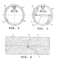
- Fig. 1 shows a principle sketch at a stage of the method in accordance with this invention, when all components are installed and before any pressure force is directed to the pipe ends,
- Fig. 2 shows an end view of the stage of the method in Fig. 1.
- Fig. 3 shows an end view of another embodyment of the method in accordance with this invention,
- Fig. 4 shows a completed joint made in accordance with this invention,
- Fig. 5 shows an example of a welding ring in accordance with this invention, seen in perspective,
- Fig. 6 shows a section A-A through the welding ring in Fig. 4 and/or Fig. 5,
- Fig. 7 shows another example of a welding ring in accordance with this invention,
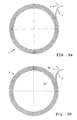
- Figs. 8a to 8g show a principle sketch of making a welding ring in accordance with Fig. 6, and
- Fig. 9a and 9b show two prefered embodyments of a welding ring.
-
- Two
thermoplastic pipes 1, that are made by spiral winding ahollow profile 2 with a mainly rectangular cross section, and by welding together every wound round to the nearest located preceding wound round, are joined together in accordance with this invention in the following way: - The pipe ends to be joined together are cut along the inside of the side wall of the
spiral wound profile 2 that is fastened to the nearest preceding wound round of the profile, mainly around the entire periphery of the pipe and with asection 3 that cuts the end of theprofile 2 in a right or obtuse angle α which angle has to be of equal size for both pipe ends. The hole in the cut end of theprofile 2 is closed with thermoplastics material and the entire pipe end surface is prepared to present an even surface. Thereafter, the twopipes 1 are positioned aligned with each other and carried by adjustable pipe supports 4, so that thecut profile ends 3 are set axially offset in relation to each other. A disc-formedwelding ring 5 is inserted in the slot between the two pipe ends. Its dimensions are matched with the inner and outer diameters of the pipe. Thewelding ring 5 comprises at least one loop of aresistance wire 6 covered by athermoplastics sleeve 7. Thereafter, the pipe ends are aligned, using aninner root support 8 and anouter root support 9 around the seam with thewelding ring 5. These root supports 8, 9 ensure that an absolutely even seam surface is obtained and, at the same time, they prevent theresistance wire 6 of thewelding ring 5 from protruding out from the seam during subsequent treatment stages. Bothpipes 1 have beforehand been provided with apipe clamp 10, whichpipe clamps 10 are connected to each other byhydraulic cylinders 11 arranged to press the pipe ends against each other. Theresistance wire 6 of the welding ring is connected to acurrent source 12 to heat the thermoplastics material in thewelding ring 5 and the end surfaces of thepipes 1 so that the thermoplastics material melts down to form a welding seam, whereafter the welding seam is cooled down and the root supports 8,9 and otherauxiliary accessories pipe 1 welded together at the same time as the connectingwires 13 between thewelding ring 5 and thecurrent source 12 are cut off, after which the joint is completed. - When the ends of the
profile 2 are cut with a section cutting the profile perpendicularly, the pipe ends have, in addition to a compressive force pressing the pipe ends together, also to be subjected to a torsional force, e.g. by using atorsion cylinder arrangement 14, as shown in Fig. 3, in order to obtain a necessary compressive force between thecut profile ends 3. Thetorsion cylinder arrangement 14 comprises a diagonally directed cylinder, arranged to be prestressed and fastened to one of thepipes 1, and two torsion cylinders fastened to the respective ends of said cylinder, which torsion cylinders are arranged to exert a torsion force between the bothpipes 1. Hereby, thewelding ring 5 must in advance be bent so that it precisely follows the form of the pipe end with thecut profile end 3. - By cutting the
profile end 3 with a section cutting theprofile 2 in an obtuse angle, such an advantage is reached that a sufficient compressive force is obtained, also between the cut profile ends, by using only thehydraulic cylinders 11, which will considerably facilitate the joining operation. The bigger the angle α is, the better the welding result will be. Very good results can be obtained if the angle α is 135° or 150°. Hereby, also fully flat, somewhatflexible welding rings 5 can be used, which completely match the form of the pipe ends, when the pipe ends are pressed together. - According to a preferred embodyment the closing of the hole in the
profile end 3 is carried out by using athermoplastics plate 15 that is welded to thecut end surface 3 of theprofile 2. To further ensure an absolute tightness of the seam, extruded thermoplastics mass can be supplied to the concave angle between thecut profile end 3 provided with thethermoplastics plate 15 and the profile wall in the end surface of thepipe 1, and simultaneously the outer convex angle between saidthermoplastic plate 15 and the profile wall in the end surface of thepipe 1 can be somewhat rounded off. - The
welding ring 5 used in the method in accordance with the present invention can suitably be produced by extruding athermoplastic sleeve 7 around a paintedresistance wire 6. Thethermoplastic sleeve 7 may have a quadratic, a rectangular, as in Fig. 7, or a round profile. The obtained thermoplastics coveredresistance wire 6 is wound spirally on a removable spool 16 (Fig. 8a) the core of which having a diameter corresponding to the inner diameter of thepipe 1 and a length corresponding to the width of the thermoplastics sleeve, theflanges 17 of which are provided with radially directedslots 18 through which the spirally wound windings of thewelding ring 5 are joined together by welds, whereby a welding ring in accordance with Figs. 5 and 8b is obtained, showing a profile in accordance with 8c. - If the
welding ring 5 must be bent beforehand, this can preferably be carried out between twopressing plates 19, as indicated in Figs. 8d and 8e, which pressingplates 19 have a form matching with that of the end surfaces of the pipes to be joined together. The pressing results in a welding ring in accordance with Fig. 6, respectively 8f, and 8g. - The connecting
wires 13 of awelding ring 5 are mostly drawn to the outer periphery of a pipe to be joinded, especially if the pipe has a small diameter, i.e. below 800 mm. In joining pipes having a large diameter, i.e. above 800 mm both connectingwires 13 of thewelding ring 5 may preferably be drawn to the inner periphery of the pipe. Also by joining pipes having a small diameter it may be preferable to draw both connecting wires to the inner periphery of the pipe, especially during severe conditions. - According to another embodyment the
welding ring 5 may be built up of two concentrically arranged discs, whereby the connectingwires 13 of the outer disc are drawn to the outer periphery of said disc, and the connectingwires 13 of the inner disc to the inner periphery of the latter. Alternatively, thewelding ring 5 may comprise two separate loops ofresistance wires 6, an inner and an outer, which are connected to their respective current sources, or to a current source with several outputs. - In order to avoid drawing of one connecting wire radially across the whole welding ring the thermoplastics covered
resistance wire 6 can be double folded before winding on thespool 16. This will result in awelding ring 5 having both wire ends at its outer periphery, as shown in fig.9a. - According to a preferred embodiment the
welding ring 5 is built up of two thermoplastics coveredresistance wires wires removable spool 16 and bothwires resistance wires resistance wires
Claims (14)
- A method for joining thermoplastics pipes (1) made by spiral winding of a hollow profile (2) with mainly rectangular cross section, wherein the ends of the thermoplastics pipes are prepared by closing end opening of the hollow profile so that the pipe receives an even stair like end surface, after which the pipes to be joined are positioned aligned with each other, wherein
preparing of the pipe end comprises cutting of the profile (2) in the end of the pipe along inside of a side wall that is fastened to nearest preceding wound round resulting in an end surface with a double wall thickness, and cutting of the end (3) of the profile with a section in a right or an obtuse angle (α), of equal size for all of the ends of the pipes to be joined together,
a disc-formed welding ring (5), matching with the inner and outer diameters of the pipes, is inserted in the slot between the two pipes (1), which welding ring comprises at least one loop of a resistance wire (6) covered by a thermoplastics sleeve (7),
the two pipes (1) are centered with an inner root support (8) and an outer root support (9) around the seam with the welding ring (5),
the pipe ends are pressed together against each other,
the resistance wire (6) of the welding ring is connected to a current source (12) for heating the thermoplastics material in the welding ring (5) and the pipe ends so that the thermoplastics material melts down and forms a welding seam,
the welding seam is cooled,
the root supports (8, 9) and other accessories (10, 11) are removed from the pipe welded together, and
the connection wires (13) of the welding ring are cutted off. - A method in accordance with Claim 1, characterized in that the angle (α) in which the profile ends are cut is 135°.
- A method in accordance with Claim 1, characterized in that the angle (α) in which the profile ends are cut is 150°.
- A method in accordance with Claim 1, characterized in that closing of the holes in the profile ends (3) is carried out by welding a plastics plate (15) on the cut profile end (3).
- A method in accordance with Claim 4, characterized in that the concave inner angle between the cut profile end (3) with the plastics plate (15) and the end surface of the pipe is supplied with extruded thermoplastics mass, and the convex outer angle between the plastics plate (15) and the end surface of the pipe is somewhat rounded off.
- A method in accordance with Claim 1, characterized in that the welding ring (5) is flexible and matches with the form of the prepared end surface of the pipe ends when the pipe ends are pressed together.
- A method in accordance with Claim 1, characterized in that the welding ring (5) is bent beforehand between two pressing plates (19) to the same form as the pipe ends to be joined together.
- A method in accordance with Claim 1, characterized in that the pipes (1) are, in addition to the force pressing them together, also exerted to a torsion force in order to obtain a compressive force between the cut profile ends (3) of the pipe ends.
- A method in accordance with Claim 1, characterized in that the welding ring (5) is manufactured by extruding a thermoplastics sleeve (7) around a painted resistance wire (6) and by spirally winding the obtained thermoplastics covered resistance wire (6) on a removable spool (16) the core of which having a diameter corresponding to the inner diameter of the pipe (1), and a length corresponding to the width of the thermoplastics sleeve (7), and the flanges (7) of which are provided with radially directed slots (18), through which the in spiral form wound rounds of the welding ring (5) are joined together with each other by welds.
- A method in accordance with Claim 9, characterized in that the connecting wires (13) of the welding ring (5) are drawn either to the outer or the inner periphery of the welding ring (5).
- A method according to Claim 9, characterized in that the welding ring (5) is built up by spirally winding two thermoplastics covered resistance wires (6,6a) simultaneously on the removable spool (16).
- A method according to claim 11, characterized in that one pair of ends of said resistance wires (6, 6a) is interconnected by means of a coupling means (20) and the opposite pair of ends is connectable to a current source (12).
- A method according to claim 9, characterized in that the thermoplastics covered resistance wire (6) is double folded before the winding on the removable spool (16).
- A method in accordance with Claim 9, characterized in that the welding ring (5) is wound by a radially inner and a radially outer profile loop (6), the connecting wires of which are led, respectively, to the inner and the outer peripheries of the welding ring (5).
Applications Claiming Priority (3)
| Application Number | Priority Date | Filing Date | Title |
|---|---|---|---|
| FI990204A FI107405B (en) | 1999-02-03 | 1999-02-03 | Method for splicing spirally wound tubes |
| FI990204 | 1999-02-03 | ||
| PCT/FI2000/000058 WO2000046540A1 (en) | 1999-02-03 | 2000-01-28 | Method for joining spiral wound pipes |
Publications (2)
| Publication Number | Publication Date |
|---|---|
| EP1166005A1 EP1166005A1 (en) | 2002-01-02 |
| EP1166005B1 true EP1166005B1 (en) | 2004-01-14 |
Family
ID=8553596
Family Applications (1)
| Application Number | Title | Priority Date | Filing Date |
|---|---|---|---|
| EP00902675A Expired - Lifetime EP1166005B1 (en) | 1999-02-03 | 2000-01-28 | Method for joining spiral wound pipes |
Country Status (15)
| Country | Link |
|---|---|
| EP (1) | EP1166005B1 (en) |
| JP (1) | JP2002536606A (en) |
| AT (1) | ATE257925T1 (en) |
| AU (1) | AU763558B2 (en) |
| CA (1) | CA2356750C (en) |
| DE (1) | DE60007728T2 (en) |
| DK (1) | DK1166005T3 (en) |
| EG (1) | EG22655A (en) |
| FI (1) | FI107405B (en) |
| HK (1) | HK1045184A1 (en) |
| MX (1) | MXPA01007237A (en) |
| PL (1) | PL193611B1 (en) |
| RU (1) | RU2230974C2 (en) |
| WO (1) | WO2000046540A1 (en) |
| ZA (1) | ZA200105487B (en) |
Cited By (1)
| Publication number | Priority date | Publication date | Assignee | Title |
|---|---|---|---|---|
| US7776248B2 (en) | 2005-03-11 | 2010-08-17 | Vinidex Pty Limited | Socketing of pipe |
Families Citing this family (5)
| Publication number | Priority date | Publication date | Assignee | Title |
|---|---|---|---|---|
| FI107522B (en) * | 1999-11-03 | 2001-08-31 | Kwh Pipe Ab Oy | Method and apparatus for producing spirally wound tubes |
| FI115484B (en) * | 2003-02-25 | 2005-05-13 | Kwh Pipe Ab Oy | The hollow profile used to make the tube |
| RU2263245C1 (en) * | 2004-09-23 | 2005-10-27 | Общество с ограниченной ответственностью "Бородино-Пласт" | Method of connection of spring-seam pipes of coiled hollow section |
| FI120824B (en) * | 2005-07-08 | 2010-03-31 | Kwh Pipe Ab Oy | Method and welding mirror for connecting pipes |
| RU2383810C2 (en) * | 2007-11-16 | 2010-03-10 | Михаил Вадимович Волков | Method for manufacturing of spiral-wound pipes from thermoplastic with hollow wall of closed profile |
Family Cites Families (6)
| Publication number | Priority date | Publication date | Assignee | Title |
|---|---|---|---|---|
| FI87318C (en) * | 1991-06-14 | 1992-12-28 | Kwh Pipe Ab Oy | Method for splicing of spirally wound thermoplastic tubes |
| FR2690036B1 (en) * | 1992-04-10 | 1998-10-09 | Gaz De France | NET FORMING RESISTANCE, ITS APPLICATION TO WELDING OF JOINTED TUBES AND TO THE CROSS CONNECTION OF PIPES, ASSEMBLIES THUS CONSTITUTED AND ELECTRICALLY WELDABLE CONNECTION SOCKET. |
| JPH06102368B2 (en) * | 1992-09-18 | 1994-12-14 | 史朗 金尾 | Corrugated spiral tube with joint, method for manufacturing the same, and method for connecting and sealing corrugated spiral tube |
| EP0927097A1 (en) * | 1995-06-28 | 1999-07-07 | Raymond Allan Goldsmid | Element for fusion welding plastics |
| DE19710790A1 (en) * | 1997-03-17 | 1998-10-08 | Festo Ag & Co | Drive device |
| DE19718790C2 (en) * | 1997-05-03 | 2001-06-28 | Tracto Technik | Pipe connection and its use |
-
1999
- 1999-02-03 FI FI990204A patent/FI107405B/en not_active IP Right Cessation
-
2000
- 2000-01-28 DE DE60007728T patent/DE60007728T2/en not_active Expired - Fee Related
- 2000-01-28 DK DK00902675T patent/DK1166005T3/en active
- 2000-01-28 EP EP00902675A patent/EP1166005B1/en not_active Expired - Lifetime
- 2000-01-28 AU AU24428/00A patent/AU763558B2/en not_active Ceased
- 2000-01-28 PL PL00349958A patent/PL193611B1/en not_active IP Right Cessation
- 2000-01-28 JP JP2000597580A patent/JP2002536606A/en active Pending
- 2000-01-28 HK HK02104885.8A patent/HK1045184A1/en unknown
- 2000-01-28 MX MXPA01007237A patent/MXPA01007237A/en unknown
- 2000-01-28 RU RU2001124355/06A patent/RU2230974C2/en not_active IP Right Cessation
- 2000-01-28 CA CA002356750A patent/CA2356750C/en not_active Expired - Fee Related
- 2000-01-28 AT AT00902675T patent/ATE257925T1/en not_active IP Right Cessation
- 2000-01-28 WO PCT/FI2000/000058 patent/WO2000046540A1/en not_active Ceased
- 2000-01-31 EG EG20000110A patent/EG22655A/en active
-
2001
- 2001-07-03 ZA ZA200105487A patent/ZA200105487B/en unknown
Cited By (1)
| Publication number | Priority date | Publication date | Assignee | Title |
|---|---|---|---|---|
| US7776248B2 (en) | 2005-03-11 | 2010-08-17 | Vinidex Pty Limited | Socketing of pipe |
Also Published As
| Publication number | Publication date |
|---|---|
| DE60007728T2 (en) | 2004-12-02 |
| JP2002536606A (en) | 2002-10-29 |
| FI990204A7 (en) | 2000-08-04 |
| RU2230974C2 (en) | 2004-06-20 |
| AU2442800A (en) | 2000-08-25 |
| DK1166005T3 (en) | 2004-05-10 |
| HK1045184A1 (en) | 2002-11-15 |
| EP1166005A1 (en) | 2002-01-02 |
| DE60007728D1 (en) | 2004-02-19 |
| FI107405B (en) | 2001-07-31 |
| CA2356750C (en) | 2007-12-04 |
| EG22655A (en) | 2003-05-31 |
| PL193611B1 (en) | 2007-02-28 |
| MXPA01007237A (en) | 2002-06-04 |
| PL349958A1 (en) | 2002-10-21 |
| ATE257925T1 (en) | 2004-01-15 |
| ZA200105487B (en) | 2002-07-03 |
| FI990204A0 (en) | 1999-02-03 |
| CA2356750A1 (en) | 2000-08-10 |
| WO2000046540A1 (en) | 2000-08-10 |
| AU763558B2 (en) | 2003-07-24 |
Similar Documents
| Publication | Publication Date | Title |
|---|---|---|
| US4449038A (en) | Apparatus for welding a joint between plastic pipes | |
| US3987276A (en) | Welded plastic attachment subassembly | |
| US5836621A (en) | Method of and joint for electrofusion coupling of thermoplastic pipes | |
| ES296146Y (en) | CONFORMED DRILLING PIECE BASED ON WELDABLE PLASTIC TO CONNECT AT LEAST ONE BIPTING PIPE TO A PIPE MADE OF WELDABLE PLASTIC | |
| GB2321616A (en) | Band joining system | |
| YU47000A (en) | Method of jointing two reinforced thermoplastics material tubes | |
| US6322653B1 (en) | Method for joining spiral wound pipes | |
| AU763558B2 (en) | Method for joining spiral wound pipes | |
| US4851647A (en) | Process for welding butt-jointed plastic tubes and welding device for performing the process | |
| US7083204B1 (en) | Composite metal pipe coupling and assembly | |
| RU2001124355A (en) | METHOD FOR CONNECTING PIPES FROM THERMOPLAST | |
| US6666945B1 (en) | Preparation of an end of a thermoplastics tube manufactured by spirally winding a hollow profile | |
| US20100213701A1 (en) | Method and device for joining pipes | |
| DK151981B (en) | PROCEDURE AND APPARATUS FOR JOINING A PIPE AND A PIPE FORM | |
| SU1742090A1 (en) | Method of pipe connection | |
| TH42024A (en) | Method for connecting spiral coiled pipes | |
| TH23015B (en) | Method for connecting spiral coiled pipes | |
| KR100523175B1 (en) | A pipe of HDPE with coupling flange and its manufacturing process | |
| JPS6018911Y2 (en) | Synthetic resin tubular body joining machine | |
| KR200322169Y1 (en) | A pipe of HDPE with coupling flange | |
| KR200207788Y1 (en) | a | |
| SU1162612A1 (en) | Method of joining plastic sleeves | |
| CA2227805A1 (en) | Method and apparatus for joining helically wound pipes |
Legal Events
| Date | Code | Title | Description |
|---|---|---|---|
| PUAI | Public reference made under article 153(3) epc to a published international application that has entered the european phase |
Free format text: ORIGINAL CODE: 0009012 |
|
| 17P | Request for examination filed |
Effective date: 20010813 |
|
| AK | Designated contracting states |
Kind code of ref document: A1 Designated state(s): AT BE CH CY DE DK ES FI FR GB GR IE IT LI LU MC NL PT SE |
|
| AX | Request for extension of the european patent |
Free format text: AL;LT;LV;MK;RO;SI |
|
| RIN1 | Information on inventor provided before grant (corrected) |
Inventor name: ANDTBACKA, ANDERS Inventor name: BLOMQVIST, GUNNAR Inventor name: SLOTTE, STEFAN |
|
| RAP1 | Party data changed (applicant data changed or rights of an application transferred) |
Owner name: OY KWH PIPE AB |
|
| GRAP | Despatch of communication of intention to grant a patent |
Free format text: ORIGINAL CODE: EPIDOSNIGR1 |
|
| GRAS | Grant fee paid |
Free format text: ORIGINAL CODE: EPIDOSNIGR3 |
|
| GRAA | (expected) grant |
Free format text: ORIGINAL CODE: 0009210 |
|
| AK | Designated contracting states |
Kind code of ref document: B1 Designated state(s): AT BE CH CY DE DK ES FI FR GB GR IE IT LI LU MC NL PT SE |
|
| PG25 | Lapsed in a contracting state [announced via postgrant information from national office to epo] |
Ref country code: IT Free format text: LAPSE BECAUSE OF FAILURE TO SUBMIT A TRANSLATION OF THE DESCRIPTION OR TO PAY THE FEE WITHIN THE PRESCRIBED TIME-LIMIT;WARNING: LAPSES OF ITALIAN PATENTS WITH EFFECTIVE DATE BEFORE 2007 MAY HAVE OCCURRED AT ANY TIME BEFORE 2007. THE CORRECT EFFECTIVE DATE MAY BE DIFFERENT FROM THE ONE RECORDED. Effective date: 20040114 Ref country code: BE Free format text: LAPSE BECAUSE OF FAILURE TO SUBMIT A TRANSLATION OF THE DESCRIPTION OR TO PAY THE FEE WITHIN THE PRESCRIBED TIME-LIMIT Effective date: 20040114 Ref country code: CY Free format text: LAPSE BECAUSE OF FAILURE TO SUBMIT A TRANSLATION OF THE DESCRIPTION OR TO PAY THE FEE WITHIN THE PRESCRIBED TIME-LIMIT Effective date: 20040114 Ref country code: NL Free format text: LAPSE BECAUSE OF FAILURE TO SUBMIT A TRANSLATION OF THE DESCRIPTION OR TO PAY THE FEE WITHIN THE PRESCRIBED TIME-LIMIT Effective date: 20040114 Ref country code: AT Free format text: LAPSE BECAUSE OF FAILURE TO SUBMIT A TRANSLATION OF THE DESCRIPTION OR TO PAY THE FEE WITHIN THE PRESCRIBED TIME-LIMIT Effective date: 20040114 Ref country code: LI Free format text: LAPSE BECAUSE OF FAILURE TO SUBMIT A TRANSLATION OF THE DESCRIPTION OR TO PAY THE FEE WITHIN THE PRESCRIBED TIME-LIMIT Effective date: 20040114 Ref country code: FR Free format text: LAPSE BECAUSE OF FAILURE TO SUBMIT A TRANSLATION OF THE DESCRIPTION OR TO PAY THE FEE WITHIN THE PRESCRIBED TIME-LIMIT Effective date: 20040114 Ref country code: CH Free format text: LAPSE BECAUSE OF FAILURE TO SUBMIT A TRANSLATION OF THE DESCRIPTION OR TO PAY THE FEE WITHIN THE PRESCRIBED TIME-LIMIT Effective date: 20040114 |
|
| REG | Reference to a national code |
Ref country code: GB Ref legal event code: FG4D |
|
| REG | Reference to a national code |
Ref country code: CH Ref legal event code: EP |
|
| PG25 | Lapsed in a contracting state [announced via postgrant information from national office to epo] |
Ref country code: LU Free format text: LAPSE BECAUSE OF NON-PAYMENT OF DUE FEES Effective date: 20040128 Ref country code: IE Free format text: LAPSE BECAUSE OF NON-PAYMENT OF DUE FEES Effective date: 20040128 |
|
| PG25 | Lapsed in a contracting state [announced via postgrant information from national office to epo] |
Ref country code: MC Free format text: LAPSE BECAUSE OF NON-PAYMENT OF DUE FEES Effective date: 20040131 |
|
| REG | Reference to a national code |
Ref country code: IE Ref legal event code: FG4D |
|
| PGFP | Annual fee paid to national office [announced via postgrant information from national office to epo] |
Ref country code: DE Payment date: 20040214 Year of fee payment: 5 |
|
| PGFP | Annual fee paid to national office [announced via postgrant information from national office to epo] |
Ref country code: FR Payment date: 20040218 Year of fee payment: 5 |
|
| REF | Corresponds to: |
Ref document number: 60007728 Country of ref document: DE Date of ref document: 20040219 Kind code of ref document: P |
|
| REG | Reference to a national code |
Ref country code: SE Ref legal event code: TRGR |
|
| PG25 | Lapsed in a contracting state [announced via postgrant information from national office to epo] |
Ref country code: GR Free format text: LAPSE BECAUSE OF FAILURE TO SUBMIT A TRANSLATION OF THE DESCRIPTION OR TO PAY THE FEE WITHIN THE PRESCRIBED TIME-LIMIT Effective date: 20040414 |
|
| PG25 | Lapsed in a contracting state [announced via postgrant information from national office to epo] |
Ref country code: ES Free format text: LAPSE BECAUSE OF FAILURE TO SUBMIT A TRANSLATION OF THE DESCRIPTION OR TO PAY THE FEE WITHIN THE PRESCRIBED TIME-LIMIT Effective date: 20040425 |
|
| REG | Reference to a national code |
Ref country code: DK Ref legal event code: T3 |
|
| LTIE | Lt: invalidation of european patent or patent extension |
Effective date: 20040114 |
|
| NLV1 | Nl: lapsed or annulled due to failure to fulfill the requirements of art. 29p and 29m of the patents act | ||
| REG | Reference to a national code |
Ref country code: CH Ref legal event code: PL |
|
| REG | Reference to a national code |
Ref country code: IE Ref legal event code: MM4A |
|
| PLBE | No opposition filed within time limit |
Free format text: ORIGINAL CODE: 0009261 |
|
| STAA | Information on the status of an ep patent application or granted ep patent |
Free format text: STATUS: NO OPPOSITION FILED WITHIN TIME LIMIT |
|
| 26N | No opposition filed |
Effective date: 20041015 |
|
| EN | Fr: translation not filed | ||
| PG25 | Lapsed in a contracting state [announced via postgrant information from national office to epo] |
Ref country code: DE Free format text: LAPSE BECAUSE OF NON-PAYMENT OF DUE FEES Effective date: 20050802 |
|
| PG25 | Lapsed in a contracting state [announced via postgrant information from national office to epo] |
Ref country code: PT Free format text: LAPSE BECAUSE OF NON-PAYMENT OF DUE FEES Effective date: 20040614 |
|
| REG | Reference to a national code |
Ref country code: HK Ref legal event code: WD Ref document number: 1045184 Country of ref document: HK |
|
| PGFP | Annual fee paid to national office [announced via postgrant information from national office to epo] |
Ref country code: SE Payment date: 20091223 Year of fee payment: 11 |
|
| PGFP | Annual fee paid to national office [announced via postgrant information from national office to epo] |
Ref country code: DK Payment date: 20100113 Year of fee payment: 11 |
|
| PGFP | Annual fee paid to national office [announced via postgrant information from national office to epo] |
Ref country code: FI Payment date: 20100125 Year of fee payment: 11 |
|
| PGFP | Annual fee paid to national office [announced via postgrant information from national office to epo] |
Ref country code: GB Payment date: 20100121 Year of fee payment: 11 |
|
| REG | Reference to a national code |
Ref country code: DK Ref legal event code: EBP |
|
| REG | Reference to a national code |
Ref country code: SE Ref legal event code: EUG |
|
| GBPC | Gb: european patent ceased through non-payment of renewal fee |
Effective date: 20110128 |
|
| PG25 | Lapsed in a contracting state [announced via postgrant information from national office to epo] |
Ref country code: GB Free format text: LAPSE BECAUSE OF NON-PAYMENT OF DUE FEES Effective date: 20110128 Ref country code: FI Free format text: LAPSE BECAUSE OF NON-PAYMENT OF DUE FEES Effective date: 20110128 |
|
| PG25 | Lapsed in a contracting state [announced via postgrant information from national office to epo] |
Ref country code: SE Free format text: LAPSE BECAUSE OF NON-PAYMENT OF DUE FEES Effective date: 20110129 |