EP1164685A2 - Motor armature having distributed windings for reducing arcing - Google Patents
Motor armature having distributed windings for reducing arcing Download PDFInfo
- Publication number
- EP1164685A2 EP1164685A2 EP00308848A EP00308848A EP1164685A2 EP 1164685 A2 EP1164685 A2 EP 1164685A2 EP 00308848 A EP00308848 A EP 00308848A EP 00308848 A EP00308848 A EP 00308848A EP 1164685 A2 EP1164685 A2 EP 1164685A2
- Authority
- EP
- European Patent Office
- Prior art keywords
- coil
- winding
- slots
- subcoil
- turns
- Prior art date
- Legal status (The legal status is an assumption and is not a legal conclusion. Google has not performed a legal analysis and makes no representation as to the accuracy of the status listed.)
- Granted
Links
Images


Classifications
-
- H—ELECTRICITY
- H02—GENERATION; CONVERSION OR DISTRIBUTION OF ELECTRIC POWER
- H02K—DYNAMO-ELECTRIC MACHINES
- H02K23/00—DC commutator motors or generators having mechanical commutator; Universal AC/DC commutator motors
- H02K23/26—DC commutator motors or generators having mechanical commutator; Universal AC/DC commutator motors characterised by the armature windings
- H02K23/30—DC commutator motors or generators having mechanical commutator; Universal AC/DC commutator motors characterised by the armature windings having lap or loop windings
-
- Y—GENERAL TAGGING OF NEW TECHNOLOGICAL DEVELOPMENTS; GENERAL TAGGING OF CROSS-SECTIONAL TECHNOLOGIES SPANNING OVER SEVERAL SECTIONS OF THE IPC; TECHNICAL SUBJECTS COVERED BY FORMER USPC CROSS-REFERENCE ART COLLECTIONS [XRACs] AND DIGESTS
- Y10—TECHNICAL SUBJECTS COVERED BY FORMER USPC
- Y10T—TECHNICAL SUBJECTS COVERED BY FORMER US CLASSIFICATION
- Y10T29/00—Metal working
- Y10T29/49—Method of mechanical manufacture
- Y10T29/49002—Electrical device making
- Y10T29/49009—Dynamoelectric machine
-
- Y—GENERAL TAGGING OF NEW TECHNOLOGICAL DEVELOPMENTS; GENERAL TAGGING OF CROSS-SECTIONAL TECHNOLOGIES SPANNING OVER SEVERAL SECTIONS OF THE IPC; TECHNICAL SUBJECTS COVERED BY FORMER USPC CROSS-REFERENCE ART COLLECTIONS [XRACs] AND DIGESTS
- Y10—TECHNICAL SUBJECTS COVERED BY FORMER USPC
- Y10T—TECHNICAL SUBJECTS COVERED BY FORMER US CLASSIFICATION
- Y10T29/00—Metal working
- Y10T29/49—Method of mechanical manufacture
- Y10T29/49002—Electrical device making
- Y10T29/49009—Dynamoelectric machine
- Y10T29/49011—Commutator or slip ring assembly
-
- Y—GENERAL TAGGING OF NEW TECHNOLOGICAL DEVELOPMENTS; GENERAL TAGGING OF CROSS-SECTIONAL TECHNOLOGIES SPANNING OVER SEVERAL SECTIONS OF THE IPC; TECHNICAL SUBJECTS COVERED BY FORMER USPC CROSS-REFERENCE ART COLLECTIONS [XRACs] AND DIGESTS
- Y10—TECHNICAL SUBJECTS COVERED BY FORMER USPC
- Y10T—TECHNICAL SUBJECTS COVERED BY FORMER US CLASSIFICATION
- Y10T29/00—Metal working
- Y10T29/49—Method of mechanical manufacture
- Y10T29/49002—Electrical device making
- Y10T29/49009—Dynamoelectric machine
- Y10T29/49012—Rotor
-
- Y—GENERAL TAGGING OF NEW TECHNOLOGICAL DEVELOPMENTS; GENERAL TAGGING OF CROSS-SECTIONAL TECHNOLOGIES SPANNING OVER SEVERAL SECTIONS OF THE IPC; TECHNICAL SUBJECTS COVERED BY FORMER USPC CROSS-REFERENCE ART COLLECTIONS [XRACs] AND DIGESTS
- Y10—TECHNICAL SUBJECTS COVERED BY FORMER USPC
- Y10T—TECHNICAL SUBJECTS COVERED BY FORMER US CLASSIFICATION
- Y10T29/00—Metal working
- Y10T29/49—Method of mechanical manufacture
- Y10T29/49002—Electrical device making
- Y10T29/4902—Electromagnet, transformer or inductor
- Y10T29/49071—Electromagnet, transformer or inductor by winding or coiling
-
- Y—GENERAL TAGGING OF NEW TECHNOLOGICAL DEVELOPMENTS; GENERAL TAGGING OF CROSS-SECTIONAL TECHNOLOGIES SPANNING OVER SEVERAL SECTIONS OF THE IPC; TECHNICAL SUBJECTS COVERED BY FORMER USPC CROSS-REFERENCE ART COLLECTIONS [XRACs] AND DIGESTS
- Y10—TECHNICAL SUBJECTS COVERED BY FORMER USPC
- Y10T—TECHNICAL SUBJECTS COVERED BY FORMER US CLASSIFICATION
- Y10T29/00—Metal working
- Y10T29/49—Method of mechanical manufacture
- Y10T29/49002—Electrical device making
- Y10T29/4902—Electromagnet, transformer or inductor
- Y10T29/49073—Electromagnet, transformer or inductor by assembling coil and core
Definitions
- This invention relates to electric motors, and more particularly to a winding pattern for winding the coils on an armature in a manner to reduce electromagnetic interference and arcing at the brushes in contact with the commutator of the armature.
- Present day brush commutated electric motors include an armature having a plurality of coils wound in slots formed in the lamination stack of the armature.
- the lamination stack of the armature forms a plurality of circumferentially arranged slots extending between adjacent pairs of lamination posts.
- two coils per slot are used when winding the armature coils on the lamination stack.
- the one which commutates first is referred to as the first coil and the one which commutates second as the second coil.
- the second coil has inherently poorer magnetic commutation than the first coil because the second coil passes beyond the magnetic neutral zone within the stator before it finishes commutation.
- an armature for a brush commutated electric motor incorporating a unique, distributed winding pattern for the coils thereof, in accordance with a preferred embodiment of the present invention.
- the winding pattern involves segmenting each coil into first and second subcoil portions. With a first coil, the first subcoil portion is wound around two spaced apart slots for a first plurality of turns and the second subcoil portion is wound around a second pair of spaced apart slots which are shifted circumferentially from the first pair of slots.
- the second subcoil portion is also formed by a different plurality of winding turns than the first subcoil portion.
- the two subcoil portions are wound in series with one end coupled to a first commutator segment of the armature and the other end coupled to a second commutator segment.
- a second coil is also divided into first and second subcoil portions, with the first subcoil portion being wound with the same number of turns as the second subcoil portion of the first coil, and in the second pair of spaced apart slots.
- the second subcoil portion of the second coil is laterally shifted such that it is wound in a third pair of spaced apart slots shifted laterally by one slot from the second pair of slots.
- the second subcoil portion of the second coil is also wound a plurality of turns in accordance with that of the first portion of the first coil.
- One end of the first subcoil portion of the second coil is coupled to commutator segment number two while the end of subcoil portion two of coil two is coupled to commutator segment number three.
- Coil number three is segmented into first and second subcoil portions with the first subcoil portion being wound a number of turns in accordance with the second subcoil portion of the second coil, and wound around the second pair of spaced apart slots.
- the second subcoil portion of the third coil is wound around the third pair of spaced apart slots but with a number of turns in accordance with the first subcoil portion of the second coil.
- the end of the first subcoil portion of the third coil is coupled to commutator segment number three while the end of the second subcoil portion of coil three is coupled to commutator segment number four.
- the above winding pattern continues in alternating fashion such that an overlapping of the coils occurs around the lamination stack.
- all of the first subcoil portions shift their magnetic axes forward with respect to rotation of the armature, and all of the second coil portions shift their magnetic axes backward relative to the direction of armature rotation.
- the above described winding pattern smoothes out the "unevenness" in the magnetic coupling between adjacent armature coils, thus improving commutation efficiency.
- This also improves the commutation efficiency for the second subcoil portion of each coil, thus reducing brush arcing.
- This in turn serves to significantly reduce EMI.
- the reduction of EMI eliminates the need for expensive EMI suppression components that have previously been required for use with the motor brushes to ensure that EMI levels remain below regulated limits.
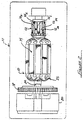
- the armature 10 for a brush commutated electric motor 11 having a plurality of coils wound in accordance with the teachings of the present invention.
- the armature 10 includes a commutator 12 which, merely by way of example, includes 24 independent commutator segments 12 1 - 12 24 .
- a lamination stack 14 is used to support a plurality of 24 coils 25 1 - 25 24 wound thereon.
- An armature shaft 22 extends through the lamination stack 14 and is fixedly coupled to a gear reduction assembly 20 and also to a fan 18. It will be appreciated, though, that the fan 18 and the gear reduction assembly 20 are optional and not essential to the armature 10 of the present invention, and shown merely because they are components that are often used in connection with an armature for an electric motor.
- the lamination stack 14 is illustrated without any coils wound thereon.
- the lamination stack 14 includes a plurality of radially projecting lamination posts or "teeth" 24. Twelve slots S 1 - S 12 are formed between the posts 24. It will be appreciated immediately, however, that while twelve such slots are illustrated, that a greater or lesser plurality could be employed. The overall number of slots depends on the number of commutator segments and will always be one-half the number of commutator segments used.
- Coil number 1 (25 1 ) has a first subcoil portion 1A and a second subcoil portion 1B formed in series with subcoil portion 1A.
- Subcoil portion 1A has one end thereof coupled to commutator segment number 12 1 and the end of second subcoil portion 1B is coupled to commutator segment number 12 2 .
- Subcoil portion 1A of coil 25 1 includes a first plurality of turns, for example seven turns, which are wound around slots S 12 and S 5 of the lamination stack 14.
- Subcoil portion 1B of coil 25 1 is then wound for a larger plurality of turns, in this example 17 turns, in slots S 1 and S 6 of the lamination stack 14.
- each subcoil portion can vary considerably, but in the preferred embodiment the number of turns between the subcoil portion 1B and portion 1A of coil 25 1 is such that one has preferably about three times as many winding turns as the other.
- the number of turns also alternates between the subcoils, as will be described further, such that adjacent coils will always have the two first subcoil portions with differing numbers of winding turns, and the two second subcoil portions with differing numbers of winding turns.
- Coil number 2 (25 2 ) also has a first subcoil portion 2A and a second subcoil 2B in series with one another.
- Subcoil portion 2A is wound in slots S 1 and S 6 with seventeen turns.
- Subcoil portion 2B is wound in series with portion 2A but around slots 5 2 and 5 7 of the lamination stack 14, and with seven winding turns.
- the end of subcoil portion 2A is coupled to commutator segment 12 2 while the end of subcoil portion 2B is coupled to commutator segment 12 3 .
- the first subcoil portion 2A of coil 25 2 overlaps the second subcoil portion 1B of coil 25 1 .
- Coil number 3 (25 3 ) includes a first subcoil portion 3A and a second subcoil portion in series with one another 3B.
- Subcoil portion 3A is attached to commutator segment number 12 3 and includes seven winding turns wound around slots S 1 and S 6 .
- Subcoil portion 3B is formed in series with subcoil portion 3A and includes seventeen turns wound in slots S 2 and S 7 , with the end thereof being coupled to commutator segment 12 4 .
- Coil 4 (25 4 ) also includes a first subcoil portion 4A and a second subcoil portion 4B in series with subcoil portion 4A.
- Subcoil portion 4A has its end coupled to commutator segment 12 4 and includes seventeen turns wound around slots S 2 and S 7 .
- Subcoil portion 4B includes seven turns wound around slots S 3 and S 8 , with the end thereof being coupled to commutator segment 12 5 .
- coil 25 4 partially overlaps coil 25 3 . In effect, one of the subcoil portions of each adjacent pair of coils 25 overlap with each other.
- coils 25 1 - 25 4 are repeated until all of the coils (in this example 12 coils) are wound onto the lamination stack 14.
- Each of the ends of the coils 25 1 - 25 12 are further secured to immediately adjacent pairs of commutator segments 12 1 - 12 24 .
- coil 25 5 has its ends secured to commutator segments 12 5 and 12 6 , coil 25 6 to segments 12 6 and 12 7 , and so forth.
- each coil 25 splits into first and second subcoil portions allows each first subcoil portion to shift its magnetic axis away (i.e., laterally), from the position it would have otherwise had in a traditional two-coil-per-slot approach. This is illustrated in Figure 5. All of the first subcoil portions shift their magnetic axes forward to produce a first coil commutation zone, as indicated by line 30, and all of the second subcoil portions shift their magnetic axes backward to produce a second coil commutation zone, as indicated by line 32, in reference to the armature's 10 rotational direction.
- Both of these commutation zones are now in a magnetic neutral zone between field coils 34.
- this winding pattern smoothes out the magnetic "unevenness" between adjacent coils, which is a drawback with traditional two-coil-per-slot winding patterns.
- This in connection with the shifting of the resultant magnetic axes of each coil, serves to significantly improve the commutation efficiency of the motor and to reduce the overall brush arcing.
- the winding pattern employed on the armature 10 of the present invention also serves to significantly reduce the cost of constructing the armature by eliminating components that would otherwise be needed to sufficiently attenuate the EMI that results from traditional two-coil-per-slot winding patterns.
- inductive components are required to form a choke circuit associated with each armature brush.
- the apparatus and method of the present invention thus allows an armature to be formed which significantly reduces brush arcing, and therefore the EMI that is present with traditional two-coil-per-slot armature constructions for all brush commutated electric motors.
- the apparatus and method of the present invention further does not increase the complexity of the manufacturing process or require additional component parts that would otherwise increase the overall cost of construction of an armature.
Landscapes
- Engineering & Computer Science (AREA)
- Power Engineering (AREA)
- Dc Machiner (AREA)
- Windings For Motors And Generators (AREA)
Abstract
Description
Claims (15)
- An electric motor having an armature with a coil winding pattern for reducing brush arcing and electromagnetic interference, comprising:a lamination stack having a plurality of radially extending posts, said posts forming a plurality of slots therebetween, said slots being arranged in a circumferential pattern;a plurality of coils wound around said slots, with each said coil being divided into first and second subcoil portions, with said first subcoil portion having a first plurality of winding turns and said second subcoil portion having a second plurality of winding turns, and wherein said first and second subcoil portions are wound in different, circumferentially offset pairs of said slots and coupled to first and second commutator segments of a commutator; andwherein said coils are wound such that adjacent pairs of said coils are wound in an overlapping fashion, with the second subcoil portion of a first coil of each said coil pair wound in the same pair of said slots as the first subcoil portion of a second coil of each said coil pair.
- The electric motor of claim 1, wherein one of said first and second subcoil portions of each coil has approximately three times the winding turns of the other.
- The electric motor of claim 2, wherein said second subcoil portion is wound around a pair of said slots which are shifted circumferentially by one said slot position from the second subcoil portion of its adjacent said coil.
- The electric motor of claim 1, wherein ends of said first and second subcoil portions are coupled to said commutator segments such that an end of each said second subcoil portion of each said coil is coupled to the same said commutator segment as the first subcoil portion of its adjacent said coil.
- A method for winding an armature of an electric motor, wherein the armature has a lamination stack forming a plurality of circumferentially arranged slots for winding thereon a plurality of coils, said method comprising:segmenting a first coil into first and second subcoil portions in series with one another;winding said first subcoil portion of said first coil around a first pair of spaced apart ones of said slots with a first plurality of winding turns;winding said second subcoil portion of said first coil around a second pair of spaced apart slots, which are circumferentially shifted from said first pair of slots, with a second plurality of winding turns;segmenting a second coil into first and second subcoil portions in series with one another;winding said first subcoil portion of said second coil around said second pair of spaced apart ones of said slots a number of turns in accordance with a third plurality of winding turns; andwinding said second subcoil portion of said second coil around a third pair of spaced apart slots shifted circumferentially from said second pair of spaced apart ones of said slots, with a fourth plurality of turns.
- The method of claim 5, wherein said second and third pluralities of winding turns are equal to one another.
- The method of claim 5, wherein said first and fourth pluralities of winding turns are equal to one another.
- The method of claim 5, wherein said first and second pluralities of winding turns differ such that one is always about three times the number of the other.
- The method of claim 5, further comprising the steps of:segmenting a third coil into first and second subcoil portions in series with one another;winding said first subcoil portion of said third coil around said second pair of spaced apart ones of said slots a number of turns in accordance with said first plurality of winding turns; andwinding said second subcoil portion of said third coil around said third pair of spaced apart ones of said slots a number of turns in accordance with said second plurality of winding turns.
- The method of claim 9, further comprising the steps of:segmenting a fourth coil into first and second subcoil portions in series with one another;winding said first subcoil portion of said fourth coil around said third pair of spaced apart slots with a number of turns in accordance with said second plurality of winding turns; andwinding said second subcoil portion of said fourth coil around a fourth pair of spaced apart ones of said slots shifted circumferentially by one slot position from said third pair of spaced apart ones of said slots, with a number of winding turns in accordance with said first plurality of winding turns.
- A method for winding an armature of an electric motor, wherein the armature has a lamination stack forming a plurality of circumferentially arranged slots for winding thereon a plurality of coils, said method comprising:segmenting a first coil into first and second subcoil portions in series with one another;winding said first subcoil portion of said first coil around a first pair of spaced apart ones of said slots with a first plurality of winding turns;winding said second subcoil portion of said first coil around a second pair of spaced apart slots which are circumferentially shifted from said first pair of slots, with a second plurality of winding turns;segmenting a second coil into first and second subcoil portions in series with one another;winding said first subcoil portion of said second coil around said second pair of spaced apart ones of said slots a number of turns in accordance with said second plurality of winding turns;winding said second subcoil portion of said second coil around a third pair of spaced apart slots shifted circumferentially from said second pair of spaced apart ones of said slots, with a number of turns in accordance with said first plurality of winding turns;segmenting a third coil into first and second subcoil portions in series with one another;winding said first subcoil portion of said third coil around said second pair of spaced apart ones of said slots a number of turns in accordance with said first plurality of winding turns;winding said second subcoil portion of said third coil around said third pair of spaced apart ones of said slots a number of turns in accordance with said second plurality of winding turns;segmenting a fourth coil into first and second subcoil portions in series with one another;winding said first subcoil portion of said fourth coil around said third pair of spaced apart slots with a number of turns in accordance with said second plurality of winding turns; andwinding said second subcoil portion of said fourth coil around a fourth pair of spaced apart ones of said slots shifted circumferentially by one slot position from said third pair of spaced apart ones of said slots, with a number of winding turns in accordance with said first plurality of winding turns.
- The method of claim 11, further comprising the steps of:securing ends of said first coil to adjacent first and second commutator segments of a commutator; andsecuring a first end of said second coil to said second commutator segment and a second end of said second coil to a third commutator segment of said commutator, with the third commutator segment being disposed immediately adjacent said second commutator segment.
- The method of claim 12, further comprising the steps of:
securing a first end of said third coil to said third commutator segment and a second end of said third coil to a fourth commutator segment, the fourth commutator segment being disposed immediately adjacent said third commutator segment. - The method of claim 13, further comprising the steps of:
securing a first end of said fourth coil to said fourth commutator segment and securing a second end of said fourth coil to a fifth commutator segment disposed immediately adjacent said fourth commutator segment. - The method of claim 11, further comprising the step of selecting said first and second pluralities of winding turns such that one includes approximately three times the turns of the other.
Priority Applications (1)
| Application Number | Priority Date | Filing Date | Title |
|---|---|---|---|
| EP07121402A EP1890372A2 (en) | 2000-06-14 | 2000-10-06 | Motor Armature having Distributed Windings for Reducing Arcing |
Applications Claiming Priority (2)
| Application Number | Priority Date | Filing Date | Title |
|---|---|---|---|
| US09/594,357 US6566782B1 (en) | 2000-06-14 | 2000-06-14 | Motor armature having distributed windings for reducing arcing |
| US594357 | 2000-06-14 |
Related Child Applications (1)
| Application Number | Title | Priority Date | Filing Date |
|---|---|---|---|
| EP07121402A Division EP1890372A2 (en) | 2000-06-14 | 2000-10-06 | Motor Armature having Distributed Windings for Reducing Arcing |
Publications (3)
| Publication Number | Publication Date |
|---|---|
| EP1164685A2 true EP1164685A2 (en) | 2001-12-19 |
| EP1164685A3 EP1164685A3 (en) | 2004-02-04 |
| EP1164685B1 EP1164685B1 (en) | 2008-05-28 |
Family
ID=24378557
Family Applications (2)
| Application Number | Title | Priority Date | Filing Date |
|---|---|---|---|
| EP07121402A Withdrawn EP1890372A2 (en) | 2000-06-14 | 2000-10-06 | Motor Armature having Distributed Windings for Reducing Arcing |
| EP00308848A Expired - Lifetime EP1164685B1 (en) | 2000-06-14 | 2000-10-06 | Motor armature having distributed windings for reducing arcing |
Family Applications Before (1)
| Application Number | Title | Priority Date | Filing Date |
|---|---|---|---|
| EP07121402A Withdrawn EP1890372A2 (en) | 2000-06-14 | 2000-10-06 | Motor Armature having Distributed Windings for Reducing Arcing |
Country Status (6)
| Country | Link |
|---|---|
| US (5) | US6566782B1 (en) |
| EP (2) | EP1890372A2 (en) |
| CN (1) | CN1179465C (en) |
| AT (1) | ATE397313T1 (en) |
| DE (1) | DE60039040D1 (en) |
| TW (1) | TW490914B (en) |
Cited By (7)
| Publication number | Priority date | Publication date | Assignee | Title |
|---|---|---|---|---|
| US6930429B2 (en) * | 2000-06-14 | 2005-08-16 | Black & Decker Inc. | Motor armature having distributed windings for reducing arcing |
| WO2005076442A1 (en) * | 2004-02-10 | 2005-08-18 | Mitsuba Corporation | Electric motor |
| EP1650853A1 (en) * | 2004-10-21 | 2006-04-26 | Makita Corporation | Winding scheme for a power tool motor |
| WO2007104589A1 (en) * | 2006-03-14 | 2007-09-20 | Robert Bosch Gmbh | Electrical machine |
| EP2736155A1 (en) * | 2007-10-08 | 2014-05-28 | Johnson Electric S.A. | Electric motor |
| EP1820249A4 (en) * | 2004-09-08 | 2016-09-14 | Black & Decker Inc | ENGINE ARMATURE HAVING DISTRIBUTED WINDINGS TO REDUCE ARC |
| FR3090237A1 (en) * | 2018-12-14 | 2020-06-19 | Valeo Equipements Electriques Moteur | Low-wear brush starter comprising a nested winding armature with sections distributed over several pairs of notches |
Families Citing this family (16)
| Publication number | Priority date | Publication date | Assignee | Title |
|---|---|---|---|---|
| DE112004001908T5 (en) * | 2003-10-08 | 2006-08-17 | Mitsuba Corp., Kiryu | Anchor of a rotating electrical machine and its manufacturing process |
| BRPI0515086B1 (en) * | 2004-10-22 | 2016-11-22 | Mitsuba Corp | method to produce an armature of a rotary electric machine |
| EP1815581A1 (en) * | 2004-11-26 | 2007-08-08 | Matsushita Electric Industrial Co., Ltd. | Commutator motor and method of manufacturing the same |
| DE102005035411A1 (en) * | 2005-03-31 | 2006-11-09 | Robert Bosch Gmbh | Electric machine |
| JP5097555B2 (en) * | 2005-11-22 | 2012-12-12 | 株式会社ミツバ | Armature in rotating electrical machine and method for manufacturing the same |
| SI2002527T1 (en) * | 2006-04-06 | 2012-12-31 | Metabowerke Gmbh | Rotor for a forced-air-cooled electric motor |
| JP5047717B2 (en) * | 2007-07-24 | 2012-10-10 | 株式会社マキタ | Electric motor |
| DE102008000614A1 (en) * | 2008-03-12 | 2009-09-17 | Robert Bosch Gmbh | Electric motor, motor system and method for determining an absolute angular position of a rotor of an electric motor |
| CN101958625B (en) * | 2009-07-16 | 2014-03-12 | 德昌电机(深圳)有限公司 | Brush motor |
| CN101958624B (en) * | 2009-07-20 | 2013-12-11 | 德昌电机(深圳)有限公司 | Motor |
| CN102624168B (en) * | 2012-03-21 | 2014-05-07 | 常州轻工职业技术学院 | Winding method of rotor coil of motor |
| US9425663B2 (en) | 2012-08-17 | 2016-08-23 | Black & Decker Inc. | Distributed winding arrangement for an electric motor |
| US9214837B2 (en) | 2013-12-13 | 2015-12-15 | Arm Limited | Electric motor with plural stator components |
| KR102547571B1 (en) * | 2018-07-26 | 2023-06-26 | 엘지이노텍 주식회사 | Motor |
| JP7314845B2 (en) * | 2020-03-24 | 2023-07-26 | 株式会社デンソー | motor |
| CN117639414B (en) * | 2024-01-26 | 2024-04-05 | 深圳市佰伦仕机电设备有限公司 | Automobile motor coil winding machine |
Family Cites Families (32)
| Publication number | Priority date | Publication date | Assignee | Title |
|---|---|---|---|---|
| DE25452C (en) | A. WlLK in Darmstadt | Device and circuit for feeding induction spirals with the current of dynamo-electric machines | ||
| US3126618A (en) * | 1964-03-31 | Method of manufacturing armatures | ||
| US841545A (en) * | 1906-06-29 | 1907-01-15 | Gen Electric | Dynamo-electric machine. |
| US1742112A (en) | 1927-03-17 | 1929-12-31 | Gen Electric | Dynamo-electric-machine armature |
| US2103166A (en) * | 1936-12-11 | 1937-12-21 | Gen Electric | Commutating type armature |
| US2272749A (en) | 1939-05-22 | 1942-02-10 | Gen Electric | Dynamoelectric machine |
| US2272479A (en) * | 1940-07-30 | 1942-02-10 | Pru Les Co Art Metal Co Inc | Picture frame or the like |
| US2529526A (en) * | 1948-07-28 | 1950-11-14 | Vickers Inc | Alternating current commutator machine |
| US2598464A (en) | 1951-05-10 | 1952-05-27 | Jeanne M Thomas | Dynamoelectric machine |
| US2921207A (en) | 1955-06-29 | 1960-01-12 | Fletcher Helen Gordon | Dynamo electric machines |
| US3239703A (en) * | 1963-03-18 | 1966-03-08 | Bosch Arma Corp | Armature apparatus for motors and method for making the same |
| US3631278A (en) | 1970-04-20 | 1971-12-28 | Gen Electric | Form-wound dynamoelectric machine with reduced coil distortion |
| DD109482A1 (en) | 1974-01-15 | 1974-11-05 | ||
| DE2744472C2 (en) | 1977-10-03 | 1983-11-03 | Siemens AG, 1000 Berlin und 8000 München | Electric two-motor drive |
| US4270065A (en) | 1979-03-19 | 1981-05-26 | Eltra Corporation | Four pole wave wound direct current machine with multi-turn armature coils |
| US4329610A (en) * | 1980-04-14 | 1982-05-11 | Black & Decker Inc. | Armature winding pattern for an electric motor |
| US4341971A (en) * | 1980-11-18 | 1982-07-27 | Hitachi, Ltd. | Armature of electric rotating machine |
| US4417388A (en) | 1980-11-28 | 1983-11-29 | Allied Corporation | Method of making a multiple open turn lap wound dynamoelectric machine |
| US4437029A (en) | 1981-10-16 | 1984-03-13 | Itsuki Ban | Direct current motor |
| US4447751A (en) | 1981-11-12 | 1984-05-08 | Itsuki Ban | Direct current motor |
| JPS58201568A (en) | 1982-05-20 | 1983-11-24 | Mitsubishi Electric Corp | Starting method for starter motor |
| US4583016A (en) | 1983-06-28 | 1986-04-15 | Itsuki Ban | Direct current motor |
| JPS6198379U (en) | 1984-11-30 | 1986-06-24 | ||
| DE3712652A1 (en) | 1986-05-03 | 1987-11-05 | Hans Hermann Rottmerhusen | Armature winding for commutator motors and generators having a plurality of pole pairs |
| CN86203906U (en) | 1986-05-30 | 1987-02-18 | 长沙电机厂 | Triphase variable pole multi-speed electric motor |
| CN2054227U (en) | 1989-08-11 | 1990-03-07 | 淄博电机二厂 | Synchronous generator with low harmonic winding |
| NL8902180A (en) | 1989-08-29 | 1991-03-18 | Philips Nv | METHOD FOR DEVELOPING AN ANCHOR BODY FROM AN ANCHOR AND ELECTRICAL MACHINE EQUIPPED WITH AN ANCHOR MADE ACCORDING TO THE METHOD |
| DE9003164U1 (en) | 1990-03-17 | 1991-07-18 | Robert Bosch Gmbh, 7000 Stuttgart | Armature for a small electrical machine |
| US5231324A (en) | 1990-07-19 | 1993-07-27 | Kabushiki Kaisha Toshiba | Three-phase armature winding |
| DE19705161C1 (en) | 1997-02-11 | 1998-01-02 | Hans Hermann Rottmerhusen | Armature winding of brakable commutator motor e.g. for electric power tools, such as circular saws |
| DE19818104C1 (en) | 1998-04-23 | 1999-06-24 | Hans Hermann Rottmerhusen | Armature winding for electric appliance or power handtool motor |
| US6566782B1 (en) * | 2000-06-14 | 2003-05-20 | Black & Decker Inc. | Motor armature having distributed windings for reducing arcing |
-
2000
- 2000-06-14 US US09/594,357 patent/US6566782B1/en not_active Expired - Fee Related
- 2000-10-06 EP EP07121402A patent/EP1890372A2/en not_active Withdrawn
- 2000-10-06 AT AT00308848T patent/ATE397313T1/en not_active IP Right Cessation
- 2000-10-06 DE DE60039040T patent/DE60039040D1/en not_active Expired - Lifetime
- 2000-10-06 EP EP00308848A patent/EP1164685B1/en not_active Expired - Lifetime
- 2000-10-13 TW TW089121447A patent/TW490914B/en not_active IP Right Cessation
- 2000-11-06 CN CNB001339877A patent/CN1179465C/en not_active Expired - Fee Related
-
2003
- 2003-04-01 US US10/404,857 patent/US7051420B2/en not_active Expired - Fee Related
- 2003-07-03 US US10/613,187 patent/US6930429B2/en not_active Expired - Fee Related
- 2003-07-03 US US10/613,645 patent/US7000307B2/en not_active Expired - Fee Related
-
2004
- 2004-09-20 US US10/944,958 patent/US7155811B2/en not_active Expired - Fee Related
Cited By (8)
| Publication number | Priority date | Publication date | Assignee | Title |
|---|---|---|---|---|
| US6930429B2 (en) * | 2000-06-14 | 2005-08-16 | Black & Decker Inc. | Motor armature having distributed windings for reducing arcing |
| WO2005076442A1 (en) * | 2004-02-10 | 2005-08-18 | Mitsuba Corporation | Electric motor |
| EP1820249A4 (en) * | 2004-09-08 | 2016-09-14 | Black & Decker Inc | ENGINE ARMATURE HAVING DISTRIBUTED WINDINGS TO REDUCE ARC |
| EP1650853A1 (en) * | 2004-10-21 | 2006-04-26 | Makita Corporation | Winding scheme for a power tool motor |
| US7388312B2 (en) | 2004-10-21 | 2008-06-17 | Makita Corporation | Power tool |
| WO2007104589A1 (en) * | 2006-03-14 | 2007-09-20 | Robert Bosch Gmbh | Electrical machine |
| EP2736155A1 (en) * | 2007-10-08 | 2014-05-28 | Johnson Electric S.A. | Electric motor |
| FR3090237A1 (en) * | 2018-12-14 | 2020-06-19 | Valeo Equipements Electriques Moteur | Low-wear brush starter comprising a nested winding armature with sections distributed over several pairs of notches |
Also Published As
| Publication number | Publication date |
|---|---|
| US20040020028A1 (en) | 2004-02-05 |
| US20030159271A1 (en) | 2003-08-28 |
| ATE397313T1 (en) | 2008-06-15 |
| CN1179465C (en) | 2004-12-08 |
| DE60039040D1 (en) | 2008-07-10 |
| CN1329384A (en) | 2002-01-02 |
| US7000307B2 (en) | 2006-02-21 |
| US7155811B2 (en) | 2007-01-02 |
| US20040017124A1 (en) | 2004-01-29 |
| EP1890372A2 (en) | 2008-02-20 |
| US20050034293A1 (en) | 2005-02-17 |
| US7051420B2 (en) | 2006-05-30 |
| US6930429B2 (en) | 2005-08-16 |
| US6566782B1 (en) | 2003-05-20 |
| EP1164685A3 (en) | 2004-02-04 |
| TW490914B (en) | 2002-06-11 |
| EP1164685B1 (en) | 2008-05-28 |
Similar Documents
| Publication | Publication Date | Title |
|---|---|---|
| US6566782B1 (en) | Motor armature having distributed windings for reducing arcing | |
| US20080016673A1 (en) | Motor armature having distributed windings for reducing arcing | |
| EP2483991B1 (en) | Brushless synchronous motor | |
| CN1902807B (en) | Motor with commutator rotor | |
| US7432626B2 (en) | Dynamoelectric machine having reduced magnetic noise and method | |
| JP2010500854A (en) | Electric equipment having a single-tooth mover winding | |
| EP1306963A1 (en) | Permanent magnet type rotary electric device | |
| JP4057266B2 (en) | Electric motor and winding method thereof | |
| CN114552836A (en) | Rotating electrical machine | |
| USRE48399E1 (en) | Distributed winding arrangement for an electric motor | |
| JP3233945B2 (en) | Claw type magnetic pole machine | |
| US12580431B2 (en) | Stator for an electric machine and electric machine for driving a vehicle | |
| US8191229B2 (en) | Rotor for a rotary electrical machine comprising grooves for magnets | |
| US20240048006A1 (en) | Stator for an electric machine, electric machine for driving a vehicle, and vehicle | |
| JP2006081262A (en) | Armature of rotating electric machine and its manufacturing method | |
| DE202016008461U1 (en) | Stator of an electric motor and electric motor | |
| US20190260242A1 (en) | Rotary electric machine | |
| JP2026079580A (en) | Motors, robots equipped with motors |
Legal Events
| Date | Code | Title | Description |
|---|---|---|---|
| PUAI | Public reference made under article 153(3) epc to a published international application that has entered the european phase |
Free format text: ORIGINAL CODE: 0009012 |
|
| AK | Designated contracting states |
Kind code of ref document: A2 Designated state(s): AT BE CH CY DE DK ES FI FR GB GR IE IT LI LU MC NL PT SE |
|
| AX | Request for extension of the european patent |
Free format text: AL;LT;LV;MK;RO;SI |
|
| PUAL | Search report despatched |
Free format text: ORIGINAL CODE: 0009013 |
|
| AK | Designated contracting states |
Kind code of ref document: A3 Designated state(s): AT BE CH CY DE DK ES FI FR GB GR IE IT LI LU MC NL PT SE |
|
| AX | Request for extension of the european patent |
Extension state: AL LT LV MK RO SI |
|
| RIC1 | Information provided on ipc code assigned before grant |
Ipc: 7H 02K 23/30 B Ipc: 7H 02K 3/28 A |
|
| 17P | Request for examination filed |
Effective date: 20040503 |
|
| 17Q | First examination report despatched |
Effective date: 20040706 |
|
| AKX | Designation fees paid |
Designated state(s): AT BE CH CY DE DK ES FI FR GB GR IE IT LI LU MC NL PT SE |
|
| GRAP | Despatch of communication of intention to grant a patent |
Free format text: ORIGINAL CODE: EPIDOSNIGR1 |
|
| GRAS | Grant fee paid |
Free format text: ORIGINAL CODE: EPIDOSNIGR3 |
|
| GRAA | (expected) grant |
Free format text: ORIGINAL CODE: 0009210 |
|
| AK | Designated contracting states |
Kind code of ref document: B1 Designated state(s): AT BE CH CY DE DK ES FI FR GB GR IE IT LI LU MC NL PT SE |
|
| REG | Reference to a national code |
Ref country code: GB Ref legal event code: FG4D |
|
| REG | Reference to a national code |
Ref country code: CH Ref legal event code: EP |
|
| REF | Corresponds to: |
Ref document number: 60039040 Country of ref document: DE Date of ref document: 20080710 Kind code of ref document: P |
|
| REG | Reference to a national code |
Ref country code: IE Ref legal event code: FG4D |
|
| REG | Reference to a national code |
Ref country code: SE Ref legal event code: TRGR |
|
| PG25 | Lapsed in a contracting state [announced via postgrant information from national office to epo] |
Ref country code: FI Free format text: LAPSE BECAUSE OF FAILURE TO SUBMIT A TRANSLATION OF THE DESCRIPTION OR TO PAY THE FEE WITHIN THE PRESCRIBED TIME-LIMIT Effective date: 20080528 Ref country code: ES Free format text: LAPSE BECAUSE OF FAILURE TO SUBMIT A TRANSLATION OF THE DESCRIPTION OR TO PAY THE FEE WITHIN THE PRESCRIBED TIME-LIMIT Effective date: 20080908 |
|
| PG25 | Lapsed in a contracting state [announced via postgrant information from national office to epo] |
Ref country code: NL Free format text: LAPSE BECAUSE OF FAILURE TO SUBMIT A TRANSLATION OF THE DESCRIPTION OR TO PAY THE FEE WITHIN THE PRESCRIBED TIME-LIMIT Effective date: 20080528 Ref country code: AT Free format text: LAPSE BECAUSE OF FAILURE TO SUBMIT A TRANSLATION OF THE DESCRIPTION OR TO PAY THE FEE WITHIN THE PRESCRIBED TIME-LIMIT Effective date: 20080528 |
|
| NLV1 | Nl: lapsed or annulled due to failure to fulfill the requirements of art. 29p and 29m of the patents act | ||
| PG25 | Lapsed in a contracting state [announced via postgrant information from national office to epo] |
Ref country code: PT Free format text: LAPSE BECAUSE OF FAILURE TO SUBMIT A TRANSLATION OF THE DESCRIPTION OR TO PAY THE FEE WITHIN THE PRESCRIBED TIME-LIMIT Effective date: 20081028 Ref country code: DK Free format text: LAPSE BECAUSE OF FAILURE TO SUBMIT A TRANSLATION OF THE DESCRIPTION OR TO PAY THE FEE WITHIN THE PRESCRIBED TIME-LIMIT Effective date: 20080528 |
|
| PG25 | Lapsed in a contracting state [announced via postgrant information from national office to epo] |
Ref country code: BE Free format text: LAPSE BECAUSE OF FAILURE TO SUBMIT A TRANSLATION OF THE DESCRIPTION OR TO PAY THE FEE WITHIN THE PRESCRIBED TIME-LIMIT Effective date: 20080528 |
|
| PLBE | No opposition filed within time limit |
Free format text: ORIGINAL CODE: 0009261 |
|
| STAA | Information on the status of an ep patent application or granted ep patent |
Free format text: STATUS: NO OPPOSITION FILED WITHIN TIME LIMIT |
|
| 26N | No opposition filed |
Effective date: 20090303 |
|
| PG25 | Lapsed in a contracting state [announced via postgrant information from national office to epo] |
Ref country code: MC Free format text: LAPSE BECAUSE OF NON-PAYMENT OF DUE FEES Effective date: 20081031 |
|
| REG | Reference to a national code |
Ref country code: CH Ref legal event code: PL |
|
| REG | Reference to a national code |
Ref country code: IE Ref legal event code: MM4A |
|
| PG25 | Lapsed in a contracting state [announced via postgrant information from national office to epo] |
Ref country code: LI Free format text: LAPSE BECAUSE OF NON-PAYMENT OF DUE FEES Effective date: 20081031 Ref country code: CH Free format text: LAPSE BECAUSE OF NON-PAYMENT OF DUE FEES Effective date: 20081031 Ref country code: IE Free format text: LAPSE BECAUSE OF NON-PAYMENT OF DUE FEES Effective date: 20081006 |
|
| PG25 | Lapsed in a contracting state [announced via postgrant information from national office to epo] |
Ref country code: LU Free format text: LAPSE BECAUSE OF NON-PAYMENT OF DUE FEES Effective date: 20081006 Ref country code: CY Free format text: LAPSE BECAUSE OF FAILURE TO SUBMIT A TRANSLATION OF THE DESCRIPTION OR TO PAY THE FEE WITHIN THE PRESCRIBED TIME-LIMIT Effective date: 20080528 |
|
| PG25 | Lapsed in a contracting state [announced via postgrant information from national office to epo] |
Ref country code: GR Free format text: LAPSE BECAUSE OF FAILURE TO SUBMIT A TRANSLATION OF THE DESCRIPTION OR TO PAY THE FEE WITHIN THE PRESCRIBED TIME-LIMIT Effective date: 20080829 |
|
| PGFP | Annual fee paid to national office [announced via postgrant information from national office to epo] |
Ref country code: SE Payment date: 20131029 Year of fee payment: 14 Ref country code: DE Payment date: 20131029 Year of fee payment: 14 Ref country code: GB Payment date: 20131028 Year of fee payment: 14 Ref country code: FR Payment date: 20131017 Year of fee payment: 14 |
|
| PGFP | Annual fee paid to national office [announced via postgrant information from national office to epo] |
Ref country code: IT Payment date: 20131024 Year of fee payment: 14 |
|
| REG | Reference to a national code |
Ref country code: DE Ref legal event code: R119 Ref document number: 60039040 Country of ref document: DE |
|
| REG | Reference to a national code |
Ref country code: SE Ref legal event code: EUG |
|
| GBPC | Gb: european patent ceased through non-payment of renewal fee |
Effective date: 20141006 |
|
| PG25 | Lapsed in a contracting state [announced via postgrant information from national office to epo] |
Ref country code: GB Free format text: LAPSE BECAUSE OF NON-PAYMENT OF DUE FEES Effective date: 20141006 Ref country code: SE Free format text: LAPSE BECAUSE OF NON-PAYMENT OF DUE FEES Effective date: 20141007 Ref country code: DE Free format text: LAPSE BECAUSE OF NON-PAYMENT OF DUE FEES Effective date: 20150501 |
|
| REG | Reference to a national code |
Ref country code: FR Ref legal event code: ST Effective date: 20150630 |
|
| PG25 | Lapsed in a contracting state [announced via postgrant information from national office to epo] |
Ref country code: FR Free format text: LAPSE BECAUSE OF NON-PAYMENT OF DUE FEES Effective date: 20141031 Ref country code: IT Free format text: LAPSE BECAUSE OF NON-PAYMENT OF DUE FEES Effective date: 20141006 |