EP1164647A2 - Handle for electric accumulator battery - Google Patents
Handle for electric accumulator battery Download PDFInfo
- Publication number
- EP1164647A2 EP1164647A2 EP01500131A EP01500131A EP1164647A2 EP 1164647 A2 EP1164647 A2 EP 1164647A2 EP 01500131 A EP01500131 A EP 01500131A EP 01500131 A EP01500131 A EP 01500131A EP 1164647 A2 EP1164647 A2 EP 1164647A2
- Authority
- EP
- European Patent Office
- Prior art keywords
- handle
- battery
- cover
- oval
- nipples
- Prior art date
- Legal status (The legal status is an assumption and is not a legal conclusion. Google has not performed a legal analysis and makes no representation as to the accuracy of the status listed.)
- Withdrawn
Links
Images

Classifications
-
- H—ELECTRICITY
- H01—ELECTRIC ELEMENTS
- H01M—PROCESSES OR MEANS, e.g. BATTERIES, FOR THE DIRECT CONVERSION OF CHEMICAL ENERGY INTO ELECTRICAL ENERGY
- H01M50/00—Constructional details or processes of manufacture of the non-active parts of electrochemical cells other than fuel cells, e.g. hybrid cells
- H01M50/20—Mountings; Secondary casings or frames; Racks, modules or packs; Suspension devices; Shock absorbers; Transport or carrying devices; Holders
- H01M50/256—Carrying devices, e.g. belts
-
- Y—GENERAL TAGGING OF NEW TECHNOLOGICAL DEVELOPMENTS; GENERAL TAGGING OF CROSS-SECTIONAL TECHNOLOGIES SPANNING OVER SEVERAL SECTIONS OF THE IPC; TECHNICAL SUBJECTS COVERED BY FORMER USPC CROSS-REFERENCE ART COLLECTIONS [XRACs] AND DIGESTS
- Y02—TECHNOLOGIES OR APPLICATIONS FOR MITIGATION OR ADAPTATION AGAINST CLIMATE CHANGE
- Y02E—REDUCTION OF GREENHOUSE GAS [GHG] EMISSIONS, RELATED TO ENERGY GENERATION, TRANSMISSION OR DISTRIBUTION
- Y02E60/00—Enabling technologies; Technologies with a potential or indirect contribution to GHG emissions mitigation
- Y02E60/10—Energy storage using batteries
-
- Y—GENERAL TAGGING OF NEW TECHNOLOGICAL DEVELOPMENTS; GENERAL TAGGING OF CROSS-SECTIONAL TECHNOLOGIES SPANNING OVER SEVERAL SECTIONS OF THE IPC; TECHNICAL SUBJECTS COVERED BY FORMER USPC CROSS-REFERENCE ART COLLECTIONS [XRACs] AND DIGESTS
- Y10—TECHNICAL SUBJECTS COVERED BY FORMER USPC
- Y10S—TECHNICAL SUBJECTS COVERED BY FORMER USPC CROSS-REFERENCE ART COLLECTIONS [XRACs] AND DIGESTS
- Y10S16/00—Miscellaneous hardware, e.g. bushing, carpet fastener, caster, door closer, panel hanger, attachable or adjunct handle, hinge, window sash balance
- Y10S16/15—Battery handles
-
- Y—GENERAL TAGGING OF NEW TECHNOLOGICAL DEVELOPMENTS; GENERAL TAGGING OF CROSS-SECTIONAL TECHNOLOGIES SPANNING OVER SEVERAL SECTIONS OF THE IPC; TECHNICAL SUBJECTS COVERED BY FORMER USPC CROSS-REFERENCE ART COLLECTIONS [XRACs] AND DIGESTS
- Y10—TECHNICAL SUBJECTS COVERED BY FORMER USPC
- Y10S—TECHNICAL SUBJECTS COVERED BY FORMER USPC CROSS-REFERENCE ART COLLECTIONS [XRACs] AND DIGESTS
- Y10S294/00—Handling: hand and hoist-line implements
- Y10S294/903—Battery carrier
Definitions
- the object of the present utility model is a handle for the transport and manipulation of electric accumulator batteries, preferably for batteries of the type for starting motor cars.
- handles are already known for facilitating the transport and manipulation of batteries, of which almost all utilise flexible elements such as plastic straps or cords in order that, while permitting the hand-carrying of the battery, the mounting of the battery in the vehicle is not obstructed or even impeded; also known are some rigid handles with different systems of lowering and fastening and swivelling the handle mentioned, the majority of which must be removed from the battery when it is installed in the vehicle, in order to permit the assembly of the terminals with the pertinent clamps.
- the handle of the present invention is rigid, permitting the handling of the battery with complete ease and nevertheless presents no difficulty when mounting the battery, due to its special design.
- the handle of the present invention is characterised in that it has a double ladder configuration of two steps on each side, with two windows or openings of oval shape at the lower ends situated in such a manner that it permits their fitting on and rotation about each of the side pivots joined to the upper part of the cover and at the same time permits it to be lowered on to the upper face or cover of the battery.
- This handle is specially designed in order to permit easy mounting due to the fitting of the windows of the handle on the pivots of the cover and also to permit the batteries to be stacked in the warehouse.
- the top part of the double ladder which shall serve as the grip of the handle of the invention, is positioned between the battery connection terminals and precisely at the same height as the top part of the cover, projecting slightly over the top part of the lead terminals, in such a manner that the base is enlarged on which the batteries shall stand when stacked and therefore the risk of falling over is diminished, at the same time as the risk is minimised of breaks in or damage to the bottom or base of the batteries when stacked on top of each other, since the projecting parts which usually produce damage to the bottom of the batteries are the terminals themselves and these, when employing the design of the handle of the invention, are located at a lower level than the cover and the grip.
- the pivots around which the handle of the invention swivels, are situated on the two sides of the cover, the pivots are shaped like a mushroom, the outer part of which is oval in form and thicker than the inside which is circular in order to permit the handle to turn.
- the outermost and oval-shaped part of the pivots is dimensionally slightly less than the oval in the openings in the handle and the major axis of the oval of the pivots forms an angle of less than 90o, preferably 65o to the horizontal, in such a manner that it only permits the handle to be mounted when the latter is positioned forming that angle to the horizontal.
- the fitting of the handle on the pivots of the cover is carried out by means of a simple movement and with virtually minimum force.
- the handle accepts displacement and rotation with ease and with maximum guarantee of safety because the cover shall be unable to withdraw from its engagement whilst the handle is maintained upright forming an angle of 90o to the horizontal, which is the only position in which it is possible to transport the battery suspended from its handle.
- the handle can only be detached when it forms the same angle with the horizontal as that of the outermost part of the pivots and this is always much less than 90o, normally 65o and therefore during the transport of the batteries suspended from their handle, that is when the handle is raised, there is no risk of batteries falling as a result of aforesaid handle escaping from its engagement.
- the material employed to fabricate said handles can be of many types. Preferably, for practical and decorative reasons, the same material is employed as that used in the manufacture of the covers and of the pivots about which it has to work.
- the handle of the present invention includes three holes situated on the upper part and on each of the two sides that surround the terminal of each polarity. Into these holes are inserted the nipples which are included on the lower part of some special pieces that shall serve to cover the battery terminals; whilst the battery is in storage or is being transported to the vehicle in which it shall be mounted. These terminal cover-pieces with which the handle is provided shall serve to protect the terminals from any possible short circuit, as well as contribute to the better identification of the polarity of the battery, given that they are marked with the positive and negative signs.
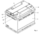
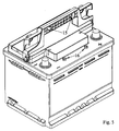
- This cover has a special design to permit the collocating of the handle 3 of the invention.
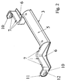
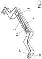
- said cover 2 is provided with two side pivots 4 around which shall swivel the handle 3, which as may be better appreciated in figures 2 and 3 takes the form of a double ladder with two steps on each side, the grip 5 constituting the central part, the span, which forms the first step of each side, strengthened with a bracket-shaped web 6, serving to house the terminals of the battery.
- the walls that form said span are provided on the upper part with holes 7 which cooperate with the nipples 8, present on each of the terminal cover-pieces 9 for the fastening of these to the handle, thereby preventing possible damage to the terminals during storage and transport of the battery, as well as the occurrence of short circuits.
- the two ends of the handle are formed by walls 10 with the extreme edge 11 rounded and strengthened and each provided with oval openings 12.
- Said oval openings 12 cooperate with the pivots 4 of the cover 2, for which purpose they have an outermost part 13 also oval but of smaller dimensions than those of the openings 12 of the handle and an inner cylindrical part 14 of length slightly greater than the thickness of the walls 10 of the handle and having a diameter less than the minor axis of the oval opening 12.
- the handle 3 in the region of the grip 5 is provided with cavities 15 which collaborate with the fixed nipples 16 provided on the cover 2 of the battery, as can be seen in figure 5, in order to prevent the handle being able to move and strike the cover with the vibration resulting from the motion of the vehicle.
Landscapes
- Chemical & Material Sciences (AREA)
- Chemical Kinetics & Catalysis (AREA)
- Electrochemistry (AREA)
- General Chemical & Material Sciences (AREA)
- Battery Mounting, Suspending (AREA)
- Sealing Battery Cases Or Jackets (AREA)
- Connection Of Batteries Or Terminals (AREA)
Abstract
Description
Claims (4)
- Handle for electric accumulator battery, of the type which is mounted rotationally on the battery in order to facilitate its transport, characterised in that it has the form of a double ladder, with two steps on each side, its end walls of a rounded and strengthened perimeter being each provided with oval openings which cooperate with two lateral nipples on the battery cover, which have an outermost portion oval in shape, of dimensions slightly less than those of the openings and an internal portion, of length slightly greater than the thickness of the said walls and having a diameter slightly less than the minor axis of the oval opening, each span of the first step serving to house the terminals corresponding to the battery.
- Handle for electric accumulator battery, in accordance with claim 1, characterised in that the major axis of the oval outermost portion of the nipples is appreciably horizontal and the major axis of the openings is also horizontal, when the handle is folded down.
- Handle for electric accumulator battery, in accordance with previous claims, characterised in that the upper part of the walls which form the span of the first step are provided with orifices which cooperate with nipples provided on terminal cover-pieces.
- Handle for electric accumulator battery, in accordance with previous claims, characterised in that the central part of the handle that constitutes the grip is provided with cavities which cooperate with nipples provided on the cover of the battery to prevent the movement of the handle.
Applications Claiming Priority (2)
| Application Number | Priority Date | Filing Date | Title |
|---|---|---|---|
| ES200001583U ES1046536Y (en) | 2000-06-13 | 2000-06-13 | HANDLE FOR BATTERY OF ELECTRIC ACCUMULATORS. |
| ES200001583 | 2000-06-13 |
Publications (2)
| Publication Number | Publication Date |
|---|---|
| EP1164647A2 true EP1164647A2 (en) | 2001-12-19 |
| EP1164647A3 EP1164647A3 (en) | 2005-04-13 |
Family
ID=8494018
Family Applications (1)
| Application Number | Title | Priority Date | Filing Date |
|---|---|---|---|
| EP01500131A Withdrawn EP1164647A3 (en) | 2000-06-13 | 2001-05-25 | Handle for electric accumulator battery |
Country Status (3)
| Country | Link |
|---|---|
| US (1) | US6499190B2 (en) |
| EP (1) | EP1164647A3 (en) |
| ES (1) | ES1046536Y (en) |
Cited By (3)
| Publication number | Priority date | Publication date | Assignee | Title |
|---|---|---|---|---|
| FR2957318A1 (en) * | 2010-03-15 | 2011-09-16 | Andre Luc | System for recharging and replacing oblige power batteries utilized to supply electric power to engine of car, has base plate firmly fixed at vehicle, and electric battery moving to position on base plate and spacers connection |
| EP2421066A1 (en) * | 2010-08-19 | 2012-02-22 | Alfa Kutu VE Plastik San. VE TIC., Ltd. | Accumulator cover with self locking handle mechanism |
| WO2022246289A3 (en) * | 2021-05-21 | 2023-02-23 | Cps Technology Holdings Llc | Battery connector and battery cover |
Families Citing this family (25)
| Publication number | Priority date | Publication date | Assignee | Title |
|---|---|---|---|---|
| USD517476S1 (en) * | 2004-09-10 | 2006-03-21 | Pabban Development Inc. | Battery pack for helmets |
| US20070123856A1 (en) * | 2005-10-27 | 2007-05-31 | Deffenbaugh Daren L | Trauma joint, external fixator and associated method |
| ES2316216B1 (en) * | 2006-02-07 | 2009-11-05 | Polylux, S.L. | COVER COVER, IN SPECIAL FOR SMALL POWER TRANSFORMERS. |
| US20080169676A1 (en) * | 2007-01-11 | 2008-07-17 | Textron Inc. | Battery Tray for a Golf Car |
| US7836556B1 (en) * | 2008-06-03 | 2010-11-23 | Medeiros Mark A | Motorcycle battery carrying apparatus |
| US8338710B2 (en) * | 2010-11-03 | 2012-12-25 | Ford Global Technologies, Llc | Short-preventing shield for wire harness terminals |
| WO2015019741A1 (en) * | 2013-08-07 | 2015-02-12 | 日産自動車株式会社 | Structure for mounting battery on vehicle |
| USD726649S1 (en) * | 2013-10-15 | 2015-04-14 | Lg Electronics Inc. | Portable battery for head mount display device |
| USD730279S1 (en) * | 2014-01-21 | 2015-05-26 | Limefuel, LLC | Battery for an electronic device |
| USD751983S1 (en) | 2014-09-22 | 2016-03-22 | Limefuel, LLC | Rechargeable battery device |
| USD751981S1 (en) | 2014-09-22 | 2016-03-22 | Limefuel, LLC | Rechargeable battery device |
| USD751982S1 (en) | 2014-09-22 | 2016-03-22 | Limefuel, LLC | Rechargeable battery device |
| USD752509S1 (en) | 2014-09-22 | 2016-03-29 | Limefuel, LLC | Rechargeable battery device |
| USD752510S1 (en) | 2014-09-22 | 2016-03-29 | Limefuel, LLC | Rechargeable battery device |
| USD751984S1 (en) | 2014-09-22 | 2016-03-22 | Limefuel, LLC | Rechargeable battery device |
| USD780112S1 (en) | 2015-02-18 | 2017-02-28 | Limefuel, LLC | Rechargeable battery device |
| USD788698S1 (en) | 2015-02-18 | 2017-06-06 | Limefuel, LLC | Rechargeable battery device |
| USD815032S1 (en) | 2015-02-20 | 2018-04-10 | Limefuel, LLC | Rechargeable battery device |
| USD904321S1 (en) * | 2019-06-24 | 2020-12-08 | Intel Corporation | Handle for a server fan module |
| JP7331747B2 (en) * | 2020-03-19 | 2023-08-23 | トヨタ自動車株式会社 | vehicle power unit |
| USD911933S1 (en) | 2020-07-10 | 2021-03-02 | Inventus Power, Inc. | Battery |
| USD910546S1 (en) | 2020-07-10 | 2021-02-16 | Inventus Power, Inc. | Battery |
| USD910548S1 (en) * | 2020-07-21 | 2021-02-16 | Inventus Power, Inc. | Battery |
| USD910547S1 (en) * | 2020-07-21 | 2021-02-16 | Inventus Power, Inc. | Battery |
| US12369524B2 (en) | 2021-12-09 | 2025-07-29 | Honda Motor Co., Ltd. | Battery system, power equipment apparatus having the same, and electric lawnmower |
Family Cites Families (14)
| Publication number | Priority date | Publication date | Assignee | Title |
|---|---|---|---|---|
| US897472A (en) * | 1907-07-19 | 1908-09-01 | Joseph Marx | Jar for storage batteries. |
| DE2305858A1 (en) * | 1973-02-02 | 1974-08-08 | Kadow & Riese Inh Ernst Lux In | PIPE BEND FOR PIPE MAIL SYSTEMS |
| US4029248A (en) * | 1975-05-27 | 1977-06-14 | Gould Inc. | Detachable battery carrying handle |
| US4673625A (en) * | 1986-08-04 | 1987-06-16 | General Motors Corporation | Battery and handle therefor |
| AT389596B (en) * | 1987-02-25 | 1989-12-27 | Semperit Ag | BATTERY COVER WITH HANDLES |
| US5232796A (en) * | 1991-09-19 | 1993-08-03 | Gnb Incorporated | Battery with multiple position handle |
| US5637420A (en) * | 1995-09-01 | 1997-06-10 | Globe-Union Inc. | Self-latching handle for storage batteries |
| US5624772A (en) * | 1995-11-17 | 1997-04-29 | General Motors Corporation | Battery handle |
| GB9606421D0 (en) * | 1996-03-27 | 1996-06-05 | Lucas Yuasa Batteries Ltd | Batteries |
| US6022638A (en) * | 1997-05-20 | 2000-02-08 | Gnb Technologies, Inc. | Lead-acid battery with handle |
| DE29720115U1 (en) * | 1997-11-13 | 1998-01-02 | Accumulatorenwerke Hoppecke Carl Zoellner & Sohn GmbH & Co. KG, 59929 Brilon | Handle system for accumulators |
| US6117588A (en) * | 1998-04-29 | 2000-09-12 | Gnb Technologies, Inc. | Detachable battery handle assembly |
| US6153331A (en) * | 1999-05-14 | 2000-11-28 | Delphi Technologies, Inc. | Battery handle holddown |
| DE20000776U1 (en) * | 2000-01-18 | 2000-06-21 | VB Autobatterie GmbH, 30419 Hannover | Accumulator battery, especially lead / acid battery, with measuring device for function control |
-
2000
- 2000-06-13 ES ES200001583U patent/ES1046536Y/en not_active Expired - Fee Related
-
2001
- 2001-05-25 EP EP01500131A patent/EP1164647A3/en not_active Withdrawn
- 2001-06-12 US US09/879,394 patent/US6499190B2/en not_active Expired - Fee Related
Cited By (3)
| Publication number | Priority date | Publication date | Assignee | Title |
|---|---|---|---|---|
| FR2957318A1 (en) * | 2010-03-15 | 2011-09-16 | Andre Luc | System for recharging and replacing oblige power batteries utilized to supply electric power to engine of car, has base plate firmly fixed at vehicle, and electric battery moving to position on base plate and spacers connection |
| EP2421066A1 (en) * | 2010-08-19 | 2012-02-22 | Alfa Kutu VE Plastik San. VE TIC., Ltd. | Accumulator cover with self locking handle mechanism |
| WO2022246289A3 (en) * | 2021-05-21 | 2023-02-23 | Cps Technology Holdings Llc | Battery connector and battery cover |
Also Published As
| Publication number | Publication date |
|---|---|
| ES1046536U (en) | 2001-01-01 |
| US6499190B2 (en) | 2002-12-31 |
| EP1164647A3 (en) | 2005-04-13 |
| ES1046536Y (en) | 2001-06-01 |
| US20020017008A1 (en) | 2002-02-14 |
Similar Documents
| Publication | Publication Date | Title |
|---|---|---|
| EP1164647A2 (en) | Handle for electric accumulator battery | |
| US5283137A (en) | Cover assembly for rechargeable battery | |
| US5637420A (en) | Self-latching handle for storage batteries | |
| JP3485719B2 (en) | Battery pack that can be installed without orientation | |
| CN116848053A (en) | Electric vehicle battery shipping container with battery retaining hooks | |
| JPH06156558A (en) | Trunk | |
| EP2131415A1 (en) | A battery with pair of handle assemblies | |
| US5323943A (en) | Lawn chair caddy apparatus | |
| JPH1040895A (en) | Battery handle | |
| JP3676225B2 (en) | Battery pack for electric vehicles | |
| KR101478701B1 (en) | Coupling Member Including Welding Connecting Portion and Coupling Recess Portion and Battery Module Assembly Employed with the Same | |
| EP0821420A1 (en) | Battery pack | |
| CN216488325U (en) | Novel lithium ion power battery box | |
| KR102741651B1 (en) | Safety Battery Cover | |
| JP3500887B2 (en) | Storage battery suspension structure | |
| JPH0897568A (en) | Dry battery housing structure | |
| JP2001307695A (en) | Battery pack | |
| KR20190049750A (en) | How to handle rechargeable battery modules and rechargeable battery modules | |
| CN216720110U (en) | Battery box | |
| CN215944266U (en) | Loader battery installation assembly and electric loader | |
| JP2563273Y2 (en) | Battery suspenders | |
| CN213083016U (en) | AGV automobile body anti-overturning device | |
| CN211544289U (en) | Storage box for storage battery | |
| JPH079808Y2 (en) | A carrier for multiple cans | |
| CN218145240U (en) | Goods elevator with safety protection mechanism |
Legal Events
| Date | Code | Title | Description |
|---|---|---|---|
| PUAI | Public reference made under article 153(3) epc to a published international application that has entered the european phase |
Free format text: ORIGINAL CODE: 0009012 |
|
| AK | Designated contracting states |
Kind code of ref document: A2 Designated state(s): AT BE CH CY DE DK ES FI FR GB GR IE IT LI LU MC NL PT SE TR |
|
| AX | Request for extension of the european patent |
Free format text: AL;LT;LV;MK;RO;SI |
|
| PUAL | Search report despatched |
Free format text: ORIGINAL CODE: 0009013 |
|
| AK | Designated contracting states |
Kind code of ref document: A3 Designated state(s): AT BE CH CY DE DK ES FI FR GB GR IE IT LI LU MC NL PT SE TR |
|
| AX | Request for extension of the european patent |
Extension state: AL LT LV MK RO SI |
|
| 17P | Request for examination filed |
Effective date: 20050526 |
|
| AKX | Designation fees paid |
Designated state(s): DE ES FR GB IT PT |
|
| 17Q | First examination report despatched |
Effective date: 20071025 |
|
| STAA | Information on the status of an ep patent application or granted ep patent |
Free format text: STATUS: THE APPLICATION IS DEEMED TO BE WITHDRAWN |
|
| 18D | Application deemed to be withdrawn |
Effective date: 20071101 |