EP1164448A2 - Control apparatus - Google Patents
Control apparatus Download PDFInfo
- Publication number
- EP1164448A2 EP1164448A2 EP01114340A EP01114340A EP1164448A2 EP 1164448 A2 EP1164448 A2 EP 1164448A2 EP 01114340 A EP01114340 A EP 01114340A EP 01114340 A EP01114340 A EP 01114340A EP 1164448 A2 EP1164448 A2 EP 1164448A2
- Authority
- EP
- European Patent Office
- Prior art keywords
- gain
- output
- controlled system
- deviation
- feedback
- Prior art date
- Legal status (The legal status is an assumption and is not a legal conclusion. Google has not performed a legal analysis and makes no representation as to the accuracy of the status listed.)
- Withdrawn
Links
Images


Classifications
-
- G—PHYSICS
- G05—CONTROLLING; REGULATING
- G05B—CONTROL OR REGULATING SYSTEMS IN GENERAL; FUNCTIONAL ELEMENTS OF SUCH SYSTEMS; MONITORING OR TESTING ARRANGEMENTS FOR SUCH SYSTEMS OR ELEMENTS
- G05B19/00—Programme-control systems
- G05B19/02—Programme-control systems electric
- G05B19/18—Numerical control [NC], i.e. automatically operating machines, in particular machine tools, e.g. in a manufacturing environment, so as to execute positioning, movement or co-ordinated operations by means of programme data in numerical form
- G05B19/19—Numerical control [NC], i.e. automatically operating machines, in particular machine tools, e.g. in a manufacturing environment, so as to execute positioning, movement or co-ordinated operations by means of programme data in numerical form characterised by positioning or contouring control systems, e.g. to control position from one programmed point to another or to control movement along a programmed continuous path
Definitions
- the present invention relates to a control apparatus applied to a speed control or a position control in an industrial robot, a numerical control (NC) machine, a head track seeking of a disk drive or the like.
- NC numerical control
- a servo mechanism using a servo actuator has been widely utilized in a position-to-position high speed positioning control or a high speed tracking control for an industrial robot, a NC machine and the like, and a head track seeking or the like for a hard disk drive or a floppy disk drive used in a data processing unit.
- a high speed response is one of very important conditions for such a control as a speed control, a positioning control or the like.
- the settling time becomes a minimum time, when a critical damping wherein a damping coefficient of a control system constructing a control apparatus becomes 1 is made under a condition that an overshoot does not occur. That is, in a conventional control system constructed by an inner loop for a negative feedback of an output and another inner loop for negative-feeding back the product of the differential value of the output and a gain, the settling time may be set to be minimum by setting the gain in the another inner value in a proper value. Namely, the response of the control system of the conventional control apparatus is expressed by the following differential equation (1).
- the damping coefficient ⁇ exceeds 1, the response becomes slower, so that the settling time is prolonged.
- the damping coefficient ⁇ becomes less than 1 the response becomes faster but vibrating even when an overshoot is allowed, so that much improvement can not be obtained.
- An object of the present invention is to provide a control apparatus which reduces the settling time largely without occurrence of an overshoot and which achieves a high speed response.
- a control apparatus which controls a controlled system with a transfer function regarded as a secondary delay system.
- the control apparatus comprises an outer loop for a negative feedback of an output x of the controlled system in order to obtain an error e between the output x and a desired value r ; a first inner loop for a negative feedback of a signal k1 ⁇ (dx/dt) obtained by multiplying a differential value (dx/dt) of the output x of the controlled system by a gain k1 to the deviation e ; and a second inner loop for a positive feedback of a signal of k2(dx/dt) ⁇
- the gains k1 and k2 are set so as to meet a predetermined conditional expression of damping coefficients of a control system which are zero and positive, the settling time can be reduced largely and a high speed response can be achieved without occurrence of an overshoot even in a control system having a controlled system with a transfer function regarded as an secondary delay.
- FIG. 1 shows a control apparatus according to the embodiment of the present invention and applied to a speed control system having the controlled system regarded as a second order system.
- a servo mechanism using a servo actuator a speed control system having an inertia moment or a mass wherein a torque or a thrust generator is approximated with the first order lag element, a position control system wherein a speed controller is approximated with the first order element, or the like is exemplified as a controlled system regarded as the second order system.
- This control apparatus comprises a multi-closed loop control system.
- the control apparatus comprises an outer loop 2, an inner loop 4 and a nonlinear inner feedback loop 10.
- the outer loop 2 executes a negative feedback of an output from a controlled system 1, and includes a deviation computing unit 3 which computes the deviation between a desired value r and a controlled variable, namely the output x which is the signal of the outer loop 2.
- the inner loop 4 executes a negative feedback of the product between a differential value of the controlled variable, namely the speed x and a gain k1, that is, a compensation signal to a transient change.
- a compensation unit 5 performs such a processing that the deviation from the deviation computing unit 3 is cancelled by the compensation signal from the inner loop 4, and a nonlinear inner feedback loop 10.
- the inner loop 4 comprises a computing unit 6 having a laplace operator s which takes out the differentiated output of the controlled variable or the output x of the controlled system 1 and a gain multiplier 7 which multiplies a proper gain k1 to the differentiated output from the computing unit 6 for a feedback.
- the inner loop 4 generates the compensation signal for the transient change of the controlled variable or the output x .
- J in the transfer function of the controlled system 1 is an inertial moment
- T is a time constant
- s is a laplace operator unit.
- Such a control apparatus can control the output of the controlled system 1 to a transient change by setting the gain k1 multiplied to the differentiation of the controlled variable, namely output x of the controlled system 1 properly using the inner loop 4 to conduct compensation through a feedback.
- the nonlinear inner feedback loop 10 forms an inner positive feedback loop comprising a laplace operator unit 11, an absolute computing unit 12, a gain computing unit 13, and a positive feedback unit 14.
- the laplace operator unit 11 outputs the differential value of the controlled variable, namely speed x of the controlled system 1
- the gain computing unit 13 multiplies the computation output of the computing unit 12 by a gain k2.
- the positive feedback unit 14 executes the positive feedback of the product of the output of the gain computing unit 13 and the differential value of the controlled variable or speed x to the compensation unit 5.
- the nonlinear inner feedback loop 10 serves so as to change the damping coefficient ⁇ of the control system according to the deviation e from the deviation computing unit 3.
- the inner loop 4 performs the negative feedback of the product of the speed differentiation and the gain and it plays a roll for determining a damping coefficient at a time of a steady state. Therefore, the response of the control system shown in FIG. 1 is expressed by the following differential equation (3). (d 2 x/dt 2 )+ ⁇ (J+k1-k2 ⁇
- n )/JT ⁇ (dx/dt)+(1+JT) ⁇ x (1/JT)r
- the damping coefficient is represented in the following equation (4).
- ⁇ * [(J+k1-k2
- ⁇ * ⁇ 0 is assumed from the equation (4) regardless of the controlled variable, namely speed x of the controlled system 1. That is, when the desired value r , and the gains k1 and k2 are determined under such conditions that J+k1-k2 ⁇
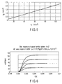
- FIG. 3 shows the relationship between the step desired value r and the gain k2.
- the gains k1, k2 and the settling time have the relationship shown in FIG. 4 and the relationship is graphically represented as shown in FIG. 5. From these figures, the relationship among the desired value r , and the gains k1 and k2 meets J+k1-k2 ⁇
- ⁇ 0. Accordingly, this control system achieves the settling time of 1/10 or less so that its settling time can further be reduced as compared with the conventional control system of the damping coefficient ⁇ 1.
- FIG. 7 shows a control apparatus according to another embodiment of the present invention.
- n (c J+k1) under the desired value r is provided.
- the other elements or configuration parts in this embodiment are similar to those in FIG. 1, like parts are denoted by like reference numerals in FIG. 1 and detailed explanation thereof will be omitted.
- this control apparatus comprises to be similar to that in FIG. 1, the relationship equation of the desired value r , and the gains k1 and k2 results in c-k2
- n J+k1-k2
- FIG. 8 shows a control apparatus according to still another embodiment of the present invention.
- This control apparatus is provided with a control system where a gain K is applied to the controlled system 1, and a gain multiplier 22 having a loop gain kf is added to the outer loop 2 which feeds back the controlled variable, namely speed x from the controlled system 1.
- a gain K is applied to the controlled system 1
- a gain multiplier 22 having a loop gain kf is added to the outer loop 2 which feeds back the controlled variable, namely speed x from the controlled system 1.
- the gain k1 is make large, and the gains k1, k2 and K are set with respect to the desired value r such that a value approaches to J+k1-K ⁇ k2
- n 0 as much as possible, so that the settling time is reduced without overshoot, thereby allowing a high speed response.
- gains and the like are set such that the damping coefficient of the control system meets a positive relationship regardless of the controlled variable, the speed output or the like of the controlled system 1, so that the settling time can largely be reduced without overshoot and a high speed response can be attained.
- a settling time can largely be reduced without overshoot and a high speed response can be realized.
Landscapes
- Engineering & Computer Science (AREA)
- Human Computer Interaction (AREA)
- Manufacturing & Machinery (AREA)
- Physics & Mathematics (AREA)
- General Physics & Mathematics (AREA)
- Automation & Control Theory (AREA)
- Feedback Control In General (AREA)
- Control Of Position Or Direction (AREA)
Abstract
A control apparatus which controls a controlled
system (1) with a transfer function regarded as
a second order system, comprises an outer loop (2)
which performs negative feedback of an output of the
controlled system in order to obtain a deviation
between the output and a desired value, an inner loop
(4) which performs negative feedback of a signal
obtained by multiplying a differential value of the
output of the controlled system by a first gain to the
deviation, and a nonlinear inner feedback loop (10)
which uses the differential value of the output of the
controlled system and a product obtained by multiplying
an absolute value of the deviation e or n-th (n is
an integer) power of the absolute value by the second
gain to perform positive feedback to the deviation.
Description
- The present invention relates to a control apparatus applied to a speed control or a position control in an industrial robot, a numerical control (NC) machine, a head track seeking of a disk drive or the like.
- In general, a servo mechanism using a servo actuator has been widely utilized in a position-to-position high speed positioning control or a high speed tracking control for an industrial robot, a NC machine and the like, and a head track seeking or the like for a hard disk drive or a floppy disk drive used in a data processing unit. In the servo mechanism, a high speed response is one of very important conditions for such a control as a speed control, a positioning control or the like.
- Now, in a control apparatus which controls an object including a servo mechanism having various transfer functions of secondary delay, it has been known that the settling time becomes a minimum time, when a critical damping wherein a damping coefficient of a control system constructing a control apparatus becomes 1 is made under a condition that an overshoot does not occur. That is, in a conventional control system constructed by an inner loop for a negative feedback of an output and another inner loop for negative-feeding back the product of the differential value of the output and a gain, the settling time may be set to be minimum by setting the gain in the another inner value in a proper value. Namely, the response of the control system of the conventional control apparatus is expressed by the following differential equation (1).
- Therefore, the gain k1 can be set such that the damping coefficient ξ = J+k1/2
- Accordingly, in a field that the settling time is set to be shorter than that at the time of the critical damping and the high speed response is required, a new control approach is required. In a case that such a control system is constituted on the basis of the following equation (2),
- An object of the present invention is to provide a control apparatus which reduces the settling time largely without occurrence of an overshoot and which achieves a high speed response.
- According to an aspect of the invention, there is provided a control apparatus which controls a controlled system with a transfer function regarded as a secondary delay system. The control apparatus comprises an outer loop for a negative feedback of an output x of the controlled system in order to obtain an error e between the output x and a desired value r; a first inner loop for a negative feedback of a signal k1·(dx/dt) obtained by multiplying a differential value (dx/dt) of the output x of the controlled system by a gain k1 to the deviation e; and a second inner loop for a positive feedback of a signal of k2(dx/dt) · |e| or k2(dx/dt)·|e|n to the error e, using the differential value (dx/dt) and the product obtained by multiplying an absolute value |e| of the deviation e or n-th power (n: integer) of the absolute value |e| by a gain k2.
- According to the above configuration based on an aspect of the present invention, if the gains k1 and k2 are set so as to meet a predetermined conditional expression of damping coefficients of a control system which are zero and positive, the settling time can be reduced largely and a high speed response can be achieved without occurrence of an overshoot even in a control system having a controlled system with a transfer function regarded as an secondary delay.
- This summary of the invention does not necessarily describe all necessary features so that the invention may also be a sub-combination of these described features.
- The invention can be more fully under stood from the following detailed description when taken in conjunction with the accompanying drawings, in which:
- FIG. 1 is a block diagram of a control apparatus according to an embodiment of the present invention;
- FIG. 2 is a graph showing the step response of the control system of n = 1 in speed control of an AC servo motor of 500W;
- FIG. 3 is a graph showing the relationship between a desired value r and a gain k2 under the same conditions as those in FIG. 2;
- FIG. 4 is a graph showing the relationship among the gains k1, k2 and a settling time at a time of the set point r = 6000 rpm;
- FIG. 5 is a graph showing the relationship between the gains k1 and k2 for performing the setting without overshooting;
- FIG. 6 is a graph showing a step response of the control system of n = 2 in speed control of an AC servo motor of 500W;
- FIG. 7 is a block diagram of the control apparatus according to another embodiment of the present invention; and
- FIG. 8 is a block diagram of the control apparatus according to another embodiment of the present invention.
-
- Embodiments of the present invention will be explained below with reference to the drawings.
- FIG. 1 shows a control apparatus according to the embodiment of the present invention and applied to a speed control system having the controlled system regarded as a second order system. In, for example, a servo mechanism using a servo actuator, a speed control system having an inertia moment or a mass wherein a torque or a thrust generator is approximated with the first order lag element, a position control system wherein a speed controller is approximated with the first order element, or the like is exemplified as a controlled system regarded as the second order system.
- This control apparatus comprises a multi-closed loop control system. In other words, the control apparatus comprises an outer loop 2, an inner loop 4 and a nonlinear inner feedback loop 10. The outer loop 2 executes a negative feedback of an output from a controlled system 1, and includes a deviation computing unit 3 which computes the deviation between a desired value r and a controlled variable, namely the output x which is the signal of the outer loop 2. The inner loop 4 executes a negative feedback of the product between a differential value of the controlled variable, namely the speed x and a gain k1, that is, a compensation signal to a transient change.
- A compensation unit 5 performs such a processing that the deviation from the deviation computing unit 3 is cancelled by the compensation signal from the inner loop 4, and a nonlinear inner feedback loop 10.
- The inner loop 4 comprises a computing unit 6 having a laplace operator s which takes out the differentiated output of the controlled variable or the output x of the controlled system 1 and a gain multiplier 7 which multiplies a proper gain k1 to the differentiated output from the computing unit 6 for a feedback. The inner loop 4 generates the compensation signal for the transient change of the controlled variable or the output x. Incidentally, J in the transfer function of the controlled system 1 is an inertial moment, T is a time constant, and s is a laplace operator unit.
- Such a control apparatus can control the output of the controlled system 1 to a transient change by setting the gain k1 multiplied to the differentiation of the controlled variable, namely output x of the controlled system 1 properly using the inner loop 4 to conduct compensation through a feedback.
- The nonlinear inner feedback loop 10 forms an inner positive feedback loop comprising a laplace operator unit 11, an absolute computing unit 12, a gain computing unit 13, and a positive feedback unit 14. The laplace operator unit 11 outputs the differential value of the controlled variable, namely speed x of the controlled system 1, The absolute computing unit 12 computes the absolute value of the deviation e(r-x) obtained by the deviation computing unit 3 or n-th (n=1, 2, 3, ···) power of the absolute value. The gain computing unit 13 multiplies the computation output of the computing unit 12 by a gain k2. The positive feedback unit 14 executes the positive feedback of the product of the output of the gain computing unit 13 and the differential value of the controlled variable or speed x to the compensation unit 5. The nonlinear inner feedback loop 10 serves so as to change the damping coefficient ξ of the control system according to the deviation e from the deviation computing unit 3.
- Meanwhile, the inner loop 4 performs the negative feedback of the product of the speed differentiation and the gain and it plays a roll for determining a damping coefficient at a time of a steady state. Therefore, the response of the control system shown in FIG. 1 is expressed by the following differential equation (3).
- The damping coefficient is represented in the following equation (4).
- Now, ξ * ≧ 0 is assumed from the equation (4) regardless of the controlled variable, namely speed x of the controlled system 1. That is, when the desired value r, and the gains k1 and k2 are determined under such conditions that J+k1-k2·|r|n ≧ 0 is met in the equation (4), the settling time can be reduced without any overshoot.
- FIG. 2 shows a step response of the speed control system using an AC servo motor of 500 W (J = 0.1 × 10⁻³kgm2, T=10ms) and n=1. Particularly, FIG. 2 shows the step response obtained when k1 is set to be ξ *=1 in a steady state, and for the desired set value r the gain k2 falling in a range in which any overshoot does not occur are set. FIG. 3 shows the relationship between the step desired value r and the gain k2.
- Also, for example, in a case of J+k1 = c, when the condition of c-k2|r| ≧ 0 is met according to ξ * ≧ 0 shown with the equation (4), a step response having a settling time shorter than that in a conventional second order control system can be obtained without any overshoot. In FIG. 3, the section which is defined below a solid line is an area wherein any overshoot does not occur. Incidentally, it has been confirmed that, in a case of the gain coefficient k2 = c/|r|, improvement in settling time can be maximized.
- Regarding a rated set point (3000 rpm), when the present speed control system is set to k2 = 3 X 20-5 and the damping coefficient ξ = ξ * = 1 in the steady state by changing the damping coefficients, the present speed control system can be improved 70% in the settling time in comparison with the conventional speed control system of the damping coefficient ξ = 1.
- Furthermore, when the gain k1 is set so as to meet the damping coefficient ξ = ξ * ≧ 1 in the steady state and the gain k2 is set so as to meet the condition of J + k1-k2 |r| ≧ 0, the control system with the condition thus set can further reduce the settling time when compared with the control system of the damping coefficient ξ = ξ * = 1.
- Also, when the desired value r=6000 rpm is set, the gains k1, k2 and the settling time have the relationship shown in FIG. 4 and the relationship is graphically represented as shown in FIG. 5. From these figures, the relationship among the desired value r, and the gains k1 and k2 meets J+k1-k2·|r|≒0. Accordingly, this control system achieves the settling time of 1/10 or less so that its settling time can further be reduced as compared with the conventional control system of the damping coefficient ξ = 1.
- Next, in a control system where n = 2 is set in the nonlinear inner feedback loop 10, the damping coefficient is expressed by the following equation (5).
- When the desired value r, and the gains k1 and k2 are set so as to meet the condition of J+k1-k2·r2 ≧ 0, the response can be improved without overshoot and the settling time can be made smaller than that of the control system of n=1. FIG. 6 shows a step response obtained when r=3000 rpm and k1 = 1.9 × 10⁻³ are set and the gain k2 is changed. The settling time of this control system is improved as compared with the control system of n=1 and the degree of the improvement can achieve about 50 %.
- FIG. 7 shows a control apparatus according to another embodiment of the present invention.
- This embodiment is a control apparatus for a position control system wherein the controlled system 1 is replaced with the controlled system la of a position control model of 1/Js(1+Tps) and an adjusting element 21 which sets the gain k2 to K2=c/|r|n(c=J+k1) under the desired value r is provided. As the other elements or configuration parts in this embodiment are similar to those in FIG. 1, like parts are denoted by like reference numerals in FIG. 1 and detailed explanation thereof will be omitted.
- Since this control apparatus comprises to be similar to that in FIG. 1, the relationship equation of the desired value r, and the gains k1 and k2 results in c-k2 |r|n= J+k1-k2 |r|n ≧ 0, so that overshoot is prevented from occurring and the settling time can be reduced like the case in FIG. 1.
- FIG. 8 shows a control apparatus according to still another embodiment of the present invention. This control apparatus is provided with a control system where a gain K is applied to the controlled system 1, and a gain multiplier 22 having a loop gain kf is added to the outer loop 2 which feeds back the controlled variable, namely speed x from the controlled system 1. As the other elements or configuration parts in this embodiment are similar to those in FIG. 1, like parts are denoted by like reference numerals in FIG. 1 and detailed explanation thereof will be omitted.
- The differential equation showing the response of this control system results in the following equation (6).
- Also, the damping coefficient ξ * of the control system results in ξ *= (J+k1-Kk2|r-K·fx|n)/2(JT)1/2. Therefore, when the gains K, k1 and k2 and the desired value r are set so as to meet J+k1-K·k2 |r|n ≧ 0, the settling time can be reduced. Here, in the section where J+k1-K·k2 |r|n ≧ 0 is met, the gain k1 is make large, and the gains k1, k2 and K are set with respect to the desired value r such that a value approaches to J+k1-K·k2 |r|n = 0 as much as possible, so that the settling time is reduced without overshoot, thereby allowing a high speed response.
- Thus, according to the above embodiments, by adding a nonlinear inner positive feedback loop to a control system on the basis of the conventional control system, gains and the like are set such that the damping coefficient of the control system meets a positive relationship regardless of the controlled variable, the speed output or the like of the controlled system 1, so that the settling time can largely be reduced without overshoot and a high speed response can be attained.
- As set forth above, according to the present invention, a settling time can largely be reduced without overshoot and a high speed response can be realized.
Claims (14)
- A control apparatus for controlling a control system having a transfer function regarded as a second order system, characterized by comprising:outer loop means (2) for executing a negative-feedback of an output x of the controlled system (1) to obtain a deviation e between the output x and a desired value r;first inner loop means (4) for executing a negative-feedback of a signal k1 (dx/dt), obtained by multiplying a gain k1 to a differentiated value (dx/dt) of the output x of the controlled system, to the deviation e; andsecond inner loop means (10) for using the differentiated value (dx/dt) of the output x of the controlled system and a product, obtained by multiplying a gain k2 to an absolute value |e| of the deviation e or n powers (n: integer) of the absolute value |e|, to execute the positive feedback of a signal of k2(dx/dt) · |e| or k2(dx/dt) · |e|n to the deviation e,the controlled system being controlled using a signal which is fed back through the first and the second inner loop means.
- A control apparatus according to claim 1, characterized in that, when the controlled system includes a position control model, an adjusting element (21) which changes the gain k2 to c / |r| or c / |r|n based on the desired value r is provided.
- A control apparatus according to claim 1, characterized in that a loop gain is inserted in the outer loop means (2), when the controlled system has a transfer function with a proportional gain.
- A control apparatus according to claim 1, characterized in that the gains k1 and k2 are set to values meeting the following equation of damping coefficients of the control system which are zero and positive:
J+k1-k2 |r|≧0 or J+k1-k2 |r|n≧0, where J is a constant determined due to the controlled system with a secondary delay. - A control apparatus according to claim 4, characterized in that, when the controlled system includes a position control model, an adjusting element which changes the gain k2 to c/|r| or c/|r|n based on the desired value r is provided.
- A control apparatus according to claim 4, characterized in that, when the controlled system has a transfer function including a proportional gain, a loop gain is inserted in the outer loop means (2).
- A control apparatus characterized by comprising:outer feedback loop means (2) for performing negative feedback of an output from a controlled system;deviation computing means (3) for computing a deviation between a desired value and a controlled variable or output of the outer feedback loop;first inner feedback loop means (4) for performing negative feedback of a product of a differential value of the controlled variable or speed and a gain;compensation means (5) for performing processing for canceling the deviation from the deviation computing unit by a compensation signal from the first inner feedback loop means; andsecond inner feedback loop means (10) for changing a damping coefficient of a control system according to the deviation from the deviation computing means.
- A control apparatus according to claim 7, characterized in that the controlled system includes a gain K, and the outer feedback loop means (2) includes a gain computing element (13) which multiplies the output of the controlled system by a loop gain Kf to perform feedback of the product.
- A control apparatus according to claim 7, characterized in that the second inner feedback loop means (10) comprises a laplace operator (11) which outputs a differential value of a controlled variable or speed of the controlled system, an absolute value computing element (12) for computing an absolute value of the deviation obtained from the deviation computing element or n-th (n=1, 2, 3, ···) power of the absolute value, a gain computing element (13) for multiplying the computation output of the absolute value computing element with another gain, and a positive feedback element which performs positive feedback of a product of the output of the gain computing element and a differential value of the controlled variable or speed to the compensation element.
- A control apparatus according to claim 9, characterized in that the controlled system includes a gain K, and the outer feedback loop means (2) includes a gain computing element (22) for multiplying the output of the controlled system by a loop gain Kf to perform feedback of the product.
- A control apparatus according to claim 7, characterized in that the first inner feedback loop means (4) comprises a computing element having a laplace operator (6) for taking out a differential output of the controlled variable or output of the controlled system, and a gain computing element (7) for multiplying the differential output from the computing element by the gain to obtain the product.
- A control apparatus according to claim 11, characterized in that the controlled system includes a gain K, and the outer feedback loop means (2) includes a gain computing element (22) for multiplying the output of the controlled system by a loop gain Kf to perform feedback of the product.
- A control apparatus according to claim 11, characterized in that the second inner feedback loop (10) comprises a laplace operator (11) for outputting a differential value of a controlled variable or speed of the controlled system, an absolute value computing element (12) for computing an absolute value of the deviation obtained from the deviation computing element or n-th (n=1, 2, 3, ···) power of the absolute value, a gain computing element (13) for multiplying the computation output of the absolute value computing element with another gain, and a positive feedback element (14) for performing positive feedback of a product of the output of the gain computing element and a differential value of the controlled variable or speed to the compensation element.
- A control apparatus according to claim 13, characterized in that the controlled system includes a gain K, and the outer feedback loop (2) includes a gain computing element (22) for multiplying the output of the controlled system by a loop gain Kf to perform feedback of the product.
Applications Claiming Priority (2)
| Application Number | Priority Date | Filing Date | Title |
|---|---|---|---|
| JP2000178535A JP3297739B2 (en) | 2000-06-14 | 2000-06-14 | Control device |
| JP2000178535 | 2000-06-14 |
Publications (1)
| Publication Number | Publication Date |
|---|---|
| EP1164448A2 true EP1164448A2 (en) | 2001-12-19 |
Family
ID=18679946
Family Applications (1)
| Application Number | Title | Priority Date | Filing Date |
|---|---|---|---|
| EP01114340A Withdrawn EP1164448A2 (en) | 2000-06-14 | 2001-06-13 | Control apparatus |
Country Status (3)
| Country | Link |
|---|---|
| US (1) | US6920362B2 (en) |
| EP (1) | EP1164448A2 (en) |
| JP (1) | JP3297739B2 (en) |
Cited By (1)
| Publication number | Priority date | Publication date | Assignee | Title |
|---|---|---|---|---|
| GB2574861A (en) * | 2018-06-20 | 2019-12-25 | Univ Of Salford Enterprises Limited | Improvements in or relating to robot grippers |
Families Citing this family (5)
| Publication number | Priority date | Publication date | Assignee | Title |
|---|---|---|---|---|
| EP1317107B1 (en) * | 2001-11-30 | 2005-08-03 | Freescale Semiconductor, Inc. | Power amplifier transient compensation in OFDM systems |
| US7355364B2 (en) * | 2005-09-29 | 2008-04-08 | Honda Motor Co., Ltd. | Motor and controller inversion: commanding torque to position-controlled robots |
| US8401676B2 (en) * | 2010-08-18 | 2013-03-19 | International Business Machines Corporation | Performance improvement of signal transformation schemes for ultra-fast scanning |
| JP7238461B2 (en) * | 2019-02-25 | 2023-03-14 | 株式会社島津製作所 | Valve controller and vacuum valve |
| CN113992104A (en) * | 2021-10-22 | 2022-01-28 | 上海艾为电子技术股份有限公司 | Transfer function determination and driving method and system of motor and electronic equipment |
Family Cites Families (6)
| Publication number | Priority date | Publication date | Assignee | Title |
|---|---|---|---|---|
| US4346433A (en) * | 1980-03-11 | 1982-08-24 | Phillips Petroleum Company | Process control |
| JPS57199004A (en) * | 1981-06-01 | 1982-12-06 | Toshiba Corp | Sample value adaptive process controller |
| US5019958A (en) * | 1990-02-12 | 1991-05-28 | Varga Ljubomir D | Generalized synthesis of control systems of zero-order/instantaneous response and infinite disturbance rejection ratio |
| US5200681A (en) * | 1990-03-09 | 1993-04-06 | Kabushiki Kaisha Toshiba | Process control system |
| US5034872A (en) * | 1990-08-09 | 1991-07-23 | Losic Novica A | Current-free synthesis of improved parameter-free zero-impedance converter |
| US5282129A (en) * | 1991-03-04 | 1994-01-25 | Losic Novica A | Control basic building block (CBBB) |
-
2000
- 2000-06-14 JP JP2000178535A patent/JP3297739B2/en not_active Expired - Lifetime
-
2001
- 2001-06-13 EP EP01114340A patent/EP1164448A2/en not_active Withdrawn
- 2001-06-13 US US09/879,158 patent/US6920362B2/en not_active Expired - Fee Related
Cited By (1)
| Publication number | Priority date | Publication date | Assignee | Title |
|---|---|---|---|---|
| GB2574861A (en) * | 2018-06-20 | 2019-12-25 | Univ Of Salford Enterprises Limited | Improvements in or relating to robot grippers |
Also Published As
| Publication number | Publication date |
|---|---|
| US6920362B2 (en) | 2005-07-19 |
| JP3297739B2 (en) | 2002-07-02 |
| US20010053941A1 (en) | 2001-12-20 |
| JP2001356823A (en) | 2001-12-26 |
Similar Documents
| Publication | Publication Date | Title |
|---|---|---|
| EP0311127B1 (en) | Control device for servo motor | |
| EP0494500A1 (en) | Sliding mode control system | |
| EP0817377A2 (en) | Increased bandwidth for plants with resonant modes using nonlinear notch filters | |
| US6998810B2 (en) | Position controller of feed shaft | |
| CA2057237C (en) | Sliding mode control system | |
| JPS615302A (en) | Controller of manipulator | |
| EP1164448A2 (en) | Control apparatus | |
| JP3943061B2 (en) | Servo control device | |
| JPH086603A (en) | Adjusting method for servo system and its servo controller | |
| JP3413579B2 (en) | Rotation speed control device | |
| JP2999330B2 (en) | Control method using sliding mode control system | |
| JPH08331879A (en) | Mechanical constant estimation circuit | |
| JP3541857B2 (en) | Overshootless auto tuning method | |
| Albagul | Performance improvement of practical control method for positioning systems in the presence of actuator saturation | |
| JP3247295B2 (en) | Servo device | |
| JPH10161706A (en) | Simply adaptive controller | |
| US20240217348A1 (en) | Adaptive speed control system and method for adapting motor control to changing load conditions | |
| JPH08297512A (en) | Method for positioning control by sliding mode control | |
| JP3427944B2 (en) | Trajectory tracking positioning control method | |
| JP3324482B2 (en) | Position control device | |
| JP2850076B2 (en) | Control device | |
| JPH0256601A (en) | Controller for kinetic machine system | |
| JPH11231905A (en) | Simple adaptation control device | |
| JPS60160404A (en) | Automatic tracking system of inertial fluctuation in servo system | |
| JPH01227675A (en) | Motor controller |
Legal Events
| Date | Code | Title | Description |
|---|---|---|---|
| PUAI | Public reference made under article 153(3) epc to a published international application that has entered the european phase |
Free format text: ORIGINAL CODE: 0009012 |
|
| 17P | Request for examination filed |
Effective date: 20010613 |
|
| AK | Designated contracting states |
Kind code of ref document: A2 Designated state(s): AT BE CH CY DE DK ES FI FR GB GR IE IT LI LU MC NL PT SE TR |
|
| AX | Request for extension of the european patent |
Free format text: AL;LT;LV;MK;RO;SI |
|
| STAA | Information on the status of an ep patent application or granted ep patent |
Free format text: STATUS: THE APPLICATION HAS BEEN WITHDRAWN |
|
| 18W | Application withdrawn |
Effective date: 20060419 |