BACKGROUND OF THE INVENTION
Field of the Invention
The present invention relates to measurement of a
position by wireless communication, and more particularly to
a wireless position measurement terminal, and a wireless
position measurement system for terminals and base stations.
Description of the Background
In a typical wireless system, such as a CDMA system,
base stations are used as the basis of transmission and
reception. The delay quantity, i.e. a delay profile, for
communication between a mobile terminal and the base station
varies with the distance between the terminal and the base
station or stations and the path taken by signals between the
terminal and the base stations. For example, a signal
arriving from a distant base station is received at the
terminal after a longer time period following transmission
from that distant base station than is a
signal coming from a nearby base station, and thus will have a
shifted delay profile when compared to the nearby base station,
and a signal following a direct path from the base to the
terminal will have a different delay profile than will a signal
that is reflected to reach the terminal from the base station.
Further, in order to locate the position of a terminal,
the distances, i.e. the delay profiles, from at least three
base stations must be measured, in order to perform a location
via triangulation methods. Thus a sufficient size of a delay
profile sampling window should be secured to allow for the
observation of propagation data between at least three base
stations and the terminal, as discussed further hereinbelow.
Techniques for measuring the position of a terminal using
wide band wireless signals, such as a location system using
code division multiple access (CDMA) signals, are disclosed in
Japanese Published Unexamined Patent Application No. Hei 7-181242.
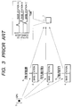
Fig. 3 is an illustration of a delay profile system
disclosed in Japanese Published Unexamined Patent Application
No. Hei 7-181242. Fig. 3 illustrates a terminal 1 that
receives signals 6, 7, 8, such as wideband signals 6,7,8, from
a plurality of base stations 2, 3, 4, wherein the base stations
2,3,4 are synchronized with, for example, the Global
Positioning System (GPS) 5 or the like.
Delay profiles, such as those in Fig. 3, allow for an
estimating of the propagation distance to a terminal of each
wideband signal 6,7,8 from the base stations 2,3,4 respectively,
as discussed hereinabove, and the position of the terminal may
then be estimated using the base station locations and the
estimated distance of the terminal therefrom via triangulation
methods.
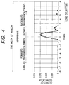
Fig. 4 is a timing diagram illustrating an exemplary
delay profile. A delay profile, as used herein, is a
presentation of a calculated correlation between a transmitted
signal and the pertinent received signal. The delay profile
will vary according to the directness of the path a signal
takes between a base and a terminal, as is known in the art,
and as is discussed hereinabove. Although delay profiles
herein are presented as pure time, it will be apparent to those
skilled in the art that delay profiles may be presented, for
example, as a propagation time basis using an integration of
the delay time with the velocity of light, because the delay
results from the propagation of a wave.
With respect to Fig. 4, due to the receipt of the
received signal at a correlation peak, the received signal may
be used to estimate the propagation time between the base and
the terminal, i.e. the received signal displays the
characteristics of the path and time taken by that signal to
reach the terminal. As shown in Fig. 4, and as mentioned
hereinabove, numerous delay profiles, such as delay profiles of
numerous base stations, may be calculated by a terminal with
respect to a calculation "window", wherein the window includes
a series of samples around a specific reference time. For a
given base station within a window, the results of a
correlation calculation within the window at a time prior to a
high correlation are herein defined as "forward", and the
results of a correlation calculation within the window at a
time following a high correlation are herein defined "backward".
It will be apparent to those skilled in the art that the larger
the window selected, the greater the quantity of calculations
needed to calculate delay profiles within the window.
Where a terminal is in a location where the density of
base stations is unknown, the window must be sufficiently
expanded forward and backward to enable the measurement of at
least three distances even if the base stations are sparsely
distributed, because at least three base station distances are
required to perform a triangulation location. However, in a
location where the density of base stations is unknown, the use
of a large window might prove unnecessary and redundant, and
this use of an unnecessarily large window might additionally
require extensive unnecessary calculations, an increase in
response time, and/or an increase in power consumption.
Therefore, the need exists for a terminal, a system in
which to operate the terminal, and a method of using the
terminal that provides for the calculation of distance of the
terminal from a plurality of base stations, thereby allowing a
calculation of the location of the terminal, but that minimizes
the quantity of calculations necessary to obtain this distance
and location.
SUMMARY OF THE INVENTION
The present invention is directed to a wireless position
measurement terminal that permits changes in the size of the
window for delay profiles according to any then-present
location of the terminal. The wireless position measurement
terminal includes a delay profile calculating circuit that
calculates delay profiles for at least one remote received
signal, and a window setter communicatively connected to the
delay profile calculating circuit, wherein the window setter
sets a range for a delay profile calculating window for the
delay profile calculating circuit. The window setter changes
the range according to at least one information item, and the
at least one information item is within at least one of the at
least one remote received signals. The at least one
information item may, for example, be received from one primary
base station, and may include the range needed for calculation
of the delay profiles of at least two base stations other than
the one primary base station.
The wireless position measurement terminal may
additionally include a memory circuit that stores positional
information of a first plurality of base stations, wherein at
least one base station of the first plurality of base stations
sends the information item to the terminal in one of the at
least one remote received signals. The window setter then
changes the range according to a correlation of the positional
information and the information item.
In one embodiment of the wireless position measurement
terminal, the range is changed by selecting three base stations,
including the base station having maximum power received, and
selecting by the window setter of a range equivalent to an
average distance of the positional information between the
three selected base stations added to a predetermined margin.
Alternatively, the positional information may include one range
each for rural, urban and highly congested areas.
The present invention is also directed to a wireless
position measurement system that performs delay profile
calculation window sizing for a terminal, wherein the window
sizing is correspondent to a population density of base
stations in a then-present location of the terminal. The
system of the present invention includes the terminal, and at
least three base stations, wherein at least one of the at least
three base stations provides at least one signal to the
terminal. At least one of the at least one signals includes at
least one information item. The terminal receives the at least
one signal transmitted from at least one of the at least three
base stations, and estimates the propagation distances between
the terminal and each of the at least three base stations by
calculating the delay profile of each base station. The delay
profiles of all of the at least three base stations are
calculated in a window sized by the terminal according to the
at least one information item. The terminal then triangulates
the then-present location of the terminal based on the three
propagation distances.
The system of the present invention may additionally
include a center, such as a server. The at least one
information item may then be stored in the center, and the
terminal preferably then receives the at least one information
item over a wireless connection with the center via at least
one of the at least one signals.
The present invention is also directed to a method for
performing delay profile calculation window sizing for a
terminal in a wireless position measurement system, wherein the
window sizing is correspondent to a population density of base
stations in a then-present location of the terminal. The
method includes the step of receiving at least one signal at
the terminal from at least one of at least three base stations,
wherein at least one of the at least one signals includes at
least one information item, the step of sizing of a delay
profile calculation window according to the at least one
information item, the step of estimating of propagation
distances between the terminal and each of the at least three
base stations by a calculating of a delay profile of each base
station, wherein the delay profiles of all of the at least
three base stations are calculated in the window sized by the
terminal according to the at least one information item, and
the step of triangulating of the then-present location of the
terminal based on the three propagation distances. The method
may additionally include the steps of storing the at least one
information item in a center, and receiving the at least one
information item over a wireless connection with the center via
at least one of the at least one signals.
Because the wireless position measurement terminal
according to the present invention sets the size of the window
for calculating delay profiles according to the spacing between
the base stations in any then-present location, the window size
in the instance wherein base stations are densely spaced can be
reduced, and many base stations can thereby be observed at high
speed and using minimal processing resources. Further, in the
instance wherein base stations are sparsely distributed,
position measurement can be dependably accomplished by
calculating delay profiles for a small number of base stations
for a longer period using the minimum size window necessary to
perform the position measurement, thereby using minimal
processing resources and providing maximum speed.
Other features and advantages of the present invention
will be apparent from the following detailed description taken
in conjunction with the accompanying drawings.
BRIEF DESCRIPTION OF THE DRAWINGS
For the present invention to be clearly understood and
readily practiced, the present invention will be described in
conjunction with the following figures, wherein like reference
characters designate the same or similar elements, which
figures are incorporated into and constitute a part of the
specification, wherein:
DETAILED DESCRIPTION OF THE INVENTION
It is to be understood that the figures and descriptions
of the present invention have been simplified to illustrate
elements that are relevant for a clear understanding of the
present invention, while eliminating, for purposes of clarity,
many other elements found in a typical telecommunications
system. Those of ordinary skill in the art will recognize that
other elements are desirable and/or required in order to
implement the present invention. However, because such
elements are well known in the art, and because they do not
facilitate a better understanding of the present invention, a
discussion of such elements is not provided herein.
Fig. 5 is a timing diagram illustrating the observation
through a window of propagation data for a plurality of densely
spaced base stations. In the case illustrated in Fig. 5, the
propagation distance of a wave from each base station to the
terminal is short, and distances from different base stations
to the terminal vary little. As a result, the high correlation
portion of each of the delay profiles calculated on the left
side of Fig. 5 is received at the terminal at substantially the
same time. Therefore, the size of the window needed for
profile calculation for the reference timing, i.e. for
reception of the high correlation portion for at least three
base stations, can be relatively small.
Referring to Fig. 5, where the spacing between base
stations is approximately 1 km, it is preferable that, in order
to estimate signal arrival times, correspondent to high
correlation points, for at least three base stations,
observation through a window corresponding to 3 to 6 km, i.e.
at least two and preferably three to six times the spacing from
one selected base station to the next base station, is
performed. Additionally, where the propagation distance is
estimated using a signal of, for example, 1 MHz in chip rate,
and the velocity of light is known to be about 300,000 km/sec,
observation through a window corresponding to 6 km/300,000
km/sec × 1,000,000 Hz = 20 chips ensures that the propagation
signals are received from at least the five base stations of
Fig.5.
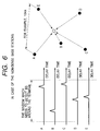
Fig. 6 is a timing diagram illustrating the observation
of propagation data for a plurality of sparsely spaced base
stations. In the embodiment of Fig. 6, if, for example, the
distance from one base station to the next is approximately 10
km, the window necessary to allow for the observation of at
least three base stations might correspond to 40 to 60 km in
terms of propagation distance, according to the criteria
discussed hereinabove, thus requiring a correlation calculation
of as many as 200 chips, according to the calculation
hereinabove.
When a terminal is located where the density of base
stations is unknown, the window is preferably sufficiently
expanded to enable the measurement of at least three distances
(the delay profiles of at least three base stations) even if
the base stations are sparsely distributed. However, in a
location where the density of base stations is unknown, the use
of a large window might prove unnecessary and redundant, and
because this use of a large window might require extensive
unnecessary calculations, an increase in response time, and/or
an increase in power consumption, it is desirable to use a
window properly correspondent to the density of base stations
in any then-present location of the terminal.
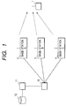
Fig. 1 is a block diagram illustrating a wireless
position measurement system that performs window sizing
correspondent to the density of base stations in a then-present
location. The system includes a terminal 1, and at least three
base stations 2,3,4. The position measurement terminal 1
receives signals transmitted from base stations A 2, B 3 and C
4. The terminal estimates propagation distances by measuring
the delay profile of each base station 2,3,4, and estimates its
own position from the positions of the base stations and the
results of the estimation of the propagation distance that have
been obtained. Because signals arriving from the base stations
are delayed according to the respective propagation distances
of each base station 2,3,4 from the terminal 1, the window size
used to detect at least three delay profiles must be
sufficiently enlarged to allow for the delay profile of the
most distant of the at least three base stations to be
calculated within the window.
In a first preferred embodiment, at least one of base
stations A, B and C, preferably using a common control channel,
such as a synch channel, transmits the following information
items to the terminal 1: (a) the position of the base station;
(b) the transmission timing offset, such as, for example, the
PN offset of the base station in an IS-95 embodiment of the
present invention; and (c) the size of at least one window
needed for calculating delay profiles of that base station and
other base stations in the vicinity of that base station.
Additional information items that may be received at a terminal
from a base station, such as power delivered, will also be
apparent to those skilled in the art, and are included within
the term "information item" as defined herein.
Fig. 7 is a block diagram illustrating a preferred
embodiment of the position measurement terminal for carrying
out the position measurement in the position measurement system
of the present invention. The terminal includes a signal
receiver 20 that converts received RF signals into base band
signals, a delay profile calculator 21, a window setter 22, and
a position calculator 23.
The window setter 22, preferably through a
synchronization with the base station having the highest
received power, for example, receives the control channel, such
as the synch channel, transmitted from that base station, and
acquires the information items (a), (b) and (c) discussed
hereinabove. The window setter 22, on the basis of information
item (c), determines the window through which to search for
delay profiles.
The delay profile calculator 21 may include, for example,
a correlator, or a matched filter. The delay profile
calculator despreads a pilot signal in the search window to
calculate a delay profile. A reference time for the
calculation of a delay profile is determined from the
transmission timing offset information item (b). Item (b)
indicates the transmission time offset value for each
individual base station of mobile communication from the system
standard time. The terminal then estimates the standard time
for the base station system, which is the time, such as GPS,
universal standard time, or synchronized base station to base
station time, to which all base stations are referenced. The
terminal performs this estimation by adding the transmission
timing offset of the base station to be observed to the
standard time of the base station system, thereby generating
the reference time of the base station to be observed. The
window, consisting of forward and backward portions from the
reference time of the base station to be observed, is set
sufficiently forward and backward from the reference time to
allow the calculation of at least two other base station delay
profiles. As used herein, "forward" denotes searching for a
base station at a closer location than the base station to be
referenced, while "backward" denotes searching for a base
station at a farther location than the reference.
In light of the fact that the window size required for
calculating a delay profile is designated according to the base
station in the embodiment of Fig. 1, the terminal performs no
unnecessary processing to calculate the window size required
for calculating the delay profiles of the base stations in the
then-present area.
Returning now to Fig. 7, upon completion of the
calculation of the delay profiles of the necessary at least
three base stations, the terminal calculates the timing of the
path from the base station, based on the peak position of the
delay profile for that base station, and thereby calculates
relative delay, i.e. propagation, times. The position
calculator 23 then calculates the actual position of the
terminal based on the relative delay information and
information item (a), the base station position.
In a second preferred embodiment, at least one item of
information (a), (b) and (c) is stored at a center 12, and the
terminal receives the information via a wireless connection
with the center 12. As illustrated in Fig. 1, the terminal 1
is connected via a wireless connection to at least one of a
series of base stations A, B and C, and, according to the
second preferred embodiment, the terminal may acquire base
station information from a server 12 connected to the base
station via a base station control apparatus 10 and a node 11
on a network, for example. The terminal can then calculate
delay profiles through a selected window based on the
information (a), (b), and (c) received from the center 12
according to the methodology discussed hereinabove with respect
to Fig. 7.
Fig. 2 is a block diagram illustrating a second preferred
embodiment of the position measurement terminal. The terminal
of Fig. 2 includes a signal receiver 20, a delay profile
calculator 21, a window setter 22, a control channel receiver
24, a memory 13, and a position calculator 23. The signal
receiver 20, the delay profile calculator 21, the window setter
22, and the position calculator 23 are substantially as
discussed hereinabove with respect to Fig. 7.
Memory 13 is a memory device as is known in the art, such
as a ROM or RAM device, and is within, or in communication with,
terminal 1. In an embodiment wherein terminal 1 frequently
performed position measurement, processing time can be limited
where the aforementioned base station information item or items
are included in the memory 13 at, or in communication with, the
terminal. When base station information item (a) and/or (b)
and/or (c) is included in a memory at or in communication with
the terminal, communication with a base station is necessary on
a less frequent basis. Once the use of memory 13 is
initialized by the terminal 1, the terminal 1 can obtain
information items (a) and/or (b) and/or (c) from at least one
local base station, or by an inquiry to the center 12, and the
terminal 1 can then accumulate the information (a) and/or (b)
and/or (c) in the memory 13. In a subsequent instance wherein
it becomes necessary for the terminal 1 to perform position
measurement, the window setter 22 then selects a window based
on information in the memory.
In operation of the window setter based on information in
the memory, the terminal selects, for example, the base station
having the highest received power, and, with reference to that
base station, the terminal selects the base stations
surrounding the maximum power base station to be observed
within the window using the positional information on the
location of a plurality of base stations held in the memory
from prior use. Alternatively, the memory may be programmed
with this positional information prior to use. For example,
the memory may have stored therein a list of base stations,
which base stations will include a list of base stations
nearest in distance to a selected primary reference base
station, such as a then-maximum power base station.
In a preferred embodiment, the terminal receives, or has
stored in memory, the timing offset information of the primary
reference base station, and estimates the standard time of the
base station system therefrom. For example, the standard time
may be the difference in the current time less the timing, such
as the PN, offset. This exemplary embodiment therefore uses
difference timing, although alternative base station timing
methods will be apparent to those skilled in the art.
The window size may alternatively be empirically
determined by the terminal according to the distances between
the base stations. If, for example, the average distance
between selected base stations in memory 13 is 4 km, the
distance between the base station to be referenced and the
terminal, though it is unknown, can, for example, be assumed to
be not greater than the average distance between th reference
base station and other selected base stations, due to the fact
that it is known that the base station to be referenced is
providing the maximum power signal, and thus is likely the
nearest, or one of the nearest, base stations to the terminal.
Therefore, a window equivalent to a 4 km propagation delay
forward is selected. Since it is possible for the difference
in distance to the terminal from one base station to be greater
than the propagation distance between base stations, a base
station spacing plus a predetermined margin is preferably
selected as the backward part of the window. Several sample
measurements, for example, would be sufficient to select this
predetermined margin, and the manner of taking of these sample
measurements will be apparent to those skilled in the art.
Using the empirical methodology discussed immediately
hereinabove, the terminal generates a window suitable in size
for calculating the necessary at least three delay profiles
without having to obtain information from the base station(s).
This elimination of the need to contact the base station(s) for
information items results in faster processing by the terminal,
because information concerning the base stations and/or the
window need not be obtained from the base stations and/or the
center each time position measurement is to be performed. It
will additionally be apparent to those skilled in the art that,
where the base station to be referenced remains the same as an
earlier instance of position measurement, the same settings as
those used in the earlier instance may be used without any
additional or new calculations by the terminal concerning base
stations or window size.
In an additional preferred embodiment of the operation of
the system of the present invention, the correlation of the
electric field intensity of signals arriving from each base
station to the distance between the base station and the
position of measurement itself allows the position of
measurement to be approximately calculated. For example, the
weighted center at a terminal position can be calculated by
averaging the position vectors representing the positions of
the base stations, weighted in proportion to the electric field
intensity of the base station, thereby approximately indicating
the terminal position. Using this weighting, the accuracy of
estimating the distance of the terminal from each base station
can be enhanced, thereby allowing for further reduction in the
window size needed to calculate delay profiles.
Further, it will be apparent to those skilled in the art
that position measurement may be performed by detecting the
shortest forward path between a base station and the terminal,
because the shortest forward path can be deemed to be a direct
path. Therefore, once detection of the shortest forward path
is completed, no further calculation of delay profile is
necessary. Consequently, the calculation of delay profiles is
begun in the forward portion of the window, and the calculation
of the delay profile of a particular base station is completed
when the first path is confirmed. In this manner, the
processing used to calculate delay profiles can be further
reduced.
The embodiments discussed hereinabove are exemplary
embodiments in which the window size for calculating delay
profiles is either designated by a base station, or designated
by a center, or calculated by the terminal. However, the
problem solved by each of these exemplary embodiments is that
only a small window is needed for calculating delay profiles in
the instance wherein base stations are densely spaced, while a
larger window is needed in the instance wherein base stations
are sparsely spaced. Therefore, methods other than those
discussed hereinabove, such as, for example, the use of window
sizes determined in advance for rural, urban and highly
congested areas, and additional methods wherein the calculation
of delay profiles varies with the geographic location of the
terminal, are also contemplated within the scope of the present
invention.
The use of the present invention reduces the quantity of
processing needed for the calculation of delay profiles in
wireless position measurements, and thereby reduces system
response time and terminal power consumption. Other advantages
and benefits of the present invention will be apparent to those
skilled in the art.
The present invention is not limited in scope to the
embodiments discussed hereinabove. Various changes and
modifications will be apparent to those skilled in the art, and
such changes and modifications fall within the spirit and scope
of the present invention. Therefore, the present invention is
to be accorded the broadest scope consistent with the detailed
description, the skill in the art and the following claims.