EP1164352A1 - Position sensing method and position sensor, exposing method and exposing apparatus, and device and device manufacturing method - Google Patents
Position sensing method and position sensor, exposing method and exposing apparatus, and device and device manufacturing method Download PDFInfo
- Publication number
- EP1164352A1 EP1164352A1 EP00903969A EP00903969A EP1164352A1 EP 1164352 A1 EP1164352 A1 EP 1164352A1 EP 00903969 A EP00903969 A EP 00903969A EP 00903969 A EP00903969 A EP 00903969A EP 1164352 A1 EP1164352 A1 EP 1164352A1
- Authority
- EP
- European Patent Office
- Prior art keywords
- measurement
- points
- measurement point
- estimations
- parameters
- Prior art date
- Legal status (The legal status is an assumption and is not a legal conclusion. Google has not performed a legal analysis and makes no representation as to the accuracy of the status listed.)
- Withdrawn
Links
Images




Classifications
-
- G—PHYSICS
- G01—MEASURING; TESTING
- G01B—MEASURING LENGTH, THICKNESS OR SIMILAR LINEAR DIMENSIONS; MEASURING ANGLES; MEASURING AREAS; MEASURING IRREGULARITIES OF SURFACES OR CONTOURS
- G01B11/00—Measuring arrangements characterised by the use of optical techniques
-
- G—PHYSICS
- G03—PHOTOGRAPHY; CINEMATOGRAPHY; ANALOGOUS TECHNIQUES USING WAVES OTHER THAN OPTICAL WAVES; ELECTROGRAPHY; HOLOGRAPHY
- G03F—PHOTOMECHANICAL PRODUCTION OF TEXTURED OR PATTERNED SURFACES, e.g. FOR PRINTING, FOR PROCESSING OF SEMICONDUCTOR DEVICES; MATERIALS THEREFOR; ORIGINALS THEREFOR; APPARATUS SPECIALLY ADAPTED THEREFOR
- G03F9/00—Registration or positioning of originals, masks, frames, photographic sheets or textured or patterned surfaces, e.g. automatically
- G03F9/70—Registration or positioning of originals, masks, frames, photographic sheets or textured or patterned surfaces, e.g. automatically for microlithography
- G03F9/7003—Alignment type or strategy, e.g. leveling, global alignment
- G03F9/7046—Strategy, e.g. mark, sensor or wavelength selection
-
- G—PHYSICS
- G03—PHOTOGRAPHY; CINEMATOGRAPHY; ANALOGOUS TECHNIQUES USING WAVES OTHER THAN OPTICAL WAVES; ELECTROGRAPHY; HOLOGRAPHY
- G03F—PHOTOMECHANICAL PRODUCTION OF TEXTURED OR PATTERNED SURFACES, e.g. FOR PRINTING, FOR PROCESSING OF SEMICONDUCTOR DEVICES; MATERIALS THEREFOR; ORIGINALS THEREFOR; APPARATUS SPECIALLY ADAPTED THEREFOR
- G03F9/00—Registration or positioning of originals, masks, frames, photographic sheets or textured or patterned surfaces, e.g. automatically
- G03F9/70—Registration or positioning of originals, masks, frames, photographic sheets or textured or patterned surfaces, e.g. automatically for microlithography
- G03F9/7003—Alignment type or strategy, e.g. leveling, global alignment
-
- G—PHYSICS
- G03—PHOTOGRAPHY; CINEMATOGRAPHY; ANALOGOUS TECHNIQUES USING WAVES OTHER THAN OPTICAL WAVES; ELECTROGRAPHY; HOLOGRAPHY
- G03F—PHOTOMECHANICAL PRODUCTION OF TEXTURED OR PATTERNED SURFACES, e.g. FOR PRINTING, FOR PROCESSING OF SEMICONDUCTOR DEVICES; MATERIALS THEREFOR; ORIGINALS THEREFOR; APPARATUS SPECIALLY ADAPTED THEREFOR
- G03F9/00—Registration or positioning of originals, masks, frames, photographic sheets or textured or patterned surfaces, e.g. automatically
- G03F9/70—Registration or positioning of originals, masks, frames, photographic sheets or textured or patterned surfaces, e.g. automatically for microlithography
- G03F9/7092—Signal processing
Definitions
- the present invention relates to a position detection method and position detector, an exposure method and exposure apparatus, and a device and device manufacturing method and, more particularly, to a position detection method and position detector for obtaining arrangement information of divided areas on an object, an exposure method and exposure apparatus using the position detection method, and a device manufactured using the exposure method and a manufacturing method thereof.
- an exposure apparatus which transfers a pattern formed on a mask or reticle (to be generally referred to as a "reticle” hereinafter) onto a substrate (to be referred to as a "sensitive substrate or wafer” as needed hereinafter) such as a wafer, glass plate, or the like coated with a resist or the like via a projection optical system is used.
- a mask or reticle to be generally referred to as a "reticle” hereinafter
- a substrate to be referred to as a "sensitive substrate or wafer” as needed hereinafter
- stationary exposure type projection exposure apparatus such as a so-called stepper, or a scanning exposure type projection exposure apparatus such as a so-called scanning stepper is mainly used.
- position adjustment between a reticle and wafer must be accurately performed prior to exposure.
- position detection marks are formed (transferred by exposure) in the previous lithography process on the wafer in each of shot regions, and the position of the wafer (or a circuit pattern on the wafer) can be detected by detecting the positions of the alignment marks. Alignment is performed on the basis of the detection results of the positions of the wafer (or a circuit pattern on the wafer).
- Such alignment schemes include a die-by-die scheme for performing alignment by detecting alignment marks in each shot, and an enhanced global alignment (to be abbreviated as "EGA" hereinafter) scheme for, after measuring alignment marks (position adjustment marks transferred together with a circuit pattern) at several positions in a wafer, computing arrangement coordinate positions of each shot area by a statistical scheme such as a least square approximation and, upon exposure, stepping a wafer using the accuracy of a wafer stage and the computation result.
- EGA enhanced global alignment
- This EGA scheme is disclosed in, e.g., Japanese Patent Laid-Open No. 61-44429 and corresponding U.S. Patent No. 4,780,617. Of these schemes, the EGA scheme is prevalently used nowadays in terms of the throughput of the apparatus.
- Prior art 2 is free from any problem of the accuracy of the arrangement coordinate position determination of shot areas unlike in prior art 1.
- prior art 2 requires a huge computation volume for fuzzy inference, a long period of time is required to determine the arrangement coordinate positions of shot regions, and this makes it difficult to improve the throughput of exposure.
- a large-scale computation resource is needed.
- the use thereof causes the whole exposure apparatus to be large and complicated.
- a sample set of alignment marks as a subset of a set of all alignment marks is determined by an aleatory method, and the validity of determination of that sample set is not quantitatively evaluated. Therefore, it is not guaranteed that the error distribution of the positions of a plurality of alignment marks as elements of a sample set determined by the conventional method appropriately reflects the error distribution of positions of all alignment marks.
- sample set In the case where a wafer is aligned on the basis of the position measurement results of alignment marks included in a subset (sample set) selected from a large number of alignment marks, upon examining the validity of a method for selecting the desired sample set, evaluating separately individual alignment marks in the sample set does not have much sense. This is because it is ideal that the sample set broadly reflects the entire set and because it is preferable that alignment marks in the sample set preferably have a position distribution that corresponds to that of alignment marks in the entire set. For example, in the case where one of five alignment marks in a sample set is an alignment mark contained in an isolated shot region, if one fifth of all the alignment marks are contained in isolated shot regions, the sample set is more valid than a sample set excluding alignment marks of isolated shot regions.
- a second object of the present invention is to provide an exposure method and exposure apparatus that can transfer a predetermined pattern onto a substrate with high accuracy.
- a fourth object of the present invention is to provide a manufacturing method of manufacturing a device on which fine patterns are accurately formed.
- a first position detection method for detecting position information of any area on an object provided with a plurality of position-measurement-points, the position detection method comprising a measurement step of selecting more position-measurement-points than a minimum number of measurements required to calculate values of a predetermined number of parameters, which uniquely specify position information of any area on the object, from the plurality of position-measurement-points and measuring pieces of position information of the respective selected position-measurement-points; an estimation step of calculating respective positions of the selected position-measurement-points, based on the measurement results of the pieces of position information, and estimating probability density functions which each represent occurrence probability of the calculated position for respective one of the selected position-measurement-points; a probability density calculation step of calculating probability density of the calculated position of each of the position-measurement-points, based on respective one of the probability density functions; and a parameter calculation step of evaluating an error of each calculated position relative to respective reference position while using the respective calculated probability density's value as
- the probability density of each calculated mark (a position-measurement-point) position directly reflects the certainty of a respective mark position. Therefore, in the first position detection method of the present invention, the errors are evaluated by multiplying the errors of the calculated positions relative to the respective reference positions by the respective probability densities of the calculated positions.
- position measurement marks can be formed at the position-measurement-points.
- the position of each position-measurement-point can be measured by detecting a respective position measurement mark.
- the position measurement mark can be, e.g., a line-and-space mark, box-in-box mark, and the like.
- a plurality of position detection marks formed at the plurality of position-measurement-points can include a first number of first marks, of which surface states change in a first direction, and the position information of each first mark measured in the measurement step can be position information of a plurality of feature portions in the first direction of each first mark.
- the position of a first mark in the first direction can be calculated by measuring and processing the position information of the first mark.
- a probability density function that represents the occurrence probability of the calculated position can be estimated based on its design reference position and measured position information.
- the average value of positions of a plurality of feature portions in the first direction such as the boundaries between lines and spaces, which represents the central position of the first mark, can be used as the position of the first mark, and the probability density function that represents the occurrence probability of the central position can be estimated.
- the position information of each selected first mark can be measured in the measurement step at a plurality of positions in a direction perpendicular to the first direction.
- the position of the first mark in the first direction can be accurately calculated, and the probability density function that represents the occurrence probability of the calculated position can be accurately estimated.
- the measurement step for each selected first mark, at least one of position information in the first direction of a plurality of feature portions in the first direction and position information in the second direction of a plurality of feature portions in the second direction can be measured.
- the position of the first mark in a direction in which the number of pieces of position information to be processes has increased can be accurately calculated, and the probability density function that represents the occurrence probability of the calculated position can be accurately estimated.
- the plurality of marks can further include a second number of second marks, of which surface states change in a second direction different from the first direction, and the position information of each second mark measured in the measurement step can be position information of a plurality of feature portions in the second direction of the second mark.
- the position of the second mark in the second direction can be calculated by measuring and processing position information of the second mark in the same manner as for the first mark, and a probability density function that represents the occurrence probability of the calculated position can be estimated based on its design reference position and measured position information. That is, information that pertains to a two-dimensional position of the object can be calculated.
- the position information of each selected second mark can be measured at a plurality of positions in a direction perpendicular to the second direction.
- the position of the second mark in the second direction can be accurately calculated, and the probability density function that represents the occurrence probability of the calculated position can be accurately estimated.
- a plurality of divided areas can be arranged on an object, and position measurement marks can be contained in each of the plurality of divided areas.
- the arrangement coordinate position of each divided area on the object can be accurately detected.
- the predetermined number of parameters can include parameters associated with representative points of the plurality of divided areas.
- the arrangement of the representative points, e.g. the central points, of the plurality of divided areas on the object can be calculated, the arrangement being referred to as an arrangement coordinate system.
- the predetermined number of parameters can further include parameters associated with points other than the representative points of the plurality of divided areas.
- a divided area coordinate system that specifies the direction of pattern transfer, scale, and the like on the divided areas can be calculated.
- a second position detection method for detecting position information of any area on an object provided with a first number of position-measurement-points, the position detection method comprising a first step of selecting a plurality of measurement point subsets which each consist of a third number of position-measurement-points and are different from one another, the third number being larger than a second number and smaller than the first number, the second number being a minimum number of measurement points required to calculate a predetermined number of parameters that uniquely specify position information of any area on the object; and a second step of statistically calculating, for each of the plurality of measurement point subsets, estimations of the predetermined number of parameters and certainty of the estimations, based on measurement results of the third number of position-measurement-points.
- the certainty of the estimations of the predetermined number of parameters is calculated using the calculated estimations, and is determined in accordance with position errors of position-measurement-points, which are used to calculate the estimations, relative to respective expected positions. If the deviation of position errors of the position-measurement-points used to calculate the estimations is large, the certainty is low; if the deviation of the position errors is small, the certainty is high.
- a plurality of different measurement point subsets are selected, and for each of the measurement point subsets, estimations and their certainty of the predetermined number of parameters which uniquely specify position information of any area on an object are statistically calculated.
- the estimations and their certainty of the predetermined number of parameters (to be also referred to as "position parameters" hereinafter) of each measurement point subset reflect the position distribution of all position-measurement-points. Therefore, the position distribution of all position-measurement-points can be accurately estimated based on respective groups of the estimations and their certainty of the predetermined number of parameters for the plurality of measurement point subsets that are selected empirically or arbitrarily.
- the second position detection method can further comprise the third step of obtaining statistically valid values of the predetermined number of parameters, based on the respective groups of estimations and certainty for the plurality of measurement point subsets calculated in the second step.
- statistically valid position parameter values are calculated on the basis of respective groups of the estimations and their certainty of position parameters for the measurement point subsets, and the groups of the estimations and certainty each statistically reflect the predetermined number of parameters that are statistically determined by broadly sampling from all position-measurement-points, statistically valid values of the predetermined number of parameters for all the position-measurement-points can be accurately calculated.
- the statistically valid value of each of the predetermined number of parameters is obtained by calculating average of the corresponding estimations weighted with respective certainties, each of the certainties representing a piece of weight information for the respective estimation.
- the weighted mean of estimations is calculated using the respective certainties of the estimations as respective weights of the estimations, the rational evaluation of the estimations can be performed in which estimations with a low certainty contribute less, and in which other estimations with a high certainty contribute more.
- statistically valid values of the predetermined number of parameters for all the position-measurement-points can be accurately and easily calculated.
- certainties of position measurement results of the position-measurement-points can be taken in account for calculating the estimations and certainty thereof.
- the estimations and their certainty of the predetermined number of parameters are calculated considering the certainties of the position measurement results at the position-measurement-points, statistically more valid values of the predetermined number of parameters can be calculated.
- the second step can comprise an estimation step of calculating, for each of the plurality of measurement point subsets, respective positions of the third number of position-measurement-points based on measurement results of the third number of position-measurement-points and estimating probability density functions that each represent occurrence probability of the calculated position of the respective, selected position-measurement-point; a probability density calculation step of calculating respective probability densities of the calculated positions of the position-measurement-points, based on the probability density functions; and a parameter calculation step of evaluating an error of each of the calculated positions relative to respective reference position using the respective calculated probability density's value as a piece of weight information and calculating estimations of the predetermined number of parameters, based on the evaluated errors.
- position measurement marks can be formed at the position-measurement-points as in the first position detection method of the present invention. And, a plurality of divided areas can be arranged on the object, and position measurement marks can be contained in each of the plurality of divided areas.
- a third position detection method for detecting position information of any area on an object provided with a first number of position-measurement-points, the position detection method comprising a first step of selecting a first measurement point subset which consists of a third number of position-measurement-points, the third number being larger than a second number and smaller than the first number, the second number being a minimum number of measurement points required to calculate a predetermined number of parameters that uniquely specify position information of any area on the object; a second step of selecting a plurality of second measurement point subsets which each consist of a fourth number of position-measurement-points and are different from one another, the fourth number being larger than the second number and smaller than the third number; and a third step of statistically evaluating possibility of replacing the first measurement point subset by one of the plurality of second measurement point subsets, based on measurement results of the third number of position-measurement-points composing the first measurement point subset and measurement results of sets of the fourth number of position-measurement
- the second measurement point subset for each of the plurality of second measurement point subsets, it is evaluated whether or not it is possible to replace the initially selected sample set (first measurement point subset) by a sample set including a smaller number of elements. That is, to determine whether or not it is possible to reduce the number of position-measurement-points used to calculate the predetermined number of parameters, it is evaluated, based on the position measurement results at the position-measurement-points of the first measurement point subset and those of each second measurement point subset, whether or not the position error distribution of position-measurement-points in the second measurement point subset is similar to that of position-measurement-points of the first measurement point subset, in other words, whether or not the second measurement point subset and the first measurement point subset equally reflect the entire set of all position-measurement-points. Therefore, upon reducing the number of position-measurement-points as elements of a sample set, statistical validity of the calculated values of the predetermined number of parameters can be maintained.
- the third step can comprise a fourth step of statistically calculating estimations of the predetermined number of parameters and certainty of the estimations, based on measurement results of the third number of position-measurement-points composing the first measurement point subset; a fifth step of statistically calculating estimations of the predetermined number of parameters and certainty of the estimations for each of the plurality of second measurement point subsets, based on measurement results of the fourth number of position-measurement-points; and a sixth step of comparing the estimations and certainty of the first measurement point subset with the estimations and certainty for each of the plurality of second measurement point subsets and evaluating possibility of replacing the first measurement point subset by one of the plurality of second measurement point subsets, the first measurement point subset being used to calculate the predetermined number of parameters.
- the estimations and their certainty of the predetermined number of parameters calculated based on the position measurement results at the position-measurement-points of the first measurement point subset are compared with those calculated based on the position measurement results at the position-measurement-points of each second measurement point subset.
- the certainties of respective groups of the estimations of the two measurement point subsets are compared as well as the groups of the estimations, the certainties each reflecting deviation of the position error distribution of position-measurement-points of the respective measurement point subset.
- the position error distribution of position-measurement-points of the first measurement point subset is compared with that of position-measurement-points of the second measurement point subset. Therefore, it can be determined whether or not one of the plurality of second measurement point subsets and the first measurement point subset equally reflect the entire set of all position-measurement-points.
- certainties of position measurement results of the position-measurement-points can be taken in account for calculating the estimations and certainty thereof.
- the estimations and their certainty of the predetermined number of parameters are calculated considering the certainties of the position measurement results at the position-measurement-points, statistically more valid values of the predetermined number of parameters can be calculated.
- the fourth step can comprise an estimation step of calculating respective positions of the third number of position-measurement-points, which compose the first measurement point subset, based on measurement results of the third number of position-measurement-points and estimating probability density functions that each represent occurrence probability of the calculated position of a respective point of the third number of position-measurement-points; a probability density calculation step of calculating respective probability densities of the calculated positions of the position-measurement-points, based on the probability density functions; and a parameter calculation step of evaluating an error of each of the calculated positions relative to respective reference position using the respective calculated probability density's value as a piece of weight information and calculating estimations of the predetermined number of parameters, based on the evaluated errors.
- the fifth step can comprise an estimation step of calculating respective positions of the fourth number of position-measurement-points, for each of the plurality of second measurement point subsets, based on measurement results of the fourth number of position-measurement-points and estimating probability density functions that each represent occurrence probability of the calculated position of a respective point of the fourth number of position-measurement-points; a probability density calculation step of calculating respective probability densities of the calculated positions of the position-measurement-points, based on the probability density functions; and a parameter calculation step of evaluating an error of each of the calculated positions relative to respective reference position using the respective calculated probability density's value as a piece of weight information and calculating estimations of the predetermined number of parameters, based on the evaluated errors.
- the third step can comprise a fourth step of statistically calculating, for each of the second measurement point subsets, estimations of the predetermined number of parameters and certainty of the estimations, based on measurement results of the fourth number of position-measurement-points; a fifth step of statistically calculating position errors of the position-measurement-points of the first measurement point subset through use of the estimations of the predetermined number of parameters calculated in the fourth step and evaluating possibility of replacing the first measurement point subset by one of the plurality of second measurement point subsets.
- the position error distribution of position-measurement-points in the first measurement point subset can be obtained. Therefore, without calculating the estimations and their certainty of the predetermined number of parameters on the basis of the position measurement results at the position-measurement-points of the first measurement point subset, it can be determined whether or not one of the plurality of second measurement point subsets and the first measurement point subset equally reflect the entire set of all position-measurement-points.
- a second measurement point subset to be compared is a subset of the first measurement point subset
- the estimations and their certainty of the predetermined number of parameters can be calculated for the case where the first measurement point subset is used as a sample set. Therefore, it can be quickly determined whether or not one of the plurality of second measurement point subsets and the first measurement point subset equally reflect the entire set of all position-measurement-points.
- certainties of position measurement results of the position-measurement-points can be taken in account for calculating the estimations and certainty thereof.
- the estimations and their certainty of the predetermined number of parameters are calculated considering the certainties of the position measurement results at the position-measurement-points, statistically more valid values of the predetermined number of parameters can be calculated.
- the fourth step can comprise an estimation step of calculating respective positions of the fourth number of position-measurement-points, for each of the plurality of second measurement point subsets, based on measurement results of the fourth number of position-measurement-points and estimating probability density functions that each represent occurrence probability of the calculated position of a respective point of the fourth number of position-measurement-points; a probability density calculation step of calculating respective probability densities of the calculated positions of the position-measurement-points, based on the probability density functions; and a parameter calculation step of evaluating an error of each of the calculated positions relative to respective reference position using the respective calculated probability density's value as a piece of weight information and calculating estimations of the predetermined number of parameters, based on the evaluated errors.
- the third step finds second measurement point subsets that can replace the first measurement point subset, i.e. if the number of position-measurement-points can be reduced maintaining the statistical validity, the most valid, second measurement point subset for replacement is adopted as the sample set.
- the third step finds no second measurement point subsets that can replace the first measurement point subset, i.e. if the number of position-measurement-points can not be reduced maintaining the statistical validity, the first measurement point subset is adopted as the sample set.
- the estimations of the predetermined number of parameters calculated based on the position measurement results at the position-measurement-points of the sample set are adopted as the values of the predetermined number of parameters. Therefore, the number of position-measurement-points used to calculate the values of the predetermined number of parameters can be reduced while maintaining the statistical validity, and improvement of the position detection speed can be achieved maintaining the accuracy.
- position measurement marks can be formed at the position-measurement-points in the same manner as in the first position detection method, and a plurality of divided areas, each of which is provided with the position measurement marks, can be arranged on the object.
- a fourth position detection method for detecting position information of any area on an object provided with a first number of position-measurement-points, the position detection method comprising a first step of selecting a plurality of first measurement point subsets which each consist of a third number of position-measurement-points and are different from one another, the third number being larger than a second number and smaller than the first number, the second number being a minimum number of measurement points required to calculate a predetermined number of parameters that uniquely specify position information of any area on the object; a second step of selecting a plurality of second measurement point subsets which each consist of a fourth number of position-measurement-points and are different from one another, the fourth number being larger than the second number and smaller than the third number; and a third step of statistically evaluating possibility of replacing the plurality of first measurement point subsets by one of the plurality of second measurement point subsets, as a measurement point set used to calculate the predetermined number of parameters.
- the plurality of second measurement point subsets it is evaluated whether or not it is possible to replace the plurality of initially selected sample sets (the plurality of first measurement point subsets) by one sample set composed of a fewer number of elements. That is, to determine whether or not the number of position-measurement-points used to calculate values of the predetermined number of parameters and the processing volume of the position measurement results can be reduced, it is evaluated whether or not the position error distribution of position-measurement-points in one of the plurality of second measurement point subsets is similar to a position error distribution, for all position-measurement-points, estimated based on the position measurement results at the position-measurement-points of the plurality of first measurement point subsets. Therefore, upon reducing the number of position-measurement-points as elements of a sample set and reducing the processing volume of the position measurement results, statistical validity of the calculated values of the predetermined number of parameters can be maintained.
- the third step can comprise a fourth step of statistically calculating, for each of the plurality of first measurement point subsets, estimations of the predetermined number of parameters and certainty of the estimations, based on measurement results of the third number of position-measurement-points; a fifth step of calculating statistically valid estimations of the predetermined number of parameters and certainty of the estimations, based on groups of the estimations and certainty thereof for the plurality of first measurement point subsets, calculated in the fourth step; a sixth step of statistically calculating estimations of the predetermined number of parameters and certainty of the estimations for each of the plurality of second measurement point subsets, based on measurement results of the fourth number of position-measurement-points; and a seventh step of comparing the statistically valid estimations and certainty with the estimations and certainty for each of the plurality of second measurement point subsets and evaluating possibility of adopting one of the plurality of second measurement point subsets as a measurement point set used to calculate the predetermined number of parameters.
- the statistically valid estimations and their certainty of the predetermined number of parameters calculated based on the position measurement results at the position-measurement-points of the plurality of first measurement point subsets are compared with the estimations and their certainty of the predetermined number of parameters calculated based on the position measurement results at the position-measurement-points of each second measurement point subset.
- the certainties of the two groups of the estimations are compared as well as the groups of the estimations, the certainties each reflecting deviation of the position error distribution of position-measurement-points of the respective measurement point subset.
- the two position error distributions are compared. Therefore, it can be determined whether or not one of the plurality of second measurement point subsets and the first measurement point subset equally reflect the entire set of all position-measurement-points.
- certainties of position measurement results of the position-measurement-points can be taken in account for calculating the estimations and certainty thereof.
- the estimations and their certainty of the predetermined number of parameters are calculated considering the certainties of the position measurement results at the position-measurement-points, statistically more valid values of the predetermined number of parameters can be calculated.
- the fourth step can comprise an estimation step of calculating respective positions of the third number of position-measurement-points, for each of the plurality of first measurement point subsets, based on measurement results of the third number of position-measurement-points and estimating probability density functions that each represent occurrence probability of the calculated position of a respective point of the third number of position-measurement-points; a probability density calculation step of calculating respective probability densities of the calculated positions of the position-measurement-points, based on the probability density functions; and a parameter calculation step of evaluating an error of each of the calculated positions relative to respective reference position using the respective calculated probability density's value as a piece of weight information and calculating estimations of the predetermined number of parameters, based on the evaluated errors.
- the sixth step can comprise an estimation step of calculating respective positions of the fourth number of position-measurement-points, for each of the plurality of second measurement point subsets, based on measurement results of the fourth number of position-measurement-points and estimating probability density functions that each represent occurrence probability of the calculated position of a respective point of the fourth number of position-measurement-points; a probability density calculation step of calculating respective probability densities of the calculated positions of the position-measurement-points, based on the probability density functions; and a parameter calculation step of evaluating an error of each of the calculated positions relative to respective reference position using the respective calculated probability density's value as a piece of weight information and calculating estimations of the predetermined number of parameters, based on the evaluated errors.
- the fourth position detection method can further comprise the eighth step which, if the third step finds second measurement point subsets that can replace the first measurement point subset, selects the most valid, second measurement point subset for replacement and adopts estimations of the predetermined number of parameters, calculated based on measurement results of the fourth number of position-measurement-points of the selected second measurement point subset, as values thereof, and which, if the third step finds no second measurement point subsets that can replace the first measurement point subset, adopts the statistically valid estimations as values of the predetermined number of parameters. Therefore, the number of position-measurement-points used to calculate the values of the predetermined number of parameters can be reduced while maintaining the statistical validity, and improvement of the position detection speed can be achieved maintaining the accuracy.
- the third step can comprise a fourth step of statistically calculating, for each of the second measurement point subsets, estimations of the predetermined number of parameters and certainty of the estimations, based on measurement results of the fourth number of position-measurement-points; a fifth step of calculating position errors of all the position-measurement-points of the plurality of first measurement point subsets through use of the estimations of the predetermined number of parameters calculated for each of the second measurement point subsets and evaluating possibility of replacing the plurality of first measurement point subsets by one of the plurality of second measurement point subsets.
- the position error distribution for all position-measurement-points which will be estimated if the plurality of first measurement point subsets serve as the sample set, can be obtained.
- certainties of position measurement results of the position-measurement-points can be taken in account for calculating the estimations and certainty thereof.
- the estimations and their certainty of the predetermined number of parameters are calculated considering the certainties of the position measurement results at the position-measurement-points, statistically more valid values of the predetermined number of parameters can be calculated.
- the fourth step can comprise an estimation step of calculating respective positions of the fourth number of position-measurement-points, for each of the plurality of second measurement point subsets, based on measurement results of the fourth number of position-measurement-points and estimating probability density functions that each represent occurrence probability of the calculated position of a respective point of the fourth number of position-measurement-points; a probability density calculation step of calculating respective probability densities of the calculated positions of the position-measurement-points, based on the probability density functions; and a parameter calculation step of evaluating an error of each of the calculated positions relative to respective reference position using the respective calculated probability density's value as a piece of weight information and calculating estimations of the predetermined number of parameters, based on the evaluated errors.
- the fourth position detection method can further comprise the fourth step which, if the third step finds second measurement point subsets that can replace the first measurement point subset, selects the most valid one, for replacement, of the second measurement point subsets and adopts estimations of the predetermined number of parameters, calculated based on measurement results of the fourth number of position-measurement-points of the selected second measurement point subset, as values thereof, and which, if the third step finds no second measurement point subsets that can replace the first measurement point subset, statistically calculates estimations of the predetermined number of parameters and certainty of the estimations, based on measurement results of the third number of position-measurement-points for each of the plurality of first measurement point subsets, and adopts as values of the predetermined number of parameters statistically valid estimations thereof calculated based on groups of the estimations and certainty thereof for the plurality of first measurement point subsets. Therefore, the number of position-measurement-points used to calculate the values of the predetermined number of parameters can be reduced while maintaining the statistical validity
- the statistically valid value of each of the predetermined number of parameters can be obtained by calculating average of the corresponding estimations weighted with the respective certainties, each of the certainties representing a piece of weight information for the respective estimation.
- position measurement marks can be formed at the position-measurement-points in the same manner as in the first position detection method. And a plurality of divided areas each of which is provided with the position measurement marks can be arranged on the object.
- a first position detector that detects position information of any area on an object provided with a plurality of position-measurement-points
- the position detector comprising a measurement unit that measures pieces of position information of more position-measurement-points than a minimum number of measurements required to calculate values of a predetermined number of parameters, which uniquely specify position information of any area on the object, the position-measurement-points being selected from the plurality of position-measurement-points; an estimation unit that detects respective positions of the selected position-measurement-points, based on the measurement results of the pieces of position information, estimates probability density functions which each represent occurrence probability of the detected position for respective one of the selected position-measurement-points, and calculates probability density of the detected position of each of the position-measurement-points; and a parameter calculation unit that evaluates detection error of each of the detected positions while using the respective calculated probability density's value as a piece of weight information and calculates such values of the predetermined number of parameters that the detection errors become statistical
- the estimation unit calculates the positions of the selected marks (position-measurement-points) and respective probability densities at the calculated mark positions on the basis of position information of the marks measured by the measurement unit.
- the parameter calculation unit calculates the values of the predetermined number of parameters that uniquely specify position information of any area on an object. Therefore, the predetermined number of parameters can be accurately calculated, and the position information of any area on an object can be accurately detected.
- the measurement unit can comprise an image pickup unit for picking up images of marks formed on the object.
- the position information of a selected mark can be measured on the basis of changes in light intensity according to position in the picked-up mark image.
- a second position detector that detects position information of any area on an object provided with a first number of position-measurement-points, the position detector comprising a measurement unit that measures positions of the position-measurement-points; a set-selection unit that selects a plurality of measurement point subsets which each consist of a third number of position-measurement-points and are different from one another, the third number being larger than a second number and smaller than the first number, the second number being a minimum number of measurement points required to calculate a predetermined number of parameters that uniquely specify position information of any area on the object; and an estimation computing unit that statistically calculates, for each of the plurality of measurement point subsets, estimations of the predetermined number of parameters and certainty of the estimations, based on measurement results of the third number of position-measurement-points.
- the estimation computing unit statistically estimates values of the predetermined number of parameters which uniquely specify position information of any area on an object and calculates the certainty of the estimations on the basis of the positions of position-measurement-points measured by the measurement unit. Therefore, the position distribution of all position-measurement-points can be accurately estimated based on respective groups of the estimations and their certainty of the predetermined number of parameters for the plurality of measurement point subsets that are selected empirically or arbitrarily.
- the parameter calculation unit weights errors between the calculated positions and their reference positions in accordance with the information of the certainties of the calculated positions of the position-measurement-points calculated by the estimation unit, i.e. the probability densities at the calculated positions of the position-measurement-points, and calculates estimations of the predetermined number of parameters which uniquely specify position information of any area on an object and rationally reflect the certainties of the calculated positions of the position-measurement-points. Therefore, statistically valid estimations of the predetermined number of parameters can be obtained.
- the second position detector according to this invention can further comprise a parameter value determining unit that calculates statistically valid estimations of the predetermined number of parameters based on groups of the estimations and certainty thereof, calculated by the estimation computing unit, for the plurality of measurement point subsets. In this case, the statistically valid values of the predetermined number of parameters for all position-measurement-points can be accurately obtained.
- a third position detector that detects position information of any area on an object provided with a first number of position-measurement-points, the position detector comprising a measurement unit that measures positions of the position-measurement-points; a set-selection unit that selects a first measurement point subsets, which each consist of a third number of position-measurement-points, and a plurality of second measurement point subsets which each consist of a fourth number of position-measurement-points and are different from one another, the third number being larger than a second number and smaller than the first number, the second number being a minimum number of measurement points required to calculate a predetermined number of parameters that uniquely specify position information of any area on the object, the fourth number being larger than the second number and smaller than the third number; and an evaluation computing unit that evaluates possibility of replacing the first measurement point subset by one of the plurality of second measurement point subsets, the first measurement point subset being used to calculate the predetermined number of parameters.
- the evaluation computing unit statistically evaluates based on positions of position-measurement-points measured by the measurement unit whether or not it is possible to replace the first measurement point subset as a sample set composed of position-measurement-points to be measured to calculate values of the predetermined number of parameters by one of the plurality of second measurement point subsets each of which is composed of a fewer number of elements than the first measurement point subset. Therefore, upon reducing the number of position-measurement-points as elements of a sample set, statistical validity of the calculated values of the predetermined number of parameters can be maintained.
- the evaluation computing unit can comprise an estimation calculation unit that statistically calculates, for the specific measurement point subset, estimations of the predetermined number of parameters and certainty of the estimations, based on measurement results of position information of position-measurement-points composing the specific measurement point subset which is selected from the first measurement point subset and the plurality of second measurement point subsets; and an evaluation unit that compares the estimations and certainty of the first measurement point subset with the estimations and certainty for each of the plurality of second measurement point subsets and evaluates possibility of replacing the first measurement point subset by one of the plurality of second measurement point subsets, the first measurement point subset being used to calculate the predetermined number of parameters.
- the evaluation unit compares the estimations and their certainty of the predetermined number of parameters calculated by the estimation computing unit for the first measurement point subset with those calculated for each second measurement point subset.
- the certainties of respective groups of the estimations of the two measurement point subsets are compared as well as the groups of the estimations, the certainties each reflecting deviation of the position error distribution of position-measurement-points of the respective measurement point subset.
- the position error distribution of position-measurement-points of the first measurement point subset is compared with that of position-measurement-points of the second measurement point subset. Therefore, it can be determined whether or not one of the plurality of second measurement point subsets and the first measurement point subset equally reflect the entire set of all position-measurement-points.
- the estimation calculation unit can comprise an estimation unit that detects respective positions of position-measurement-points composing the specific measurement point subset, based on the measurement results of position information of position-measurement-points composing the specific measurement point subset, estimates probability density functions which each represent occurrence probability of the detected position for respective one of the position-measurement-points of the specific measurement point subset, and calculates probability density of the detected position of each of the position-measurement-points; and a parameter calculation unit that evaluates detection error of each of the detected positions while using the respective calculated probability density's value as a piece of weight information and calculates such values of the predetermined number of parameters that the detection errors become statistically minimum as a whole, based on the detection errors.
- the evaluation computing unit can comprise an estimation calculation unit that statistically calculates, for the specific measurement point subset, estimations of the predetermined number of parameters and certainty of the estimations, based on measurement results of position information of position-measurement-points composing the specific measurement point subset, which is selected from the plurality of second measurement point subsets; an evaluation unit that calculates position errors of the position-measurement-points, composing the first measurement point subset, through use of estimations of the predetermined number of parameters for each of the polarity of second measurement point subsets and evaluates possibility of replacing the first measurement point subset by one of the plurality of second measurement point subsets.
- the evaluation unit calculating position errors of position-measurement-points composing in the first measurement point subset by using the estimations, calculated by the estimation computing unit, of the predetermined number of parameters for the second measurement point subset, the position error distribution of position-measurement-points in the first measurement point subset can be obtained. Therefore, without calculating the estimations and their certainty of the predetermined number of parameters on the basis of the position measurement results at the position-measurement-points of the first measurement point subset, it can be determined whether or not one of the plurality of second measurement point subsets and the first measurement point subset equally reflect the entire set of all position-measurement-points.
- the estimation calculation unit can comprise an estimation unit that detects respective positions of position-measurement-points composing the specific measurement point subset, based on the measurement results of position information of position-measurement-points composing the specific measurement point subset, estimates probability density functions which each represent occurrence probability of the detected position for respective one of the position-measurement-points of the specific measurement point subset, and calculates probability density of the detected position of each of the position-measurement-points; and a parameter calculation unit that evaluates detection error of each of the detected positions while using the respective calculated probability density's value as a piece of weight information and calculates such values of the predetermined number of parameters that the detection errors become statistically minimum as a whole, based on the detection errors.
- the parameter calculation unit weights errors between the calculated positions and their reference positions in accordance with the information of the certainties of the calculated positions of the position-measurement-points, i.e. the probability densities at the calculated positions of the position-measurement-points, and calculates statistically valid estimations of the predetermined number of parameters which uniquely specify position information of any area on an object. Therefore, statistically valid estimations of the predetermined number of parameters that rationally reflect the certainties of the calculated positions of the position-measurement-points can be obtained.
- the third position detector according to this invention can further comprise a parameter value determining unit that calculates values of the predetermined number of parameters, based on evaluation results of the evaluation computing unit. Therefore, the number of position-measurement-points used to calculate the values of the predetermined number of parameters can be reduced while maintaining the statistical validity, and improvement of the position detection speed can be achieved maintaining the accuracy.
- a fourth position detector that detects position information of any area on an object provided with a first number of position-measurement-points, the position detector comprising a measurement unit that measures positions of the position-measurement-points; a set-selection unit that selects a plurality of first measurement point subsets, which each consist of a third number of position-measurement-points and are different from one another, and a plurality of second measurement point subsets which each consist of a fourth number of position-measurement-points and are different from one another, the third number being larger than a second number and smaller than the first number, the second number being a minimum number of measurement points required to calculate a predetermined number of parameters that uniquely specify position information of any area on the object, the fourth number being larger than the second number and smaller than the third number; and an evaluation computing unit that evaluates possibility of adopting one of the plurality of second measurement point subsets as a measurement point subset to calculate the predetermined number of parameters.
- the evaluation computing unit statistically evaluates based on positions of position-measurement-points measured by the measurement unit whether or not it is possible to replace the plurality of first measurement point subset as a sample set composed of position-measurement-points to be measured to calculate values of the predetermined number of parameters by one of the plurality of second measurement point subsets each of which is composed of a fewer number of elements than the first measurement point subset. Therefore, upon reducing the number of position-measurement-points as elements of a sample set, statistical validity of the calculated values of the predetermined number of parameters can be maintained.
- the evaluation computing unit can comprise an estimation calculation unit that statistically calculates, for the specific measurement point subset, estimations of the predetermined number of parameters and certainty of the estimations, based on measurement results of position information of position-measurement-points composing the specific measurement point subset which is selected from the plurality of first measurement point subset and the plurality of second measurement point subsets, and calculates statistically valid estimations of the predetermined number of parameters and certainty of the estimations, based on groups of estimations of the predetermined number of parameters and certainty of the estimations for the plurality of first measurement point subsets; an evaluation computing unit that compares the statistically valid estimations and certainty of the first measurement point subset with the estimations and certainty for each of the plurality of second measurement point subsets, and evaluates possibility of adopting one of the plurality of second measurement point subsets as a measurement point subset to calculate the predetermined number of parameters.
- the evaluation unit calculates the statistically valid estimations and their certainty of the predetermined number of parameters based on sets of the predetermined number of parameters, for the plurality of first measurement point subsets, calculated by the estimation calculation unit, and compares the statistically valid estimations and their certainty of the predetermined number of parameters, for each second measurement point subset, calculated by the estimation calculation unit with the statistically valid estimations and their certainty of the predetermined number of parameters.
- the certainties of the two groups of the estimations are compared as well as the groups of the estimations, the certainties each reflecting deviation of the position error distribution of position-measurement-points of the respective measurement point subset. And by examining the two comparison results, the two position error distributions are compared. Therefore, it can be determined whether or not one of the plurality of second measurement point subsets and the first measurement point subset equally reflect the entire set of all position-measurement-points.
- the estimation calculation unit can comprise an estimation unit that detects respective positions of position-measurement-points composing the specific measurement point subset, based on the measurement results of position information of position-measurement-points composing the specific measurement point subset, estimates probability density functions which each represent occurrence probability of the detected position for respective one of the position-measurement-points of the specific measurement point subset, and calculates probability density of the detected position of each of the position-measurement-points; and a parameter calculation unit that evaluates detection error of each of the detected positions while using the respective calculated probability density's value as a piece of weight information and calculates such values of the predetermined number of parameters that the detection errors become statistically minimum as a whole, based on the detection errors.
- the parameter calculation unit weights errors between the calculated positions and their reference positions in accordance with the information of the certainties of the calculated positions of the position-measurement-points, i.e. the probability densities at the calculated positions of the position-measurement-points, and calculates statistically valid estimations of the predetermined number of parameters which uniquely specify position information of any area on an object. Therefore, statistically valid estimations of the predetermined number of parameters that rationally reflect the certainties of the calculated positions of the position-measurement-points can be obtained.
- the evaluation computing unit can comprise an estimation calculation unit that statistically calculates, for the specific measurement point subset, estimations of the predetermined number of parameters and certainty of the estimations, based on measurement results of position information of position-measurement-points composing the specific measurement point subset which is selected from the plurality of second measurement point subsets; and an evaluation unit that calculates errors of all the position-measurement-points of the plurality of first measurement point subsets through use of the estimations of the predetermined number of parameters calculated for each of the second measurement point subsets, and evaluates possibility of replacing the plurality of first measurement point subsets by one of the plurality of second measurement point subsets.
- the evaluation unit calculating position errors of position-measurement-points of the plurality of first measurement point subsets by using the estimations, of the predetermined number of parameters for each second measurement point subset, calculated by the estimation calculation unit, the position error distribution for all position-measurement-points, which will be estimated if the plurality of first measurement point subsets serve as the sample set, can be obtained.
- the estimation calculation unit can comprise an estimation unit that detects respective positions of position-measurement-points composing the specific measurement point subset, based on the measurement results of position information of position-measurement-points composing the specific measurement point subset, estimates probability density functions which each represent occurrence probability of the detected position for respective one of the position-measurement-points of the specific measurement point subset, and calculates probability density of the detected position of each of the position-measurement-points; and a parameter calculation unit that evaluates detection error of each of the detected positions while using the respective calculated probability density's value as a piece of weight information and calculates such values of the predetermined number of parameters that the detection errors become statistically minimum as a whole, based on the detection errors.
- the parameter calculation unit weights errors between the calculated positions and their reference positions in accordance with the information of the certainties of the calculated positions of the position-measurement-points, i.e. the probability densities at the calculated positions of the position-measurement-points, and calculates statistically valid estimations of the predetermined number of parameters which uniquely specify position information of any area on an object. Therefore, statistically valid estimations of the predetermined number of parameters that rationally reflect the certainties of the calculated positions of the position-measurement-points can be obtained.
- the fourth position detector according to this invention can further comprise a parameter value determining unit that calculates values of the predetermined number of parameters, based on evaluation results of the evaluation computing unit. Therefore, the number of position-measurement-points used to calculate the values of the predetermined number of parameters can be reduced while maintaining the statistical validity, and improvement of the position detection speed can be achieved maintaining the accuracy.
- an exposure method for transferring a predetermined pattern onto divided areas on a substrate comprising an arrangement information calculation step of calculating a predetermined number of parameters that pertain to positions of the divided areas by a position detection method according to this invention and calculating arrangement information of the divided areas on the substrate; and a transfer step of transferring the pattern onto the divided areas while aligning the substrate based on the arrangement information of the divided areas calculated in the arrangement information calculation step.
- an exposure apparatus that transfers a predetermined pattern onto divided areas on a substrate, comprising a stage unit that moves the substrate along a movement plane; and a position detector according to this invention that calculates arrangement information of the divided areas on the substrate mounted on the stage unit.
- This apparatus transfers a pattern onto divided areas while moving and aligning the substrate through the stage unit on the basis of arrangement of the divided areas detected by the position detection unit of this invention. Therefore, a pattern can be accurately transferred onto the divided areas.
- another aspect of the present invention is a device manufactured by using an exposure apparatus of the present invention and a method of manufacturing a device using an exposure method of the present invention.
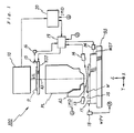
- Fig. 1 shows a schematic arrangement of an exposure apparatus 100 according to an embodiment of the present invention.
- This exposure apparatus 100 is a step-and-scan projection exposure apparatus.
- the exposure apparatus 100 comprises an illumination system 10, a reticle stage RST for holding a reticle R as a mask, a projection optical system PL, a wafer stage WST on which a wafer W as a substrate (object) is placed, an alignment microscope AS as an image pickup unit, a main control system 20 for systematically controlling the overall apparatus, and the like.
- the illumination system 10 includes a light source, an illuminance uniforming optical system comprising a fly-eye lens as an optical integrator, a relay lens, a variable ND filter, a reticle blind, a dichroic mirror, and the like (none of them are shown).
- a light source an illuminance uniforming optical system comprising a fly-eye lens as an optical integrator, a relay lens, a variable ND filter, a reticle blind, a dichroic mirror, and the like (none of them are shown).
- the arrangement of such illumination system is disclosed in, e.g., Japanese Patent Laid-Open No. 10-112433.
- a charged particle beam such as X-rays, electron rays, or the like may be used in place of light sent out from the aforementioned light source unit.
- Illumination light emitted by the light source unit enters the illuminance uniforming optical system when the shutter is open.
- a large number of secondary light sources are formed at the exit end of the illuminance uniforming optical system, and illumination light components sent out from a large number of secondary light sources reach the reticle blind.
- Illumination light transmitted through the reticle blind is output via an imaging lens system.
- This illumination system 10 illuminates slit-like illumination area portions, which are defined by the reticle blind, on the reticle R having circuit patterns and the like formed thereon with illumination light IL with nearly uniform illuminance.
- the reticle R is fixed on the reticle stage RST by, e.g., vacuum chucking.
- the reticle stage RST can be finely driven in the X-Y plane perpendicular to the optical axis (which coincides with an optical axis AX of the projection optical system PL, described later) of the illumination system and can be driven at a designated scan velocity in a predetermined scan direction (Y-direction in this case) by a reticle stage driver (not shown) comprising a magnetic float type two-dimensional linear actuator so as to align the reticle R.
- the magnetic float type two-dimensional linear actuator includes a Z-drive coil in addition to an X-drive coil, Y-drive coil, and the like, the reticle stage can also be finely driven in the Z-direction.
- the position of the reticle stage RST within a stage moving surface is always detected by a reticle laser interferometer (to be referred to as a "reticle interferometer” hereinafter) 16 via a movable mirror 15 at a resolution of around 0.5 to 1 nm.
- the position information of the reticle stage RST from the reticle interferometer 16 is sent to a stage control system 19, which drives the reticle stage RST via the reticle stage driver (not shown) on the basis of the position information of the reticle stage RST.
- the projection optical system PL is disposed below the reticle stage RST in Fig. 1, and the direction of its optical axis AX is defined as the Z-axis direction.
- the projection optical system PL for example, a refraction optical system which is both-side telecentric, and has a predetermined reduction ratio (e.g., 1/5, 1/4, or 1/6) is used. For this reason, when the illumination area of the reticle R is illuminated with illumination light IL coming from the illumination optical system, a reduced-scale image (partial inverted image) of the circuit pattern on the reticle R within that illumination area is formed on the wafer W, the surface of which is applied with a resist (photosensitive agent), via the projection optical system PL.
- the wafer stage WST is disposed on a base BS below the projection optical system PL in Fig. 1, and a wafer holder 25 is mounted on the wafer stage WST.
- the wafer W is fixed by, e.g., vacuum chucking or the like on the wafer holder 25.
- the wafer holder 25 can tilt in any direction with respect to a plane perpendicular to the optical axis of the projection optical system PL by a driver (not shown), and can also be finely movable in the direction of the optical axis (Z-direction) of the projection optical system PL.
- the wafer holder 25 is finely rotatable about the optical axis AX.
- Position information (or velocity information) WPV of the wafer stage WST is sent to the stage control system 19, which controls the wafer stage WST on the basis of this position information (or velocity information) WPV.
- the alignment microscope AS is an offaxis alignment detector disposed on the side surface of the projection optical system PL.
- This alignment microscope AS outputs image pickup results of alignment marks (wafer marks) contained in each shot area on the wafer W.
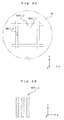
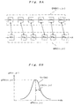
- alignment marks as the alignment marks, an X-position detection mark MX(i, j) and Y-position detection mark MY(i, j), which are formed on street lines around a shot area SA(i, j) on the wafer W, as shown in, e.g., Fig. 2A, are used.
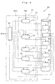
- the main control system 20 comprises a main control unit 30 and storage unit 40.
- the main control unit 30 comprises a control unit 39 which controls the operation of the exposure apparatus 100 by, e.g., supplying stage control data SCD to the stage control system 19 and serves as a set selection unit for selecting a sample set and replacement candidate set, and a position arithmetic unit 37.
- the aforementioned alignment microscope AS, control unit 39, and position arithmetic unit 37 constitute a position detector.
- the mark information arithmetic unit 32, parameter calculation unit 33, and valid value calculation unit 34 constitute an estimation calculation unit
- the estimation calculation unit and evaluation unit 35 constitute an evaluation arithmetic unit.
- the alignment microscope AS and picked-up image data acquisition unit 31 constitute a measurement unit.
- the parameter calculation unit 33 and valid value calculation unit 34 constitute a parameter determination unit.
- the flow of data is indicated by the solid arrows, and the flow of control is indicated by the dotted arrow. The respective operations of the units in the main control system 20 will be described later.
- the main control system 20 is constituted by combining various units.
- the main control system 20 may be constituted as a computer system, and the respective functions of the units that constitute the main control unit 30 may be implemented by programs installed in the computer.
- an oblique-incident-type multi-point focus detection system is fixed to a support portion (not shown) that supports the projection optical system PL, and comprises an illumination optical system 13 which directs imaging light beams used to form a plurality of slit images in an oblique direction with respect to the direction of the optical axis AX toward the best imaging surface of the projection optical system PL, and a light-receiving optical system 14 for receiving these imaging light beams reflected by the surface of the wafer W via slits.
- the stage control system 19 drives the wafer holder 25 in the Z-direction and an oblique direction on the basis of wafer position information from this multi-point focus detection system (13, 14).
- the arrangement coordinate position of each shot area on the wafer W is detected as follows.
- marks MX(i, j) and MY(i, j) are already formed on the wafer W in wafer processing up to the previous layer (e.g., in a process for the first layer).
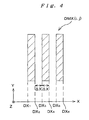
- the X-position DX x of the mark DMX(i, j) is defined by and is known.
- a Y-position DY X (i, j) of the mark DMX(i, j) is determined upon design, and is known.
- the Y-position DY x of the mark DMY(i, j) is defined by and is known. Furthermore, an X-position DX Y (i, j) of the mark DMY(i, j) is determined upon design, and is known.
- M marks MX (i pm , j pm ) and M marks MY(i ps , j ps ) as elements of each sample set S p are respectively selected not to line up upon design. Also, when comparing any two of the sample sets S p , each set includes at least one element that the other does not include.
- N marks MX(i qn , j qn ) and N marks MY(i qt , j qt ) as elements of each replacement candidate set Rq are also respectively selected not to line up upon design. Furthermore, when comparing any two of the replacement candidate sets Rq, each set includes at least one element that the other does not include.
- the numbers of marks MX(i pm , j pm ) and marks MY(i ps , j ps ) as elements of the sample set S p are equal to each other (M), but may be different from each other.
- each of the numbers of marks MX(i pm , j pm ) and marks MY(i ps , j ps ) as elements of the sample set S p must be three or more, and the total of them must be larger than 6.
- the numbers of marks MX(i qn , j qn ) and marks MY(i qt , j qt ) as elements of the replacement candidate set Rq are equal to each other (N), but may be different from each other.
- each of the numbers of marks MX(i qn , j qn ) and marks MY(i qt , j qt ) as elements of the replacement candidate set Rq must be three or more, and the total of them must be larger than 6.
- the first wafer W is loaded onto the wafer holder 25 by a wafer loader (not shown), and alignment with coarse accuracy (prealignment) is done by the main control system 20 moving the wafer via the stage control system 19 so that marks MX(i, j) and MY(i, j) are placed within the observation field of view of the alignment microscope AS.
- prealignment is done by the main control system 20 (more specifically, control unit 39) via the stage control system 19 on the basis of observation of the outer shape of the wafer W, the observation result of marks MX(i, j) and MY(i, j) in a broader field of view, and position information (or velocity information) from the wafer interferometer 18.
- the wafer W is moved to locate the first mark (X-position detection mark MX(i 11 , j 11 )) at the image pickup position of the alignment microscope AS in step 211 in Fig. 6. Such movement is done under the control of the main control system 20 via the stage control system 19.
- the alignment microscope AS picks up an image of the mark MX (i 11 , j 11 ) in step 212. Then, the picked-up image data acquisition unit 31 stores inputted picked-up image data IMD in the picked-up image data storage area 41 in accordance with an instruction from the control unit 39, thus acquiring picked-up image data IMD.
- the mark information calculation unit 32 reads out picked-up image data associated with the mark MX(i 11 , j 11 ) from the picked-up image data storage area 41, and extracts the X-positions of six edges as position information in the mark MX(i 11 , j 11 ) on the basis of the picked-up image data and position information (or velocity information) WPV from the wafer interferometer 18 in accordance with an instruction from the control unit 39.
- Such extraction of the X-positions of the edge can be implemented by analyzing a waveform obtained by scanning the picked-up image data along an XS(i 11 , j 11 ) axis which passes all the three line portions of the mark MX(i 11 , j 11 ) and is parallel to the X-axis, as shown in Fig. 7, or by analyzing a waveform obtained by integrating the picked-up image data in the Y-direction. Note that the latter method requires a larger arithmetic volume but can accurately extract the X-positions of the edges.
- FX (i 11 , j 11 ) DX x (i 11 , j 11 ) + dFX (i 11 , j 11 ) ⁇ (6A)
- the value dFX (i 11 , j 11 ) may be calculated by equation (7), and the X-position may be calculated by equation (6A) using this value in place of a calculation given by equation (5).
- Figs. 8A and 8B show an example wherein the X-position FX(i 11 , j 11 ) of the mark MX(i 11 , j 11 ) and its occurrence probability pFX(i 11 , j 11 ) are calculated on the basis of the measured edge positions FX k (i 11 , j 11 ), and Figs. 9A and 9B show another example.
- Fig. 8A illustrates the edge positions DX k (i 11 , j 11 ) as elements on the X-axis in the mark DMX (i 11 , j 11 ), and has symbols DX k attached onto those elements.
- Fig. 8A illustrates the edge positions FX k (i 11 , j 11 ) as elements on the X-axis in the mark MX(i 11 , j 11 ), and has symbols FX k attached onto those elements.
- the probability density function f X11 (dx) of the error distribution is steep, as shown in Fig. 8B. That is, the standard deviation ⁇ X(i 11 , j 11 ) is small.
- the probability density function f X11 (dx) of the error distribution is gradual, as shown in Fig. 9B. That is, the standard deviation ⁇ X(i 11 , j 11 ) of the error distribution takes a large value.
- the probability density pFX(i 11 , j 11 ) that an error takes the value dFX(i 11 , j 11 ), i.e., the X-position of the mark XM(i 11 , j 11 ) assumes the value FX(i 11 , j 11 ) becomes smaller than that in Fig. 8B mentioned above.
- step 215 it is checked in step 215 if mark information calculations for all the selected marks are complete.
- the answer in step 215 is NO, and the sequence advances to step 216.
- step 216 the control unit 39 moves the wafer W to a position where the next mark falls within the image pickup field of view of the alignment microscope AS.
- Such movement of the wafer W is done by moving the wafer stage WST when the control unit 39 controls the wafer drive unit 24 via the stage control system 19 on the basis of the prealignment result.
- the X-positions FX(i pm , j pm ) of other marks MX(i pm , j pm ) and their probability densities pFX(i pm , j pm ), the Y-positions FY(i ps , j ps ) of marks MY(i ps , j ps ) and their probability densities pFY(i ps , j ps ), the X-positions FX(i qn , j qn ) of marks MX(i qn , j qn ) and their probability densities pFX(i qn , j qn ), and the Y-positions FY(i qt , j qt ) of marks MY(i qt , j qt ) and their probability densities pFY(i qt , j qt ) are computed in the same manner as
- the parameter calculation unit 33 then calculates the estimations of parameters which uniquely specify the arrangement of shot areas SA(i, j).
- the marks MX(i, j) and MY(i, j) formed on the wafer W deviate from their ideal positions due to a mismatch between a stage coordinate system (X, Y) which specifies the position of the wafer stage WST, and the arrangement coordinate system of shot areas as a design coordinate system, i.e., a wafer coordinate system ( ⁇ , ⁇ ), and such a mismatch occurs due to the following four main factors.
- a pattern to be transferred to a target position (DX, DY), in terms of design, on the wafer coordinate system ( ⁇ , ⁇ ) is transferred to a position (EX, EY) on the stage coordinate system (X, Y), of which the position is given by Note that various other error factors are also present in addition to the aforementioned ones upon actual transfer, and the position (EX, EY) is considered as an expected transfer position.
- the target transfer position (DX, DY) and expected transfer position (EX, EY) are related by which expresses a first-order approximation of the trigonometric function in equation (11).
- the parameter calculation unit 33 calculates an expected transfer X-position EX(i pm , j pm ) of each mark MX(i pm , j pm ) from the ideal transfer position (DX X (i pm , j pm ), DY X (i pm , j pm )) of the mark MX(i pm , j pm ) using equation (13), the EX(i pm , j pm ) containing the parameters.
- the parameter calculation unit 33 calculates an expected transfer Y-position EY(i ps , j ps ) of each mark MY(i ps , j ps ) from the ideal transfer position (DX Y (i ps , j ps ), DY Y (i ps , j ps )) of the mark MY(i ps , j ps ) using equation (13), the EY(i ps , j ps ) containing the parameters.
- the mark position is more reliable as it is calculated from the measurement results of the edge positions of the mark having a shape more identical to the ideal mark's shape. Also, the reliability level of the calculated mark position depends on the occurrence probability of the mark position, i.e., the probability density.
- the parameter calculation unit 33 then calculates the estimations of the six parameters A 11 , A 12 , A 21 , A 22 , O X , and O Y which minimize a variation S p given by by applying the method of least squares on the basis of the evaluated errors ⁇ X pm and ⁇ Y ps .
- the parameter calculation unit 33 calculates estimations A 11p , A 12p , A 21p , A 22p , O Xp , and O Yp of the six parameters A 11 , A 12 , A 21 , A 22 , O X , and O Y by solving simultaneous equations made up of six equations obtained by setting partial differentials of the variation S P given by equation (22) by the six parameters A 11 , A 12 , A 21 , A 22 , O X , and O Y to zero.
- the parameter calculation unit 33 stores P groups of estimations (A 11p , A 12p , A 21p , A 22p , O Xp , O Yp ) calculated in this way in the estimation storage area 45.
- the valid value calculation unit 34 reads out the P sets of calculated estimations (A 11p , A 12p , A 21p , A 22p , O Xp , G Yp ) from the estimation storage area 45, and calculates an X-position deviation ⁇ p X, Y-position deviation ⁇ p Y, and covariance ⁇ p XY associated with each sample set S p upon adopting each group of estimations as follows.
- the valid value calculation unit 34 calculates an X-position deviation ⁇ p X, Y-position deviation ⁇ p Y, and covariance ⁇ p XY respectively by
- the calculated deviations ⁇ p indicate the certainties of the respective estimations (A 11p , A 12p , A 21p , A 22p , O Xp , O Yp ), i.e., the degrees by which the respective sample sets S p represent the entire marks MX and MY.
- the parameter calculation unit 33 checks in step 204 if there are a plurality of sample sets S p . In the above, since the number of sample sets S p is P (> 1), the answer in step 204 is YES, and the sequence advances to step 205.
- step 205 on the basis of the P groups of estimations (A 11p , A 12p , A 21p , A 22p , O Xp , O Yp ) and deviations ⁇ p that reflect the certainty, the valid value calculation unit 34 calculates weighted mean of each parameter of the estimations (A 11p , A 12p , A 21p , A 22p , O Xp , O Yp ) using the values (1/ ⁇ p ) as respective weight coefficients of the estimations, and obtains a set of statistically valid parameter values (A 110 , A 120 , A 210 , A 220 , O Xo , O Yo ). That is, the valid value calculation unit 34 computes
- the valid value calculation unit 34 calculates deviation ⁇ o upon adopting the statistically valid parameter values (A 110 , A 120 , A 210 , A 220 , O Xo , O Yo ) by
- the valid value calculation unit 34 stores the statistically valid parameter values (A 110 , A 120 , A 210 , A 220 , O XO , O YO ) and deviation ⁇ o calculated in this way in the valid value storage area 44 as parameter values (AU 11 , AU 12 , AU 21 , AU 22 , OU X , OU Y ) and deviation ⁇ U used upon exposure of the wafer W.
- the evaluation unit 35 calculates a estimation (A 11q , A 12q , A 21q , A 22q , O Xq , and O Yq ) for parameters A 11 , A 12 , A 21 , A 22 , O X , and O Y which uniquely specify the arrangement of shot areas SA(i, j) in the same manner as in the case of the sample sets S p .
- the evaluation device 35 calculates X-position deviations ⁇ q X, Y-position deviations ⁇ q Y, and covariances ⁇ q XY of respective replacement candidate sets Rq upon adopting the Q sets of calculated estimations (A 11q , A 12q , A 21q , A 22q , O Xq , O Yq ), and also deviations ⁇ q upon adopting the Q sets of calculated estimations (A 11q , A 12q , A 21q , A 22q , O Xq , O Yq ) in the same manner as in the case of the sample sets S p .
- the evaluation unit 35 reads out the statistically valid parameter values (AU 11 , AU 12 , AU 21 , AU 22 , OU X , OU Y ) and deviation ⁇ U from the valid value storage area 44, and evaluates similarities with the estimations (A 11q , A 12q , A 21q , A 22q , O Xq , O Yq ) and deviations ⁇ q associated with the replacement candidate sets Rq.
- the evaluation unit 35 checks in step 223 if there is a replacement candidate set Rq that has been found to be similar as a result of evaluation in step 222. If NO in step 223, the evaluation unit 35 sends a report indicating this to the control unit 39.
- the control unit 39 receives the report and selects new Q replacement candidate sets, and stores them in the sample set information storage area 42 in step 225. In this fashion, the process of subroutine 207 executed if NO in step 223 ends.
- the evaluation unit 35 replaces the replacement candidate set information in the sample set information storage area 42 by information that pertains to only the replacement candidate set or sets found to be similar.
- the evaluation unit 35 checks in step 226 if there is a replacement candidate set that is successively found to be similar a predetermined number of times. For example, when the predetermined number of times is three, since similarity evaluation has been done only once for only one wafer, the answer in step 226 is NO, and then the process of subroutine 207 ends.
- step 226 If the predetermined number of times is one, the answer in step 226 is YES, and the evaluation unit 35 selects a replacement candidate set having the highest similarity from those found to be similar as a new sample set, and replaces the sample set information in the sample set information storage area 42 by information that pertains to the new sample set in step S227, thus ending the process of subroutine 207.
- the number of sample sets is one from here on.
- control unit 39 calculates the arrangement coordinate positions of shot areas SA(i, j) using the parameter values (AU 11 , AU 12 , AU 21 , AU 22 , OU X , OU Y ) calculated in step 205 in Fig. 5.
- the reticle R and wafer W are aligned on the basis of the calculated shot area arrangement under the control of the control unit 39, and the wafer W and reticle R are synchronously moved at a velocity ratio corresponding to the projection magnification in opposite directions along the scan direction (Y-direction) while a slit-like illumination area (the center of which nearly coincides with the optical axis AX) is illuminated with illumination light IL, thus transferring a pattern on a pattern area of the reticle R onto each shot area SA(i, j) in the reduced scale.
- the wafer is unloaded under the control of the control unit 39.
- step 208 in Fig. 5 if exposure of all wafers (e.g., wafers for one lot) is complete. In the above process, since exposure of only the first wafer is complete, the answer in step 208 is NO.
- the next wafer is loaded onto the wafer holder 25 by the wafer loader (not shown) in the same manner as the first wafer, and alignment with coarse accuracy (prealignment) is done by the main control system 20 moving the wafer W via the stage control system 19 so that marks MX(i, j) and MY(i, j) can be placed within the observation field of view of the alignment microscope AS. After that, steps 202 to 207 in Fig. 5 are repeated for each wafer W in the same manner as the first wafer until YES is determined n step 208.
- step 208 in Fig. 5 If it is determined in step 208 in Fig. 5 that exposure of all wafers is complete, the exposure process ends.
- step 226 in Fig. 10 If replacement candidate sets which are successively determined first to be similar to the sample set a predetermined number of times are found in step 226 in Fig. 10, since the most similar one of those sets is used as the subsequent sample set, the number of sample sets becomes one. As a result, NO is determined in step 204 in Fig. 5 executed thereafter, and step 206 is executed in place of step 205 mentioned above. That is, the estimations of position parameters calculated based on the position measurement results of marks MX and MY contained in the single sample set are directly adopted as parameter values (AU 11 , AU 12 , AU 21 , AU 22 , OU X , OU Y ) used upon exposure of the wafer W.
- a plurality of sample sets are selected initially, and position parameters are calculated based on the result of estimating the position distribution of the entire marks MX and MY according to respective groups of the estimations and their certainties of position parameters calculated for the sample sets. Accordingly, statistically valid position parameter values can be obtained. Therefore, the wafer W can be aligned very accurately, and the pattern transfer accuracy can be improved.
- the appropriate set is used as a new sample set. Therefore, since the time required for aligning a wafer W can be shortened while maintaining statistical validity of the obtained position parameters, the throughput can be improved.
- a mark position is calculated on the basis of the position information of each position measurement mark (alignment mark) obtained through measuring the alignment marks associated with each sample set, i.e., the measurement results of a plurality of edge positions of each alignment mark; the certainty of that mark position is calculated from the design values of the edge positions and errors, and parameter values (estimations) that uniquely specify the arrangement of shot areas (i, j) on the wafer W are calculated for each sample set using the certainty as the weight. Therefore, because the arrangement of the shot areas (i, j) on the wafer W is calculated using the finally obtained accurate parameter values to align the wafer W, accurate alignment can be performed, and pattern transfer with high overlap accuracy can be achieved.
- Fig. 11 is a flow chart of production of devices (semiconductor chips such as IC or LSI, liquid crystal panels, CCD's, thin-film magnetic heads, micro machines, or the like) in this embodiment.
- step 301 design step
- step 302 mask fabrication step
- step 303 wafer preparation step
- a wafer is prepared using material such as silicon and the like.
- step 304 wafer process step
- step 305 device assembly step
- steps 304 and 305 devices are assembled using the wafer processed in step 304.
- This step 305 includes processes such as an assembly process (dicing, bonding), packaging step (chip encapsulation), and the like.
- step 306 inspection step
- inspections such as an operation confirmation test, durability test, and the like of the devices manufactured in step 305 are performed. After these steps, the process is complete, and the devices are shipped out.
- Fig. 12 shows a detailed, exemplary flow of step 304 for manufacturing semiconductor devices.
- the wafer surface is oxidized in step 311 (oxidation step).
- step 312 CVD step
- step 313 electrode formation step
- step 314 ion implantation step
- ions are implanted into the wafer. Steps 311 to 314 mentioned above constitute a pre-process of each step in the wafer process, and is selectively executed in accordance with the process required in each step.
- a post-process steps is performed as follows.
- the wafer is coated with a photosensitive agent in step 315 (resist formation step), and the above exposure apparatus transfers the circuit pattern on the mask onto the wafer aligned using the aforementioned scheme, in step 316 (exposure step).
- the exposed wafer is developed in step 317 (development step), and an exposing member of portions other than portions where the resist remains is removed by etching in step 318 (etching step). Then, the resist that has become unnecessary after etching is removed in step 319 (resist removal step).
- multi-layer circuit patterns are formed on the wafer.
- one edge position is extracted for each edge using the picked-up image data on a single axis parallel to the direction of the mark pattern change or the integrated data in the direction perpendicular to the direction of the mark pattern change, as described above.
- an average value dFX(i pm , j pm ) and standard deviation ⁇ X (i pm , j pm ) of the errors dFX kh (i pm , j pm ) are respectively calculated by
- the X-position FX(i pm , j pm ) and standard deviation ⁇ X(i pm , j pm ) of the mark MX(i pm , j pm ) calculated in this way are statistically more valid than those in the aforementioned embodiment, since the number of extracted edge positions is larger than that in the above embodiment.
- the Y-position FY(i ps , j ps ) of each mark MY(i ps , j ps ) can be calculated in the same manner as the mark MX(i pm , j pm ).
- the calculated Y position FY(i ps , j ps ) and standard deviation ⁇ Y(i ps , j ps ) of the mark MY(i ps , j ps ) are statistically more valid than those in the above embodiment, since the number of extracted edge positions is larger than that in the above embodiment.
- Rotation of shot region This is caused when a reticle R has rotated with respect to the stage coordinate system (X, Y) upon transferring a pattern formed on the reticle R onto a wafer W or when yawing is accidentally mixed in the movement of a wafer stage WST upon scanning exposure, and is expressed by a rotation error ⁇ of the wafer coordinate system ( ⁇ , ⁇ ) with respect to a shot coordinate system having coordinate axes parallel to the ⁇ - and ⁇ -axes.
- Orthogonality of shot region This is caused by distortion of a pattern formed on a reticle R, distortion (distortion error) of a projection optical system PL, and the like, and is expressed by an orthogonality error ⁇ .
- Linear expansion/shrinkage of shot region This is caused by an error of the projection magnification upon projecting a pattern formed on a reticle R onto a wafer W or by the wafer entirely or partially expanding or shrinking due to a formation process or the like.
- This expansion/shrinkage amount is expressed by wafer scaling values r X and r Y in the coordinate axis directions (i.e., ⁇ - and ⁇ -directions) of the shot coordinate system.
- the wafer scaling value r X in the ⁇ -direction is represented by the ratio between the actually measured value and design value of the distance between two points in the ⁇ -direction on the wafer W
- the wafer scaling value r Y in the ⁇ -direction is represented by the ratio between the actually measured value and design value of the distance between two points in the ⁇ -direction.
- the designed transfer position (DX, DY) and expected transfer position (EX, EY) are related by which expresses a first-order approximation of the trigonometric function in equation (49).
- parameters which uniquely specify the arrangement of shot areas SA(i, j) are ten parameters A 11 , A 12 , A 21 , A 22 , B 11 , B 12 , B 21 , B 22 , O X , and O Y .
- the number of wafer marks is not limited to four, and can be three or more.
- the two-dimensional marks WMp marks having patterns shown in, e.g., Figs. 15A to 15D, can be used.
- optimal values of the error factors (r X , r Y , ⁇ , ⁇ ) are calculated using equations (32) to (35) for the aforementioned controllable error factors (r X , r Y , ⁇ , ⁇ ) and four parameters (B 11 , B 12 , B 21 , B 22 ) of the ten parameters, the optimal values of which have been calculated, and in accordance with those error factors, corrected are the magnification of the projection optical system PL, the synchronous velocity ratio upon scanning exposure, synchronous moving directions upon scanning exposure, and the like.
- the accuracy of superposition is further improved.
- a plurality of initial sample sets are used, but if one sample set from which accurate position parameters can be calculated is known, that sample set may be used as only one initial sample set. Even in such a case, the processing flow of the above embodiment can be applied. Since the number of sample sets is one from the beginning, in the processing flow of the above embodiment, the answer in step 204 is always NO.
- whether or not it is possible to reduce the number of elements of a sample set is evaluated by comparing the position parameter values and their certainties calculated from the sample set, and estimations of position parameters and their certainties calculated from each of a plurality of replacement candidate sets.
- evaluation can be performed by so-called cross-verification.
- the position errors of marks MX and MY included in a sample set are calculated using the estimations of the position parameters calculated for each replacement candidate set, and the position error distribution of the marks MX and MY included in the sample set is calculated based on that calculation result, thus evaluating if each replacement candidate set has statistical characteristics equivalent to that of the sample set.
- replacement possibility can be evaluated without calculating the position parameter values and their certainties from the sample set.
- Such cross-verification is particularly effective when the replacement candidate set is a subset of the sample set.
- a plurality of initial sample sets are replaced by one new sample set.
- the number of elements of each of the plurality of initial sample sets may be reduced.
- a new sample set is searched for that has characteristics equivalent thereto in the statistical characteristics of position errors of marks and consists of fewer elements.
- one-dimensional marks MX and MY are used.
- two-dimensional marks shown in Figs. 15A to 15D may be used.
- one-dimensional marks MX and MY may be used.
- a box-in-box mark may be used in addition to those shown in Figs. 15A to 15D.
- the aforementioned one-dimensional position detection process may be performed twice, or two-dimensional template matching into which the above one-dimensional template matching for one-dimensional signals is extended may be performed on two-dimensional signal waveforms of two-dimensional marks.
- the off-axis alignment method that measures the positions of alignment marks on a wafer without the intervention of a projection optical system is adopted.
- a TTL (through-the-lens) scheme that measures the positions of alignment marks on a wafer via a projection optical system, or a TTR (through-the-reticle) that simultaneously observes a wafer and reticle via a projection optical system may be adopted.
- sample alignment upon observation, sample alignment senses the position of a wafer mark where the deviation between a reticle mark formed on the reticle and a wafer mark formed on the wafer is zero.
- the coordinate positions of the shot areas are calculated.
- the step pitch of each shot may be calculated.
- the fly-eye lens is used as an optical integrator (homogenizer).
- a rod integrator may be used.
- the rod integrator is disposed such that its exit surface is nearly conjugated with the pattern surface of a reticle R.
- Such an illumination optical system using the rod integrator is disclosed in, e.g., U.S. Patent No. 5,675,401, and the disclosures in the above U.S. Patent is incorporated herein by reference as long as the national laws in designated states or elected states, to which this international application is applied, permit.
- the fly-eye lens and rod integrator may be combined, or two fly-eye lenses or rod integrators may be disposed in series to build double optical integrators.
- the present invention is applied to the step-and-scan scanning exposure apparatus.
- the application range of the present invention is not limited to such specific apparatus, and the present invention can be suitably applied to a stationary exposure apparatus such as a stepper or the like.
- an exposure apparatus using, e.g., ultraviolet rays may adopt as a projection optical system a reflection system consisting of reflective optical elements alone or a reflection/refraction system (a catadioptric system) having both reflective and refractive optical elements.
- a reflection/refraction system which is disclosed in, e.g., Japanese Patent Laid-Open No. 8-171054 and corresponding U.S. Patent No. 5,668,672, Japanese Patent Laid-Open No. 10-20195 and corresponding U.S. Patent No. 5,835,275, and the like, and has a beam splitter and concave mirror as reflection optical elements, or a reflection/refraction system which is disclosed in Japanese Patent Laid-Open No.
- a reflection/refraction system which comprises a plurality of refraction optical elements and two mirrors (a main mirror being a concave mirror and a sub-mirror that is a back surface mirror of which the reflection surface is formed on the opposite side to the incident surface of a refraction element or plane parallel plate) that are disposed along one axis, and has the intermediate image, formed by those refraction optical elements, of a reticle pattern again imaged on a wafer using the main mirror and sub-mirror, the reflection/refraction system being disclosed in Japanese Patent Laid-Open No. 10-104513 and U.S. Patent No. 5,488,229 corresponding thereto.
- the main mirror and sub-mirror are disposed in series with the plurality of refraction optical elements, and an illumination light passes through a portion of the main mirror, is reflected by the sub-mirror and the main mirror in turn, passes through a portion of the sub-mirror and reaches the wafer.
- the reflection/refraction-type projection optical system a reduction system may be employed which has, e.g., a circular image field, is telecentric on both the object plane side and image plane side, and has a reduction ratio of, e.g., 1/4 or 1/5.
- the illumination area of the illumination light may be a rectangular-slit-shaped area whose center almost coincides with the optical axis of the projection optical system and which extends along a direction almost perpendicular to the scanning direction of a reticle or wafer.
- a vacuum ultraviolet light ArF excimer laser light or F 2 laser light is used.
- a higher harmonic wave may be used which is obtained with wavelength conversion into ultraviolet by using nonlinear optical crystal after having amplified a single wavelength laser light, infrared or visible, emitted from a DFB semiconductor laser device or a fiber laser by a fiber amplifier having, for example, erbium (or erbium and ytterbium) doped.
- an eight-time-higher harmonic wave of which the wavelength is in the range of 189 to 199nm or a ten-time-higher harmonic wave of which the wavelength is in the range of 151 to 159nm is emitted.
- a seven-time-higher harmonic wave of which the wavelength is in the range of 147 to 160nm is emitted, and, especially, when the oscillation wavelength is in the range of 1.099 to 1.106um, a seven-time-higher harmonic wave of which the wavelength is in the range of 157 to 158nm, that is, almost the same as F 2 laser light (ultraviolet light) is obtained.
- F 2 laser light ultraviolet light
- ytterbium-doped fiber laser can be employed as the single wavelength laser.
- the present invention can be applied not only to an exposure apparatus for producing micro devices such as semiconductor devices but also to an exposure apparatus that transfers a circuit pattern onto a glass substrate or silicon wafer so as to produce reticles or masks used by a light exposure apparatus, EUV (Extreme Ultraviolet) exposure apparatus, X-ray exposure apparatus, electron beam exposure apparatus, etc.
- EUV Extreme Ultraviolet
- X-ray exposure apparatus X-ray exposure apparatus
- electron beam exposure apparatus etc.
- a transmission-type reticle is employed in general.
- quartz glass, quartz glass with fluorine doped, fluorite, magnesium fluoride, or quartz crystal is employed as the substrate of the reticle.
- an X-ray exposure apparatus of a proximity method or electron beam exposure apparatus employs a transmission-type mask (stencil-mask, membrane-mask); an EUV exposure apparatus employs a reflection-type mask, and as the substrate of the mask, silicon wafer or the like is employed.
- a transmission-type mask stencil-mask, membrane-mask
- EUV exposure apparatus employs a reflection-type mask, and as the substrate of the mask, silicon wafer or the like is employed.
- the present invention can be applied not only to a wafer exposure apparatus used in the production of semiconductor devices but also to an exposure apparatus that transfers a device pattern onto a glass plate and is used in the production of displays such as liquid crystal display devices and plasma displays, an exposure apparatus that transfers a device pattern onto a ceramic plate and is used in the production of thin magnetic heads, and an exposure apparatus used in the production of pick-up devices (CCD, etc.).
- an exposure apparatus that transfers a device pattern onto a glass plate and is used in the production of displays such as liquid crystal display devices and plasma displays
- an exposure apparatus that transfers a device pattern onto a ceramic plate and is used in the production of thin magnetic heads and an exposure apparatus used in the production of pick-up devices (CCD, etc.
- CCD pick-up devices
- positional detection and alignment according to the present invention can be applied to positional detection of the alignment marks on a reticle and alignment of the reticle, and also to other units than exposure apparatuses such as a unit to observe objects and a unit that is used to detect positions of objects and align them in an assembly line, process line or inspection line.
- the position detection method and position detection apparatus of the present invention since a statistical process is executed on the basis of position information of position detection points obtained by measurement of the position detection points on an object, position information of any area on the object is accurately and efficiently detected. Therefore, the position detection method and position detection apparatus of the present invention are suitable for detecting the position of any area on an object.
- the positions of a predetermined number of alignment marks formed on a substrate are detected using the position detection method of the present invention, and a predetermined pattern is transferred onto divided areas while aligning the substrate on the basis of the detection result. Therefore, the exposing method and exposure apparatus of the present invention are suitable to perform multi-exposure for forming a multi-layer pattern with improved accuracy of superposition between layers. For this reason, the exposing method and exposure apparatus of the present invention are suitable for mass-production of devices having a fine pattern.
Landscapes
- Physics & Mathematics (AREA)
- General Physics & Mathematics (AREA)
- Engineering & Computer Science (AREA)
- Signal Processing (AREA)
- Exposure Of Semiconductors, Excluding Electron Or Ion Beam Exposure (AREA)
- Exposure And Positioning Against Photoresist Photosensitive Materials (AREA)
Abstract
A parameter calculation unit (33) statistically
calculates the estimations and their certainty of a
predetermined number of parameters, which uniquely
specify any position on an object, for each of a
plurality of measured sample sets on the basis of
position information of marks composing the sample set.
A valid value calculation unit (34) calculates
statistically valid values of the predetermined number of
parameters on the basis of groups of the estimations and
their certainty of the predetermined number of parameters
for the respective sample sets. Furthermore, an
evaluation unit (35) statistically evaluates if the
number of marks composing a sample set can be reduced.
If it is determined that the number of marks can be
reduced, the parameter calculation unit (33) calculates
values of the predetermined number of parameters by using
a new sample set having reduced number of marks. Using
the values of the predetermined number of parameters
calculated in this manner, the position of any area on
the object can be accurately detected.
Description
The present invention relates to a position
detection method and position detector, an exposure
method and exposure apparatus, and a device and device
manufacturing method and, more particularly, to a
position detection method and position detector for
obtaining arrangement information of divided areas on an
object, an exposure method and exposure apparatus using
the position detection method, and a device manufactured
using the exposure method and a manufacturing method
thereof.
In a lithography process for making semiconductor
devices, liquid crystal display devices, and the like, an
exposure apparatus which transfers a pattern formed on a
mask or reticle (to be generally referred to as a
"reticle" hereinafter) onto a substrate (to be referred
to as a "sensitive substrate or wafer" as needed
hereinafter) such as a wafer, glass plate, or the like
coated with a resist or the like via a projection optical
system is used. As such an exposure apparatus,
stationary exposure type projection exposure apparatus
such as a so-called stepper, or a scanning exposure type
projection exposure apparatus such as a so-called
scanning stepper is mainly used.
In these exposure apparatuses, position adjustment
(alignment) between a reticle and wafer must be
accurately performed prior to exposure. To achieve this
alignment, position detection marks (alignment marks) are
formed (transferred by exposure) in the previous
lithography process on the wafer in each of shot regions,
and the position of the wafer (or a circuit pattern on
the wafer) can be detected by detecting the positions of
the alignment marks. Alignment is performed on the basis
of the detection results of the positions of the wafer
(or a circuit pattern on the wafer).
Such alignment schemes include a die-by-die scheme
for performing alignment by detecting alignment marks in
each shot, and an enhanced global alignment (to be
abbreviated as "EGA" hereinafter) scheme for, after
measuring alignment marks (position adjustment marks
transferred together with a circuit pattern) at several
positions in a wafer, computing arrangement coordinate
positions of each shot area by a statistical scheme such
as a least square approximation and, upon exposure,
stepping a wafer using the accuracy of a wafer stage and
the computation result. This EGA scheme is disclosed in,
e.g., Japanese Patent Laid-Open No. 61-44429 and
corresponding U.S. Patent No. 4,780,617. Of these
schemes, the EGA scheme is prevalently used nowadays in
terms of the throughput of the apparatus.
In this EGA scheme, in order to determine a
plurality of parameters that uniquely specifies the
actual arrangement coordinate positions of shot areas
relative to ideal arrangement coordinate positions in
terms of design, more positions of alignment marks than
the minimum number of those required to obtain the
plurality of parameters are measured. Then,
statistically valid parameter values are determined using
a statistical scheme such as a least square approximation.
Upon applying such statistical scheme, error
analysis is performed under the premise that "all
position measurement results of alignment marks have the
same reliability" (hereafter, this case is referred to as
"prior art 1").
Also, as disclosed in Japanese Patent Publication
No. 7-120621, a technique for determining the
predetermined parameters by executing a fuzzy process
based on fuzzy inference using statistical values such as
the average value and variance of the measured positions
of the alignment marks and obtaining the arrangement
coordinate positions of the shot areas has also been
proposed (hereafter, this case is referred to as "prior
art 2").
When all alignment marks are equally formed, the
premise of prior art 1 that "all position measurement
results of alignment marks have the same reliability" is
true, but not true when the shapes of alignment marks
differ depending on their positions on a substrate.
Therefore, when the shapes of alignment marks differ
depending on their positions on a substrate, all position
measurement results, whether their reliabilities are high
or low, equally contribute to determination of the
arrangement coordinate positions of shot areas their
different reliabilities.
The accuracy of the arrangement coordinate position
determination of shot areas determined under the above
premise suffices to achieve conventionally required
exposure accuracy, but does not suffice for the increase
of integration degree in recent years.
Prior art 2 is free from any problem of the accuracy
of the arrangement coordinate position determination of
shot areas unlike in prior art 1. However, since prior
art 2 requires a huge computation volume for fuzzy
inference, a long period of time is required to determine
the arrangement coordinate positions of shot regions, and
this makes it difficult to improve the throughput of
exposure. In order to prevent such low throughput, a
large-scale computation resource is needed. However, the
use thereof causes the whole exposure apparatus to be
large and complicated.
Upon applying the conventional statistical scheme,
the positions of alignment marks to be measured on a
wafer are determined empirically or on a trial-and-error
basis that after transferring a pattern onto a wafer
while aligning the wafer using a temporarily selected
sample set, the same patterns on the wafer are measured,
and that if desired results are not obtained, another
sample set is selected.
As described above, in the conventional method, a
sample set of alignment marks as a subset of a set of all
alignment marks is determined by an aleatory method, and
the validity of determination of that sample set is not
quantitatively evaluated. Therefore, it is not
guaranteed that the error distribution of the positions
of a plurality of alignment marks as elements of a sample
set determined by the conventional method appropriately
reflects the error distribution of positions of all
alignment marks.
For trying to solve this problem, there is the
following method: the position control using a plurality
of parameters which are obtained using a provisional
sample set determined empirically or arbitrarily and
uniquely specify the arrangement coordinate positions of
shot regions, when the sample set includes shot areas
(so-called "isolated shots") having much larger alignment
errors than those of other shot regions, alignment marks
contained in such isolated shots are excluded from the
sample set. This method presupposes that only few
isolated shots exist, and that those alignment marks
cause the decrease of alignment accuracy for all shot
regions.
However, if alignment marks of two isolated shot
regions, of which pattern shift directions are almost
opposite to each other (i.e., the two shot areas having
negative correlation), are selected, high-accuracy
alignment is possible. Therefore, exclusion of the
measured position information of alignment marks
contained in an isolated shot area may result in an
alignment accuracy decrease.
In the case where a wafer is aligned on the basis of
the position measurement results of alignment marks
included in a subset (sample set) selected from a large
number of alignment marks, upon examining the validity of
a method for selecting the desired sample set, evaluating
separately individual alignment marks in the sample set
does not have much sense. This is because it is ideal
that the sample set broadly reflects the entire set and
because it is preferable that alignment marks in the
sample set preferably have a position distribution that
corresponds to that of alignment marks in the entire set.
For example, in the case where one of five alignment
marks in a sample set is an alignment mark contained in
an isolated shot region, if one fifth of all the
alignment marks are contained in isolated shot regions,
the sample set is more valid than a sample set excluding
alignment marks of isolated shot regions. That is,
position errors of measured alignment marks reflect the
position distribution of all the alignment marks somehow,
and should not be carelessly ignored. However, there
have been no proposals concerning a method for selecting
a sample set from the entire set of alignment marks
formed on a substrate so as to perform statistically
valid position control and alignment on the basis of the
position measurement results of alignment marks in the
sample set.
Furthermore, although it is not appropriate to
exclude alignment marks in descending order of position
error amounts in order to reduce the number of sample
alignment marks and alignment measurement time, there
have been no proposals concerning a method for reducing
the number of sample alignment marks while maintaining
alignment accuracy.
That is, an alignment technology that can meet
recent requirements of improved exposure accuracy and
throughput is needed.
The present invention has been made considering the
above situation, and a first object of the present
invention is to provide a position detection method and
position detector which can accurately and efficiently
detect arrangement information of divided areas on an
object.
A second object of the present invention is to
provide an exposure method and exposure apparatus that
can transfer a predetermined pattern onto a substrate
with high accuracy.
A third object of the present invention is to
provide a device on which fine patterns are accurately
formed.
A fourth object of the present invention is to
provide a manufacturing method of manufacturing a device
on which fine patterns are accurately formed.
According to the first aspect, there is provided a
first position detection method for detecting position
information of any area on an object provided with a
plurality of position-measurement-points, the position
detection method comprising a measurement step of
selecting more position-measurement-points than a minimum
number of measurements required to calculate values of a
predetermined number of parameters, which uniquely
specify position information of any area on the object,
from the plurality of position-measurement-points and
measuring pieces of position information of the
respective selected position-measurement-points; an
estimation step of calculating respective positions of
the selected position-measurement-points, based on the
measurement results of the pieces of position information,
and estimating probability density functions which each
represent occurrence probability of the calculated
position for respective one of the selected position-measurement-points;
a probability density calculation
step of calculating probability density of the calculated
position of each of the position-measurement-points,
based on respective one of the probability density
functions; and a parameter calculation step of evaluating
an error of each calculated position relative to
respective reference position while using the respective
calculated probability density's value as a piece of
weight information and calculating values of the
predetermined number of parameters, based on the
evaluated errors.
According to this method, pieces of position
information of selected position-measurement-points are
measured, and the positions and probability densities of
the selected position-measurement-points are calculated
on the basis of the measurement results. Upon
calculating the statistically most valid values of a
predetermined number of parameters, which uniquely
specify position information of any area on an object,
while using the calculated probability densities as
pieces of information each representing the certainty of
the position of a respective position-measurement-point,
the error between each calculated position and a
respective reference position is weighted in accordance
with the certainty of the calculated position of the
respective position-measurement-point, i.e., the
probability density at the calculated position of the
respective position-measurement-point. That is, if the
probability density is large, the weight is large, and if
the probability density is small, the weight is small.
As a result, when the calculated position of a position-measurement-point
has high certainty, the degree of
influence of the error of the calculated position of the
position-measurement-point relative to its reference
position is high; when the calculated position of a
position-measurement-point has low certainty, the degree
of influence of the error of the calculated position of
the position-measurement-point relative to its reference
position is low. Therefore, since statistically valid
values of a predetermined number of parameters which
uniquely specify position information of any area on an
object can be calculated while rationally reflecting
respective certainties of the calculated positions of
position-measurement-points, the position of a area of
interest on the object can be accurately detected.
In the first position detection method of the
present invention, the reference positions can be
determined in advance on the basis of design information.
The probability density of each calculated mark (a
position-measurement-point) position directly reflects
the certainty of a respective mark position. Therefore,
in the first position detection method of the present
invention, the errors are evaluated by multiplying the
errors of the calculated positions relative to the
respective reference positions by the respective
probability densities of the calculated positions.
In the first position detection method of the
present invention, normal distributions can be adopted as
the probability density functions. In this way, it is
particularly valid to presume the occurrence probability
distributions to be a normal distribution when variations
of errors of the calculated mark positions relative to
the respective reference positions are expected to be
random like normal random numbers. When the occurrence
probability distribution is known, a probability density
function of that probability distribution can be used
instead of a normal distribution. On the other hand,
when the occurrence probability distribution is unknown,
it is rational to presume the occurrence probability
distribution to be a normal distribution, which is the
most general probability distribution.
In the first position detection method of the
present invention, position measurement marks can be
formed at the position-measurement-points. In such case,
the position of each position-measurement-point can be
measured by detecting a respective position measurement
mark. Note that the position measurement mark can be,
e.g., a line-and-space mark, box-in-box mark, and the
like.
In this case, a plurality of position detection
marks formed at the plurality of position-measurement-points
can include a first number of first marks, of
which surface states change in a first direction, and the
position information of each first mark measured in the
measurement step can be position information of a
plurality of feature portions in the first direction of
each first mark. In such a case, the position of a first
mark in the first direction can be calculated by
measuring and processing the position information of the
first mark. Also, a probability density function that
represents the occurrence probability of the calculated
position can be estimated based on its design reference
position and measured position information. When the
first mark periodically changes in the first direction
like a line-and-space mark, the average value of
positions of a plurality of feature portions in the first
direction such as the boundaries between lines and spaces,
which represents the central position of the first mark,
can be used as the position of the first mark, and the
probability density function that represents the
occurrence probability of the central position can be
estimated.
The position information of each selected first mark
can be measured in the measurement step at a plurality of
positions in a direction perpendicular to the first
direction. In this case, since the number of pieces of
position information to be processed increases, the
position of the first mark in the first direction can be
accurately calculated, and the probability density
function that represents the occurrence probability of
the calculated position can be accurately estimated.
The surface state of each first mark can also change
in a second direction different from the first direction,
and the position information of the first mark measured
in the measurement step can include position information,
in the first direction, of a plurality of feature
portions lined in the first direction of the first mark,
and position information, in the second direction, of a
plurality of feature portions lined in the second
direction of the first mark. In this case, the
two-dimensional position of the first mark can be
calculated based on the measurement result of the
position information of the first mark, and the
probability density function that represents the
occurrence probability of the calculated position can be
estimated based on the design reference position and
measured position information. That is, information that
pertains to the two-dimensional position of the object
can be calculated.
In the measurement step, for each selected first
mark, at least one of position information in the first
direction of a plurality of feature portions in the first
direction and position information in the second
direction of a plurality of feature portions in the
second direction can be measured. In this case, since
the number of pieces of position information to be
processed increases for at least one of the first and
second directions, the position of the first mark in a
direction in which the number of pieces of position
information to be processes has increased can be
accurately calculated, and the probability density
function that represents the occurrence probability of
the calculated position can be accurately estimated.
The plurality of marks can further include a second
number of second marks, of which surface states change in
a second direction different from the first direction,
and the position information of each second mark measured
in the measurement step can be position information of a
plurality of feature portions in the second direction of
the second mark. In this case, the position of the
second mark in the second direction can be calculated by
measuring and processing position information of the
second mark in the same manner as for the first mark, and
a probability density function that represents the
occurrence probability of the calculated position can be
estimated based on its design reference position and
measured position information. That is, information that
pertains to a two-dimensional position of the object can
be calculated.
In the measurement step, the position information of
each selected second mark can be measured at a plurality
of positions in a direction perpendicular to the second
direction. In this case, since the number of pieces of
position information to be processed increases, the
position of the second mark in the second direction can
be accurately calculated, and the probability density
function that represents the occurrence probability of
the calculated position can be accurately estimated.
Furthermore, in the first position detection method
of the present invention in which position measurement
marks are formed at position-measurement-points, a
plurality of divided areas can be arranged on an object,
and position measurement marks can be contained in each
of the plurality of divided areas. In this case, the
arrangement coordinate position of each divided area on
the object can be accurately detected.
In addition, the predetermined number of parameters
can include parameters associated with representative
points of the plurality of divided areas. In this case,
the arrangement of the representative points, e.g. the
central points, of the plurality of divided areas on the
object can be calculated, the arrangement being referred
to as an arrangement coordinate system.
Note that the predetermined number of parameters can
further include parameters associated with points other
than the representative points of the plurality of
divided areas. In this case, in addition to the
arrangement coordinate system of representative points of
the plurality of divided areas on the object, a divided
area coordinate system that specifies the direction of
pattern transfer, scale, and the like on the divided
areas can be calculated.
According to the second aspect, there is provided a
second position detection method for detecting position
information of any area on an object provided with a
first number of position-measurement-points, the position
detection method comprising a first step of selecting a
plurality of measurement point subsets which each consist
of a third number of position-measurement-points and are
different from one another, the third number being larger
than a second number and smaller than the first number,
the second number being a minimum number of measurement
points required to calculate a predetermined number of
parameters that uniquely specify position information of
any area on the object; and a second step of
statistically calculating, for each of the plurality of
measurement point subsets, estimations of the
predetermined number of parameters and certainty of the
estimations, based on measurement results of the third
number of position-measurement-points. For each
measurement point subset, the certainty of the
estimations of the predetermined number of parameters is
calculated using the calculated estimations, and is
determined in accordance with position errors of
position-measurement-points, which are used to calculate
the estimations, relative to respective expected
positions. If the deviation of position errors of the
position-measurement-points used to calculate the
estimations is large, the certainty is low; if the
deviation of the position errors is small, the certainty
is high.
According to this method, a plurality of different
measurement point subsets are selected, and for each of
the measurement point subsets, estimations and their
certainty of the predetermined number of parameters which
uniquely specify position information of any area on an
object are statistically calculated. The estimations and
their certainty of the predetermined number of parameters
(to be also referred to as "position parameters"
hereinafter) of each measurement point subset reflect the
position distribution of all position-measurement-points.
Therefore, the position distribution of all position-measurement-points
can be accurately estimated based on
respective groups of the estimations and their certainty
of the predetermined number of parameters for the
plurality of measurement point subsets that are selected
empirically or arbitrarily.
The second position detection method can further
comprise the third step of obtaining statistically valid
values of the predetermined number of parameters, based
on the respective groups of estimations and certainty for
the plurality of measurement point subsets calculated in
the second step. In this case, since statistically valid
position parameter values are calculated on the basis of
respective groups of the estimations and their certainty
of position parameters for the measurement point subsets,
and the groups of the estimations and certainty each
statistically reflect the predetermined number of
parameters that are statistically determined by broadly
sampling from all position-measurement-points,
statistically valid values of the predetermined number of
parameters for all the position-measurement-points can be
accurately calculated.
Furthermore, the statistically valid value of each
of the predetermined number of parameters is obtained by
calculating average of the corresponding estimations
weighted with respective certainties, each of the
certainties representing a piece of weight information
for the respective estimation. In this case, since the
weighted mean of estimations is calculated using the
respective certainties of the estimations as respective
weights of the estimations, the rational evaluation of
the estimations can be performed in which estimations
with a low certainty contribute less, and in which other
estimations with a high certainty contribute more. And
statistically valid values of the predetermined number of
parameters for all the position-measurement-points can be
accurately and easily calculated.
In the second position detection method of the
present invention, in the second step, certainties of
position measurement results of the position-measurement-points
can be taken in account for calculating the
estimations and certainty thereof. In this case, since
the estimations and their certainty of the predetermined
number of parameters are calculated considering the
certainties of the position measurement results at the
position-measurement-points, statistically more valid
values of the predetermined number of parameters can be
calculated.
In addition, the second step can comprise an
estimation step of calculating, for each of the plurality
of measurement point subsets, respective positions of the
third number of position-measurement-points based on
measurement results of the third number of position-measurement-points
and estimating probability density
functions that each represent occurrence probability of
the calculated position of the respective, selected
position-measurement-point; a probability density
calculation step of calculating respective probability
densities of the calculated positions of the position-measurement-points,
based on the probability density
functions; and a parameter calculation step of evaluating
an error of each of the calculated positions relative to
respective reference position using the respective
calculated probability density's value as a piece of
weight information and calculating estimations of the
predetermined number of parameters, based on the
evaluated errors. In this case, since errors between the
calculated positions and respective reference positions
are weighted in accordance with the information of the
certainties of the calculated positions of the position-measurement-points,
i.e. the probability densities at the
calculated positions of the position-measurement-points,
statistically valid estimations of the predetermined
number of parameters can be calculated which uniquely
specify position information of any area on an object and
rationally reflect the certainties of the calculated
positions of the position-measurement-points.
In the second position detection method of the
present invention, position measurement marks can be
formed at the position-measurement-points as in the first
position detection method of the present invention. And,
a plurality of divided areas can be arranged on the
object, and position measurement marks can be contained
in each of the plurality of divided areas.
According to the third aspect, there is provided a
third position detection method for detecting position
information of any area on an object provided with a
first number of position-measurement-points, the position
detection method comprising a first step of selecting a
first measurement point subset which consists of a third
number of position-measurement-points, the third number
being larger than a second number and smaller than the
first number, the second number being a minimum number of
measurement points required to calculate a predetermined
number of parameters that uniquely specify position
information of any area on the object; a second step of
selecting a plurality of second measurement point subsets
which each consist of a fourth number of position-measurement-points
and are different from one another,
the fourth number being larger than the second number and
smaller than the third number; and a third step of
statistically evaluating possibility of replacing the
first measurement point subset by one of the plurality of
second measurement point subsets, based on measurement
results of the third number of position-measurement-points
composing the first measurement point subset and
measurement results of sets of the fourth number of
position-measurement-points each composing one of the
second measurement point subsets, the first measurement
point subset being used to calculate the predetermined
number of parameters.
According to this, for each of the plurality of
second measurement point subsets, it is evaluated whether
or not it is possible to replace the initially selected
sample set (first measurement point subset) by a sample
set including a smaller number of elements. That is, to
determine whether or not it is possible to reduce the
number of position-measurement-points used to calculate
the predetermined number of parameters, it is evaluated,
based on the position measurement results at the
position-measurement-points of the first measurement
point subset and those of each second measurement point
subset, whether or not the position error distribution of
position-measurement-points in the second measurement
point subset is similar to that of position-measurement-points
of the first measurement point subset, in other
words, whether or not the second measurement point subset
and the first measurement point subset equally reflect
the entire set of all position-measurement-points.
Therefore, upon reducing the number of position-measurement-points
as elements of a sample set,
statistical validity of the calculated values of the
predetermined number of parameters can be maintained.
In the third position detection method of the
present invention, the third step can comprise a fourth
step of statistically calculating estimations of the
predetermined number of parameters and certainty of the
estimations, based on measurement results of the third
number of position-measurement-points composing the first
measurement point subset; a fifth step of statistically
calculating estimations of the predetermined number of
parameters and certainty of the estimations for each of
the plurality of second measurement point subsets, based
on measurement results of the fourth number of position-measurement-points;
and a sixth step of comparing the
estimations and certainty of the first measurement point
subset with the estimations and certainty for each of the
plurality of second measurement point subsets and
evaluating possibility of replacing the first measurement
point subset by one of the plurality of second
measurement point subsets, the first measurement point
subset being used to calculate the predetermined number
of parameters.
In this case, the estimations and their certainty of
the predetermined number of parameters calculated based
on the position measurement results at the position-measurement-points
of the first measurement point subset
are compared with those calculated based on the position
measurement results at the position-measurement-points of
each second measurement point subset. In this comparison,
the certainties of respective groups of the estimations
of the two measurement point subsets are compared as well
as the groups of the estimations, the certainties each
reflecting deviation of the position error distribution
of position-measurement-points of the respective
measurement point subset. And by examining the two
comparison results, the position error distribution of
position-measurement-points of the first measurement
point subset is compared with that of position-measurement-points
of the second measurement point subset.
Therefore, it can be determined whether or not one of the
plurality of second measurement point subsets and the
first measurement point subset equally reflect the entire
set of all position-measurement-points.
Furthermore, in the fourth step, certainties of
position measurement results of the position-measurement-points
can be taken in account for calculating the
estimations and certainty thereof. In this case, since
the estimations and their certainty of the predetermined
number of parameters are calculated considering the
certainties of the position measurement results at the
position-measurement-points, statistically more valid
values of the predetermined number of parameters can be
calculated.
Additionally, the fourth step can comprise an
estimation step of calculating respective positions of
the third number of position-measurement-points, which
compose the first measurement point subset, based on
measurement results of the third number of position-measurement-points
and estimating probability density
functions that each represent occurrence probability of
the calculated position of a respective point of the
third number of position-measurement-points; a
probability density calculation step of calculating
respective probability densities of the calculated
positions of the position-measurement-points, based on
the probability density functions; and a parameter
calculation step of evaluating an error of each of the
calculated positions relative to respective reference
position using the respective calculated probability
density's value as a piece of weight information and
calculating estimations of the predetermined number of
parameters, based on the evaluated errors. In this case,
since, for the third number of position-measurement-points
composing the first measurement point subset,
errors between the calculated positions and their
reference positions are weighted in accordance with the
information of the certainties of the calculated
positions of the position-measurement-points, i.e. the
probability densities at the calculated positions of the
position-measurement-points, statistically valid
estimations of the predetermined number of parameters can
be calculated which uniquely specify position information
of any area on an object and rationally reflect the
certainties of the calculated positions of the position-measurement-points.
In addition, in the fifth step, certainties of
position measurement results of the position-measurement-points
can be taken into account upon calculating the
estimations and certainty thereof. Moreover, the fifth
step can comprise an estimation step of calculating
respective positions of the fourth number of position-measurement-points,
for each of the plurality of second
measurement point subsets, based on measurement results
of the fourth number of position-measurement-points and
estimating probability density functions that each
represent occurrence probability of the calculated
position of a respective point of the fourth number of
position-measurement-points; a probability density
calculation step of calculating respective probability
densities of the calculated positions of the position-measurement-points,
based on the probability density
functions; and a parameter calculation step of evaluating
an error of each of the calculated positions relative to
respective reference position using the respective
calculated probability density's value as a piece of
weight information and calculating estimations of the
predetermined number of parameters, based on the
evaluated errors.
In addition, in the third position detection method
according to this invention, the third step can comprise
a fourth step of statistically calculating, for each of
the second measurement point subsets, estimations of the
predetermined number of parameters and certainty of the
estimations, based on measurement results of the fourth
number of position-measurement-points; a fifth step of
statistically calculating position errors of the
position-measurement-points of the first measurement
point subset through use of the estimations of the
predetermined number of parameters calculated in the
fourth step and evaluating possibility of replacing the
first measurement point subset by one of the plurality of
second measurement point subsets.
In this case, by calculating position errors of
position-measurement-points composing the first
measurement point subset by using the estimations, of the
predetermined number of parameters, calculated on the
basis of the position measurement results at the
position-measurement-points of each second measurement
point subset, the position error distribution of
position-measurement-points in the first measurement
point subset can be obtained. Therefore, without
calculating the estimations and their certainty of the
predetermined number of parameters on the basis of the
position measurement results at the position-measurement-points
of the first measurement point subset, it can be
determined whether or not one of the plurality of second
measurement point subsets and the first measurement point
subset equally reflect the entire set of all position-measurement-points.
Especially, in the case where a second measurement
point subset to be compared is a subset of the first
measurement point subset, by calculating position errors
of position-measurement-points which are included in the
first measurement point subset but not included in the
second measurement point subset, the estimations and
their certainty of the predetermined number of parameters
can be calculated for the case where the first
measurement point subset is used as a sample set.
Therefore, it can be quickly determined whether or not
one of the plurality of second measurement point subsets
and the first measurement point subset equally reflect
the entire set of all position-measurement-points.
Furthermore, in the fourth step, certainties of
position measurement results of the position-measurement-points
can be taken in account for calculating the
estimations and certainty thereof. In this case, since
the estimations and their certainty of the predetermined
number of parameters are calculated considering the
certainties of the position measurement results at the
position-measurement-points, statistically more valid
values of the predetermined number of parameters can be
calculated.
In addition, the fourth step can comprise an
estimation step of calculating respective positions of
the fourth number of position-measurement-points, for
each of the plurality of second measurement point subsets,
based on measurement results of the fourth number of
position-measurement-points and estimating probability
density functions that each represent occurrence
probability of the calculated position of a respective
point of the fourth number of position-measurement-points;
a probability density calculation step of
calculating respective probability densities of the
calculated positions of the position-measurement-points,
based on the probability density functions; and a
parameter calculation step of evaluating an error of each
of the calculated positions relative to respective
reference position using the respective calculated
probability density's value as a piece of weight
information and calculating estimations of the
predetermined number of parameters, based on the
evaluated errors. In this case, since, for each of the
second measurement point subsets, errors between the
calculated positions and their reference positions are
weighted in accordance with the information of the
certainties of the calculated positions of the position-measurement-points,
i.e. the probability densities at the
calculated positions of the position-measurement-points,
statistically valid estimations of the predetermined
number of parameters can be calculated which uniquely
specify position information of any area on an object and
rationally reflect the certainties of the calculated
positions of the position-measurement-points.
Furthermore, the third position detection method
according to this invention can further comprise the
fourth step which, if the third step finds second
measurement point subsets that can replace the first
measurement point subset, selects the most valid, second
measurement point subset for replacement and adopts
estimations of the predetermined number of parameters,
calculated based on measurement results of the fourth
number of position-measurement-points of the selected
second measurement point subset, as values thereof, and
which, if the third step finds no second measurement
point subsets that can replace the first measurement
point subset, adopts estimations of the predetermined
number of parameters, calculated based on measurement
results of the second number of position-measurement-points
of the first measurement point subset, as values
thereof.
In this case, if the third step finds second
measurement point subsets that can replace the first
measurement point subset, i.e. if the number of position-measurement-points
can be reduced maintaining the
statistical validity, the most valid, second measurement
point subset for replacement is adopted as the sample set.
On the other hand, if the third step finds no second
measurement point subsets that can replace the first
measurement point subset, i.e. if the number of position-measurement-points
can not be reduced maintaining the
statistical validity, the first measurement point subset
is adopted as the sample set. Then, the estimations of
the predetermined number of parameters calculated based
on the position measurement results at the position-measurement-points
of the sample set are adopted as the
values of the predetermined number of parameters.
Therefore, the number of position-measurement-points used
to calculate the values of the predetermined number of
parameters can be reduced while maintaining the
statistical validity, and improvement of the position
detection speed can be achieved maintaining the accuracy.
In the third position detection method according to
this invention, position measurement marks can be formed
at the position-measurement-points in the same manner as
in the first position detection method, and a plurality
of divided areas, each of which is provided with the
position measurement marks, can be arranged on the object.
According to the fourth aspect of this invention,
there is provided a fourth position detection method for
detecting position information of any area on an object
provided with a first number of position-measurement-points,
the position detection method comprising a first
step of selecting a plurality of first measurement point
subsets which each consist of a third number of position-measurement-points
and are different from one another,
the third number being larger than a second number and
smaller than the first number, the second number being a
minimum number of measurement points required to
calculate a predetermined number of parameters that
uniquely specify position information of any area on the
object; a second step of selecting a plurality of second
measurement point subsets which each consist of a fourth
number of position-measurement-points and are different
from one another, the fourth number being larger than the
second number and smaller than the third number; and a
third step of statistically evaluating possibility of
replacing the plurality of first measurement point
subsets by one of the plurality of second measurement
point subsets, as a measurement point set used to
calculate the predetermined number of parameters.
According to this method, for each of the plurality
of second measurement point subsets, it is evaluated
whether or not it is possible to replace the plurality of
initially selected sample sets (the plurality of first
measurement point subsets) by one sample set composed of
a fewer number of elements. That is, to determine
whether or not the number of position-measurement-points
used to calculate values of the predetermined number of
parameters and the processing volume of the position
measurement results can be reduced, it is evaluated
whether or not the position error distribution of
position-measurement-points in one of the plurality of
second measurement point subsets is similar to a position
error distribution, for all position-measurement-points,
estimated based on the position measurement results at
the position-measurement-points of the plurality of first
measurement point subsets. Therefore, upon reducing the
number of position-measurement-points as elements of a
sample set and reducing the processing volume of the
position measurement results, statistical validity of the
calculated values of the predetermined number of
parameters can be maintained.
In the fourth position detection method according
to this invention, the third step can comprise a fourth
step of statistically calculating, for each of the
plurality of first measurement point subsets, estimations
of the predetermined number of parameters and certainty
of the estimations, based on measurement results of the
third number of position-measurement-points; a fifth step
of calculating statistically valid estimations of the
predetermined number of parameters and certainty of the
estimations, based on groups of the estimations and
certainty thereof for the plurality of first measurement
point subsets, calculated in the fourth step; a sixth
step of statistically calculating estimations of the
predetermined number of parameters and certainty of the
estimations for each of the plurality of second
measurement point subsets, based on measurement results
of the fourth number of position-measurement-points; and
a seventh step of comparing the statistically valid
estimations and certainty with the estimations and
certainty for each of the plurality of second measurement
point subsets and evaluating possibility of adopting one
of the plurality of second measurement point subsets as a
measurement point set used to calculate the predetermined
number of parameters.
In this case, the statistically valid estimations
and their certainty of the predetermined number of
parameters calculated based on the position measurement
results at the position-measurement-points of the
plurality of first measurement point subsets are compared
with the estimations and their certainty of the
predetermined number of parameters calculated based on
the position measurement results at the position-measurement-points
of each second measurement point
subset. In this comparison, the certainties of the two
groups of the estimations are compared as well as the
groups of the estimations, the certainties each
reflecting deviation of the position error distribution
of position-measurement-points of the respective
measurement point subset. And by examining the two
comparison results, the two position error distributions
are compared. Therefore, it can be determined whether or
not one of the plurality of second measurement point
subsets and the first measurement point subset equally
reflect the entire set of all position-measurement-points.
Furthermore, in the fourth step, certainties of
position measurement results of the position-measurement-points
can be taken in account for calculating the
estimations and certainty thereof. In this case, since
the estimations and their certainty of the predetermined
number of parameters are calculated considering the
certainties of the position measurement results at the
position-measurement-points, statistically more valid
values of the predetermined number of parameters can be
calculated.
Furthermore, the fourth step can comprise an
estimation step of calculating respective positions of
the third number of position-measurement-points, for each
of the plurality of first measurement point subsets,
based on measurement results of the third number of
position-measurement-points and estimating probability
density functions that each represent occurrence
probability of the calculated position of a respective
point of the third number of position-measurement-points;
a probability density calculation step of calculating
respective probability densities of the calculated
positions of the position-measurement-points, based on
the probability density functions; and a parameter
calculation step of evaluating an error of each of the
calculated positions relative to respective reference
position using the respective calculated probability
density's value as a piece of weight information and
calculating estimations of the predetermined number of
parameters, based on the evaluated errors. In this case,
since, for each of the first measurement point subsets,
errors between the calculated positions and their
reference positions are weighted in accordance with the
information of the certainties of the calculated
positions of the position-measurement-points, i.e. the
probability densities at the calculated positions of the
position-measurement-points, statistically valid
estimations of the predetermined number of parameters can
be calculated which uniquely specify position information
of any area on an object and rationally reflect the
certainties of the calculated positions of the position-measurement-points.
In addition, in the sixth step, certainties of
position measurement results of the position-measurement-points
can be taken into account upon calculating the
estimations and certainty thereof. And the sixth step can
comprise an estimation step of calculating respective
positions of the fourth number of position-measurement-points,
for each of the plurality of second measurement
point subsets, based on measurement results of the fourth
number of position-measurement-points and estimating
probability density functions that each represent
occurrence probability of the calculated position of a
respective point of the fourth number of position-measurement-points;
a probability density calculation
step of calculating respective probability densities of
the calculated positions of the position-measurement-points,
based on the probability density functions; and a
parameter calculation step of evaluating an error of each
of the calculated positions relative to respective
reference position using the respective calculated
probability density's value as a piece of weight
information and calculating estimations of the
predetermined number of parameters, based on the
evaluated errors.
Furthermore, the fourth position detection method can
further comprise the eighth step which, if the third step
finds second measurement point subsets that can replace
the first measurement point subset, selects the most
valid, second measurement point subset for replacement
and adopts estimations of the predetermined number of
parameters, calculated based on measurement results of
the fourth number of position-measurement-points of the
selected second measurement point subset, as values
thereof, and which, if the third step finds no second
measurement point subsets that can replace the first
measurement point subset, adopts the statistically valid
estimations as values of the predetermined number of
parameters. Therefore, the number of position-measurement-points
used to calculate the values of the
predetermined number of parameters can be reduced while
maintaining the statistical validity, and improvement of
the position detection speed can be achieved maintaining
the accuracy.
In addition, in the fourth position detection method,
the third step can comprise a fourth step of
statistically calculating, for each of the second
measurement point subsets, estimations of the
predetermined number of parameters and certainty of the
estimations, based on measurement results of the fourth
number of position-measurement-points; a fifth step of
calculating position errors of all the position-measurement-points
of the plurality of first measurement
point subsets through use of the estimations of the
predetermined number of parameters calculated for each of
the second measurement point subsets and evaluating
possibility of replacing the plurality of first
measurement point subsets by one of the plurality of
second measurement point subsets.
In this case, by calculating position errors of
position-measurement-points of the plurality of first
measurement point subsets by using the estimations, of
the predetermined number of parameters, calculated based
on the position measurement results at the position-measurement-points
of each second measurement point
subset, the position error distribution for all position-measurement-points,
which will be estimated if the
plurality of first measurement point subsets serve as the
sample set, can be obtained. Therefore, without
calculating groups of the estimations and their certainty
of the predetermined number of parameters on the basis of
the position measurement results at the position-measurement-points
of the plurality of first measurement
point subsets and thus the statistically valid
estimations and their certainty of the predetermined
number of parameters, it can be determined whether or not
one of the plurality of second measurement point subsets
reflects the entire set of all position-measurement-points.
Furthermore, in the fourth step, certainties of
position measurement results of the position-measurement-points
can be taken in account for calculating the
estimations and certainty thereof. In this case, since
the estimations and their certainty of the predetermined
number of parameters are calculated considering the
certainties of the position measurement results at the
position-measurement-points, statistically more valid
values of the predetermined number of parameters can be
calculated.
Furthermore, the fourth step can comprise an
estimation step of calculating respective positions of
the fourth number of position-measurement-points, for
each of the plurality of second measurement point subsets,
based on measurement results of the fourth number of
position-measurement-points and estimating probability
density functions that each represent occurrence
probability of the calculated position of a respective
point of the fourth number of position-measurement-points;
a probability density calculation step of
calculating respective probability densities of the
calculated positions of the position-measurement-points,
based on the probability density functions; and a
parameter calculation step of evaluating an error of each
of the calculated positions relative to respective
reference position using the respective calculated
probability density's value as a piece of weight
information and calculating estimations of the
predetermined number of parameters, based on the
evaluated errors. In this case, since, for each of the
second measurement point subsets, errors between the
calculated positions and their reference positions are
weighted in accordance with the information of the
certainties of the calculated positions of the position-measurement-points,
i.e. the probability densities at the
calculated positions of the position-measurement-points,
statistically valid estimations of the predetermined
number of parameters can be calculated which uniquely
specify position information of any area on an object and
rationally reflect the certainties of the calculated
positions of the position-measurement-points.
In addition, the fourth position detection method
according to this invention can further comprise the
fourth step which, if the third step finds second
measurement point subsets that can replace the first
measurement point subset, selects the most valid one, for
replacement, of the second measurement point subsets and
adopts estimations of the predetermined number of
parameters, calculated based on measurement results of
the fourth number of position-measurement-points of the
selected second measurement point subset, as values
thereof, and which, if the third step finds no second
measurement point subsets that can replace the first
measurement point subset, statistically calculates
estimations of the predetermined number of parameters and
certainty of the estimations, based on measurement
results of the third number of position-measurement-points
for each of the plurality of first measurement
point subsets, and adopts as values of the predetermined
number of parameters statistically valid estimations
thereof calculated based on groups of the estimations and
certainty thereof for the plurality of first measurement
point subsets. Therefore, the number of position-measurement-points
used to calculate the values of the
predetermined number of parameters can be reduced while
maintaining the statistical validity, and improvement of
the position detection speed can be achieved maintaining
the accuracy.
Note that in the fourth position detection method of
this invention, in the same manner as in the second
position detection method, the statistically valid value
of each of the predetermined number of parameters can be
obtained by calculating average of the corresponding
estimations weighted with the respective certainties,
each of the certainties representing a piece of weight
information for the respective estimation.
Furthermore, in the fourth position detection method
of this invention, position measurement marks can be
formed at the position-measurement-points in the same
manner as in the first position detection method. And a
plurality of divided areas each of which is provided with
the position measurement marks can be arranged on the
object.
According to the fifth aspect of this invention,
there is provided a first position detector that detects
position information of any area on an object provided
with a plurality of position-measurement-points, the
position detector comprising a measurement unit that
measures pieces of position information of more position-measurement-points
than a minimum number of measurements
required to calculate values of a predetermined number of
parameters, which uniquely specify position information
of any area on the object, the position-measurement-points
being selected from the plurality of position-measurement-points;
an estimation unit that detects
respective positions of the selected position-measurement-points,
based on the measurement results of
the pieces of position information, estimates probability
density functions which each represent occurrence
probability of the detected position for respective one
of the selected position-measurement-points, and
calculates probability density of the detected position
of each of the position-measurement-points; and a
parameter calculation unit that evaluates detection error
of each of the detected positions while using the
respective calculated probability density's value as a
piece of weight information and calculates such values of
the predetermined number of parameters that the detection
errors become statistically minimum as a whole, based on
the detection errors.
In this detector, according to the first position
detection method of the present invention, the estimation
unit calculates the positions of the selected marks
(position-measurement-points) and respective probability
densities at the calculated mark positions on the basis
of position information of the marks measured by the
measurement unit. And the parameter calculation unit
calculates the values of the predetermined number of
parameters that uniquely specify position information of
any area on an object. Therefore, the predetermined
number of parameters can be accurately calculated, and
the position information of any area on an object can be
accurately detected.
In the first position detector of the present
invention, the measurement unit can comprise an image
pickup unit for picking up images of marks formed on the
object. In this case, the position information of a
selected mark can be measured on the basis of changes in
light intensity according to position in the picked-up
mark image.
According to the sixth aspect, there is provided a
second position detector that detects position
information of any area on an object provided with a
first number of position-measurement-points, the position
detector comprising a measurement unit that measures
positions of the position-measurement-points; a set-selection
unit that selects a plurality of measurement
point subsets which each consist of a third number of
position-measurement-points and are different from one
another, the third number being larger than a second
number and smaller than the first number, the second
number being a minimum number of measurement points
required to calculate a predetermined number of
parameters that uniquely specify position information of
any area on the object; and an estimation computing unit
that statistically calculates, for each of the plurality
of measurement point subsets, estimations of the
predetermined number of parameters and certainty of the
estimations, based on measurement results of the third
number of position-measurement-points.
In this detector, for each measurement point subset
selected by the set selection unit, according to the
second position detection method of the present invention,
the estimation computing unit statistically estimates
values of the predetermined number of parameters which
uniquely specify position information of any area on an
object and calculates the certainty of the estimations on
the basis of the positions of position-measurement-points
measured by the measurement unit. Therefore, the
position distribution of all position-measurement-points
can be accurately estimated based on respective groups of
the estimations and their certainty of the predetermined
number of parameters for the plurality of measurement
point subsets that are selected empirically or
arbitrarily.
In the second position detector according to this
invention, the estimation computing unit can comprise an
estimation unit that, for each of the plurality of
measurement point subsets, detects respective positions
of the third number of position-measurement-points, based
on the measurement results of the pieces of position
information of the third number of position-measurement-points,
estimates probability density functions which
each represent occurrence probability of the detected
position for the respective point of the third number of
position-measurement-points, and calculates probability
density of the detected position of each of the position-measurement-points;
and a parameter calculation unit that
evaluates detection error of each of the detected
positions while using the respective calculated
probability density's value as a piece of weight
information and calculates such values of the
predetermined number of parameters that the detection
errors become statistically minimum as a whole, based on
the detection errors. In this case, for each of the
plurality of measurement point subset, the parameter
calculation unit weights errors between the calculated
positions and their reference positions in accordance
with the information of the certainties of the calculated
positions of the position-measurement-points calculated
by the estimation unit, i.e. the probability densities at
the calculated positions of the position-measurement-points,
and calculates estimations of the predetermined
number of parameters which uniquely specify position
information of any area on an object and rationally
reflect the certainties of the calculated positions of
the position-measurement-points. Therefore, statistically
valid estimations of the predetermined number of
parameters can be obtained.
In addition, the second position detector according
to this invention can further comprise a parameter value
determining unit that calculates statistically valid
estimations of the predetermined number of parameters
based on groups of the estimations and certainty thereof,
calculated by the estimation computing unit, for the
plurality of measurement point subsets. In this case, the
statistically valid values of the predetermined number of
parameters for all position-measurement-points can be
accurately obtained.
According to the seventh aspect of this invention,
there is provided a third position detector that detects
position information of any area on an object provided
with a first number of position-measurement-points, the
position detector comprising a measurement unit that
measures positions of the position-measurement-points; a
set-selection unit that selects a first measurement point
subsets, which each consist of a third number of
position-measurement-points, and a plurality of second
measurement point subsets which each consist of a fourth
number of position-measurement-points and are different
from one another, the third number being larger than a
second number and smaller than the first number, the
second number being a minimum number of measurement
points required to calculate a predetermined number of
parameters that uniquely specify position information of
any area on the object, the fourth number being larger
than the second number and smaller than the third number;
and an evaluation computing unit that evaluates
possibility of replacing the first measurement point
subset by one of the plurality of second measurement
point subsets, the first measurement point subset being
used to calculate the predetermined number of parameters.
In this detector, according to the third position
detection method of this invention, the evaluation
computing unit statistically evaluates based on positions
of position-measurement-points measured by the
measurement unit whether or not it is possible to replace
the first measurement point subset as a sample set
composed of position-measurement-points to be measured to
calculate values of the predetermined number of
parameters by one of the plurality of second measurement
point subsets each of which is composed of a fewer number
of elements than the first measurement point subset.
Therefore, upon reducing the number of position-measurement-points
as elements of a sample set,
statistical validity of the calculated values of the
predetermined number of parameters can be maintained.
In the position detector according to this invention,
the evaluation computing unit can comprise an estimation
calculation unit that statistically calculates, for the
specific measurement point subset, estimations of the
predetermined number of parameters and certainty of the
estimations, based on measurement results of position
information of position-measurement-points composing the
specific measurement point subset which is selected from
the first measurement point subset and the plurality of
second measurement point subsets; and an evaluation unit
that compares the estimations and certainty of the first
measurement point subset with the estimations and
certainty for each of the plurality of second measurement
point subsets and evaluates possibility of replacing the
first measurement point subset by one of the plurality of
second measurement point subsets, the first measurement
point subset being used to calculate the predetermined
number of parameters.
In this case, the evaluation unit compares the
estimations and their certainty of the predetermined
number of parameters calculated by the estimation
computing unit for the first measurement point subset
with those calculated for each second measurement point
subset. In this comparison, the certainties of
respective groups of the estimations of the two
measurement point subsets are compared as well as the
groups of the estimations, the certainties each
reflecting deviation of the position error distribution
of position-measurement-points of the respective
measurement point subset. And by examining the two
comparison results, the position error distribution of
position-measurement-points of the first measurement
point subset is compared with that of position-measurement-points
of the second measurement point subset.
Therefore, it can be determined whether or not one of the
plurality of second measurement point subsets and the
first measurement point subset equally reflect the entire
set of all position-measurement-points.
Furthermore, the estimation calculation unit can
comprise an estimation unit that detects respective
positions of position-measurement-points composing the
specific measurement point subset, based on the
measurement results of position information of position-measurement-points
composing the specific measurement
point subset, estimates probability density functions
which each represent occurrence probability of the
detected position for respective one of the position-measurement-points
of the specific measurement point
subset, and calculates probability density of the
detected position of each of the position-measurement-points;
and a parameter calculation unit that evaluates
detection error of each of the detected positions while
using the respective calculated probability density's
value as a piece of weight information and calculates
such values of the predetermined number of parameters
that the detection errors become statistically minimum as
a whole, based on the detection errors. In this case,
since, for the specific measurement point subset, the
parameter calculation unit weights errors between the
calculated positions and their reference positions in
accordance with the information of the certainties of the
calculated positions of the position-measurement-points,
i.e. the probability densities at the calculated
positions of the position-measurement-points, and
calculates statistically valid estimations of the
predetermined number of parameters which uniquely specify
position information of any area on an object. Therefore,
statistically valid estimations of the predetermined
number of parameters that rationally reflect the
certainties of the calculated positions of the position-measurement-points
can be obtained.
In the third position detector according to this
invention, the evaluation computing unit can comprise an
estimation calculation unit that statistically calculates,
for the specific measurement point subset, estimations of
the predetermined number of parameters and certainty of
the estimations, based on measurement results of position
information of position-measurement-points composing the
specific measurement point subset, which is selected from
the plurality of second measurement point subsets; an
evaluation unit that calculates position errors of the
position-measurement-points, composing the first
measurement point subset, through use of estimations of
the predetermined number of parameters for each of the
polarity of second measurement point subsets and
evaluates possibility of replacing the first measurement
point subset by one of the plurality of second
measurement point subsets.
In this case, by the evaluation unit calculating
position errors of position-measurement-points composing
in the first measurement point subset by using the
estimations, calculated by the estimation computing unit,
of the predetermined number of parameters for the second
measurement point subset, the position error distribution
of position-measurement-points in the first measurement
point subset can be obtained. Therefore, without
calculating the estimations and their certainty of the
predetermined number of parameters on the basis of the
position measurement results at the position-measurement-points
of the first measurement point subset, it can be
determined whether or not one of the plurality of second
measurement point subsets and the first measurement point
subset equally reflect the entire set of all position-measurement-points.
In addition, the estimation calculation unit can
comprise an estimation unit that detects respective
positions of position-measurement-points composing the
specific measurement point subset, based on the
measurement results of position information of position-measurement-points
composing the specific measurement
point subset, estimates probability density functions
which each represent occurrence probability of the
detected position for respective one of the position-measurement-points
of the specific measurement point
subset, and calculates probability density of the
detected position of each of the position-measurement-points;
and a parameter calculation unit that evaluates
detection error of each of the detected positions while
using the respective calculated probability density's
value as a piece of weight information and calculates
such values of the predetermined number of parameters
that the detection errors become statistically minimum as
a whole, based on the detection errors. In this case,
since, for the specific measurement point subset, the
parameter calculation unit weights errors between the
calculated positions and their reference positions in
accordance with the information of the certainties of the
calculated positions of the position-measurement-points,
i.e. the probability densities at the calculated
positions of the position-measurement-points, and
calculates statistically valid estimations of the
predetermined number of parameters which uniquely specify
position information of any area on an object. Therefore,
statistically valid estimations of the predetermined
number of parameters that rationally reflect the
certainties of the calculated positions of the position-measurement-points
can be obtained.
Furthermore, the third position detector according to
this invention can further comprise a parameter value
determining unit that calculates values of the
predetermined number of parameters, based on evaluation
results of the evaluation computing unit. Therefore, the
number of position-measurement-points used to calculate
the values of the predetermined number of parameters can
be reduced while maintaining the statistical validity,
and improvement of the position detection speed can be
achieved maintaining the accuracy.
According to the eighth aspect of this invention,
there is provided a fourth position detector that detects
position information of any area on an object provided
with a first number of position-measurement-points, the
position detector comprising a measurement unit that
measures positions of the position-measurement-points; a
set-selection unit that selects a plurality of first
measurement point subsets, which each consist of a third
number of position-measurement-points and are different
from one another, and a plurality of second measurement
point subsets which each consist of a fourth number of
position-measurement-points and are different from one
another, the third number being larger than a second
number and smaller than the first number, the second
number being a minimum number of measurement points
required to calculate a predetermined number of
parameters that uniquely specify position information of
any area on the object, the fourth number being larger
than the second number and smaller than the third number;
and an evaluation computing unit that evaluates
possibility of adopting one of the plurality of second
measurement point subsets as a measurement point subset
to calculate the predetermined number of parameters.
In this detector, according to the fourth position
detection method of this invention, the evaluation
computing unit statistically evaluates based on positions
of position-measurement-points measured by the
measurement unit whether or not it is possible to replace
the plurality of first measurement point subset as a
sample set composed of position-measurement-points to be
measured to calculate values of the predetermined number
of parameters by one of the plurality of second
measurement point subsets each of which is composed of a
fewer number of elements than the first measurement point
subset. Therefore, upon reducing the number of position-measurement-points
as elements of a sample set,
statistical validity of the calculated values of the
predetermined number of parameters can be maintained.
In the fourth position detector according to this
invention, the evaluation computing unit can comprise an
estimation calculation unit that statistically calculates,
for the specific measurement point subset, estimations of
the predetermined number of parameters and certainty of
the estimations, based on measurement results of position
information of position-measurement-points composing the
specific measurement point subset which is selected from
the plurality of first measurement point subset and the
plurality of second measurement point subsets, and
calculates statistically valid estimations of the
predetermined number of parameters and certainty of the
estimations, based on groups of estimations of the
predetermined number of parameters and certainty of the
estimations for the plurality of first measurement point
subsets; an evaluation computing unit that compares the
statistically valid estimations and certainty of the
first measurement point subset with the estimations and
certainty for each of the plurality of second measurement
point subsets, and evaluates possibility of adopting one
of the plurality of second measurement point subsets as a
measurement point subset to calculate the predetermined
number of parameters.
In this case, the evaluation unit calculates the
statistically valid estimations and their certainty of
the predetermined number of parameters based on sets of
the predetermined number of parameters, for the plurality
of first measurement point subsets, calculated by the
estimation calculation unit, and compares the
statistically valid estimations and their certainty of
the predetermined number of parameters, for each second
measurement point subset, calculated by the estimation
calculation unit with the statistically valid estimations
and their certainty of the predetermined number of
parameters. In this comparison, the certainties of the
two groups of the estimations are compared as well as the
groups of the estimations, the certainties each
reflecting deviation of the position error distribution
of position-measurement-points of the respective
measurement point subset. And by examining the two
comparison results, the two position error distributions
are compared. Therefore, it can be determined whether or
not one of the plurality of second measurement point
subsets and the first measurement point subset equally
reflect the entire set of all position-measurement-points.
Furthermore, the estimation calculation unit can
comprise an estimation unit that detects respective
positions of position-measurement-points composing the
specific measurement point subset, based on the
measurement results of position information of position-measurement-points
composing the specific measurement
point subset, estimates probability density functions
which each represent occurrence probability of the
detected position for respective one of the position-measurement-points
of the specific measurement point
subset, and calculates probability density of the
detected position of each of the position-measurement-points;
and a parameter calculation unit that evaluates
detection error of each of the detected positions while
using the respective calculated probability density's
value as a piece of weight information and calculates
such values of the predetermined number of parameters
that the detection errors become statistically minimum as
a whole, based on the detection errors. In this case,
since, for the specific measurement point subset, the
parameter calculation unit weights errors between the
calculated positions and their reference positions in
accordance with the information of the certainties of the
calculated positions of the position-measurement-points,
i.e. the probability densities at the calculated
positions of the position-measurement-points, and
calculates statistically valid estimations of the
predetermined number of parameters which uniquely specify
position information of any area on an object. Therefore,
statistically valid estimations of the predetermined
number of parameters that rationally reflect the
certainties of the calculated positions of the position-measurement-points
can be obtained.
In the fourth position detector according to this
invention, the evaluation computing unit can comprise an
estimation calculation unit that statistically calculates,
for the specific measurement point subset, estimations of
the predetermined number of parameters and certainty of
the estimations, based on measurement results of position
information of position-measurement-points composing the
specific measurement point subset which is selected from
the plurality of second measurement point subsets; and an
evaluation unit that calculates errors of all the
position-measurement-points of the plurality of first
measurement point subsets through use of the estimations
of the predetermined number of parameters calculated for
each of the second measurement point subsets, and
evaluates possibility of replacing the plurality of first
measurement point subsets by one of the plurality of
second measurement point subsets.
In this case, by the evaluation unit calculating
position errors of position-measurement-points of the
plurality of first measurement point subsets by using the
estimations, of the predetermined number of parameters
for each second measurement point subset, calculated by
the estimation calculation unit, the position error
distribution for all position-measurement-points, which
will be estimated if the plurality of first measurement
point subsets serve as the sample set, can be obtained.
Therefore, without calculating groups of the estimations
and their certainty of the predetermined number of
parameters on the basis of the position measurement
results at the position-measurement-points of the
plurality of first measurement point subsets and thus the
statistically valid estimations and their certainty of
the predetermined number of parameters, it can be
determined whether or not one of the plurality of second
measurement point subsets reflects the entire set of all
position-measurement-points.
In addition, the estimation calculation unit can
comprise an estimation unit that detects respective
positions of position-measurement-points composing the
specific measurement point subset, based on the
measurement results of position information of position-measurement-points
composing the specific measurement
point subset, estimates probability density functions
which each represent occurrence probability of the
detected position for respective one of the position-measurement-points
of the specific measurement point
subset, and calculates probability density of the
detected position of each of the position-measurement-points;
and a parameter calculation unit that evaluates
detection error of each of the detected positions while
using the respective calculated probability density's
value as a piece of weight information and calculates
such values of the predetermined number of parameters
that the detection errors become statistically minimum as
a whole, based on the detection errors. In this case,
since, for the specific measurement point subset, the
parameter calculation unit weights errors between the
calculated positions and their reference positions in
accordance with the information of the certainties of the
calculated positions of the position-measurement-points,
i.e. the probability densities at the calculated
positions of the position-measurement-points, and
calculates statistically valid estimations of the
predetermined number of parameters which uniquely specify
position information of any area on an object. Therefore,
statistically valid estimations of the predetermined
number of parameters that rationally reflect the
certainties of the calculated positions of the position-measurement-points
can be obtained.
The fourth position detector according to this
invention can further comprise a parameter value
determining unit that calculates values of the
predetermined number of parameters, based on evaluation
results of the evaluation computing unit. Therefore, the
number of position-measurement-points used to calculate
the values of the predetermined number of parameters can
be reduced while maintaining the statistical validity,
and improvement of the position detection speed can be
achieved maintaining the accuracy.
According to the ninth aspect of this invention,
there is provided an exposure method for transferring a
predetermined pattern onto divided areas on a substrate,
comprising an arrangement information calculation step of
calculating a predetermined number of parameters that
pertain to positions of the divided areas by a position
detection method according to this invention and
calculating arrangement information of the divided areas
on the substrate; and a transfer step of transferring the
pattern onto the divided areas while aligning the
substrate based on the arrangement information of the
divided areas calculated in the arrangement information
calculation step.
According to this method, a pattern is transferred
onto divided areas while accurately detecting the
arrangement of the divided areas on a substrate using a
detection method of the present invention and aligning
the substrate on the basis of the detection results.
Therefore, a pattern can be accurately transferred onto
the divided areas.
According to the tenth aspect of this invention,
there is provided an exposure apparatus that transfers a
predetermined pattern onto divided areas on a substrate,
comprising a stage unit that moves the substrate along a
movement plane; and a position detector according to this
invention that calculates arrangement information of the
divided areas on the substrate mounted on the stage unit.
This apparatus transfers a pattern onto divided
areas while moving and aligning the substrate through the
stage unit on the basis of arrangement of the divided
areas detected by the position detection unit of this
invention. Therefore, a pattern can be accurately
transferred onto the divided areas.
In addition, in a lithography process, by performing
exposure using an exposure apparatus according to the
present invention, it is possible to form a multi-layer
pattern on a substrate with high accuracy of
superposition, and therefore it is possible to
manufacture a more highly integrated micro device with
high yield, and the productivity can be improved.
Accordingly, another aspect of the present invention is a
device manufactured by using an exposure apparatus of the
present invention and a method of manufacturing a device
using an exposure method of the present invention.
An embodiment of the present invention will be
described hereinafter with reference to Figs. 1 to 12.
Fig. 1 shows a schematic arrangement of an exposure
apparatus 100 according to an embodiment of the present
invention. This exposure apparatus 100 is a
step-and-scan projection exposure apparatus. The
exposure apparatus 100 comprises an illumination system
10, a reticle stage RST for holding a reticle R as a mask,
a projection optical system PL, a wafer stage WST on
which a wafer W as a substrate (object) is placed, an
alignment microscope AS as an image pickup unit, a main
control system 20 for systematically controlling the
overall apparatus, and the like.
The illumination system 10 includes a light source,
an illuminance uniforming optical system comprising a
fly-eye lens as an optical integrator, a relay lens, a
variable ND filter, a reticle blind, a dichroic mirror,
and the like (none of them are shown). The arrangement
of such illumination system is disclosed in, e.g.,
Japanese Patent Laid-Open No. 10-112433. Note that the
light source unit uses a KrF excimer laser light source
(oscillation wavelength = 248 nm), an ArF excimer laser
light source (oscillation wavelength = 193 nm), a
harmonic generator such as an F2 laser light source
(oscillation wavelength = 157 nm), Kr2 (krypton dimer)
laser light source (oscillation wavelength = 146 nm), Ar2
(argon dimer) laser light source (oscillation wavelength
= 126 nm), copper vapor laser light source, or YAG laser,
an ultra-high-pressure mercury lamp (g-line, i-line, or
the like), or the like. Note that a charged particle
beam such as X-rays, electron rays, or the like may be
used in place of light sent out from the aforementioned
light source unit.
The operation of the illumination system 10 with
this arrangement will be briefly explained below.
Illumination light emitted by the light source unit
enters the illuminance uniforming optical system when the
shutter is open. In this way, a large number of
secondary light sources are formed at the exit end of the
illuminance uniforming optical system, and illumination
light components sent out from a large number of
secondary light sources reach the reticle blind.
Illumination light transmitted through the reticle blind
is output via an imaging lens system. This illumination
system 10 illuminates slit-like illumination area
portions, which are defined by the reticle blind, on the
reticle R having circuit patterns and the like formed
thereon with illumination light IL with nearly uniform
illuminance.
The reticle R is fixed on the reticle stage RST by,
e.g., vacuum chucking. The reticle stage RST can be
finely driven in the X-Y plane perpendicular to the
optical axis (which coincides with an optical axis AX of
the projection optical system PL, described later) of the
illumination system and can be driven at a designated
scan velocity in a predetermined scan direction
(Y-direction in this case) by a reticle stage driver (not
shown) comprising a magnetic float type two-dimensional
linear actuator so as to align the reticle R.
Furthermore, in this embodiment, since the magnetic float
type two-dimensional linear actuator includes a Z-drive
coil in addition to an X-drive coil, Y-drive coil, and
the like, the reticle stage can also be finely driven in
the Z-direction.
The position of the reticle stage RST within a stage
moving surface is always detected by a reticle laser
interferometer (to be referred to as a "reticle
interferometer" hereinafter) 16 via a movable mirror 15
at a resolution of around 0.5 to 1 nm. The position
information of the reticle stage RST from the reticle
interferometer 16 is sent to a stage control system 19,
which drives the reticle stage RST via the reticle stage
driver (not shown) on the basis of the position
information of the reticle stage RST.
The projection optical system PL is disposed below
the reticle stage RST in Fig. 1, and the direction of its
optical axis AX is defined as the Z-axis direction. As
the projection optical system PL, for example, a
refraction optical system which is both-side telecentric,
and has a predetermined reduction ratio (e.g., 1/5, 1/4,
or 1/6) is used. For this reason, when the illumination
area of the reticle R is illuminated with illumination
light IL coming from the illumination optical system, a
reduced-scale image (partial inverted image) of the
circuit pattern on the reticle R within that illumination
area is formed on the wafer W, the surface of which is
applied with a resist (photosensitive agent), via the
projection optical system PL.
The wafer stage WST is disposed on a base BS below
the projection optical system PL in Fig. 1, and a wafer
holder 25 is mounted on the wafer stage WST. The wafer W
is fixed by, e.g., vacuum chucking or the like on the
wafer holder 25. The wafer holder 25 can tilt in any
direction with respect to a plane perpendicular to the
optical axis of the projection optical system PL by a
driver (not shown), and can also be finely movable in the
direction of the optical axis (Z-direction) of the
projection optical system PL. Also, the wafer holder 25
is finely rotatable about the optical axis AX.
The wafer stage WST is movable not only in the scan
direction (Y-direction) but also in a direction
(X-direction) perpendicular to the scan direction so as
to locate a plurality of shot areas on the wafer W on an
exposure area conjugated with the illumination region,
and performs a step-and-scan operation in which an
operation of scanning and exposing each shot area on the
wafer W and an operation of moving the wafer to the
exposure start position of the next shot are repeated.
The wafer stage WST is two-dimensionally driven by a
wafer stage driver 24 including a motor and the like.
The position of the wafer stage WST in the X-Y plane
is always detected by a wafer laser interferometer 18 via
a movable mirror 17 at a resolution of around 0.5 to 1 nm.
Position information (or velocity information) WPV of the
wafer stage WST is sent to the stage control system 19,
which controls the wafer stage WST on the basis of this
position information (or velocity information) WPV.
The alignment microscope AS is an offaxis alignment
detector disposed on the side surface of the projection
optical system PL. This alignment microscope AS outputs
image pickup results of alignment marks (wafer marks)
contained in each shot area on the wafer W. As the
alignment marks, an X-position detection mark MX(i, j)
and Y-position detection mark MY(i, j), which are formed
on street lines around a shot area SA(i, j) on the wafer
W, as shown in, e.g., Fig. 2A, are used. As the marks
MX(i, j) and MY(i, j), a line-and-space mark having a
periodic structure in the detecting direction can be used,
as represented by, e.g., the mark MX(i, j) shown on a
larger scale in Fig. 2B. Note that Fig. 2B illustrates a
line-and-space mark having three lines. However, the
number of lines in a line-and-space mark used as the mark
MX(i, j) (or mark MY(i, j)) can be three or more. The
alignment microscope AS outputs picked-up image data IMD
as its image pickup result to the main control system 20
(see Fig. 1).
As shown in Fig. 3, the main control system 20
comprises a main control unit 30 and storage unit 40.
The main control unit 30 comprises a control unit 39
which controls the operation of the exposure apparatus
100 by, e.g., supplying stage control data SCD to the
stage control system 19 and serves as a set selection
unit for selecting a sample set and replacement candidate
set, and a position arithmetic unit 37. The position
arithmetic unit 37 comprises a picked-up image data
acquisition unit 31, a mark information calculation unit
32 for calculating position information of picked-up
marks MX and MY on the basis of the picked-up image data
acquired by the picked-up image data acquisition unit 31,
a parameter calculation unit 33 for calculating
estimations of position parameters which uniquely
determine the arrangement of shot areas SA, a valid
value calculation unit 34 for calculating statistically
valid position parameter values, and an evaluation unit
35 for evaluating possibility of replacing a sample set
by another one containing a fewer number of elements.
The storage unit 40 has picked-up image data stored area
41, sample set information storage area 42, mark
information storage area 43, estimation storage area 45,
and valid value storage area 44 therein.
Note that the aforementioned alignment microscope AS,
control unit 39, and position arithmetic unit 37
constitute a position detector. Also, the mark
information arithmetic unit 32, parameter calculation
unit 33, and valid value calculation unit 34 constitute
an estimation calculation unit, and the estimation
calculation unit and evaluation unit 35 constitute an
evaluation arithmetic unit. Furthermore, the alignment
microscope AS and picked-up image data acquisition unit
31 constitute a measurement unit. Moreover, the
parameter calculation unit 33 and valid value calculation
unit 34 constitute a parameter determination unit. In
Fig. 3, the flow of data is indicated by the solid arrows,
and the flow of control is indicated by the dotted arrow.
The respective operations of the units in the main
control system 20 will be described later.
In this embodiment, the main control system 20 is
constituted by combining various units. Alternatively,
the main control system 20 may be constituted as a
computer system, and the respective functions of the
units that constitute the main control unit 30 may be
implemented by programs installed in the computer.
Referring back to Fig. 1, in the exposure apparatus
100, an oblique-incident-type multi-point focus detection
system is fixed to a support portion (not shown) that
supports the projection optical system PL, and comprises
an illumination optical system 13 which directs imaging
light beams used to form a plurality of slit images in an
oblique direction with respect to the direction of the
optical axis AX toward the best imaging surface of the
projection optical system PL, and a light-receiving
optical system 14 for receiving these imaging light beams
reflected by the surface of the wafer W via slits. The
stage control system 19 drives the wafer holder 25 in the
Z-direction and an oblique direction on the basis of
wafer position information from this multi-point focus
detection system (13, 14). The detailed arrangement and
the like of this multi-point focus position detection
system are disclosed in, e.g., Japanese Patent Laid-Open
No. 6-283403, its corresponding U.S. Patent No. 5,448,332,
and the like. The disclosures in the above Japanese
Patent Laid-Open and U.S. Patent are incorporated herein
by reference as long as the national laws in designated
states or elected states, to which this international
application is applied, permit.
In the exposure apparatus 100 with the above
arrangement, the arrangement coordinate position of each
shot area on the wafer W is detected as follows. As a
precondition for detecting the arrangement coordinate
position of each shot region, assume that marks MX(i, j)
and MY(i, j) are already formed on the wafer W in wafer
processing up to the previous layer (e.g., in a process
for the first layer).
Also, X-positions {DX1(i, j), DX2(i, j), DX3(i, j),
DX4(i, j), DX5(i, j), DX6(i, j)} of boundaries (to be
referred to as "edges" hereinafter) between lines and
spaces in a mark DMX(i, j), ideal in terms of design,
corresponding to the mark MX(i, j) are known, as shown in
Fig. 4. In Fig. 4, edge positions DXk(i, j) (k = 1 to 6)
are expressed by DXk. That is, assume
DXk+1 (i, j) - DXk (i,j) = ΔX
for the edge positions DXk(i, j) (k = 1 to 6). Also, the
X-position DXx of the mark DMX(i, j) is defined by
 and is known. Furthermore, a Y-position DYX(i, j) of the
mark DMX(i, j) is determined upon design, and is known.
and is known. Furthermore, a Y-position DYX(i, j) of the
mark DMX(i, j) is determined upon design, and is known.
Likewise, Y-positions {DY1(i, j), DY2(i, j), DY3(i,
j), DY4(i, j), DY5(i, j), DY6(i, j)} of the edges in a
mark DMY(i, j), ideal in terms of design, corresponding
to the mark MY(i, j) are known as in the mark DMX(i, j).
That is, assume
DYk+1 (i, j) - DYk (i, j) = ΔY
for edge positions DYk(i, j) (k = 1 to 6). Also, the
Y-position DYx of the mark DMY(i, j) is defined by
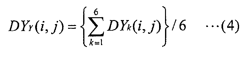 and is known. Furthermore, an X-position DXY(i, j) of the
mark DMY(i, j) is determined upon design, and is known.
and is known. Furthermore, an X-position DXY(i, j) of the
mark DMY(i, j) is determined upon design, and is known.
Detection of arrangement coordinate positions of
shot areas on a plurality of wafers W (e.g., wafers for
one lot) on which similar patterns (including the first
number of marks) are formed by wafer processing up to the
previous layer will be described below based on the flow
chart shown in Fig. 5 with reference to other drawings as
needed.
In step 201 in Fig. 5, the control unit 39 selects P
(> 1) sample sets Sp{MX(ipm, jpm), MY(ips, jps)} (p = 1 to P,
m = 1 to M (third number), s = 1 to M, M > 4), and also Q
(> 1) replacement candidate sets Rq{MX(iqn, jqn), MY(iqt,
jqt)} (q = 1 to Q, n = 1 to N (fourth number), t = 1 to N,
4 ≤ N < M), and stores element information of the sample
sets Sp and replacement candidate sets Rq in the sample
set information storage area 42 in Fig. 3.
Note that M marks MX (ipm, jpm) and M marks MY(ips, jps)
as elements of each sample set Sp are respectively
selected not to line up upon design. Also, when
comparing any two of the sample sets Sp, each set includes
at least one element that the other does not include.
N marks MX(iqn, jqn) and N marks MY(iqt, jqt) as
elements of each replacement candidate set Rq are also
respectively selected not to line up upon design.
Furthermore, when comparing any two of the replacement
candidate sets Rq, each set includes at least one element
that the other does not include.
In this embodiment, the numbers of marks MX(ipm, jpm)
and marks MY(ips, jps) as elements of the sample set Sp are
equal to each other (M), but may be different from each
other. In such case, each of the numbers of marks MX(ipm,
jpm) and marks MY(ips, jps) as elements of the sample set Sp
must be three or more, and the total of them must be
larger than 6. Also, in this embodiment, the numbers of
marks MX(iqn, jqn) and marks MY(iqt, jqt) as elements of the
replacement candidate set Rq are equal to each other (N),
but may be different from each other. In such case as
well, each of the numbers of marks MX(iqn, jqn) and marks
MY(iqt, jqt) as elements of the replacement candidate set
Rq must be three or more, and the total of them must be
larger than 6.
The first wafer W is loaded onto the wafer holder 25
by a wafer loader (not shown), and alignment with coarse
accuracy (prealignment) is done by the main control
system 20 moving the wafer via the stage control system
19 so that marks MX(i, j) and MY(i, j) are placed within
the observation field of view of the alignment microscope
AS. Such prealignment is done by the main control system
20 (more specifically, control unit 39) via the stage
control system 19 on the basis of observation of the
outer shape of the wafer W, the observation result of
marks MX(i, j) and MY(i, j) in a broader field of view,
and position information (or velocity information) from
the wafer interferometer 18.
Referring back to Fig. 5, the positions of the marks
MX(ipm, jpm), MY(ips, jps), MX(iqn, jqn), and MY(iqt, jqt) as
elements of the sample sets Sp or replacement candidate
sets Rq are measured in subroutine 202.
In subroutine 202, the wafer W is moved to locate
the first mark (X-position detection mark MX(i11, j11)) at
the image pickup position of the alignment microscope AS
in step 211 in Fig. 6. Such movement is done under the
control of the main control system 20 via the stage
control system 19.
Subsequently, the alignment microscope AS picks up
an image of the mark MX (i11, j11) in step 212. Then, the
picked-up image data acquisition unit 31 stores inputted
picked-up image data IMD in the picked-up image data
storage area 41 in accordance with an instruction from
the control unit 39, thus acquiring picked-up image data
IMD.
In step 213, the mark information calculation unit
32 reads out picked-up image data associated with the
mark MX(i11, j11) from the picked-up image data storage
area 41, and extracts the X-positions of six edges as
position information in the mark MX(i11, j11) on the basis
of the picked-up image data and position information (or
velocity information) WPV from the wafer interferometer
18 in accordance with an instruction from the control
unit 39. In this manner, (FX1 (i11, j11), FX2(i11, j11),
FX3(i11, j11), FX4(i11, j11), FX5(i11, j11), FX6(i11, j11))
shown in Fig. 7 are extracted as the X-positions of the
six edges.
Such extraction of the X-positions of the edge can
be implemented by analyzing a waveform obtained by
scanning the picked-up image data along an XS(i11, j11)
axis which passes all the three line portions of the mark
MX(i11, j11) and is parallel to the X-axis, as shown in
Fig. 7, or by analyzing a waveform obtained by
integrating the picked-up image data in the Y-direction.
Note that the latter method requires a larger arithmetic
volume but can accurately extract the X-positions of the
edges.
Referring back to Fig. 6, in step 214 the mark
information calculation unit 32 calculates a position
FX (i11. j11) of the mark MX (i11, j11) and a probability
density PFX(i11, j11) of that position as follows on the
basis of the edge positions FXk(i11, j11) (k = 1 to 6) of
the mark MX (i11, j11) extracted in step 213, and edge
positions DXk(i11, j11) of a ideal mark DMX(i11, j11)
corresponding to the mark MX(i11, j11).
The mark information calculation unit 32 calculates
an X-position FX(i11, j11) of the mark MX (i11. j11) by
 More specifically, the average value of the edge
positions FXk(i11, j11) (k = 1 to 6) of the mark MX(i11,
j11) is calculated as the X-position FX(i11, j11) of the
mark MX (i11, j11).
More specifically, the average value of the edge
positions FXk(i11, j11) (k = 1 to 6) of the mark MX(i11,
j11) is calculated as the X-position FX(i11, j11) of the
mark MX (i11, j11).
The mark information calculation unit 32 then
calculates errors dFXk(i11, j11) of the measured edge
positions FXk(i11, j11) corresponding to ideal edge
positions DXk(i11, j11) by
dFXk (i11 , j11 ) = FXk (i11 , j11 ) - DXk (i11 , j11 )
and then calculates an average value dFX(i11, j11) and
standard deviation σX(i11, j11) of the errors dFXk(i11, j11)
by


Note that the X-position FX (i11. j11) of the mark
MX(i11, j11) given by equation (5), the X-position DXx(i11,
j11) of the aforementioned mark DMX(i11, j11), and the
average value dFX (i11, j11) of the errors dFXk(i11, j11)
satisfy:
FX (i11, j11) = DXx(i11, j11) + dFX (i11, j11) ··· (6A)
Hence, upon calculating the X-position FX(i11, j11) of the
mark MX (i11, j11), the value dFX (i11, j11) may be calculated
by equation (7), and the X-position may be calculated by
equation (6A) using this value in place of a calculation
given by equation (5).
Upon calculating the value dFX(i11, j11), in place of
a calculation given by equation (7), after the value
FX(i11, j11) has been calculated by equation (5), the value
dFX(i11, j11) can be calculated by
dFX(i11 , j11 ) = FX(i11 , j11 ) - DXx (i11 , j11 )
Since the generation factors of the errors dFXk(i11,
j11) are considered to be random, the mark information
calculation device 32 assumes that their distribution is
a normal distribution, and that a probability density
function fX11(dx) of the errors dFXk(i11, j11) is given by
 Based on such estimation, the mark
 information
calculation unit 32 calculates a probability density that
the value of a variable dx is dFX(i11, j11), i.e., an
occurrence probability pFX(i11, j11) that the X-position of
the mark MX (i11, j11) takes a value FX(i11, j11) by
pFX(i11 , j11 ) = fX11 (dFX(i11 , j11 ))
= {(2π)1/2 ·σX(i11 , j11 )}-1
The mark information calculation unit 32 stores the
position FX(i11, j11) of the mark MX (i11, j11) and its
occurrence probability pFX(i11, j11) calculated in this way
in the mark information storage area 43. In this manner,
calculations of the mark information that pertains to the
first mark MX(i11, j11) are completed.
Figs. 8A and 8B show an example wherein the
X-position FX(i11, j11) of the mark MX(i11, j11) and its
occurrence probability pFX(i11, j11) are calculated on the
basis of the measured edge positions FXk(i11, j11), and
Figs. 9A and 9B show another example.
In the example shown in Figs. 8A and 8B, the errors
dFXk(i11, j11) of the measured edge positions FXk(i11, j11)
corresponding to the ideal edge positions DXk(i11, j11) are
relatively uniform, as shown in Fig. 8A. Note that
Fig. 8A illustrates the edge positions DXk(i11, j11) as
elements on the X-axis in the mark DMX (i11, j11), and has
symbols DXk attached onto those elements. Also, Fig. 8A
illustrates the edge positions FXk(i11, j11) as elements on
the X-axis in the mark MX(i11, j11), and has symbols FXk
attached onto those elements.
In the mark MX(i11, j11) for which the edge positions
FXk (i11, j11) shown in Fig. 8A are measured, the
probability density function fX11(dx) of the error
distribution is steep, as shown in Fig. 8B. That is, the
standard deviation σX(i11, j11) is small. As a result, a
probability density pFX(i11, j11) that an error takes a
value dFX(i11, j11), i.e., the X-position of the mark
MX(i11, j11) takes a value FX(i11, j11) becomes larger than
that in Fig. 9B to be described below.
Meanwhile, in the example shown in Figs. 9A and 9B,
the errors dFXk(i11, j11) of the measured edge positions
FXk(i11, j11) corresponding to the ideal edge positions
DXk(i11, j11) greatly vary, as shown in Fig. 9A. Note that
Fig. 9A uses the same expression method as Fig. 8A.
In the mark MX(i11, j11) for which the edge positions
FXk(i11, j11) shown in Fig. 9A are measured, the
probability density function fX11(dx) of the error
distribution is gradual, as shown in Fig. 9B. That is,
the standard deviation σX(i11, j11) of the error
distribution takes a large value. As a result, the
probability density pFX(i11, j11) that an error takes the
value dFX(i11, j11), i.e., the X-position of the mark
XM(i11, j11) assumes the value FX(i11, j11) becomes smaller
than that in Fig. 8B mentioned above.
Referring back to Fig. 6, it is checked in step 215
if mark information calculations for all the selected
marks are complete. In the aforementioned process, since
the calculations of mark information of only one mark
MX (i11, j11), i.e., the mark position FX (i11, j11) of the
mark MX(i11, j11) and its probability density pFX(i11, j11)
are complete, the answer in step 215 is NO, and the
sequence advances to step 216.
In step 216, the control unit 39 moves the wafer W
to a position where the next mark falls within the image
pickup field of view of the alignment microscope AS.
Such movement of the wafer W is done by moving the wafer
stage WST when the control unit 39 controls the wafer
drive unit 24 via the stage control system 19 on the
basis of the prealignment result.
After that, the X-positions FX(ipm, jpm) of other
marks MX(ipm, jpm) and their probability densities pFX(ipm,
jpm), the Y-positions FY(ips, jps) of marks MY(ips, jps) and
their probability densities pFY(ips, jps), the X-positions
FX(iqn, jqn) of marks MX(iqn, jqn) and their probability
densities pFX(iqn, jqn), and the Y-positions FY(iqt, jqt) of
marks MY(iqt, jqt) and their probability densities pFY(iqt,
jqt) are computed in the same manner as in the case of the
aforementioned mark MX(i11, j11) until it is determined in
step 215 that the mark information (mark positions and
probability densities) of all the selected marks has been
calculated. If the mark information of all the selected
marks has been calculated, and the answer in step 215 is
YES, subroutine 202 ends. And the sequence advances to
step 203 in Fig. 5.
In step 203, the parameter calculation unit 33 reads
out the X-positions (ipm, jpm) (m = 1 to M) of the marks
MX(ipm, jpm) and their probability densities pFX(ipm, jpm),
and the Y-positions FY(ips, jps) (s = 1 to M) of the marks
MY(ips, jps) and their probability densities pFY(ips, jps)
from the mark information storage area 43 for each sample
set Sp in accordance with an instruction from the control
unit 39. The parameter calculation unit 33 then
calculates the estimations of parameters which uniquely
specify the arrangement of shot areas SA(i, j).
The marks MX(i, j) and MY(i, j) formed on the wafer
W deviate from their ideal positions due to a mismatch
between a stage coordinate system (X, Y) which specifies
the position of the wafer stage WST, and the arrangement
coordinate system of shot areas as a design coordinate
system, i.e., a wafer coordinate system (α, β), and such
a mismatch occurs due to the following four main factors.
When the aforementioned error factors 1 ○ to 4 ○ are
added, a pattern to be transferred to a target position
(DX, DY), in terms of design, on the wafer coordinate
system (α, β) is transferred to a position (EX, EY) on
the stage coordinate system (X, Y), of which the position
is given by
 Note that various other error factors are also present in
addition to the aforementioned ones upon actual transfer,
and the position (EX, EY) is considered as an expected
transfer position.
Note that various other error factors are also present in
addition to the aforementioned ones upon actual transfer,
and the position (EX, EY) is considered as an expected
transfer position.
In general, since the orthogonality error w and
residual rotation error can be considered as
infinitesimal amounts, the target transfer position (DX,
DY) and expected transfer position (EX, EY) are related
by
 which expresses a first-order approximation of the
trigonometric function in equation (11).
which expresses a first-order approximation of the
trigonometric function in equation (11).
In the following description, equation (12) can also
be expressed by
 where
where
A11 = RX
A12 = -RX ·(w + 0)
A21 = RY ·
A22 = RY
That is, parameters which uniquely specify the
arrangement of shot areas SA(i, j) are six parameters A11,
A12, A21, A22, Ox, and OY. In step 203, the parameter
calculation unit 33 calculates the estimations of these
six parameters of each sample set SP as follows.
The parameter calculation unit 33 calculates an
expected transfer X-position EX(ipm, jpm) of each mark
MX(ipm, jpm) from the ideal transfer position (DXX(ipm, jpm),
DYX(ipm, jpm)) of the mark MX(ipm, jpm) using equation (13),
the EX(ipm, jpm) containing the parameters. Subsequently,
the parameter calculation unit 33 calculates an expected
transfer Y-position EY(ips, jps) of each mark MY(ips, jps)
from the ideal transfer position (DXY(ips, jps), DYY(ips,
jps)) of the mark MY(ips, jps) using equation (13), the
EY(ips, jps) containing the parameters.
Then, the parameter calculation unit 33 calculates
an error δXpm of the X-position FX(ipm, jpm), calculated
based on the measurement result, relative to the expected
transfer X-position EX(ipm, jpm) for each mark MX(ipm, jpm)
by
δXpm = FX(ipm , jpm ) - EX(ipm , jpm )
The parameter calculation unit 33 also calculates an
error δYps of the Y-position FY(ips, jps), calculated based
on the measurement result, relative to the expected
transfer Y-position EY(ips, jps) for each mark MY(ips, jps)
by
δYps = FY(ips , jps ) - EY(ips , jps )
Normally, it is said that the more identical the
ideal mark shape and actually transferred mark shape are,
the more accurate mark transfer onto the wafer W has been
done (except for transfer position accuracy). Therefore,
the mark position is more reliable as it is calculated
from the measurement results of the edge positions of the
mark having a shape more identical to the ideal mark's
shape. Also, the reliability level of the calculated
mark position depends on the occurrence probability of
the mark position, i.e., the probability density.
Hence, the parameter calculation unit 33 evaluates
the errors δXpm and δYps calculated by equations (18) and
(19) using the probability densities pFX (ipm, jpm) and
pFY(ips, jps), and calculates evaluated errors εXpm and εYps
by
εXpm = pFX(ipm , jpm ) ·δXpm
εYps = pFY(ips , jps )·δYps
The parameter calculation unit 33 then calculates
the estimations of the six parameters A11, A12, A21, A22, OX,
and OY which minimize a variation Sp given by
 by applying the method of least squares on the basis of
the evaluated errors εXpm and εYps. More specifically, the
by applying the method of least squares on the basis of
the evaluated errors εXpm and εYps. More specifically, the
parameter calculation unit 33 calculates estimations A11p,
A12p, A21p, A22p, OXp, and OYp of the six parameters A11, A12,
A21, A22, OX, and OY by solving simultaneous equations made
up of six equations obtained by setting partial
differentials of the variation SP given by equation (22)
by the six parameters A11, A12, A21, A22, OX, and OY to zero.
The parameter calculation unit 33 stores P groups of
estimations (A11p, A12p, A21p, A22p, OXp, OYp) calculated in
this way in the estimation storage area 45.
The valid value calculation unit 34 reads out the P
sets of calculated estimations (A11p, A12p, A21p, A22p, OXp,
GYp) from the estimation storage area 45, and calculates
an X-position deviation σpX, Y-position deviation σpY, and
covariance σpXY associated with each sample set Sp upon
adopting each group of estimations as follows.
The valid value calculation unit 34 calculates the
expected transfer X-position EXp(ipm, jpm) of each mark
MX(ipm, jpm) from the ideal transfer position (DXX(ipm, jpm),
DYY(ipm, jpm)) of the mark MX(ipm, jpm) using the
estimations (A11p, A12p, A21p, A22p, OXp, OYp) as the values of
the parameters (A11, A12, A21, A22, OX, OY) in equation (13)
Subsequently, the valid value calculation unit 34
calculates the expected transfer Y-position EYp(ips, jps)
of each mark MY(ips, jps) from the ideal transfer position
(DXY(ips, jps), DYY(ips, jps)) of the mark MY(ips, jps).
The valid value calculation unit 34 then calculates
an error δpXpm of the X-position FX(ipm, jpm), calculated
based on the measurement result, relative to the expected
transfer X-position EXp(ipm, jpm) for each mark MX(ipm, jpm)
by
δp Xpm = FX (ipm , jpm ) - EXp (ipm , jpm )
Subsequently, the valid value calculation unit 34
calculates an error δpYps of the Y-position FY(ips, jps)
calculated based on the measurement result from the
expected transfer Y-position EYp(ips, jps) for each mark
MY(ips, jps) by
δp Yps = FY(ips , jps ) - EYp (ips , jps )
The valid value calculation unit 34 then evaluates
the errors δpXpm and δpYps calculated by equations (23) and
(24) using the probability densities pFX(ipm, jpm) and
pFY(ips, jps), and calculates evaluated errors εpXpm and
εpYps by
εp Xpm = pFX(ipm , jpm ) ·δp Xpm
εp Yps = pFY(ips , jps ) ·δp Yps
The valid value calculation unit 34 calculates an
X-position deviation σpX, Y-position deviation σpY, and
covariance σpXY respectively by
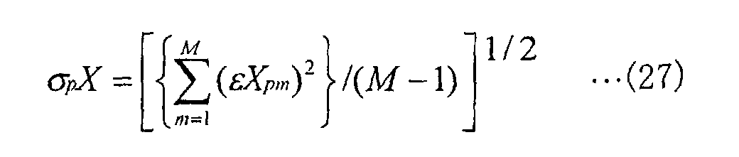


The valid value calculation unit 34 calculates a
deviation σp upon adopting the estimations (A11p, A12p, A21p,
A22p, OXp, OYp) by
σp ={(σp X )2 • (σp Y )2 -(σp XY )2 }1/2
The calculated deviations σp indicate the certainties
of the respective estimations (A11p, A12p, A21p, A22p, OXp,
OYp), i.e., the degrees by which the respective sample
sets Sp represent the entire marks MX and MY.
The parameter calculation unit 33 checks in step 204
if there are a plurality of sample sets Sp. In the above,
since the number of sample sets Sp is P (> 1), the answer
in step 204 is YES, and the sequence advances to step 205.
In step 205, on the basis of the P groups of
estimations (A11p, A12p, A21p, A22p, OXp, OYp) and deviations
σp that reflect the certainty, the valid value calculation
unit 34 calculates weighted mean of each parameter of the
estimations (A11p, A12p, A21p, A22p, OXp, OYp) using the values
(1/σp) as respective weight coefficients of the
estimations, and obtains a set of statistically valid
parameter values (A110, A120, A210, A220, OXo, OYo). That is,
the valid value calculation unit 34 computes





Also, the valid value calculation unit 34 calculates
deviation σo upon adopting the statistically valid
parameter values (A110, A120, A210, A220, OXo, OYo) by

The valid value calculation unit 34 stores the
statistically valid parameter values (A110, A120, A210, A220,
OXO, OYO) and deviation σo calculated in this way in the
valid value storage area 44 as parameter values (AU11, AU12,
AU21, AU22, OUX, OUY) and deviation σU used upon exposure
of the wafer W.
In subroutine 207, the evaluation unit 35 evaluates
in accordance with an instruction from the control unit
39 possibility of replacing the sample set Sp by any of
replacement candidate sets Rq.
In subroutine 207, the evaluation unit 35 reads out
X-positions FX(ipn, jqn) (n = 1 to N) of marks MX(iqn, jqn)
and their probability densities pFX(iqn, jqn), and
Y-positions FY(iqt, jqt) (t = 1 to N) of marks MY(iqt, jqt)
and their probability densities pFY(iqt, jqt) from the mark
information storage area 43 in step 221 of Fig. 10 in the
same manner as in the aforementioned case of the sample
sets Sp. The evaluation unit 35 calculates a estimation
(A11q, A12q, A21q, A22q, OXq, and OYq) for parameters A11, A12,
A21, A22, OX, and OY which uniquely specify the arrangement
of shot areas SA(i, j) in the same manner as in the case
of the sample sets Sp.
The evaluation device 35 then calculates X-position
deviations σqX, Y-position deviations σqY, and covariances
σqXY of respective replacement candidate sets Rq upon
adopting the Q sets of calculated estimations (A11q, A12q,
A21q, A22q, OXq, OYq), and also deviations σq upon adopting
the Q sets of calculated estimations (A11q, A12q, A21q, A22q,
OXq, OYq) in the same manner as in the case of the sample
sets Sp. The calculated deviations σq indicate the
certainties of the respective estimations (A11q, A12q, A21q,
A22q, OXq, OYq), i.e., the degrees by which the respective
replacement candidate sets Rq represent the entire marks
MX and MY.
In step 222, the evaluation unit 35 reads out the
statistically valid parameter values (AU11, AU12, AU21, AU22,
OUX, OUY) and deviation σU from the valid value storage
area 44, and evaluates similarities with the estimations
(A11q, A12q, A21q, A22q, OXq, OYq) and deviations σq associated
with the replacement candidate sets Rq. Such evaluation
is done by comprehensively considering a similarity F of
parameter values given by
Fq = A11q - AU11 + A12q - AU12
+ A21q - AU21 + A22q - AU22
+ OXq - OUX + OYq - OUY
and a similarity G of deviation values given by
Gq = σq - σU
For example, if
C1 < Fq × Gq
for a predetermined value C1, it may be determined that
the two sets are similar. In such a case, the similarity
F of the parameter values and the similarity G of
deviation values are equally handled.
On the other hand, if
C2 < Fq + Gq
for a predetermined value C2, it may be determined that
the two sets are similar. In such a case as well, the
similarity F of the parameter values and the similarity G
of deviation values are equally handled.
Also, if
C3 < Fq + 3Gq
for a predetermined value C3, it is evaluated that the
two sets are similar. In such case, the similarity F of
the parameter values and the triple of the similarity G
of deviation values are equally handled.
The evaluation unit 35 checks in step 223 if there
is a replacement candidate set Rq that has been found to
be similar as a result of evaluation in step 222. If NO
in step 223, the evaluation unit 35 sends a report
indicating this to the control unit 39. The control unit
39 receives the report and selects new Q replacement
candidate sets, and stores them in the sample set
information storage area 42 in step 225. In this fashion,
the process of subroutine 207 executed if NO in step 223
ends.
On the other hand, if YES in step 223, the
evaluation unit 35 replaces the replacement candidate set
information in the sample set information storage area 42
by information that pertains to only the replacement
candidate set or sets found to be similar.
The evaluation unit 35 checks in step 226 if there
is a replacement candidate set that is successively found
to be similar a predetermined number of times. For
example, when the predetermined number of times is three,
since similarity evaluation has been done only once for
only one wafer, the answer in step 226 is NO, and then
the process of subroutine 207 ends.
If the predetermined number of times is one, the
answer in step 226 is YES, and the evaluation unit 35
selects a replacement candidate set having the highest
similarity from those found to be similar as a new sample
set, and replaces the sample set information in the
sample set information storage area 42 by information
that pertains to the new sample set in step S227, thus
ending the process of subroutine 207. In such a case,
the number of sample sets is one from here on.
Parallel to the aforementioned process of subroutine
207, the control unit 39 calculates the arrangement
coordinate positions of shot areas SA(i, j) using the
parameter values (AU11, AU12, AU21, AU22, OUX, OUY)
calculated in step 205 in Fig. 5. Then, the reticle R
and wafer W are aligned on the basis of the calculated
shot area arrangement under the control of the control
unit 39, and the wafer W and reticle R are synchronously
moved at a velocity ratio corresponding to the projection
magnification in opposite directions along the scan
direction (Y-direction) while a slit-like illumination
area (the center of which nearly coincides with the
optical axis AX) is illuminated with illumination light
IL, thus transferring a pattern on a pattern area of the
reticle R onto each shot area SA(i, j) in the reduced
scale. Upon completion of pattern transfer onto all the
shot areas SA(i, j), the wafer is unloaded under the
control of the control unit 39.
If exposure of the first wafer W is complete, and
the process of the subroutine has ended in this way, the
control unit 39 checks in step 208 in Fig. 5 if exposure
of all wafers (e.g., wafers for one lot) is complete. In
the above process, since exposure of only the first wafer
is complete, the answer in step 208 is NO. The next
wafer is loaded onto the wafer holder 25 by the wafer
loader (not shown) in the same manner as the first wafer,
and alignment with coarse accuracy (prealignment) is done
by the main control system 20 moving the wafer W via the
stage control system 19 so that marks MX(i, j) and MY(i,
j) can be placed within the observation field of view of
the alignment microscope AS. After that, steps 202 to
207 in Fig. 5 are repeated for each wafer W in the same
manner as the first wafer until YES is determined n step
208.
If it is determined in step 208 in Fig. 5 that
exposure of all wafers is complete, the exposure process
ends.
If replacement candidate sets which are successively
determined first to be similar to the sample set a
predetermined number of times are found in step 226 in
Fig. 10, since the most similar one of those sets is used
as the subsequent sample set, the number of sample sets
becomes one. As a result, NO is determined in step 204
in Fig. 5 executed thereafter, and step 206 is executed
in place of step 205 mentioned above. That is, the
estimations of position parameters calculated based on
the position measurement results of marks MX and MY
contained in the single sample set are directly adopted
as parameter values (AU11, AU12, AU21, AU22, OUX, OUY) used
upon exposure of the wafer W.
According to the exposure apparatus of this
embodiment with the aforementioned arrangement and
operations, a plurality of sample sets are selected
initially, and position parameters are calculated based
on the result of estimating the position distribution of
the entire marks MX and MY according to respective groups
of the estimations and their certainties of position
parameters calculated for the sample sets. Accordingly,
statistically valid position parameter values can be
obtained. Therefore, the wafer W can be aligned very
accurately, and the pattern transfer accuracy can be
improved.
Furthermore, if a set appropriate to replace the
sample sets is found when searching for a replacement
candidate set that reflects the position distribution of
the entire marks MX and MY as much as the sample sets
used to calculate the statistically valid position
parameter values and contains fewer elements than any
sample set, the appropriate set is used as a new sample
set. Therefore, since the time required for aligning a
wafer W can be shortened while maintaining statistical
validity of the obtained position parameters, the
throughput can be improved.
In addition, a mark position is calculated on the
basis of the position information of each position
measurement mark (alignment mark) obtained through
measuring the alignment marks associated with each sample
set, i.e., the measurement results of a plurality of edge
positions of each alignment mark; the certainty of that
mark position is calculated from the design values of the
edge positions and errors, and parameter values
(estimations) that uniquely specify the arrangement of
shot areas (i, j) on the wafer W are calculated for each
sample set using the certainty as the weight. Therefore,
because the arrangement of the shot areas (i, j) on the
wafer W is calculated using the finally obtained accurate
parameter values to align the wafer W, accurate alignment
can be performed, and pattern transfer with high overlap
accuracy can be achieved.
The manufacture of a device using the exposure
apparatus and method of this embodiment will be described
below.
Fig. 11 is a flow chart of production of devices
(semiconductor chips such as IC or LSI, liquid crystal
panels, CCD's, thin-film magnetic heads, micro machines,
or the like) in this embodiment. As shown in Fig. 11, in
step 301 (design step) function/performance design for
the devices (e.g., circuit design for semiconductor
devices) is performed, and also pattern design is
performed. In step 302 (mask fabrication step), a mask
formed with the designed circuit pattern is fabricated.
On the other hand, in step 303 (wafer preparation step) a
wafer is prepared using material such as silicon and the
like.
In step 304 (wafer process step), an actual circuit
and the like are formed on the wafer by lithography, as
will be described later, using the mask and wafer
prepared in steps 301 to 303. In step 305 (device
assembly step), devices are assembled using the wafer
processed in step 304. This step 305 includes processes
such as an assembly process (dicing, bonding), packaging
step (chip encapsulation), and the like.
Finally, in step 306 (inspection step) inspections
such as an operation confirmation test, durability test,
and the like of the devices manufactured in step 305 are
performed. After these steps, the process is complete,
and the devices are shipped out.
Fig. 12 shows a detailed, exemplary flow of step 304
for manufacturing semiconductor devices. As shown in
Fig. 12, the wafer surface is oxidized in step 311
(oxidation step). In step 312 (CVD step), an insulation
film is formed on the wafer surface. In step 313
(electrode formation step), electrodes are formed on the
wafer by deposition. In step 314 (ion implantation step),
ions are implanted into the wafer. Steps 311 to 314
mentioned above constitute a pre-process of each step in
the wafer process, and is selectively executed in
accordance with the process required in each step.
Upon completion of the pre-process in each step of
the wafer process, a post-process steps is performed as
follows. In this post-process, the wafer is coated with
a photosensitive agent in step 315 (resist formation
step), and the above exposure apparatus transfers the
circuit pattern on the mask onto the wafer aligned using
the aforementioned scheme, in step 316 (exposure step).
The exposed wafer is developed in step 317 (development
step), and an exposing member of portions other than
portions where the resist remains is removed by etching
in step 318 (etching step). Then, the resist that has
become unnecessary after etching is removed in step 319
(resist removal step).
By repeating the pre- and post-process steps, multi-layer
circuit patterns are formed on the wafer.
In this way, devices having a micro-pattern
accurately formed thereon are manufactured with high
mass-productivity.
In the above embodiment, upon detecting the edge
positions of the marks MX(ipm, jpm) and MY(ips, jps), one
edge position is extracted for each edge using the
picked-up image data on a single axis parallel to the
direction of the mark pattern change or the integrated
data in the direction perpendicular to the direction of
the mark pattern change, as described above.
Alternatively, as shown in Fig. 13 that representatively
shows a mark MX(ipm, jpm), edge positions can be extracted
along each of a plurality of (= H) axes XSh(ipm, jpm) (h =
1 to H) parallel to the direction in which the pattern of
the mark MX(ipm, jpm) changes. In such a case, edge
positions FXkh(ipm, jpm) (k = 1 to 6, h = 1 to H) are
extracted.
Then, an X-position FX(ipm, jpm) of the mask MX(ipm,
jpm) is calculated by

Also, an error dFXkh(ipm, jpm) of each edge position
FXkh (ipm, jpm) from the ideal edge position DXk(ipm, jpm) is
calculated by
dFXkh (ipm , jpm ) = FXkh (ipm , jpm ) - DXk (ipm , jpm )
After that, an average value dFX(ipm, jpm) and standard
deviation σX (ipm, jpm) of the errors dFXkh (ipm, jpm) are
respectively calculated by


The X-position FX(ipm, jpm) and standard deviation
σX(ipm, jpm) of the mark MX(ipm, jpm) calculated in this way
are statistically more valid than those in the
aforementioned embodiment, since the number of extracted
edge positions is larger than that in the above
embodiment.
Note that the Y-position FY(ips, jps) of each mark
MY(ips, jps) can be calculated in the same manner as the
mark MX(ipm, jpm). In such case as well, the calculated Y
position FY(ips, jps) and standard deviation σY(ips, jps) of
the mark MY(ips, jps) are statistically more valid than
those in the above embodiment, since the number of
extracted edge positions is larger than that in the above
embodiment.
After that, optimal values of six parameters that
uniquely specify the arrangement of shot areas SA(i, j)
on the wafer W are calculated in the same manner as in
the above embodiment. Since the optimal values of the
six parameters are calculated based on statistically more
valid mark positions and their certainties than the above
case, higher accuracy than in the above embodiment can be
assured.
In the above embodiment, the aforementioned six
parameters are used as those for uniquely specifying the
arrangement of shot areas SA(i, j) on the wafer W.
Alternatively, even when the arrangement of shot areas
SA(i, j) are uniquely specified by more parameters than
the above embodiment, their optimal values can be
accurately calculated as in the above embodiment.
More specifically, in the above embodiment, upon
aligning shot areas SA(i, j) on the wafer, even when
appropriate values of parameters that specify the
arrangement of representative points, e.g. central points
of the shot areas SA(i, j), are calculated, and the
central point of a given shot area SA(i, j) is aligned
using those parameters, sufficiently high accuracy of
superposition cannot always be obtained. Such problem is
caused by the following three major factors, as disclosed
in, e.g., Japanese Patent Laid-Open Nos. 6-275496 and
6-349705.
5 ○ Rotation of shot region: This is caused when a
reticle R has rotated with respect to the stage
coordinate system (X, Y) upon transferring a pattern
formed on the reticle R onto a wafer W or when yawing is
accidentally mixed in the movement of a wafer stage WST
upon scanning exposure, and is expressed by a rotation
error of the wafer coordinate system (α, β) with respect
to a shot coordinate system having coordinate axes
parallel to the α- and β-axes.
6 ○ Orthogonality of shot region: This is caused by
distortion of a pattern formed on a reticle R, distortion
(distortion error) of a projection optical system PL, and
the like, and is expressed by an orthogonality error χ.
7 ○ Linear expansion/shrinkage of shot region: This is
caused by an error of the projection magnification upon
projecting a pattern formed on a reticle R onto a wafer W
or by the wafer entirely or partially expanding or
shrinking due to a formation process or the like. This
expansion/shrinkage amount is expressed by wafer scaling
values rX and rY in the coordinate axis directions (i.e.,
α- and β-directions) of the shot coordinate system. Note
that the wafer scaling value rX in the α-direction is
represented by the ratio between the actually measured
value and design value of the distance between two points
in the α-direction on the wafer W, and that the wafer
scaling value rY in the β-direction is represented by the
ratio between the actually measured value and design
value of the distance between two points in the
β-direction.
The ideal position (DX, DY) in a shot area is
expressed by
DX = CX + SX
DY = CY + SY
using a central coordinate position (CX, CY) of that shot
region, and a coordinate position (SX, SY) of the
position (DX, DY) relative to that coordinate position
(CX, CY) on the shot coordinate system. Therefore, when
error factors 5 ○ to 7 ○ are added to the aforementioned
error factors 1 ○ to 4 ○, a pattern to be transferred at the
ideal position (DX, DY) on the wafer coordinate system (α,
β) is transferred to a position (EX, EY) on the stage
coordinate system (X, Y) given by
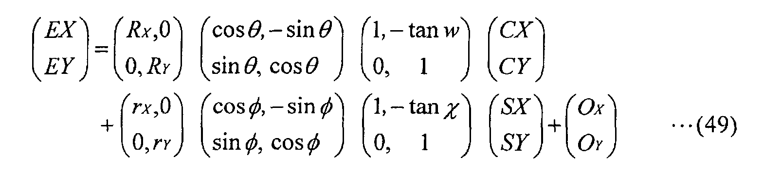 Note that various other error factors are also present in
addition to the aforementioned ones upon actual transfer,
and that the position (EX, EY) is considered as an
expected transfer position.
Note that various other error factors are also present in
addition to the aforementioned ones upon actual transfer,
and that the position (EX, EY) is considered as an
expected transfer position.
In general, since the orthogonality errors w and χ,
and residual rotation errors and can be considered as
infinitesimal amounts, the designed transfer position (DX,
DY) and expected transfer position (EX, EY) are related
by
 which expresses a first-order approximation of the
trigonometric function in equation (49).
which expresses a first-order approximation of the
trigonometric function in equation (49).
In the following description, equation (50) is also
expressed by
 where
where
B11 = rX
B12 = -rX ·(χ + )
B21 = rY ·
B22 = rY
That is, parameters which uniquely specify the
arrangement of shot areas SA(i, j) are ten parameters A11,
A12, A21, A22, B11, B12, B21, B22, OX, and OY. In order to
obtain optimal values of the ten parameters, four
two-dimensional marks WMp(i, j) (p = 1 to 4), which do
not line up upon design and the patterns of which change
in the X- and Y-directions, are formed on each shot area
SA(i, j), as shown in, e.g., Fig. 14. Note that the
number of wafer marks is not limited to four, and can be
three or more. As the two-dimensional marks WMp, marks
having patterns shown in, e.g., Figs. 15A to 15D, can be
used.
Then, more than five two-dimensional marks WMp(im,
jm) (m > 5) including three out of four two-dimensional
marks WMp(i, j) on any shot area are measured. After
that, the X- and Y-positions of the two-dimensional marks
WMp(im, jm), and the probability densities of those X- and
Y-positions are calculated in the same manner as in the
above embodiment, thus calculating optimal values of the
ten parameters A11, A12, A21, A22, B11, B12, B21, B22, OX, and
OY.
In this way, the arrangement of shot areas can be
obtained that takes into account the rotation,
orthogonality and expansion/shrinkage of each shot region.
Furthermore, optimal values of the error factors (rX, rY,
χ, ) are calculated using equations (32) to (35) for the
aforementioned controllable error factors (rX, rY, χ, )
and four parameters (B11, B12, B21, B22) of the ten
parameters, the optimal values of which have been
calculated, and in accordance with those error factors,
corrected are the magnification of the projection optical
system PL, the synchronous velocity ratio upon scanning
exposure, synchronous moving directions upon scanning
exposure, and the like. Thus, the accuracy of
superposition is further improved.
In the above embodiment, a plurality of initial
sample sets are used, but if one sample set from which
accurate position parameters can be calculated is known,
that sample set may be used as only one initial sample
set. Even in such a case, the processing flow of the
above embodiment can be applied. Since the number of
sample sets is one from the beginning, in the processing
flow of the above embodiment, the answer in step 204 is
always NO.
In the above embodiment, whether or not it is
possible to reduce the number of elements of a sample set
is evaluated by comparing the position parameter values
and their certainties calculated from the sample set, and
estimations of position parameters and their certainties
calculated from each of a plurality of replacement
candidate sets. Alternatively, such evaluation can be
performed by so-called cross-verification.
More specifically, the position errors of marks MX
and MY included in a sample set are calculated using the
estimations of the position parameters calculated for
each replacement candidate set, and the position error
distribution of the marks MX and MY included in the
sample set is calculated based on that calculation result,
thus evaluating if each replacement candidate set has
statistical characteristics equivalent to that of the
sample set. In this case, replacement possibility can be
evaluated without calculating the position parameter
values and their certainties from the sample set. Such
cross-verification is particularly effective when the
replacement candidate set is a subset of the sample set.
In the above embodiment, upon reducing the number of
elements of a sample set, a plurality of initial sample
sets are replaced by one new sample set. Alternatively,
the number of elements of each of the plurality of
initial sample sets may be reduced. In this case, for
each sample set, a new sample set is searched for that
has characteristics equivalent thereto in the statistical
characteristics of position errors of marks and consists
of fewer elements.
In the above embodiment, one-dimensional marks MX
and MY are used. Alternatively, two-dimensional marks
shown in Figs. 15A to 15D may be used. Also, upon
calculating the ten parameters, one-dimensional marks MX
and MY may be used. As the two-dimensional mark, for
example, a box-in-box mark may be used in addition to
those shown in Figs. 15A to 15D. Upon detecting the
two-dimensional position of such a two-dimensional mark,
the aforementioned one-dimensional position detection
process may be performed twice, or two-dimensional
template matching into which the above one-dimensional
template matching for one-dimensional signals is extended
may be performed on two-dimensional signal waveforms of
two-dimensional marks.
In the above embodiment, the off-axis alignment
method that measures the positions of alignment marks on
a wafer without the intervention of a projection optical
system is adopted. Alternatively, a TTL
(through-the-lens) scheme that measures the positions of
alignment marks on a wafer via a projection optical
system, or a TTR (through-the-reticle) that
simultaneously observes a wafer and reticle via a
projection optical system may be adopted. In the case of
the TTR scheme, upon observation, sample alignment senses
the position of a wafer mark where the deviation between
a reticle mark formed on the reticle and a wafer mark
formed on the wafer is zero.
In the above embodiment, the coordinate positions of
the shot areas are calculated. Alternatively, the step
pitch of each shot may be calculated.
In the above embodiment, the fly-eye lens is used as
an optical integrator (homogenizer). In place of the
fly-eye lens, a rod integrator may be used. In an
illumination optical system using the rod integrator, the
rod integrator is disposed such that its exit surface is
nearly conjugated with the pattern surface of a reticle R.
Such an illumination optical system using the rod
integrator is disclosed in, e.g., U.S. Patent
No. 5,675,401, and the disclosures in the above
U.S. Patent is incorporated herein by reference as long
as the national laws in designated states or elected
states, to which this international application is
applied, permit. Also, the fly-eye lens and rod
integrator may be combined, or two fly-eye lenses or rod
integrators may be disposed in series to build double
optical integrators.
In the above embodiment, the present invention is
applied to the step-and-scan scanning exposure apparatus.
However, the application range of the present invention
is not limited to such specific apparatus, and the
present invention can be suitably applied to a stationary
exposure apparatus such as a stepper or the like.
Even an exposure apparatus using, e.g., ultraviolet
rays may adopt as a projection optical system a
reflection system consisting of reflective optical
elements alone or a reflection/refraction system (a
catadioptric system) having both reflective and
refractive optical elements. As the catadioptric
projection optical system, a reflection/refraction system
which is disclosed in, e.g., Japanese Patent Laid-Open
No. 8-171054 and corresponding U.S. Patent No. 5,668,672,
Japanese Patent Laid-Open No. 10-20195 and corresponding
U.S. Patent No. 5,835,275, and the like, and has a beam
splitter and concave mirror as reflection optical
elements, or a reflection/refraction system which is
disclosed in Japanese Patent Laid-Open No. 8-334695 and
corresponding U.S. Patent No. 5,689,377, Japanese Patent
Laid-Open No. 10-3039 and corresponding U.S. Patent
Application No. 873,605 (application date: June 12, 1997),
and the like, and has a concave mirror and the like as
reflective optical elements without using any beam
splitter can be used. The disclosures in the above
Japanese Patent Laid-Opens and U.S. Patents are
incorporated herein by reference as long as the national
laws in designated states or elected states, to which
this international application is applied, permit.
In addition, a reflection/refraction system can be
employed which comprises a plurality of refraction
optical elements and two mirrors (a main mirror being a
concave mirror and a sub-mirror that is a back surface
mirror of which the reflection surface is formed on the
opposite side to the incident surface of a refraction
element or plane parallel plate) that are disposed along
one axis, and has the intermediate image, formed by those
refraction optical elements, of a reticle pattern again
imaged on a wafer using the main mirror and sub-mirror,
the reflection/refraction system being disclosed in
Japanese Patent Laid-Open No. 10-104513 and U.S. Patent
No. 5,488,229 corresponding thereto. In this
reflection/refraction system, the main mirror and sub-mirror
are disposed in series with the plurality of
refraction optical elements, and an illumination light
passes through a portion of the main mirror, is reflected
by the sub-mirror and the main mirror in turn, passes
through a portion of the sub-mirror and reaches the wafer.
The disclosures in the above Japanese Patent Laid-Open
and U.S. Patent are incorporated herein by reference as
long as the national laws in designated states or elected
states, to which this international application is
applied, permit.
Furthermore, as the reflection/refraction-type
projection optical system, a reduction system may be
employed which has, e.g., a circular image field, is
telecentric on both the object plane side and image plane
side, and has a reduction ratio of, e.g., 1/4 or 1/5.
Also, in a scanning exposure apparatus comprising this
reflection/refraction-type projection optical system, the
illumination area of the illumination light may be a
rectangular-slit-shaped area whose center almost
coincides with the optical axis of the projection optical
system and which extends along a direction almost
perpendicular to the scanning direction of a reticle or
wafer. By using a scanning exposure apparatus comprising
such a reflection/refraction-type projection optical
system, it is possible to accurately transfer a fine
pattern of about 100nm L/S pattern onto wafers even with
F2 laser light having, for example, the wavelength of
157nm as exposure light.
Furthermore, as a vacuum ultraviolet light, ArF
excimer laser light or F2 laser light is used. However, in
a case of containing only a beam-monitor mechanism and
reference wavelength light source in the same environment
-controlled chamber as the projection optical system, a
higher harmonic wave may be used which is obtained with
wavelength conversion into ultraviolet by using nonlinear
optical crystal after having amplified a single
wavelength laser light, infrared or visible, emitted from
a DFB semiconductor laser device or a fiber laser by a
fiber amplifier having, for example, erbium (or erbium
and ytterbium) doped.
For example, considering that the oscillation
wavelength of a single wavelength laser is in the range
of 1.51 to 1.59 um, an eight-time-higher harmonic wave of
which the wavelength is in the range of 189 to 199nm or a
ten-time-higher harmonic wave of which the wavelength is
in the range of 151 to 159nm is emitted. Especially, when
the oscillation wavelength is in the range of 1.544 to
1.553um, an eight-time-higher harmonic wave of which the
wavelength is in the range of 193 to 194nm, that is,
almost the same as ArF excimer laser light (ultraviolet
light) is obtained, and when the oscillation wavelength
is in the range of 1.57 to 1.58um, a ten-time-higher
harmonic wave of which the wavelength is in the range of
157 to 158nm, that is, almost the same as F2 laser light
(ultraviolet light) is obtained.
Furthermore, when the oscillation wavelength is in
the range of 1.03 to 1.12um, a seven-time-higher harmonic
wave of which the wavelength is in the range of 147 to
160nm is emitted, and, especially, when the oscillation
wavelength is in the range of 1.099 to 1.106um, a seven-time-higher
harmonic wave of which the wavelength is in
the range of 157 to 158nm, that is, almost the same as F2
laser light (ultraviolet light) is obtained. In this case,
for example, ytterbium-doped fiber laser can be employed
as the single wavelength laser.
Moreover, the present invention can be applied not
only to an exposure apparatus for producing micro devices
such as semiconductor devices but also to an exposure
apparatus that transfers a circuit pattern onto a glass
substrate or silicon wafer so as to produce reticles or
masks used by a light exposure apparatus, EUV (Extreme
Ultraviolet) exposure apparatus, X-ray exposure apparatus,
electron beam exposure apparatus, etc. Incidentally, in
an exposure apparatus using DUV (far ultraviolet) light
or VUV (vacuum ultraviolet) light, a transmission-type
reticle is employed in general. And as the substrate of
the reticle, quartz glass, quartz glass with fluorine
doped, fluorite, magnesium fluoride, or quartz crystal is
employed. And an X-ray exposure apparatus of a proximity
method or electron beam exposure apparatus employs a
transmission-type mask (stencil-mask, membrane-mask); an
EUV exposure apparatus employs a reflection-type mask,
and as the substrate of the mask, silicon wafer or the
like is employed.
Note that the present invention can be applied not
only to a wafer exposure apparatus used in the production
of semiconductor devices but also to an exposure
apparatus that transfers a device pattern onto a glass
plate and is used in the production of displays such as
liquid crystal display devices and plasma displays, an
exposure apparatus that transfers a device pattern onto a
ceramic plate and is used in the production of thin
magnetic heads, and an exposure apparatus used in the
production of pick-up devices (CCD, etc.).
In addition, in the above embodiment, positional detection of the alignment marks on a wafer and alignment of the wafer have been described. However, positional detection and alignment according to the present invention can be applied to positional detection of the alignment marks on a reticle and alignment of the reticle, and also to other units than exposure apparatuses such as a unit to observe objects and a unit that is used to detect positions of objects and align them in an assembly line, process line or inspection line.
In addition, in the above embodiment, positional detection of the alignment marks on a wafer and alignment of the wafer have been described. However, positional detection and alignment according to the present invention can be applied to positional detection of the alignment marks on a reticle and alignment of the reticle, and also to other units than exposure apparatuses such as a unit to observe objects and a unit that is used to detect positions of objects and align them in an assembly line, process line or inspection line.
As has been described in detail above, according to
the position detection method and position detection
apparatus of the present invention, since a statistical
process is executed on the basis of position information
of position detection points obtained by measurement of
the position detection points on an object, position
information of any area on the object is accurately and
efficiently detected. Therefore, the position detection
method and position detection apparatus of the present
invention are suitable for detecting the position of any
area on an object.
Also, according to the exposing method and exposure
apparatus of the present invention, the positions of a
predetermined number of alignment marks formed on a
substrate are detected using the position detection
method of the present invention, and a predetermined
pattern is transferred onto divided areas while aligning
the substrate on the basis of the detection result.
Therefore, the exposing method and exposure apparatus of
the present invention are suitable to perform
multi-exposure for forming a multi-layer pattern with
improved accuracy of superposition between layers. For
this reason, the exposing method and exposure apparatus
of the present invention are suitable for mass-production
of devices having a fine pattern.
Claims (69)
- A position detection method for detecting position information of any area on an object provided with a plurality of position-measurement-points, the position detection method comprising:a measurement step of selecting more position-measurement-points than a minimum number of measurements required to calculate values of a predetermined number of parameters, which uniquely specify position information of any area on the object, from the plurality of position-measurement-points and measuring pieces of position information of the respective selected position-measurement-points;an estimation step of calculating respective positions of the selected position-measurement-points, based on the measurement results of the pieces of position information, and estimating probability density functions which each represent occurrence probability of the calculated position for respective one of the selected position-measurement-points;a probability density calculation step of calculating probability density of the calculated position of each of the position-measurement-points, based on respective one of the probability density functions; anda parameter calculation step of evaluating an error of each calculated position relative to respective reference position while using the respective calculated probability density's value as a piece of weight information and calculating values of the predetermined number of parameters, based on the evaluated errors.
- The position detection method according to claim 1, wherein the reference positions are determined in advance based on design information.
- The position detection method according to claim 1, wherein the error evaluation is performed by multiplying the error of each calculated position relative to the respective reference position by the respective probability density.
- The position detection method according to claim 1, wherein the probability density functions are probability density functions of normal distribution.
- The position detection method according to claim 1, wherein position measurement marks are formed at the position-measurement-points.
- The position detection method according to claim 5, wherein a plurality of position detection marks formed at the plurality of position-measurement-points include a first number of first marks of which surface states change in a first direction, and
wherein the piece of position information of each first mark measured in the measurement step comprises pieces of position information at a plurality of feature portions of each first mark in the first direction. - The position detection method according to claim 6, wherein for each of the selected first marks, the measurement step measures the piece of position information at a plurality of positions lined in a direction crossing the first direction.
- The position detection method according to claim 6, wherein surface state of each of the first marks changes also in a second direction different from the first direction, and
wherein the piece of position information of each first mark measured in the measurement step consists of position information, in the first direction, of a plurality of feature portions lined in the first direction and position information, in the second direction, of a plurality of feature portions lined in the second direction. - The position detection method according to claim 8, wherein for each selected first mark, the measurement step measures at least one of the position information, in the first direction, of a plurality of positions lined in a direction crossing the first direction and the position information, in the second direction, of a plurality of positions lined in a direction crossing the second direction.
- The position detection method according to claim 6, wherein the plurality of marks further include a second number of second marks, of which surface states change in a second direction different from the first direction, and
wherein for each second mark, the position information measured in the measurement step is position information, in the second direction, of a plurality of feature portions. - The position detection method according to claim 10, wherein for each selected second mark, the measurement step measures the position information at a plurality of positions in a direction crossing the second direction.
- The position detection method according to claim 5, wherein a plurality of divided areas are arranged on the object, each of the divided areas being provided with the position measurement marks.
- The position detection method according to claim 12, wherein parameters associated with respective, representative points of the plurality of divided areas are included in the predetermined number of parameters.
- The position detection method according to claim 13, wherein parameters associated with other points than the respective, representative points of the plurality of divided areas are further included in the predetermined number of parameters.
- A position detection method for detecting position information of any area on an object provided with a first number of position-measurement-points, the position detection method comprising:a first step of selecting a plurality of measurement point subsets which each consist of a third number of position-measurement-points and are different from one another, the third number being larger than a second number and smaller than the first number, the second number being a minimum number of measurement points required to calculate a predetermined number of parameters that uniquely specify position information of any area on the object; anda second step of statistically calculating, for each of the plurality of measurement point subsets, estimations of the predetermined number of parameters and certainty of the estimations, based on measurement results of the third number of position-measurement-points.
- The position detection method according to claim 15, further comprising the third step of obtaining statistically valid values of the predetermined number of parameters, based on the respective groups of estimations and certainty for the plurality of measurement point subsets calculated in the second step.
- The position detection method according to claim 16, wherein the statistically valid value of each of the predetermined number of parameters is obtained by calculating average of the corresponding estimations weighted with the respective certainties, each of the certainties representing a piece of weight information for the respective estimation.
- The position detection method according to claim 15, wherein in the second step, certainties of position measurement results of the position-measurement-points are taken in account to calculate the estimations and certainty thereof.
- The position detection method according to claim 18, wherein the second step comprises:an estimation step of calculating, for each of the plurality of measurement point subsets, respective positions of the third number of position-measurement-points based on measurement results of the third number of position-measurement-points and estimating probability density functions that each represent occurrence probability of the calculated position of the respective, selected position-measurement-point;a probability density calculation step of calculating respective probability densities of the calculated positions of the position-measurement-points, based on the probability density functions; anda parameter calculation step of evaluating an error of each of the calculated positions relative to respective reference position using the respective calculated probability density's value as a piece of weight information and calculating estimations of the predetermined number of parameters, based on the evaluated errors.
- The position detection method according to claim 15, wherein position measurement marks are formed at the position-measurement-points.
- The position detection method according to claim 20, wherein a plurality of divided areas, each of which is provided with the position measurement marks, are arranged on the object.
- A position detection method for detecting position information of any area on an object provided with a first number of position-measurement-points, the position detection method comprising:a first step of selecting a first measurement point subset which consists of a third number of position-measurement-points, the third number being larger than a second number and smaller than the first number, the second number being a minimum number of measurement points required to calculate a predetermined number of parameters that uniquely specify position information of any area on the object;a second step of selecting a plurality of second measurement point subsets which each consist of a fourth number of position-measurement-points and are different from one another, the fourth number being larger than the second number and smaller than the third number; anda third step of statistically evaluating possibility of replacing the first measurement point subset by one of the plurality of second measurement point subsets, based on measurement results of the third number of position-measurement-points composing the first measurement point subset and measurement results of sets of the fourth number of position-measurement-points each composing one of the second measurement point subsets, the first measurement point subset being used to calculate the predetermined number of parameters.
- The position detection method according to claim 22, wherein the third step comprises:a fourth step of statistically calculating estimations of the predetermined number of parameters and certainty of the estimations, based on measurement results of the third number of position-measurement-points composing the first measurement point subset;a fifth step of statistically calculating estimations of the predetermined number of parameters and certainty of the estimations for each of the plurality of second measurement point subsets, based on measurement results of the fourth number of position-measurement-points; anda sixth step of comparing the estimations and certainty of the first measurement point subset with the estimations and certainty for each of the plurality of second measurement point subsets and evaluating possibility of replacing the first measurement point subset by one of the plurality of second measurement point subsets, the first measurement point subset being used to calculate the predetermined number of parameters.
- The position detection method according to claim 23, wherein in the fourth step, certainties of position measurement results of the position-measurement-points are taken into account upon calculating the estimations and certainty thereof.
- The position detection method according to claim 24, wherein the fourth step comprises:an estimation step of calculating respective positions of the third number of position-measurement-points, which compose the first measurement point subset, based on measurement results of the third number of position-measurement-points and estimating probability density functions that each represent occurrence probability of the calculated position of a respective point of the third number of position-measurement-points;a probability density calculation step of calculating respective probability densities of the calculated positions of the position-measurement-points, based on the probability density functions; anda parameter calculation step of evaluating an error of each of the calculated positions relative to respective reference position using the respective calculated probability density's value as a piece of weight information and calculating estimations of the predetermined number of parameters, based on the evaluated errors.
- The position detection method according to claim 23, wherein in the fifth step, certainties of position measurement results of the position-measurement-points are taken into account upon calculating the estimations and certainty thereof.
- The position detection method according to claim 26, wherein the fifth step comprises:an estimation step of calculating respective positions of the fourth number of position-measurement-points, for each of the plurality of second measurement point subsets, based on measurement results of the fourth number of position-measurement-points and estimating probability density functions that each represent occurrence probability of the calculated position of a respective point of the fourth number of position-measurement-points;a probability density calculation step of calculating respective probability densities of the calculated positions of the position-measurement-points, based on the probability density functions; anda parameter calculation step of evaluating an error of each of the calculated positions relative to respective reference position using the respective calculated probability density's value as a piece of weight information and calculating estimations of the predetermined number of parameters, based on the evaluated errors.
- The position detection method according to claim 22, wherein the third step comprises:a fourth step of statistically calculating, for each of the second measurement point subsets, estimations of the predetermined number of parameters and certainty of the estimations, based on measurement results of the fourth number of position-measurement-points;a fifth step of statistically calculating position errors of the position-measurement-points of the first measurement point subset through use of the estimations of the predetermined number of parameters calculated in the fourth step and evaluating possibility of replacing the first measurement point subset by one of the plurality of second measurement point subsets.
- The position detection method according to claim 28, wherein in the fourth step, certainties of position measurement results of the position-measurement-points are taken into account upon calculating the estimations and certainty thereof.
- The position detection method according to claim 29, wherein the fourth step comprises:an estimation step of calculating respective positions of the fourth number of position-measurement-points, for each of the plurality of second measurement point subsets, based on measurement results of the fourth number of position-measurement-points and estimating probability density functions that each represent occurrence probability of the calculated position of a respective point of the fourth number of position-measurement-points;a probability density calculation step of calculating respective probability densities of the calculated positions of the position-measurement-points, based on the probability density functions; anda parameter calculation step of evaluating an error of each of the calculated positions relative to respective reference position using the respective calculated probability density's value as a piece of weight information and calculating estimations of the predetermined number of parameters, based on the evaluated errors.
- The position detection method according to claim 22, further comprising the fourth step which, when the third step finds second measurement point subsets that can replace the first measurement point subset, selects the most valid, second measurement point subset for replacement and adopts estimations of the predetermined number of parameters, calculated based on measurement results of the fourth number of position-measurement-points of the selected second measurement point subset, as values thereof, and
which, when the third step finds no second measurement point subsets that can replace the first measurement point subset, adopts estimations of the predetermined number of parameters, calculated based on measurement results of the second number of position-measurement-points of the first measurement point subset, as values thereof. - The position detection method according to claim 22, wherein position measurement marks are formed at the position-measurement-points.
- The position detection method according to claim 32, wherein a plurality of divided areas, each of which is provided with the position measurement marks, are arranged on the object.
- A position detection method for detecting position information of any area on an object provided with a first number of position-measurement-points, the position detection method comprising:a first step of selecting a plurality of first measurement point subsets which each consist of a third number of position-measurement-points and are different from one another, the third number being larger than a second number and smaller than the first number, the second number being a minimum number of measurement points required to calculate a predetermined number of parameters that uniquely specify position information of any area on the object;a second step of selecting a plurality of second measurement point subsets which each consist of a fourth number of position-measurement-points and are different from one another, the fourth number being larger than the second number and smaller than the third number; anda third step of statistically evaluating possibility of replacing the plurality of first measurement point subsets by one of the plurality of second measurement point subsets, as a measurement point set used to calculate the predetermined number of parameters.
- The position detection method according to claim 34, wherein the third step comprises:a fourth step of statistically calculating, for each of the plurality of first measurement point subsets, estimations of the predetermined number of parameters and certainty of the estimations, based on measurement results of the third number of position-measurement-points;a fifth step of calculating statistically valid estimations of the predetermined number of parameters and certainty of the estimations, based on groups of the estimations and certainty thereof for the plurality of first measurement point subsets, calculated in the fourth step;a sixth step of statistically calculating estimations of the predetermined number of parameters and certainty of the estimations for each of the plurality of second measurement point subsets, based on measurement results of the fourth number of position-measurement-points; anda seventh step of comparing the statistically valid estimations and certainty with the estimations and certainty for each of the plurality of second measurement point subsets and evaluating possibility of adopting one of the plurality of second measurement point subsets as a measurement point set used to calculate the predetermined number of parameters.
- The position detection method according to claim 35, wherein in the fourth step, certainties of position measurement results of the position-measurement-points are taken into account upon calculating the estimations and certainty thereof.
- The position detection method according to claim 36, wherein the fourth step comprises:an estimation step of calculating respective positions of the third number of position-measurement-points, for each of the plurality of first measurement point subsets, based on measurement results of the third number of position-measurement-points and estimating probability density functions that each represent occurrence probability of the calculated position of a respective point of the third number of position-measurement-points;a probability density calculation step of calculating respective probability densities of the calculated positions of the position-measurement-points, based on the probability density functions; anda parameter calculation step of evaluating an error of each of the calculated positions relative to respective reference position using the respective calculated probability density's value as a piece of weight information and calculating estimations of the predetermined number of parameters, based on the evaluated errors.
- The position detection method according to claim 35, wherein in the sixth step, certainties of position measurement results of the position-measurement-points are taken into account upon calculating the estimations and certainty thereof.
- The position detection method according to claim 38, wherein the sixth step comprises:an estimation step of calculating respective positions of the fourth number of position-measurement-points, for each of the plurality of second measurement point subsets, based on measurement results of the fourth number of position-measurement-points and estimating probability density functions that each represent occurrence probability of the calculated position of a respective point of the fourth number of position-measurement-points;a probability density calculation step of calculating respective probability densities of the calculated positions of the position-measurement-points, based on the probability density functions; anda parameter calculation step of evaluating an error of each of the calculated positions relative to respective reference position using the respective calculated probability density's value as a piece of weight information and calculating estimations of the predetermined number of parameters, based on the evaluated errors.
- The position detection method according to claim 35, further comprising the eighth step which, when the third step finds second measurement point subsets that can replace the first measurement point subset, selects the most valid, second measurement point subset for replacement and adopts estimations of the predetermined number of parameters, calculated based on measurement results of the fourth number of position-measurement-points of the selected second measurement point subset, as values thereof, andwhich, when the third step finds no second measurement point subsets that can replace the first measurement point subset, adopts the statistically valid estimations as values of the predetermined number of parameters.
- The position detection method according to claim 34, wherein the third step comprises:a fourth step of statistically calculating, for each of the second measurement point subsets, estimations of the predetermined number of parameters and certainty of the estimations, based on measurement results of the fourth number of position-measurement-points;a fifth step of calculating position errors of all the position-measurement-points of the plurality of first measurement point subsets through use of the estimations of the predetermined number of parameters calculated for each of the second measurement point subsets and evaluating possibility of replacing the plurality of first measurement point subsets by one of the plurality of second measurement point subsets.
- The position detection method according to claim 41, wherein in the fourth step, certainties of position measurement results of the position-measurement-points are taken into account upon calculating the estimations and certainty thereof.
- The position detection method according to claim 42, wherein the fourth step comprises:an estimation step of calculating respective positions of the fourth number of position-measurement-points, for each of the plurality of second measurement point subsets, based on measurement results of the fourth number of position-measurement-points and estimating probability density functions that each represent occurrence probability of the calculated position of a respective point of the fourth number of position-measurement-points;a probability density calculation step of calculating respective probability densities of the calculated positions of the position-measurement-points, based on the probability density functions; anda parameter calculation step of evaluating an error of each of the calculated positions relative to respective reference position using the respective calculated probability density's value as a piece of weight information and calculating estimations of the predetermined number of parameters, based on the evaluated errors.
- The position detection method according to claim 34, further comprising the fourth step which, when the third step finds second measurement point subsets that can replace the first measurement point subset, selects the most valid one, for replacement, of the second measurement point subsets and adopts estimations of the predetermined number of parameters, calculated based on measurement results of the fourth number of position-measurement-points of the selected second measurement point subset, as values thereof, and
which, when the third step finds no second measurement point subsets that can replace the first measurement point subset, statistically calculates estimations of the predetermined number of parameters and certainty of the estimations, based on measurement results of the third number of position-measurement-points for each of the plurality of first measurement point subsets, and adopts as values of the predetermined number of parameters statistically valid estimations thereof calculated based on groups of the estimations and certainty thereof for the plurality of first measurement point subsets. - The position detection method according to claim 44, wherein the statistically valid value of each of the predetermined number of parameters is obtained by calculating average of the corresponding estimations weighted with the respective certainties, each of the certainties representing a piece of weight information for the respective estimation.
- The position detection method according to claim 34, wherein position measurement marks are formed at the position-measurement-points.
- The position detection method according to claim 46, wherein a plurality of divided areas each of which is provided with the position measurement marks are arranged on the object.
- A position detector that detects position information of any area on an object provided with a plurality of position-measurement-points, the position detector comprising:a measurement unit that measures pieces of position information of more position-measurement-points than a minimum number of measurements required to calculate values of a predetermined number of parameters, which uniquely specify position information of any area on the object, the position-measurement-points being selected from the plurality of position-measurement-points;an estimation unit that detects respective positions of the selected position-measurement-points, based on the measurement results of the pieces of position information, estimates probability density functions which each represent occurrence probability of the detected position for respective one of the selected position-measurement-points, and calculates probability density of the detected position of each of the position-measurement-points; anda parameter calculation unit that evaluates detection error of each of the detected positions while using the respective calculated probability density's value as a piece of weight information and calculates such values of the predetermined number of parameters that the detection errors become statistically minimum as a whole, based on the detection errors.
- The position detector according to claim 48, wherein said measurement unit comprises an image pickup unit that picks up images of marks formed on the object.
- A position detector that detects position information of any area on an object provided with a first number of position-measurement-points, the position detector comprising:a measurement unit that measures positions of the position-measurement-points;a set-selection unit that selects a plurality of measurement point subsets which each consist of a third number of position-measurement-points and are different from one another, the third number being larger than a second number and smaller than the first number, the second number being a minimum number of measurement points required to calculate a predetermined number of parameters that uniquely specify position information of any area on the object; andan estimation computing unit that statistically calculates, for each of the plurality of measurement point subsets, estimations of the predetermined number of parameters and certainty of the estimations, based on measurement results of the third number of position-measurement-points.
- The position detector according to claim 50, wherein the estimation computing unit comprising:an estimation unit that, for each of the plurality of measurement point subsets, detects respective positions of the third number of position-measurement-points, based on the measurement results of the pieces of position information of the third number of position-measurement-points, estimates probability density functions which each represent occurrence probability of the detected position for the respective point of the third number of position-measurement-points, and calculates probability density of the detected position of each of the position-measurement-points; anda parameter calculation unit that evaluates detection error of each of the detected positions while using the respective calculated probability density's value as a piece of weight information and calculates such values of the predetermined number of parameters that the detection errors become statistically minimum as a whole, based on the detection errors.
- The position detector according to claim 50, further comprising:a parameter value determining unit that calculates statistically valid estimations of the predetermined number of parameters based on groups of the estimations and certainty thereof, calculated by the estimation computing unit, for the plurality of measurement point subsets.
- A position detector that detects position information of any area on an object provided with a first number of position-measurement-points, the position detector comprising:a measurement unit that measures positions of the position-measurement-points;a set-selection unit that selects a first measurement point subsets, which each consist of a third number of position-measurement-points, and a plurality of second measurement point subsets which each consist of a fourth number of position-measurement-points and are different from one another, the third number being larger than a second number and smaller than the first number, the second number being a minimum number of measurement points required to calculate a predetermined number of parameters that uniquely specify position information of any area on the object, the fourth number being larger than the second number and smaller than the third number; andan evaluation computing unit that evaluates possibility of replacing the first measurement point subset by one of the plurality of second measurement point subsets, the first measurement point subset being used to calculate the predetermined number of parameters.
- The position detector according to claim 53, wherein the evaluation computing unit comprises:an estimation calculation unit that statistically calculates, for the specific measurement point subset, estimations of the predetermined number of parameters and certainty of the estimations, based on measurement results of position information of position-measurement-points composing the specific measurement point subset which is selected from the first measurement point subset and the plurality of second measurement point subsets; andan evaluation unit that compares the estimations and certainty of the first measurement point subset with the estimations and certainty for each of the plurality of second measurement point subsets and evaluates possibility of replacing the first measurement point subset by one of the plurality of second measurement point subsets, the first measurement point subset being used to calculate the predetermined number of parameters.
- The position detector according to claim 54, wherein the estimation calculation unit comprises:an estimation unit that detects respective positions of position-measurement-points composing the specific measurement point subset, based on the measurement results of position information of position-measurement-points composing the specific measurement point subset, estimates probability density functions which each represent occurrence probability of the detected position for respective one of the position-measurement-points of the specific measurement point subset, and calculates probability density of the detected position of each of the position-measurement-points; anda parameter calculation unit that evaluates detection error of each of the detected positions while using the respective calculated probability density's value as a piece of weight information and calculates such values of the predetermined number of parameters that the detection errors become statistically minimum as a whole, based on the detection errors.
- The position detector according to claim 53, wherein the evaluation computing unit comprises:an estimation calculation unit that statistically calculates, for the specific measurement point subset, estimations of the predetermined number of parameters and certainty of the estimations, based on measurement results of position information of position-measurement-points composing the specific measurement point subset, which is selected from the plurality of second measurement point subsets;an evaluation unit that calculates position errors of the position-measurement-points, composing the first measurement point subset, through use of estimations of the predetermined number of parameters for each of the polarity of second measurement point subsets and evaluates possibility of replacing the first measurement point subset by one of the plurality of second measurement point subsets.
- The position detector according to claim 56, wherein the estimation calculation unit comprises:an estimation unit that detects respective positions of position-measurement-points composing the specific measurement point subset, based on the measurement results of position information of position-measurement-points composing the specific measurement point subset, estimates probability density functions which each represent occurrence probability of the detected position for respective one of the position-measurement-points of the specific measurement point subset, and calculates probability density of the detected position of each of the position-measurement-points; anda parameter calculation unit that evaluates detection error of each of the detected positions while using the respective calculated probability density's value as a piece of weight information and calculates such values of the predetermined number of parameters that the detection errors become statistically minimum as a whole, based on the detection errors.
- The position detector according to claim 53, further comprising a parameter value determining unit that calculates values of the predetermined number of parameters, based on evaluation results of the evaluation computing unit.
- A position detector that detects position information of any area on an object provided with a first number of position-measurement-points, the position detector comprising:a measurement unit that measures positions of the position-measurement-points;a set-selection unit that selects a plurality of first measurement point subsets, which each consist of a third number of position-measurement-points and are different from one another, and a plurality of second measurement point subsets which each consist of a fourth number of position-measurement-points and are different from one another, the third number being larger than a second number and smaller than the first number, the second number being a minimum number of measurement points required to calculate a predetermined number of parameters that uniquely specify position information of any area on the object, the fourth number being larger than the second number and smaller than the third number; andan evaluation computing unit that evaluates possibility of adopting one of the plurality of second measurement point subsets as a measurement point subset to calculate the predetermined number of parameters.
- The position detector according to claim 59, wherein the evaluation computing unit comprises:an estimation calculation unit that statistically calculates, for the specific measurement point subset, estimations of the predetermined number of parameters and certainty of the estimations, based on measurement results of position information of position-measurement-points composing the specific measurement point subset which is selected from the plurality of first measurement point subset and the plurality of second measurement point subsets, and calculates statistically valid estimations of the predetermined number of parameters and certainty of the estimations, based on groups of estimations of the predetermined number of parameters and certainty of the estimations for the plurality of first measurement point subsets;an evaluation computing unit that compares the statistically valid estimations and certainty of the first measurement point subset with the estimations and certainty for each of the plurality of second measurement point subsets, and evaluates possibility of adopting one of the plurality of second measurement point subsets as a measurement point subset to calculate the predetermined number of parameters.
- The position detector according to claim 60, wherein the estimation calculation unit comprises:an estimation unit that detects respective positions of position-measurement-points composing the specific measurement point subset, based on the measurement results of position information of position-measurement-points composing the specific measurement point subset, estimates probability density functions which each represent occurrence probability of the detected position for respective one of the position-measurement-points of the specific measurement point subset, and calculates probability density of the detected position of each of the position-measurement-points; anda parameter calculation unit that evaluates detection error of each of the detected positions while using the respective calculated probability density's value as a piece of weight information and calculates such values of the predetermined number of parameters that the detection errors become statistically minimum as a whole, based on the detection errors.
- The position detector according to claim 59, wherein the evaluation computing unit comprises:an estimation calculation unit that statistically calculates, for the specific measurement point subset, estimations of the predetermined number of parameters and certainty of the estimations, based on measurement results of position information of position-measurement-points composing the specific measurement point subset which is selected from the plurality of second measurement point subsets; andan evaluation unit that calculates errors of all the position-measurement-points of the plurality of first measurement point subsets through use of the estimations of the predetermined number of parameters calculated for each of the second measurement point subsets, and evaluates possibility of replacing the plurality of first measurement point subsets by one of the plurality of second measurement point subsets.
- The position detector according to claim 62, wherein the estimation calculation unit comprises:an estimation unit that detects respective positions of position-measurement-points composing the specific measurement point subset, based on the measurement results of position information of position-measurement-points composing the specific measurement point subset, estimates probability density functions which each represent occurrence probability of the detected position for respective one of the position-measurement-points of the specific measurement point subset, and calculates probability density of the detected position of each of the position-measurement-points; anda parameter calculation unit that evaluates detection error of each of the detected positions while using the respective calculated probability density's value as a piece of weight information and calculates such values of the predetermined number of parameters that the detection errors become statistically minimum as a whole, based on the detection errors.
- The position detector according to claim 59, further comprising a parameter value determining unit that calculates values of the predetermined number of parameters, based on evaluation results of the evaluation computing unit.
- An exposure method for transferring a predetermined pattern onto divided areas on a substrate, comprising:an arrangement information calculation step of calculating a predetermined number of parameters that pertain to positions of the divided areas by a position detection method according to any of claims 1 to 47 and calculating arrangement information of the divided areas on the substrate; anda transfer step of transferring the pattern onto the divided areas while aligning the substrate based on the arrangement information of the divided areas calculated in the arrangement information calculation step.
- An exposure apparatus that transfers a predetermined pattern onto divided areas on a substrate, comprising:a stage unit that moves the substrate along a movement plane; anda position detector according to any of claims 48 to 64 that calculates arrangement information of the divided areas on the substrate mounted on the stage unit.
- A device manufactured using an exposure apparatus according to claim 66.
- A device manufacturing method including a lithography process,
wherein the lithography process transfers a predetermined pattern onto divided areas on a substrate using an exposure method according to claim 65. - A position detection method for detecting position information of any of areas on an object provided with a plurality of position-measurement-points, the position detection method comprising:a measurement step of measuring pieces of position information of a predetermined number of position measurement-points out of the plurality of position-measurement-points; anda calculation step of calculating parameters, which uniquely specify the position information of any of the areas and are statistically valid, based on measurement results of the measurement step.
Applications Claiming Priority (5)
| Application Number | Priority Date | Filing Date | Title |
|---|---|---|---|
| JP3822099 | 1999-02-17 | ||
| JP3822099 | 1999-02-17 | ||
| JP24504799 | 1999-08-31 | ||
| JP24504799 | 1999-08-31 | ||
| PCT/JP2000/000855 WO2000049367A1 (en) | 1999-02-17 | 2000-02-16 | Position sensing method and position sensor, exposing method and exposing apparatus, and device and device manufacturing method |
Publications (3)
| Publication Number | Publication Date |
|---|---|
| EP1164352A1 true EP1164352A1 (en) | 2001-12-19 |
| EP1164352A9 EP1164352A9 (en) | 2002-07-03 |
| EP1164352A4 EP1164352A4 (en) | 2007-09-05 |
Family
ID=26377419
Family Applications (1)
| Application Number | Title | Priority Date | Filing Date |
|---|---|---|---|
| EP00903969A Withdrawn EP1164352A4 (en) | 1999-02-17 | 2000-02-16 | Position sensing method and position sensor, exposing method and exposing apparatus, and device and device manufacturing method |
Country Status (5)
| Country | Link |
|---|---|
| US (2) | US20020014601A1 (en) |
| EP (1) | EP1164352A4 (en) |
| KR (1) | KR20010102180A (en) |
| AU (1) | AU2571100A (en) |
| WO (1) | WO2000049367A1 (en) |
Families Citing this family (24)
| Publication number | Priority date | Publication date | Assignee | Title |
|---|---|---|---|---|
| JP4798891B2 (en) * | 2000-09-21 | 2011-10-19 | キヤノン株式会社 | Exposure apparatus and device manufacturing method |
| JP4165871B2 (en) * | 2002-03-15 | 2008-10-15 | キヤノン株式会社 | Position detection method, position detection apparatus, and exposure apparatus |
| US7069104B2 (en) * | 2002-04-30 | 2006-06-27 | Canon Kabushiki Kaisha | Management system, management apparatus, management method, and device manufacturing method |
| JP4018438B2 (en) | 2002-04-30 | 2007-12-05 | キヤノン株式会社 | Management system for managing semiconductor exposure equipment |
| JP2003324055A (en) * | 2002-04-30 | 2003-11-14 | Canon Inc | Management system, apparatus and method, exposure apparatus and control method thereof |
| JPWO2004092865A1 (en) * | 2003-04-17 | 2006-07-06 | 株式会社ニコン | Selection method, exposure method, selection apparatus, exposure apparatus, and device manufacturing method |
| US7565219B2 (en) * | 2003-12-09 | 2009-07-21 | Asml Netherlands B.V. | Lithographic apparatus, method of determining a model parameter, device manufacturing method, and device manufactured thereby |
| JP4351955B2 (en) * | 2004-06-03 | 2009-10-28 | 日立ビアメカニクス株式会社 | Reference point position determination method |
| JP5044095B2 (en) | 2004-11-02 | 2012-10-10 | 富士通セミコンダクター株式会社 | Manufacturing method of semiconductor device |
| US7415319B2 (en) * | 2006-04-04 | 2008-08-19 | Asml Netherlands B.V. | Lithographic apparatus and device manufacturing method |
| US7630059B2 (en) * | 2006-07-24 | 2009-12-08 | Asml Netherlands B.V. | Lithographic apparatus and device manufacturing method |
| JP5010881B2 (en) * | 2006-09-11 | 2012-08-29 | 株式会社日立ハイテクノロジーズ | Inspection apparatus and inspection method |
| TW200834661A (en) * | 2006-12-08 | 2008-08-16 | Applied Materials Inc | Methods and apparatus for multi-exposure patterning |
| US7898653B2 (en) * | 2006-12-20 | 2011-03-01 | Hitachi High-Technologies Corporation | Foreign matter inspection apparatus |
| US20080167889A1 (en) * | 2007-01-05 | 2008-07-10 | Kagarlis Marios A | Price Indexing |
| US20080168001A1 (en) * | 2007-01-05 | 2008-07-10 | Kagarlis Marios A | Price Indexing |
| US20080192253A1 (en) * | 2007-02-08 | 2008-08-14 | Susie Xiuru Yang | Method and test-structure for determining an offset between lithographic masks |
| KR101914101B1 (en) * | 2011-06-28 | 2018-11-02 | 삼성전자 주식회사 | Apparatus and method of controlling chuck, and exposure apparatus and control method thereof |
| JP2013089804A (en) * | 2011-10-19 | 2013-05-13 | Renesas Electronics Corp | Screening device for semiconductor device, screening method for semiconductor device, and program |
| US9188876B2 (en) * | 2012-02-07 | 2015-11-17 | Taiwan Semiconductor Manufacturing Company, Ltd. | Method of determining overlay error and control system for dynamic control of reticle position |
| US9519285B2 (en) * | 2013-01-23 | 2016-12-13 | Taiwan Semiconductor Manufacturing Company, Ltd. | Systems and associated methods for tuning processing tools |
| CN108431695B (en) * | 2015-12-24 | 2020-07-21 | Asml荷兰有限公司 | Method for controlling patterning process, device manufacturing method, control system for lithographic apparatus, and lithographic apparatus |
| JP6207671B1 (en) * | 2016-06-01 | 2017-10-04 | キヤノン株式会社 | Pattern forming apparatus, substrate arranging method, and article manufacturing method |
| EP3745442A1 (en) * | 2019-05-29 | 2020-12-02 | FEI Company | Method of examining a sample using a charged particle microscope |
Family Cites Families (11)
| Publication number | Priority date | Publication date | Assignee | Title |
|---|---|---|---|---|
| JPS60123706A (en) * | 1983-12-08 | 1985-07-02 | Matsushita Electric Ind Co Ltd | Shape recognition method |
| US4780617A (en) * | 1984-08-09 | 1988-10-25 | Nippon Kogaku K.K. | Method for successive alignment of chip patterns on a substrate |
| JPH0789534B2 (en) | 1986-07-04 | 1995-09-27 | キヤノン株式会社 | Exposure method |
| US5543921A (en) * | 1989-05-08 | 1996-08-06 | Canon Kabushiki Kaisha | Aligning method utilizing reliability weighting coefficients |
| JPH07120621B2 (en) | 1989-05-08 | 1995-12-20 | キヤノン株式会社 | Alignment method |
| JP2897276B2 (en) * | 1989-09-04 | 1999-05-31 | 株式会社ニコン | Positioning method and exposure apparatus |
| JPH06348851A (en) * | 1993-04-12 | 1994-12-22 | Sony Corp | Object position detection method |
| JPH06310403A (en) * | 1993-04-21 | 1994-11-04 | Nikon Corp | Positioning method |
| KR100377887B1 (en) | 1994-02-10 | 2003-06-18 | 가부시키가이샤 니콘 | Sort method |
| JP3666051B2 (en) * | 1995-04-13 | 2005-06-29 | 株式会社ニコン | Alignment method and apparatus, and exposure method and apparatus |
| JP3393251B2 (en) * | 1996-02-29 | 2003-04-07 | ソニー株式会社 | Method for evaluating pattern transfer characteristics in photomask, exposure method, and method for manufacturing semiconductor device |
-
2000
- 2000-02-16 AU AU25711/00A patent/AU2571100A/en not_active Abandoned
- 2000-02-16 WO PCT/JP2000/000855 patent/WO2000049367A1/en not_active Ceased
- 2000-02-16 EP EP00903969A patent/EP1164352A4/en not_active Withdrawn
- 2000-02-16 KR KR1020017010383A patent/KR20010102180A/en not_active Withdrawn
-
2001
- 2001-08-17 US US09/931,258 patent/US20020014601A1/en not_active Abandoned
-
2003
- 2003-05-16 US US10/438,870 patent/US6803592B2/en not_active Expired - Fee Related
Also Published As
| Publication number | Publication date |
|---|---|
| AU2571100A (en) | 2000-09-04 |
| US20030197136A1 (en) | 2003-10-23 |
| EP1164352A9 (en) | 2002-07-03 |
| US20020014601A1 (en) | 2002-02-07 |
| WO2000049367A1 (en) | 2000-08-24 |
| KR20010102180A (en) | 2001-11-15 |
| US6803592B2 (en) | 2004-10-12 |
| EP1164352A4 (en) | 2007-09-05 |
Similar Documents
| Publication | Publication Date | Title |
|---|---|---|
| US6803592B2 (en) | Position detection method and position detector, exposure method and exposure apparatus, and device and device manufacturing method | |
| JP3997068B2 (en) | Lithographic projection apparatus calibration method and apparatus to which such a method can be applied | |
| US8111376B2 (en) | Feedforward/feedback litho process control of stress and overlay | |
| CN110770653B (en) | System and method for measuring alignment | |
| US20110122496A1 (en) | Substrate Used in a Method and Apparatus for Angular-Resolved Spectroscopic Lithography Characterization | |
| US7410735B2 (en) | Method of characterization, method of characterizing a process operation, and device manufacturing method | |
| US20020037460A1 (en) | Stage unit, measurement unit and measurement method, and exposure apparatus and exposure method | |
| EP1195796A1 (en) | Method and apparatus for detecting mark, exposure method and apparatus, and production method for device and device | |
| WO2017050503A1 (en) | A method and apparatus for determining at least one property of patterning device marker features | |
| WO2017215924A1 (en) | Methods and apparatus for determining the position of a target structure on a substrate, methods and apparatus for determining the position of a substrate | |
| US6906785B2 (en) | Lithographic apparatus, device manufacturing method, and device manufactured thereby | |
| US7184594B1 (en) | Pattern matching method and device, position determining method and device, position aligning method and device, exposing method and device, and device and its production method | |
| EP1662327A2 (en) | Substrate Table, Method of Measuring a Position of a Substrate and a Lithographic Apparatus | |
| JP2011119457A (en) | Alignment condition optimization method and system, pattern forming method and system, exposure device, device manufacturing method, overlay accuracy evaluation method and system | |
| EP2103995A2 (en) | Method for coarse wafer alignment in a lithographic apparatus | |
| JP4157518B2 (en) | Method for preparing substrate, measuring method, device manufacturing method, lithographic apparatus, computer program, and substrate | |
| US10429750B2 (en) | Alignment mark recovery method and lithographic apparatus | |
| TWI820885B (en) | Computer program comprising processor readable instructions | |
| JP3576722B2 (en) | Scanning exposure apparatus and device manufacturing method using the same | |
| JP2005064369A (en) | Optimization method, exposure method, optimization apparatus, exposure apparatus, device manufacturing method, program, and information recording medium | |
| TWI811952B (en) | Metrology methods and appratuses | |
| EP1477857A1 (en) | Method of characterising a process step and device manufacturing method | |
| JP2004087562A (en) | Position detecting method and apparatus, exposure method and apparatus, and device manufacturing method | |
| JPWO2002033352A1 (en) | Shape measuring method, shape measuring apparatus, exposure method, exposure apparatus, control program, and device manufacturing method | |
| JPWO2000049367A1 (en) | Position detection method and apparatus, exposure method and apparatus, device, and device manufacturing method |
Legal Events
| Date | Code | Title | Description |
|---|---|---|---|
| PUAI | Public reference made under article 153(3) epc to a published international application that has entered the european phase |
Free format text: ORIGINAL CODE: 0009012 |
|
| 17P | Request for examination filed |
Effective date: 20010911 |
|
| AK | Designated contracting states |
Kind code of ref document: A1 Designated state(s): AT BE CH CY DE DK ES FI FR GB GR IE IT LI LU MC NL PT SE |
|
| AX | Request for extension of the european patent |
Free format text: AL;LT;LV;MK;RO;SI |
|
| A4 | Supplementary search report drawn up and despatched |
Effective date: 20070808 |
|
| STAA | Information on the status of an ep patent application or granted ep patent |
Free format text: STATUS: THE APPLICATION IS DEEMED TO BE WITHDRAWN |
|
| 18D | Application deemed to be withdrawn |
Effective date: 20071030 |