EP1164295A1 - Axial flow fan with brushless direct current motor - Google Patents
Axial flow fan with brushless direct current motor Download PDFInfo
- Publication number
- EP1164295A1 EP1164295A1 EP00112531A EP00112531A EP1164295A1 EP 1164295 A1 EP1164295 A1 EP 1164295A1 EP 00112531 A EP00112531 A EP 00112531A EP 00112531 A EP00112531 A EP 00112531A EP 1164295 A1 EP1164295 A1 EP 1164295A1
- Authority
- EP
- European Patent Office
- Prior art keywords
- blade
- blades
- axial flow
- flow fan
- hub
- Prior art date
- Legal status (The legal status is an assumption and is not a legal conclusion. Google has not performed a legal analysis and makes no representation as to the accuracy of the status listed.)
- Granted
Links
- 238000009826 distribution Methods 0.000 claims description 28
- 238000009827 uniform distribution Methods 0.000 claims 2
- 238000010438 heat treatment Methods 0.000 description 6
- 239000013256 coordination polymer Substances 0.000 description 5
- 238000010276 construction Methods 0.000 description 4
- 238000001816 cooling Methods 0.000 description 3
- 230000003068 static effect Effects 0.000 description 3
- 238000007792 addition Methods 0.000 description 2
- 238000007664 blowing Methods 0.000 description 2
- 230000007547 defect Effects 0.000 description 1
- 230000000694 effects Effects 0.000 description 1
- 238000012986 modification Methods 0.000 description 1
- 230000004048 modification Effects 0.000 description 1
- 238000006467 substitution reaction Methods 0.000 description 1
Images






Classifications
-
- F—MECHANICAL ENGINEERING; LIGHTING; HEATING; WEAPONS; BLASTING
- F04—POSITIVE - DISPLACEMENT MACHINES FOR LIQUIDS; PUMPS FOR LIQUIDS OR ELASTIC FLUIDS
- F04D—NON-POSITIVE-DISPLACEMENT PUMPS
- F04D19/00—Axial-flow pumps
- F04D19/002—Axial flow fans
-
- F—MECHANICAL ENGINEERING; LIGHTING; HEATING; WEAPONS; BLASTING
- F04—POSITIVE - DISPLACEMENT MACHINES FOR LIQUIDS; PUMPS FOR LIQUIDS OR ELASTIC FLUIDS
- F04D—NON-POSITIVE-DISPLACEMENT PUMPS
- F04D25/00—Pumping installations or systems
- F04D25/02—Units comprising pumps and their driving means
- F04D25/08—Units comprising pumps and their driving means the working fluid being air, e.g. for ventilation
-
- F—MECHANICAL ENGINEERING; LIGHTING; HEATING; WEAPONS; BLASTING
- F04—POSITIVE - DISPLACEMENT MACHINES FOR LIQUIDS; PUMPS FOR LIQUIDS OR ELASTIC FLUIDS
- F04D—NON-POSITIVE-DISPLACEMENT PUMPS
- F04D29/00—Details, component parts, or accessories
- F04D29/40—Casings; Connections of working fluid
- F04D29/52—Casings; Connections of working fluid for axial pumps
- F04D29/54—Fluid-guiding means, e.g. diffusers
- F04D29/541—Specially adapted for elastic fluid pumps
- F04D29/545—Ducts
- F04D29/547—Ducts having a special shape in order to influence fluid flow
Definitions
- the present invention relates, in general, to an axial flow fan with a motor for electronic appliances, such as office or domestic electronic appliances, and, more particularly, to an axial flow fan with a BLDC(Brushless Direct Current) motor, the axial flow fan being optimally designed in diameter ratio, the number of blades, camber ratio, pitch angle and sweep angle, thus being reduced in operational noise in addition to being increased in air volume.
- a BLDC(Brushless Direct Current) motor the axial flow fan being optimally designed in diameter ratio, the number of blades, camber ratio, pitch angle and sweep angle, thus being reduced in operational noise in addition to being increased in air volume.
- Figs. 1a and 1b are plan and side views of a conventional axial flow fan integrated with a motor.
- Fig. 2 is a sectional view of the conventional axial flow fan taken along the line A-A of Fig. 1a.
- Fig. 3 is a sectional view of an electromagnetic induction-heating cooker provided with the conventional axial flow fan.
- a conventional axial flow fan As shown in Figs. 1a to 2, the typical size of a conventional axial flow fan is set to 92mm (W) x 92mm(D) x 25mm(H).
- a conventional axial flow fan comprises a fan housing 7, with a motor 1 being firmly set within the housing 7.
- a hub 3 is firmly mounted to the rotating shaft 2 of the motor 1, with a plurality of blades 5 regularly fixed around the hub 3.
- the fan housing 7 covers the blades 5 so as to protect the blades 5 from external impact.
- the motor 1 is typically selected from small-sized BLDC motors.
- the above axial flow fan also typically has seven blades 5.
- the axial height of the blades 5 has been set to be lower than that of the fan housing 7 as best seen in Fig. 2, and so the surface of the blades 5 is positioned lower than the surface of the housing 7.
- the axial height of the fan housing 7 of a conventional axial flow fan is limited to 25 mm with the surface of the blades 5 being necessarily positioned lower than the surface of the fan housing 7.
- the blades 5 of the conventional axial flow fan undesirably have a simple shape.
- the maximum camber position of each blade 5 of the conventional axial flow fan is set to 0.45, with the camber positions being uniformly distributed on each blade 5 from the blade hub to the blade tip so as to allow the maximum camber position to be positioned close to the blade leading edge.
- the maximum camber ratio of each blade 5 is 2.0% at the blade hub and 8.0% at the blade tip while accomplishing a linear distribution on the blade 5.
- Each of the blades 5 is almost free from any sweep angle, while the pitch angle of each blade 5 is rapidly changed from 52° at the blade hub to 26° at the blade tip having a linear distribution.
- Such axial flow fans have been preferably used in electromagnetic induction-heating cookers as shown in Fig. 3 for driving and cooling the cookers.
- the cooker has an axial flow fan 20 on the bottom wall of its casing.
- the axial flow fan 20 When the axial flow fan 20 is started, atmospheric air is sucked into the casing of the cooker through an inlet grille 21 by the suction force of the axial flow fan 20 and flows under the guide of an air guide 22, thus cooling both a heat dissipating fin 23 and a heating coil 24 prior to being discharged from the casing through an outlet grille 25.
- Such axial flow fans 20 may be preferably used in a variety of electronic appliances in addition to the above-mentioned cookers. Particularly, the axial flow fans 20 may be preferably used for cooling the power supply units, lamps and LCD modules of conventional LCD projectors.
- the axial flow fans 20, used in electronic appliances, such as LCD projectors and induction-heating cookers, are important elements since the fans 20 drive and cool the appliances.
- the conventional axial flow fans 20 are problematic in that they undesirably generate operational noise, disturbing those around the appliances.
- the operational noise of a conventional axial flow fan 20 installed in an induction-heating cooker forms about 70 percent of the entire operational noise of the cooker.
- Such an operational noise of the fans 20 causes a serious defect of the electronic appliances using the fans.
- the operational performance and operational noise of the axial flow fans directly influence the operational performance and operational noise of appliances using the fans.
- the axial height of the blades 5 of a conventional axial flow fan is designed to be lower than that of the fan housing 7.
- the blades 5 undesirably have a flat and wide shape with a low camber ratio, a low pitch angle and a low sweep angle. Therefore, the conventional axial flow fan merely generates a reduced air volume while undesirably increasing operational noise.
- the radially sucked air volume of the blades 5 is less than the axially sucked air volume of the blades 5.
- the conventional axial flow fan thus merely generates a reduced air volume while undesirably increasing operational noise.
- the blades 5 When the blades 5 have a low sweep angle, they undesirably increase operational noise. When the blades 5 have a low pitch angle, the width of each blade 5 is reduced, thus failing to suck a desired air volume. When the blades 5 have a low camber ratio, it is almost impossible to desirably increase the static pressure of air passing through the fan. This forces the rpm of the fan to be increased so as to accomplish a desired air volume, and finally deteriorates the blowing efficiency of the fan.
- an object of the present invention is to provide an axial flow fan with a BLDC motor for electronic appliances, which is optimally designed in axial height of both the blades and the fan housing, diameter ratio, the number of blades, camber ratio, pitch angle and sweep angle, thus being improved in blowing operational efficiency in addition to a reduction in operational noise.
- the primary embodiment of the present invention provides an axial flow fan, comprising a BLDC motor, a hub mounted to the rotating shaft of the motor, a plurality of blades mounted to the hub, and a fan housing covering the blades while holding the motor therein, wherein the blades have an axial height higher than that of the fan housing, with the leading surface of the blades being placed outside the surface of the fan housing at a position higher than the surface of the fan housing by a predetermined projection height, thus increasing an air volume of the fan.
- the number of the blades of the axial flow fan is eight, with a diameter ratio of the inner diameter to the outer diameter of the fan being 0.40 ⁇ 0.45, thus reducing operational noise of the fan.
- the blades are designed to have a high sweep angle, a high pitch angle and a high camber ratio.
- the number of the blades of the axial flow fan is seven, with a diameter ratio of the inner diameter to the outer diameter of the fan being 0.40 ⁇ 0.43, thus reducing operational noise of the fan.
- the blades are designed to have a high sweep angle, a high pitch angle and a high camber ratio.
- Figs. 4a and 4b are plan and side views of an axial flow fan with a BLDC motor in accordance with the primary embodiment of the present invention.
- Fig. 5 is a sectional view taken along the line B-B of Fig. 4a, showing the construction of the axial flow fan according to the primary embodiment of this invention.
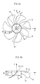
- Figs. 6a and 6b are plan and side views, showing the shape of the blades included in the axial flow fan according to the primary embodiment of this invention.
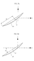
- Figs. 7a and 7b are sectional views, showing the shape of a blade included in the axial flow fan according to the primary embodiment of this invention.
- a hub 53 is firmly mounted to the rotating shaft 52 of the motor 51, with a plurality of blades 55 regularly fixed around the hub 53.
- the fan housing 57 covers the blades 55 so as to protect the blades 55 from external impact.
- the axial flow fan of this invention is optimally designed in the axial height of both the blades 55 and the fan housing 57, the number of blades 55, diameter ratio of the inner diameter ID of the fan to the outer diameter OD, camber ratio, pitch angle and sweep angle of the blades 55, thus being reduced in operational noise in addition to being increased in air volume.
- the axial height of the blades 55 is designed to be higher than that of the fan housing 57 as best seen in Fig. 5, and so the leading surface of the blades 55 is placed outside the surface of the housing 57 at a position higher than the housing 57 by a predetermined projection height P. Therefore, the radially sucked air volume of the blades 55 is increased by the projection height P of the blades 55, and so the axial flow fan of this invention desirably increases its air volume.
- the axial flow fan of this invention it is preferable for the axial flow fan of this invention to have eight blades 55 since the eight blades 55 are capable of desirably reducing the operational noise in addition to having an increase in air volume.
- the diameter ratio of the inner diameter ID of the axial flow fan to the outer diameter OD is preferably set to 0.40 ⁇ 0.45, with the inner diameter ID being equal to the diameter of the hub 53.
- the axial height S of the fan housing 57 is 21.0 ⁇ 0.4 mm, while the inner diameter Q of the fan housing 57 is 88.5 ⁇ 0.2 mm.
- the projection height P of the blades 55 from the surface of the fan housing 57 is 4.5 ⁇ 0.1 mm. Therefore, the total height of the axial flow fan according to the primary embodiment is 25.5 ⁇ 0.5 mm, calculated by an addition of the axial height S of the fan housing 57 to the projection height P of the blades 55.
- the outer diameter OD of the blades 55 is 86 ⁇ 0.5 mm, while the inner diameter ID of the blades 55 (the diameter of the hub 53) is 35 ⁇ 0.5 mm. Therefore, the diameter ratio of the blades 55 (the ratio of the inner diameter ID to the outer diameter OD of the blades 55) is 0.407.
- the front leading distance FD of the blades 55 is 14.0 ⁇ 0.4 mm, while the rear trailing distance RD of the blades 55 is 4.94 ⁇ 0.4 mm.
- the front leading distance FD of the blades 55 forms a rotating axis extending from the center point (0, 0, 0) of a blade dater to the maximum blade leading edge RE
- the rear trailing distance RD of the blades 55 forms a rotating axis extending from the center point (0, 0, 0) of the blade dater to the maximum blade trailing edge TE. That is, the two distances ED and RD are commonly defined on the rotating axis (Z-axis) of the hub 53.
- the center point (0, 0, 0) of the blade dater is positioned in the hub 53 and means the center point of the blade tips BT.
- the maximum camber position CP of each blade 55 is set to 0.65 ⁇ 0.7, with the camber positions being uniformly distributed on each blade 55 from the blade hub BH to the blade tip BT.
- the maximum camber ratio of each blade 55 is 3.7 ⁇ 4.1% at the blade hub BH and 9.7 ⁇ 10.1% at the blade tip BT while accomplishing a linear distribution on the blade 55.
- the maximum camber position CP of each blade 55 is located at a point at which the edge of the blade 55 is spaced furthest from a straight line extending from the blade leading edge RE to the blade trailing edge TE.
- the distance between said straight line and said point on each blade 55 is the maximum camber C.
- the maximum camber ratio is a ratio of the maximum camber C to the cord length CL.
- the cord length CL is the length of the straight line extending from the blade leading edge RE to the blade trailing edge TE.
- the pitch angle ⁇ of each blade 55 is 39.0° ⁇ 40.0° at the blade hub BH and 26.0° ⁇ 27.0° at the blade tip BT while being linearly distributed on the blade 55 from the blade hub BH to the blade tip BT.
- the pitch angle ⁇ of each blade 55 is an angle formed between the X-axis and a straight line extending between the blade leading edge RE to the blade trailing edge TE. That is, the pitch angle ⁇ of each blade 55 expresses the slope of the blade 55 relative to a plane perpendicular to the Z-axis.
- the sweep angle ⁇ of each blade 55 is 0.0° at the blade hub BH and 34.0° at the blade tip BT while being quadratic-parabolically distributed on the blade 55 from the blade hub BH to the blade tip BT.
- the above sweep angle ⁇ of each blade 55 is an angle formed between the Y-axis and a straight line extending between the center of the blade hub BH and the blade tip BT, with the center of the blade hub BH being positioned on the Y-axis. That is, the sweep angle ⁇ of each blade 55 expresses the tilt of the blade 55 in the rotating direction of the blades 55.
- the axial height of the blades 55 is designed to be higher than that of the fan housing 57 so as to allow the surface of the blades 55 to be projected from the surface of the housing 57 as described above, the radially sucked air volume of the blades 55 is increased by the projection height of the blades 55.
- the axial flow fan of this invention thus desirably increases its air volume and reduces its operational noise.
- the fan when the axial flow fan of this invention has a high sweep angle ⁇ , a high pitch angle ⁇ and a high camber ratio, the fan desirably reduces its operational noise and has a wide blade width BD capable of increasing the air volume.
- the blade interval between the blades 55 is set to 2.5 mm at the position ⁇ , 5.0 mm at the position ⁇ , 7.0 mm at the position ⁇ , and 17.0 mm at the position ⁇ as shown in Fig. 6a.
- the blade interval is primarily set to 2.5 ⁇ 0.5 mm at a position around the blade hub BH.
- the blade interval within the first positional section of 0 ⁇ 0.75 is quadratic-parabolically increased from 2.5 ⁇ 0.5 mm to 5.0 ⁇ 0.5 mm.
- the blade interval within the second positional section of 0.75 ⁇ 0.97 is quadratic-parabolically increased from 5.0 ⁇ 0.5 mm to 7.0 ⁇ 0.5 mm.
- the blade interval is cubic-parabolically increased from 7.0 ⁇ 0.5 mm to 17.0 ⁇ 1.0 mm.
- the blade intervals of 5.0 mm and 7.0 mm are located at the positions of 0.75 and 0.97 of the extent from the blade hub BH to the blade tip BT.
- the differentially derived function at the boundary points of 0.75 and 0.97 between the three sections is zero, while the blade interval distribution within the three sections forms quadratic and cubic-parabolic distributions.
- the axial height S of the fan housing it is most preferable to set the axial height S of the fan housing to 21.0 mm, the inner diameter Q of the fan housing to 88.5 ⁇ 0.2 mm, and the projection height P of the blades from the surface of the fan housing to 4.5 ⁇ 0.1 mm.
- the outer diameter OD of the blades is also most preferable to set the outer diameter OD of the blades to 86 mm, the inner diameter ID of the blades to 35 mm, the front leading distance FD of the blades to 14.0 ⁇ 0.4 mm, the rear trailing distance RD of the blades to 4.94 ⁇ 0.4 mm, and the number of blades to eight.
- the maximum camber position CP of each blade it is most preferable to set the maximum camber position CP of each blade to 0.67 while uniformly distributing the camber positions on each blade 55 from the blade hub BH to the blade tip BT.
- the maximum camber ratio of each blade 55 is most preferably set to 3.8% at the blade hub BH and 9.89% at the blade tip BT while accomplishing a linear distribution on the blade 55.
- the sweep angle ⁇ of each blade 55 is most preferably set to 0.0° at the blade hub BH and 34.0° at the blade tip BT while accomplishing a quadratic-parabolic distribution on the blade 55 from the blade hub BH to the blade tip BT.
- the pitch angle ⁇ of each blade 55 is most preferably set to 39.65° at the blade hub BH and to 26.65° at the blade tip BT while accomplishing linear distribution on the blade 55 from the blade hub BH to the blade tip BT.
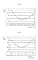
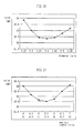
- Fig. 8 is a graph showing the operational noise of the axial flow fan as a function of the diameter ratio (ID/OD) of the blades 55. This graph shows that it is possible to accomplish a desired minimum operational noise of 22.4dB ⁇ 0.1 when the diameter ratio of the blades 55 is set to 0.4 ⁇ 0.45.
- Fig. 9 is a graph showing the operational noise of the axial flow fan as a function of the maximum camber ratio of the axial flow fan. This graph shows that it is possible to accomplish a desired low operational noise of 22.6dB ⁇ 0.1 when the maximum camber ratio of each blade 55 is set to 3.7 ⁇ 4.1% at the blade hub BH and to 9.7 ⁇ 10.1% at the blade tip BT while accomplishing a linear distribution on the blade 55. Particularly, this graph shows that when the maximum camber ratio of each blade 55 is set to 4.0% at the blade hub BH and to 10.0% at the blade tip BT while accomplishing a linear distribution on the blade 55, the desired minimum operational noise of 22.5dB is accomplished.
- Fig. 10 is a graph showing the operational noise of the axial flow fan as a function of the pitch angle ⁇ of the blades 55. This graph shows that it is possible to accomplish a desired minimum operational noise of 22.5dB ⁇ 0.1 when the pitch angle ⁇ of each blade 55 is set to 39.0° ⁇ 40.0° at the blade hub BH and to 26.0° ⁇ 27.0° at the blade tip BT while accomplishing a linear distribution on the blade 55 from the blade hub BH to the blade tip BT.
- Fig. 11 is a graph showing operational noise of the axial flow fan as a function of sweep angle ⁇ of the blades 55. This graph shows that it is possible to accomplish a desired minimum operational noise of 22.6dB when the sweep angle ⁇ of each blade 55 is set to 0.0° at the blade hub BH and to 34.0° at the blade tip BT while accomplishing a quadratic-parabolic distribution on the blade 55 from the blade hub BH to the blade tip BT.
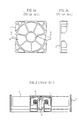
- Figs. 12a and 12b are plan and side views of an axial flow fan with a BLDC motor in accordance with the second embodiment of the present invention.
- Fig. 13 is a sectional view taken along the line C-C of Fig. 12a, showing the construction of the axial flow fan according to the second embodiment of this invention.
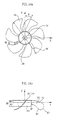
- Figs. 14a and 14b are plan and side views, showing the shape of the blades included in the axial flow fan according to the second embodiment of this invention.
- Figs. 15a and 15b are sectional views, showing the shape of a blade included in the axial flow fan according to the second embodiment of this invention.
- a hub 153 is firmly mounted to the rotating shaft 152 of the motor 151, with a plurality of blades 155 regularly fixed around the hub 153.
- the fan housing 157 is connected to a duct 160 and covers the blades 155 so as to protect the blades 155 from external impact.
- the axial flow fan of this embodiment is optimally designed in the number of blades 155, diameter ratio of the inner diameter of the fan to the outer diameter, camber ratio, pitch angle ⁇ and sweep angle ⁇ of the blades 155, thus being reduced in operational noise in addition to being increased in air volume.
- the axial flow fan of this embodiment prefferably has seven blades 155, with the diameter ratio of the inner diameter ID' of the blades 155 to the outer diameter OD' being preferably set to 0.40 ⁇ 0.43.
- the axial height S' of the fan housing 157 is set to 25.0 ⁇ 0.5 mm, while the inner diameter Q' of the fan housing 157 is set to 88.5 ⁇ 0.2 mm.
- the outer diameter OD' of the blades 155 is set to 86.5 ⁇ 0.5 mm, while the inner diameter ID' of the blades 155 is set to 35 ⁇ 0.5 mm.
- the front leading distance FD' of the blades 155 is set to 11.51 ⁇ 0.4 mm, while the rear trailing distance RD' of the blades 155 is set to 6.53 ⁇ 0.4 mm.
- the blade width BD' defined by both the front leading distance FD' and the rear trailing distance RD' of the blades 155, is 18.04 ⁇ 0.5 mm.
- the height T of the blades 155 is set to 23.5 ⁇ 0.5 mm.
- the maximum camber position CP' of each blade 155 is set to 0.66 ⁇ 0.69, with the camber positions being uniformly distributed on each blade 155 from the blade hub BH' to the blade tip BT'.
- the maximum camber ratio of each blade 155 is set to 5.3 ⁇ 5.7% at the blade hub BH' and to 11.3 ⁇ 11.7% at the blade tip BT' while accomplishing a linear distribution on the blade 55 from the blade hub BH' to the blade tip BT'.
- the pitch angle ⁇ ' of each blade 155 is set to 37.0° ⁇ 39.0° at the blade hub BH' and to 24.0° ⁇ 26.0° at the blade tip BT' while being linearly distributed on the blade 155 from the blade hub BH' to the blade tip BT'.
- the sweep angle ⁇ ' of each blade 155 is set to 0.0° at the blade hub BH' and to 37.0° at the blade tip BT' while accomplishing a quadratic-parabolic distribution on the blade 155 from the blade hub BH' to the blade tip BT'.
- the fan desirably reduces its operational noise and has a wide blade width BD' capable of increasing the air volume.
- the blade interval between the blades 155 is set to 2.5 mm at the position ⁇ , 5.0 mm at the position ⁇ , 5.5 mm at the position ⁇ , and 17.0 mm at the position ⁇ as shown in Fig. 14a.
- the blade interval is set to 2.5 ⁇ 0.5 mm at a position around the blade hub BH'.
- the blade interval within the first positional section of 0 ⁇ 0.8 is quadratic-parabolically increased from 2.5 ⁇ 0.5 mm to 5.0 ⁇ 0.5 mm.
- the blade interval within the second positional section of 0.8 ⁇ 0.97 is quadratic-parabolically increased from 5.0 ⁇ 0.5 mm to 5.5 ⁇ 0.5 mm.
- the blade interval is cubic-parabolically increased from 5.5 ⁇ 0.5 mm to 17.0 ⁇ 1.0 mm.
- the blade intervals of 5.0 mm and 5.5 mm are located at the positions of 0.8 and 0.97 of the extent from the blade hub BH' to the blade tip BT'.
- the differentially derived function at the boundary points of 0.8 and 0.97 between the three sections is zero, while the blade interval distribution within the three sections forms quadratic and cubic-parabolic distributions.
- the size of the fan in the axial flow fan with a BLDC motor in accordance with the second embodiment of this invention, it is most preferable to set the size of the fan to 92mm(W) x 92mm(D) x 25mm(H), the axial height S' of the fan housing to 25.0 mm, and the inner diameter Q' of the fan housing to 88.5 mm.
- the height of the blades is 23.5 mm, the front leading distance FD' of the blades to 11.51 mm, the rear trailing distance RD' of the blades to 6.53 mm, the blade width BD' to 18.04 mm, and the number of blades to seven.
- the maximum camber position CP' of each blade it is most preferable to set the maximum camber position CP' of each blade to 0.67 while uniformly distributing the camber positions on each blade 155 from the blade hub BH' to the blade tip BT'.
- the maximum camber ratio of each blade 155 is most preferably set to 5.47% at the blade hub BH' and 11.47% at the blade tip BT' while accomplishing a linear distribution on the blade 55 from the blade hub BH' to the blade tip BT'.
- the sweep angle ⁇ ' of each blade 155 is most preferably set to 0.0° at the blade hub BH' and to 37.0° ⁇ 38.0° at the blade tip BT' while accomplishing a quadratic-parabolic distribution on the blade 155 from the blade hub BH' to the blade tip BT'.
- the pitch angle ⁇ ' of each blade 155 is most preferably set to 37.74° at the blade hub BH' and to 24.74° at the blade tip BT' while accomplishing linear distribution on the blade 155 from the blade hub BH' to the blade tip BT'.
- Fig. 16 is a graph showing the operational noise of the axial flow fan as a function of the diameter ratio (ID'/OD') of the blades 155. This graph shows that it is possible to accomplish a desired minimum operational noise of 22.4dB ⁇ 0.1 when the diameter ratio of the blades 155 is set to 0.4 ⁇ 0.45.
- Fig. 17 is a graph showing the operational noise of the axial flow fan as a function of the maximum camber ratio of the axial flow fan. This graph shows that it is possible to accomplish a desired low operational noise of 22.4dB when the maximum camber ratio of each blade 155 is set to 5.3 ⁇ 5.7% at the blade hub BH' and to 11.3 ⁇ 11.7% at the blade tip BT' while accomplishing a linear distribution on the blade 155 from the blade hub BH' to the blade tip BT'.
- Fig. 18 is a graph showing the operational noise of the axial flow fan as a function of the pitch angle ⁇ ' of the blades 155. This graph shows that it is possible to accomplish a desired minimum operational noise of 22.4dB when the pitch angle ⁇ ' of each blade 155 is set to 37.0° ⁇ 39.0° at the blade hub BH' and to 24.0° ⁇ 26.0° at the blade tip BT' while accomplishing a linear distribution on the blade 155 from the blade hub BH' to the blade tip BT'.
- Fig. 19 is a graph showing operational noise of the axial flow fan as a function of the sweep angle ⁇ ' of the blades 155. This graph shows that it is possible to accomplish a desired minimum operational noise of 22.5dB ⁇ 0.1 when the sweep angle ⁇ ' of each blade 155 is set to 0.0° at the blade hub BH' and to 37.0° ⁇ 38.0° at the blade tip BT' while accomplishing a quadratic-parabolic distribution on each blade 155 from the blade hub BH' to the blade tip BT'.
- the present invention provides an axial flow fan with a BLDC motor for electronic appliances, such as office or domestic electronic appliances.
- the axial flow fan of this invention is optimally designed in axial height of both the blades and the fan housing, the number of blades, diameter ratio of the inner diameter to the outer diameter of the blades, camber ratio, pitch angle and sweep angle of the blades, thus being reduced in operational noise in addition to being increased in air volume.
- the axial flow fan of this invention when used in electronic appliances, such as office or domestic electronic appliances, it is possible to reduce operational noise of the appliances in addition to accomplishing an increase in air volume.
Landscapes
- Engineering & Computer Science (AREA)
- Mechanical Engineering (AREA)
- General Engineering & Computer Science (AREA)
- Physics & Mathematics (AREA)
- Fluid Mechanics (AREA)
- Structures Of Non-Positive Displacement Pumps (AREA)
- Connection Of Motors, Electrical Generators, Mechanical Devices, And The Like (AREA)
Abstract
Description
| Blade Width = 18. 95mm | ||
| X | Y | Z |
| 5.526 | 16.605 | -4.580 |
| 4.352 | 16.950 | -3.810 |
| 3.172 | 17.210 | -3.003 |
| 1.993 | 17.386 | -2.164 |
| 0.821 | 17.481 | -1.298 |
| -0.339 | 17.497 | 0.409 |
| -1.481 | 17.437 | 0.498 |
| -2.599 | 17.306 | 1.422 |
| -3.652 | 17.115 | 2.404 |
| -4.628 | 16.877 | 3.457 |
| -5.526 | 16.605 | 4.580 |
| -6.003 | 19.130 | 4.863 |
| -6.292 | 21.706 | 4.941 |
| -6.384 | 24.326 | 4.808 |
| -6.261 | 26.983 | 4.461 |
| -5.903 | 29.668 | 3.907 |
| -5.280 | 32.372 | 3.159 |
| -4.219 | 35.097 | 2.146 |
| -2.622 | 37.809 | 0.884 |
| -0.463 | 40.447 | -0.544 |
| 5.960 | 42.585 | -6.394 |
| 7.397 | 42.359 | -7.669 |
| 8.967 | 42.055 | -8.651 |
| 10.602 | 41.673 | -9.468 |
| 12.257 | 41.216 | -10.200 |
| 13.902 | 40.691 | -10.902 |
| 15.548 | 40.091 | -11.542 |
| 17.190 | 39.415 | -12.119 |
| 18.824 | 38.661 | -12.634 |
| 20.446 | 37.828 | -13.083 |
| 22.051 | 36.915 | -13.466 |
| 23.278 | 33.080 | -13.770 |
| 20.305 | 32.002 | -13.074 |
| 17.511 | 30.708 | -12.119 |
| 14.886 | 29.228 | -10.947 |
| 12.479 | 27.556 | -9.647 |
| 10.415 | 25.667 | -8.369 |
| 8.695 | 23.599 | -7.179 |
| 7.310 | 21.385 | -6.126 |
| 6.255 | 19.049 | -5.250 |
| 5.526 | 16.605 | -4.580 |
| Blade Width =18. 04 m | ||
| X | Y | Z |
| 6.448 | 16.269 | -4.991 |
| 4.900 | 16.800 | -4.144 |
| 3.339 | 17.179 | -3.223 |
| 1.780 | 17.409 | -2.241 |
| 0.238 | 17.498 | -1.209 |
| -1.276 | 17.483 | -0.134 |
| -2.749 | 17.283 | 0.972 |
| -4.129 | 17.006 | 2.164 |
| -5.362 | 16.658 | 3.503 |
| -6.448 | 16.269 | 4.991 |
| -7.159 | 19.061 | 5.809 |
| -7.570 | 21.954 | 6.326 |
| -7.664 | 24.932 | 6.531 |
| -7.410 | 27.980 | 6.425 |
| -6.774 | 31.076 | 6.026 |
| -5.715 | 34.192 | 5.370 |
| -4.116 | 37.301 | 4.469 |
| -1.868 | 40.346 | 3.377 |
| 5.734 | 42.868 | -2.467 |
| 7.366 | 42.618 | -5.253 |
| 9.738 | 42.140 | -6.359 |
| 12.075 | 41.530 | -7.459 |
| 14.448 | 40.765 | -8.370 |
| 16.798 | 39.855 | -9.200 |
| 19.128 | 38.790 | -9.912 |
| 21.429 | 37.568 | -10.495 |
| 23.687 | 36.187 | -10.950 |
| 25.888 | 34.646 | -11.273 |
| 26.628 | 30.368 | -11.436 |
| 22.781 | 29.822 | -10.981 |
| 19.222 | - 28.849 | -10.189 |
| 16.020 | 27.477 | -9.191 |
| 13.248 | 25.735 | -8.132 |
| 10.908 | 23.693 | -7.109 |
| 8.998 | 21.408 | -6.203 |
| 7.513 | 18.924 | -5.480 |
| 6.448 | 16.269 | -4.991 |
Claims (12)
- An axial flow fan, comprising a brushless direct current motor, a hub mounted to a rotating shaft of said motor, a plurality of blades mounted to said hub, and a fan housing covering said blades while holding the motor therein, wherein
said blades have an axial height higher than that of said fan housing, with a leading surface of said blades being placed outside a surface of said fan housing at a position higher than the surface of the fan housing by a predetermined projection height, thus increasing an air volume of the fan. - The axial flow fan according to claim 1, wherein an axial height of the said housing is 21.0 ± 0.4 mm, while the projection height of said blades from the surface of the fan housing is 4.5 ± 0.1 mm.
- An axial flow fan, comprising a brushless direct current motor, a hub mounted to a rotating shaft of said motor, a plurality of blades mounted to said hub, and a fan housing covering said blades while holding the motor therein, wherein
the number of said blades is eight, with a diameter ratio of an inner diameter to an outer diameter of the fan being 0.40 ∼ 0.45, thus reducing operational noise of the fan. - The axial flow fan according to claim 3, wherein said outer diameter is 86 ± 0.5 mm, while the inner diameter is 35 ± 0.5 mm, with a front leading distance of the blades being 14.0 ± 0.4 mm and a rear trailing distance of the blades being 4.94 ± 0.4 mm.
- The axial flow fan according to claim 3, wherein a maximum camber position of each of the blades is 0.65 ∼ 0.7 while accomplishing a uniform distribution on the blade from a blade hub to a blade tip, and a maximum camber ratio of each of the blades is 3.7 ∼ 4.1% at said blade hub and 9.7 ∼ 10.1% at said blade tip while accomplishing a linear distribution on the blade.
- The axial flow fan according to claim 3, wherein a pitch angle of each of the blades is 39.0° ∼ 40.0° at a blade hub and 26.0° ∼ 27.0° at a blade tip while accomplishing a linear distribution on the blade from the blade hub to the blade tip.
- The axial flow fan according to claim 3, wherein a sweep angle of each of the blades is 0.0° at a blade hub and 34.0° at a blade tip while accomplishing a quadratic-parabolic distribution on the blade from the blade hub to the blade tip.
- An axial flow fan, comprising a brushless direct current motor, a hub mounted to a rotating shaft of said motor, a plurality of blades mounted to said hub, and a fan housing covering said blades while holding the motor therein, wherein
the number of said blades is seven, with a diameter ratio of an inner diameter to an outer diameter of the fan being 0.40 ∼ 0.43, thus reducing operational noise of the fan. - The axial flow fan according to claim 8, wherein said outer diameter is 86.5 ± 0.5 mm, while the inner diameter is 35 ± 0.5 mm, with a front leading distance of the blades being 11.51 ± 0.4 mm and a rear trailing distance of the blades being 6.53 ± 0.4 mm.
- The axial flow fan according to claim 8, wherein a maximum camber position of each of the blades is 0.66 ∼ 0.69 while accomplishing a uniform distribution on the blade from a blade hub to a blade tip, and a maximum camber ratio of each of the blades is 5.3 ∼ 5.7% at said blade hub and 11.3 ∼ 11.7% at said blade tip while accomplishing a linear distribution on the blade.
- The axial flow fan according to claim 8, wherein a pitch angle of each of the blades is 37.0° ∼ 39.0° at a blade hub and 24.0° ∼ 26.0° at a blade tip while accomplishing a linear distribution on the blade from the blade hub to the blade tip.
- The axial flow fan according to claim 8, wherein a sweep angle of each of the blades is 0.0° at a blade hub and 37.0° at a blade tip while accomplishing a quadratic-parabolic distribution on the blade from the blade hub to the blade tip.
Priority Applications (5)
| Application Number | Priority Date | Filing Date | Title |
|---|---|---|---|
| US09/590,693 US6544010B1 (en) | 2000-06-09 | 2000-06-09 | Axial flow fan with brushless direct current motor |
| JP2000182341A JP4662608B2 (en) | 2000-06-09 | 2000-06-13 | Fan motor with integrated axial fan and motor |
| DE2000634932 DE60034932T2 (en) | 2000-06-13 | 2000-06-13 | Axial fan with brushless DC motor |
| EP00112531A EP1164295B1 (en) | 2000-06-09 | 2000-06-13 | Axial flow fan with brushless direct current motor |
| CNB001186892A CN1199011C (en) | 2000-06-09 | 2000-06-21 | Axial fans with brushless DC motors |
Applications Claiming Priority (4)
| Application Number | Priority Date | Filing Date | Title |
|---|---|---|---|
| US09/590,693 US6544010B1 (en) | 2000-06-09 | 2000-06-09 | Axial flow fan with brushless direct current motor |
| JP2000182341A JP4662608B2 (en) | 2000-06-09 | 2000-06-13 | Fan motor with integrated axial fan and motor |
| EP00112531A EP1164295B1 (en) | 2000-06-09 | 2000-06-13 | Axial flow fan with brushless direct current motor |
| CNB001186892A CN1199011C (en) | 2000-06-09 | 2000-06-21 | Axial fans with brushless DC motors |
Publications (2)
| Publication Number | Publication Date |
|---|---|
| EP1164295A1 true EP1164295A1 (en) | 2001-12-19 |
| EP1164295B1 EP1164295B1 (en) | 2007-05-23 |
Family
ID=27429892
Family Applications (1)
| Application Number | Title | Priority Date | Filing Date |
|---|---|---|---|
| EP00112531A Expired - Lifetime EP1164295B1 (en) | 2000-06-09 | 2000-06-13 | Axial flow fan with brushless direct current motor |
Country Status (4)
| Country | Link |
|---|---|
| US (1) | US6544010B1 (en) |
| EP (1) | EP1164295B1 (en) |
| JP (1) | JP4662608B2 (en) |
| CN (1) | CN1199011C (en) |
Cited By (6)
| Publication number | Priority date | Publication date | Assignee | Title |
|---|---|---|---|---|
| EP2212562A4 (en) * | 2007-10-25 | 2011-03-16 | Lg Electronics Inc | Fan |
| CN106762724A (en) * | 2016-12-01 | 2017-05-31 | 武汉通畅汽车电子照明有限公司 | Small modular heat abstractor |
| CN107191403A (en) * | 2017-05-16 | 2017-09-22 | 北京小米移动软件有限公司 | Control method, device and the fan of oscillating fan rotational angle |
| CN108561320A (en) * | 2018-05-24 | 2018-09-21 | 中国农业大学 | A kind of agricultural fan with the long blade width ratio of optimal kuppe |
| CN109236715A (en) * | 2018-11-14 | 2019-01-18 | 成都工业学院 | A kind of axial-flow fan blade regulating mechanism and blower |
| WO2020008163A1 (en) * | 2018-07-05 | 2020-01-09 | Dyson Technology Limited | Axial impeller |
Families Citing this family (26)
| Publication number | Priority date | Publication date | Assignee | Title |
|---|---|---|---|---|
| CN1314901C (en) * | 2003-05-14 | 2007-05-09 | 台达电子工业股份有限公司 | Axial flow fan |
| JP2007506037A (en) * | 2004-03-01 | 2007-03-15 | ブリュニク,マシアス | Propeller blower and shell propeller |
| JP4745626B2 (en) * | 2004-06-29 | 2011-08-10 | ループウイング株式会社 | Axial flow blower |
| TWI273175B (en) * | 2004-08-27 | 2007-02-11 | Delta Electronics Inc | Fan |
| TWI305612B (en) * | 2004-08-27 | 2009-01-21 | Delta Electronics Inc | Heat-dissipating fan |
| CN100455822C (en) * | 2004-09-06 | 2009-01-28 | 台达电子工业股份有限公司 | Heat dissipation fan and fan frame structure thereof |
| CN100510425C (en) * | 2004-09-08 | 2009-07-08 | 台达电子工业股份有限公司 | Fan with cooling device |
| DE102005005977A1 (en) * | 2005-02-09 | 2006-08-10 | Behr Gmbh & Co. Kg | Axial |
| CN1904492B (en) * | 2005-07-30 | 2010-10-06 | 乐金电子(天津)电器有限公司 | Ceiling-type air conditioner and flow path structure of the ceiling-type air conditioner |
| US20070243064A1 (en) * | 2006-04-12 | 2007-10-18 | Jcs/Thg,Llc. | Fan blade assembly for electric fan |
| JP2008014302A (en) * | 2006-06-09 | 2008-01-24 | Nippon Densan Corp | Axial flow fan |
| CA2598867A1 (en) * | 2007-07-31 | 2009-01-31 | Ghislain Lauzon | Fan muffler |
| WO2010081294A1 (en) * | 2009-01-14 | 2010-07-22 | Qin Biao | Axial-flow type electronic radiator fan |
| US8360719B2 (en) * | 2009-01-16 | 2013-01-29 | Delta Electronics, Inc. | Fan |
| JP5849524B2 (en) | 2011-08-19 | 2016-01-27 | 日本電産株式会社 | Axial flow fan |
| IN2014CN03317A (en) * | 2011-11-10 | 2015-07-03 | Mitsubishi Electric Corp | |
| CN104214139B (en) * | 2013-05-30 | 2016-12-28 | 台达电子工业股份有限公司 | fan |
| US10208770B2 (en) * | 2014-02-24 | 2019-02-19 | Mitsubishi Electric Corporation | Axial flow fan |
| CN104832442B (en) * | 2015-02-01 | 2018-04-10 | 昆明奥图环保设备股份有限公司 | A kind of very-long-range with function of increasing pressure penetrates mist depositing dust air cleaning facility |
| JP6928434B2 (en) * | 2016-09-30 | 2021-09-01 | ミネベアミツミ株式会社 | Axial fan device |
| CN108716473B (en) * | 2018-03-02 | 2020-12-29 | 青岛海信日立空调系统有限公司 | Axial flow fan and air conditioner outdoor unit |
| CN110259706A (en) * | 2018-03-12 | 2019-09-20 | 加诺有限公司 | Radiator fan |
| CN112128124A (en) * | 2020-09-28 | 2020-12-25 | 西南电子技术研究所(中国电子科技集团公司第十研究所) | Air-cooled heat dissipation axial flow cooling fan for electronic equipment |
| US11536279B1 (en) * | 2022-03-07 | 2022-12-27 | Stokes Technology Development Ltd. | Thin type counter-rotating axial air moving device |
| CN114922862A (en) * | 2022-05-24 | 2022-08-19 | 沈阳兴华航空电器有限责任公司 | Fan capable of reducing noise |
| JP7483171B1 (en) * | 2023-06-12 | 2024-05-14 | 三菱電機株式会社 | Impellers, blowers and air conditioners |
Citations (6)
| Publication number | Priority date | Publication date | Assignee | Title |
|---|---|---|---|---|
| US1907727A (en) * | 1929-05-06 | 1933-05-09 | Ilg Electric Ventilating Compa | Ventilator |
| DE9002321U1 (en) * | 1989-03-02 | 1990-05-03 | Süd-Electric GmbH, 8011 Kirchseeon | fan |
| US5135363A (en) * | 1982-11-09 | 1992-08-04 | Papst-Motoren Gmbh & Co. Kg | Miniaturized direct current fan |
| US5695318A (en) * | 1991-08-15 | 1997-12-09 | Papst-Motoren Gmbh & Co Kg | Diagonal fan |
| US5910045A (en) * | 1995-09-07 | 1999-06-08 | Daikin Industries, Ltd. | Air discharge unit for underfloor air conditioning and underfloor air conditioning system using same |
| DE29903937U1 (en) * | 1998-09-23 | 1999-06-10 | Delta Electronics, Inc., Taoyuan | Improved fan design |
Family Cites Families (28)
| Publication number | Priority date | Publication date | Assignee | Title |
|---|---|---|---|---|
| US2583374A (en) * | 1950-10-18 | 1952-01-22 | Hydraulic Supply Mfg Company | Exhaust fan |
| US4055113A (en) * | 1976-05-07 | 1977-10-25 | Robbins & Myers, Inc. | Ventilator apparatus |
| JPS60114300U (en) * | 1984-12-13 | 1985-08-02 | トリン コーポレーシヨン | axial flow wheel |
| JPS6361800A (en) * | 1986-09-01 | 1988-03-17 | Seiko Electronic Components Ltd | Axial fan |
| JPH0772559B2 (en) * | 1988-12-26 | 1995-08-02 | 株式会社東芝 | Axial fan structure |
| JPH02298697A (en) * | 1989-05-12 | 1990-12-11 | Matsushita Electric Ind Co Ltd | Blower device |
| JPH0360883U (en) * | 1989-10-03 | 1991-06-14 | ||
| JP3082378B2 (en) * | 1991-12-20 | 2000-08-28 | 株式会社デンソー | Blower fan |
| JPH05202893A (en) * | 1992-01-30 | 1993-08-10 | Matsushita Electric Ind Co Ltd | Blower |
| US5273400A (en) * | 1992-02-18 | 1993-12-28 | Carrier Corporation | Axial flow fan and fan orifice |
| JPH0610892A (en) * | 1992-06-30 | 1994-01-21 | Hitachi Ltd | Axial blower and air conditioner using the same |
| JP2753182B2 (en) * | 1992-09-29 | 1998-05-18 | 松下精工株式会社 | Axial fan |
| US5320493A (en) * | 1992-12-16 | 1994-06-14 | Industrial Technology Research Institute | Ultra-thin low noise axial flow fan for office automation machines |
| JP3467815B2 (en) * | 1993-12-17 | 2003-11-17 | 株式会社デンソー | Electric fan |
| JPH06336999A (en) * | 1993-03-30 | 1994-12-06 | Nippondenso Co Ltd | Axial fan |
| JPH0783191A (en) * | 1993-09-14 | 1995-03-28 | Tanashin Denki Co | Axial fan |
| JP2825220B2 (en) * | 1995-03-10 | 1998-11-18 | 日本サーボ株式会社 | Axial fan |
| JP2744771B2 (en) * | 1995-05-31 | 1998-04-28 | 山洋電気株式会社 | Blowers and blowers for cooling electronic components |
| US5577888A (en) * | 1995-06-23 | 1996-11-26 | Siemens Electric Limited | High efficiency, low-noise, axial fan assembly |
| JPH1089289A (en) * | 1996-09-13 | 1998-04-07 | Ebara Corp | Impeller for axial flow blower |
| JPH10176694A (en) * | 1996-12-18 | 1998-06-30 | Nec Corp | Fan |
| JPH11230092A (en) * | 1998-02-12 | 1999-08-24 | Japan Servo Co Ltd | Axial fan |
| JPH11324985A (en) * | 1998-05-19 | 1999-11-26 | Japan Servo Co Ltd | Axial flow fan |
| US5957661A (en) * | 1998-06-16 | 1999-09-28 | Siemens Canada Limited | High efficiency to diameter ratio and low weight axial flow fan |
| JP3926036B2 (en) * | 1998-07-10 | 2007-06-06 | 株式会社東芝 | Fan motor |
| US6129528A (en) * | 1998-07-20 | 2000-10-10 | Nmb Usa Inc. | Axial flow fan having a compact circuit board and impeller blade arrangement |
| GB2344855B (en) * | 1998-12-14 | 2002-10-09 | Sunonwealth Electr Mach Ind Co | Miniature heat dissipating fans with minimized thickness |
| JP3682397B2 (en) * | 2000-02-28 | 2005-08-10 | 株式会社東芝 | Fan motor |
-
2000
- 2000-06-09 US US09/590,693 patent/US6544010B1/en not_active Expired - Fee Related
- 2000-06-13 JP JP2000182341A patent/JP4662608B2/en not_active Expired - Fee Related
- 2000-06-13 EP EP00112531A patent/EP1164295B1/en not_active Expired - Lifetime
- 2000-06-21 CN CNB001186892A patent/CN1199011C/en not_active Expired - Fee Related
Patent Citations (6)
| Publication number | Priority date | Publication date | Assignee | Title |
|---|---|---|---|---|
| US1907727A (en) * | 1929-05-06 | 1933-05-09 | Ilg Electric Ventilating Compa | Ventilator |
| US5135363A (en) * | 1982-11-09 | 1992-08-04 | Papst-Motoren Gmbh & Co. Kg | Miniaturized direct current fan |
| DE9002321U1 (en) * | 1989-03-02 | 1990-05-03 | Süd-Electric GmbH, 8011 Kirchseeon | fan |
| US5695318A (en) * | 1991-08-15 | 1997-12-09 | Papst-Motoren Gmbh & Co Kg | Diagonal fan |
| US5910045A (en) * | 1995-09-07 | 1999-06-08 | Daikin Industries, Ltd. | Air discharge unit for underfloor air conditioning and underfloor air conditioning system using same |
| DE29903937U1 (en) * | 1998-09-23 | 1999-06-10 | Delta Electronics, Inc., Taoyuan | Improved fan design |
Cited By (11)
| Publication number | Priority date | Publication date | Assignee | Title |
|---|---|---|---|---|
| EP2212562A4 (en) * | 2007-10-25 | 2011-03-16 | Lg Electronics Inc | Fan |
| US8235672B2 (en) | 2007-10-25 | 2012-08-07 | Lg Electronics Inc. | Fan |
| CN106762724A (en) * | 2016-12-01 | 2017-05-31 | 武汉通畅汽车电子照明有限公司 | Small modular heat abstractor |
| CN107191403A (en) * | 2017-05-16 | 2017-09-22 | 北京小米移动软件有限公司 | Control method, device and the fan of oscillating fan rotational angle |
| CN107191403B (en) * | 2017-05-16 | 2019-02-12 | 北京小米移动软件有限公司 | Method, device and fan for controlling rotation angle of fan swing head |
| US10612554B2 (en) | 2017-05-16 | 2020-04-07 | Beijing Xiaomi Mobile Software Co., Ltd. | Method and device for controlling rotation angle of swinging head of fan, and fan |
| CN108561320A (en) * | 2018-05-24 | 2018-09-21 | 中国农业大学 | A kind of agricultural fan with the long blade width ratio of optimal kuppe |
| CN108561320B (en) * | 2018-05-24 | 2023-11-24 | 中国农业大学 | An agricultural fan with optimal shroud length and blade width ratio |
| WO2020008163A1 (en) * | 2018-07-05 | 2020-01-09 | Dyson Technology Limited | Axial impeller |
| GB2575297B (en) * | 2018-07-05 | 2021-05-19 | Dyson Technology Ltd | An axial impeller |
| CN109236715A (en) * | 2018-11-14 | 2019-01-18 | 成都工业学院 | A kind of axial-flow fan blade regulating mechanism and blower |
Also Published As
| Publication number | Publication date |
|---|---|
| EP1164295B1 (en) | 2007-05-23 |
| US6544010B1 (en) | 2003-04-08 |
| CN1330228A (en) | 2002-01-09 |
| JP2002021798A (en) | 2002-01-23 |
| CN1199011C (en) | 2005-04-27 |
| JP4662608B2 (en) | 2011-03-30 |
Similar Documents
| Publication | Publication Date | Title |
|---|---|---|
| EP1164295B1 (en) | Axial flow fan with brushless direct current motor | |
| JP5097201B2 (en) | Axial fan assembly | |
| US9513021B2 (en) | Blower and heat pump apparatus using the same | |
| JP4099458B2 (en) | Centrifugal fan including stator vanes | |
| KR100934556B1 (en) | Centrifugal fan and air conditioner using it | |
| US20080247868A1 (en) | Fan and impeller thereof | |
| US8172524B2 (en) | Fan including specific stationary vane arrangement | |
| US20050207888A1 (en) | Centrifugal fan and casing thereof | |
| CN1573251A (en) | Turbofan and air conditioner having the turbofan | |
| EP2261511A2 (en) | Centrifugal fan | |
| CN211397958U (en) | Air supply device | |
| US20070140844A1 (en) | Axial Flow Fan | |
| CN101089405A (en) | fan unit | |
| CN104334974B (en) | Air-conditioner outdoor unit | |
| CN110088482B (en) | Multi-blade blower | |
| CN110506164B (en) | Propeller fans and outdoor units for air conditioners | |
| JP2001003899A (en) | Blower, air conditioner and air purifier using the same | |
| EP1326482A2 (en) | Cooling fan for microwave oven | |
| CN216477906U (en) | Tower fan | |
| KR100422704B1 (en) | Axial fan with Auxiliary impeller | |
| CN113167291B (en) | propeller fan | |
| JPH11264567A (en) | Ceiling-mounted air conditioner | |
| KR100381202B1 (en) | An Axial Flow Fan with BLDC Motor | |
| CN221403275U (en) | Air Conditioner | |
| CN113056612B (en) | Propeller fan |
Legal Events
| Date | Code | Title | Description |
|---|---|---|---|
| PUAI | Public reference made under article 153(3) epc to a published international application that has entered the european phase |
Free format text: ORIGINAL CODE: 0009012 |
|
| 17P | Request for examination filed |
Effective date: 20010112 |
|
| AK | Designated contracting states |
Kind code of ref document: A1 Designated state(s): AT BE CH CY DE DK ES FI FR GB GR IE IT LI LU MC NL PT SE Kind code of ref document: A1 Designated state(s): DE GB NL |
|
| AX | Request for extension of the european patent |
Free format text: AL;LT;LV;MK;RO;SI |
|
| AKX | Designation fees paid |
Free format text: DE GB NL |
|
| 17Q | First examination report despatched |
Effective date: 20050209 |
|
| GRAP | Despatch of communication of intention to grant a patent |
Free format text: ORIGINAL CODE: EPIDOSNIGR1 |
|
| GRAS | Grant fee paid |
Free format text: ORIGINAL CODE: EPIDOSNIGR3 |
|
| GRAA | (expected) grant |
Free format text: ORIGINAL CODE: 0009210 |
|
| AK | Designated contracting states |
Kind code of ref document: B1 Designated state(s): DE GB NL |
|
| REG | Reference to a national code |
Ref country code: GB Ref legal event code: FG4D |
|
| REF | Corresponds to: |
Ref document number: 60034932 Country of ref document: DE Date of ref document: 20070705 Kind code of ref document: P |
|
| PLBE | No opposition filed within time limit |
Free format text: ORIGINAL CODE: 0009261 |
|
| STAA | Information on the status of an ep patent application or granted ep patent |
Free format text: STATUS: NO OPPOSITION FILED WITHIN TIME LIMIT |
|
| 26N | No opposition filed |
Effective date: 20080226 |
|
| PGFP | Annual fee paid to national office [announced via postgrant information from national office to epo] |
Ref country code: GB Payment date: 20140513 Year of fee payment: 15 |
|
| PGFP | Annual fee paid to national office [announced via postgrant information from national office to epo] |
Ref country code: NL Payment date: 20140513 Year of fee payment: 15 Ref country code: DE Payment date: 20140513 Year of fee payment: 15 |
|
| REG | Reference to a national code |
Ref country code: DE Ref legal event code: R119 Ref document number: 60034932 Country of ref document: DE |
|
| GBPC | Gb: european patent ceased through non-payment of renewal fee |
Effective date: 20150613 |
|
| REG | Reference to a national code |
Ref country code: NL Ref legal event code: MM Effective date: 20150701 |
|
| PG25 | Lapsed in a contracting state [announced via postgrant information from national office to epo] |
Ref country code: DE Free format text: LAPSE BECAUSE OF NON-PAYMENT OF DUE FEES Effective date: 20160101 Ref country code: NL Free format text: LAPSE BECAUSE OF NON-PAYMENT OF DUE FEES Effective date: 20150701 Ref country code: GB Free format text: LAPSE BECAUSE OF NON-PAYMENT OF DUE FEES Effective date: 20150613 |