EP1164049A1 - Fuel battery mounted motorcycle - Google Patents
Fuel battery mounted motorcycle Download PDFInfo
- Publication number
- EP1164049A1 EP1164049A1 EP01114010A EP01114010A EP1164049A1 EP 1164049 A1 EP1164049 A1 EP 1164049A1 EP 01114010 A EP01114010 A EP 01114010A EP 01114010 A EP01114010 A EP 01114010A EP 1164049 A1 EP1164049 A1 EP 1164049A1
- Authority
- EP
- European Patent Office
- Prior art keywords
- fuel battery
- motorcycle
- floor
- disposed
- fuel
- Prior art date
- Legal status (The legal status is an assumption and is not a legal conclusion. Google has not performed a legal analysis and makes no representation as to the accuracy of the status listed.)
- Granted
Links
Images








Classifications
-
- B—PERFORMING OPERATIONS; TRANSPORTING
- B62—LAND VEHICLES FOR TRAVELLING OTHERWISE THAN ON RAILS
- B62K—CYCLES; CYCLE FRAMES; CYCLE STEERING DEVICES; RIDER-OPERATED TERMINAL CONTROLS SPECIALLY ADAPTED FOR CYCLES; CYCLE AXLE SUSPENSIONS; CYCLE SIDECARS, FORECARS, OR THE LIKE
- B62K11/00—Motorcycles, engine-assisted cycles or motor scooters with one or two wheels
-
- B—PERFORMING OPERATIONS; TRANSPORTING
- B60—VEHICLES IN GENERAL
- B60L—PROPULSION OF ELECTRICALLY-PROPELLED VEHICLES; SUPPLYING ELECTRIC POWER FOR AUXILIARY EQUIPMENT OF ELECTRICALLY-PROPELLED VEHICLES; ELECTRODYNAMIC BRAKE SYSTEMS FOR VEHICLES IN GENERAL; MAGNETIC SUSPENSION OR LEVITATION FOR VEHICLES; MONITORING OPERATING VARIABLES OF ELECTRICALLY-PROPELLED VEHICLES; ELECTRIC SAFETY DEVICES FOR ELECTRICALLY-PROPELLED VEHICLES
- B60L58/00—Methods or circuit arrangements for monitoring or controlling batteries or fuel cells, specially adapted for electric vehicles
- B60L58/30—Methods or circuit arrangements for monitoring or controlling batteries or fuel cells, specially adapted for electric vehicles for monitoring or controlling fuel cells
-
- B—PERFORMING OPERATIONS; TRANSPORTING
- B60—VEHICLES IN GENERAL
- B60L—PROPULSION OF ELECTRICALLY-PROPELLED VEHICLES; SUPPLYING ELECTRIC POWER FOR AUXILIARY EQUIPMENT OF ELECTRICALLY-PROPELLED VEHICLES; ELECTRODYNAMIC BRAKE SYSTEMS FOR VEHICLES IN GENERAL; MAGNETIC SUSPENSION OR LEVITATION FOR VEHICLES; MONITORING OPERATING VARIABLES OF ELECTRICALLY-PROPELLED VEHICLES; ELECTRIC SAFETY DEVICES FOR ELECTRICALLY-PROPELLED VEHICLES
- B60L58/00—Methods or circuit arrangements for monitoring or controlling batteries or fuel cells, specially adapted for electric vehicles
- B60L58/30—Methods or circuit arrangements for monitoring or controlling batteries or fuel cells, specially adapted for electric vehicles for monitoring or controlling fuel cells
- B60L58/32—Methods or circuit arrangements for monitoring or controlling batteries or fuel cells, specially adapted for electric vehicles for monitoring or controlling fuel cells for controlling the temperature of fuel cells, e.g. by controlling the electric load
- B60L58/33—Methods or circuit arrangements for monitoring or controlling batteries or fuel cells, specially adapted for electric vehicles for monitoring or controlling fuel cells for controlling the temperature of fuel cells, e.g. by controlling the electric load by cooling
-
- B—PERFORMING OPERATIONS; TRANSPORTING
- B62—LAND VEHICLES FOR TRAVELLING OTHERWISE THAN ON RAILS
- B62M—RIDER PROPULSION OF WHEELED VEHICLES OR SLEDGES; POWERED PROPULSION OF SLEDGES OR SINGLE-TRACK CYCLES; TRANSMISSIONS SPECIALLY ADAPTED FOR SUCH VEHICLES
- B62M7/00—Motorcycles characterised by position of motor or engine
- B62M7/12—Motorcycles characterised by position of motor or engine with the engine beside or within the driven wheel
-
- Y—GENERAL TAGGING OF NEW TECHNOLOGICAL DEVELOPMENTS; GENERAL TAGGING OF CROSS-SECTIONAL TECHNOLOGIES SPANNING OVER SEVERAL SECTIONS OF THE IPC; TECHNICAL SUBJECTS COVERED BY FORMER USPC CROSS-REFERENCE ART COLLECTIONS [XRACs] AND DIGESTS
- Y02—TECHNOLOGIES OR APPLICATIONS FOR MITIGATION OR ADAPTATION AGAINST CLIMATE CHANGE
- Y02T—CLIMATE CHANGE MITIGATION TECHNOLOGIES RELATED TO TRANSPORTATION
- Y02T90/00—Enabling technologies or technologies with a potential or indirect contribution to GHG emissions mitigation
- Y02T90/40—Application of hydrogen technology to transportation, e.g. using fuel cells
Definitions
- the present invention relates to a fuel battery mounted motorcycle.
- Fuel battery mounted motorcycles are known, for example, from Japanese Patent Laid-open No. Hei 3-109126 entitled "Fuel Battery Mounted motorcycle".
- the above technique discloses an electric motorcar 1 using a fuel battery 13 as an energy source, wherein the fuel battery 13 is disposed in a lower central portion of a vehicular body 2 (note: reference numerals are cited from the document) .
- the motorcycle 1 In the case of using the fuel battery 13 as an energy source, as will be described later, the motorcycle 1 must be provided with, in addition to the fuel battery 13, a fuel tank for storing methanol, a reformer for generating hydrogen, a secondary battery for storing an electric power generated by the fuel battery 13, and the like. Further, in the case of mounting a fuel battery like the fuel battery 13 on a motorcycle, the layout of the fuel battery, reformer, secondary battery, and the like becomes important. The principle of power generation by a fuel battery and one example of a fuel battery system will be hereinafter described.
- FIGS. 15(a) and 15(b) are diagrams illustrating the principle of power generation by a fuel battery, wherein FIG. 15(a) shows the principle of electrolysis of water, and FIG. 15(b) shows the principle of power generation by the fuel battery.
- the electrolytic process of water (H 2 O) is performed by filling a water tank 101 with water (H 2 O) in which an electrolyte such as sulfuric acid (H 2 SO 4 ) has been dissolved; setting electrodes 102 and 103, each of which is typically made from platinum, in the water tank 101; covering the electrodes 102 and 103 with containers 104 and 105, respectively; and applying a current, from a DC power source 106, between the electrodes 102 and 103, whereby oxygen gas (O 2 ) is generated on the electrode 102 side taken as the plus side and hydrogen gas (H 2 ) is generated on the electrode 103 side taken as the minus side.
- an arrow (e - ) designates the flow of electrons
- an arrow (H + ) designates the flow of hydrogen ions.
- the power generation process is performed in accordance with steps reversed to those shown in FIG. 15(a), that is, by filling the container 104 with oxygen gas (O 2 ) and the container 105 with hydrogen gas (H 2 ); connecting a load 107 between the electrodes 102 and 103; and making the oxygen gas (O 2 ) and hydrogen gas (H 2 ) electrochemically react with each other in water (H 2 O) in which sulfuric acid (H 2 SO 4 ) as an electrolyte has been dissolved, whereby a current flows in the load 107, and the oxygen gas (O 2 ) is bonded to the hydrogen gas (H 2 ) to produce water (H 2 O).
- FIG. 16 is a block diagram showing one example of the fuel battery system.
- a fuel battery system 110 includes a fuel tank 111 for storing methanol; a reformer 112 for generating hydrogen from methanol and water; a fuel battery 113 for making hydrogen generated by the reformer 112 electrochemically react with oxygen in air; a first pump 115 for supplying outside air to the fuel battery 113 via an air cleaner 114; a second pump 116 for supplying hydrogen from the reformer 112 to the fuel battery 113; a catalyzer 117 for receiving water vapor from the fuel battery 113 and carbon dioxide gas from the reformer 112 via the fuel battery 113 and for reducing the amount of carbon dioxide gas; a water tank 118 for receiving water from the catalyzer 117; a secondary battery 119 for storing an electric power generated by the fuel battery 113; and a motor 122 connected to the secondary battery 119 via a control unit 121.
- the secondary battery 119 also functions to store an electric power generated by the motor 122.
- a hollow arrow (CH 3 OH) designates the flow of methanol
- a hollow arrow (H 2 ) is the flow of hydrogen gas
- a hollow arrow (O 2 ) is the flow of oxygen gas
- a hollow arrow (H 2 O + CO 2 ) is the flow of water vapor and carbon dioxide gas
- a hollow arrow (H 2 O) is the flow of water.
- the fuel battery 113 As described above, in the case of using the fuel battery 113 as an energy source of a motorcycle (not shown), it is required to provide, in addition to the fuel battery 113, the fuel tank 111 for storing methanol, the reformer 112 for generating hydrogen, the secondary battery 119 for storing an electric power generated by the fuel battery 113, and the like; and in the case of actually mounting these fuel battery 113, fuel tank 111, reformer 112, and the like on a motorcycle, it is required to examine the layout of the fuel battery system 110 including the fuel battery 113, fuel tank 111, reformer 112, and the like from the viewpoint of various factors such as the weight balance, maintenance, and design.
- An object of the present invention is to provide a technique of mounting a fuel battery on a motorcycle, which is capable of optimally arranging the fuel battery, a reformer, a secondary battery, and the like.
- a fuel battery mounted motorcycle including a low level floor, characterized in that at least one of a fuel battery and a reformer for generating hydrogen is disposed in a lower portion of the floor.
- the reformer for generating hydrogen is disposed, together with the fuel battery, in a lower portion of the floor.
- a secondary battery is disposed, together with the fuel battery, in a lower portion of the floor.
- the secondary battery is located on the front side of the lower portion of the floor and the fuel battery is disposed on the rear side of the lower portion of the floor.
- the secondary battery is located on the front side of the lower portion of the floor and the fuel battery is disposed on the rear side of the lower portion of the floor, it is possible to increase a load distributed on a front wheel and thereby keep the weight of the front wheel in balance against the weight of a rear wheel, and to improve the maintenance workability of the secondary battery.
- the secondary battery and the fuel battery are stacked in the vertical direction in the lower portion of the floor.
- the reformer is disposed, together with the fuel battery and the secondary battery, in the lower portion of the floor.
- a fuel battery mounted motorcycle including a fuel battery, a secondary battery, a motor, and a belt-type automatic transmission, characterized in that the belt-type automatic transmission is disposed on one side with respect to a center plane of a vehicular body of the motorcycle, and the secondary battery is disposed on the other side with respect to the center plane of the vehicular body.
- the belt type automatic transmission is disposed on one side with respect to a center plane of a vehicular body of the motorcycle, and the secondary battery is disposed on the other side with respect to the center plane of the vehicular body, it is possible to keep the weights on the right and left sides of the motorcycle in balance.
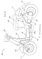
- FIG. 1 is a side view of a first embodiment of a fuel battery mounted motorcycle of the present invention.
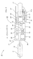
- FIG. 2 is a plan diagram showing the layout of a fuel battery system of the fuel battery mounted motorcycle according to the first embodiment of the present invention.
- FIG. 3 is a diagram illustrating the operation of the fuel battery system of the fuel battery mounted motorcycle according to the first embodiment of the present invention.
- FIG. 4 is a plan diagram showing the layout of a first modification of the fuel battery system of the fuel battery mounted motorcycle according to the first embodiment of the present invention.
- FIG. 5 is a plan diagram showing the layout of a second modification of the fuel battery system of the fuel battery mounted motorcycle according to the first embodiment of the present invention.
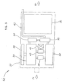
- FIG. 6 is a front diagram showing the layout of a third modification of the fuel battery system of the fuel battery mounted motorcycle according to the first embodiment of the present invention.
- FIG. 7 is a front diagram showing the layout of a fourth modification of the fuel battery system of the fuel battery mounted motorcycle according to the first embodiment of the present invention.
- FIG. 8 is a front diagram showing the layout of a fifth modification of the fuel battery system of the fuel battery mounted motorcycle according to the first embodiment of the present invention.
- FIG. 9 is a side view of a second embodiment of the fuel battery mounted motorcycle according to the present invention.
- FIG. 10 is a side view of a third embodiment of the fuel battery mounted motorcycle according to the present invention.
- FIG. 11 is a side view of a fourth embodiment of the fuel battery mounted motorcycle according to the present invention.
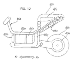
- FIG. 12 is a side view of a fifth embodiment of the fuel battery mounted motorcycle according to the present invention.
- FIG. 13 is a side view of a sixth embodiment of the fuel battery mounted motorcycle according to the present invention.
- FIG. 14 is a side view of a seventh embodiment of the fuel battery mounted motorcycle according to the present invention.
- FIGS. 15(a) and 15(b) are diagrams illustrating the power generation principle of a fuel battery.
- FIG. 16 is a block diagram showing one example of a fuel battery system.
- FIG. 1 is a side view of a first embodiment of a fuel battery mounted motorcycle according to the present invention.
- a fuel battery mounted motorcycle 10 hereinafter, referred to simply as "motorcycle 10"
- scooter-type motorcycle including a low level floor.
- the motorcycle 10 mainly includes a front fork 13 mounted to a head pipe 12 of a body frame 11; a front wheel 14 mounted to the front fork 13; a handlebar 15 connected to the front fork 13; a swing unit 16 mounted to an upper rear portion of the body frame 11; a rear wheel 17 mounted to a rear portion of the swing unit 16: a seat 18 disposed on an upper rear portion of the body frame 11; a fuel battery system 30 with its main portion disposed under the body frame 11; and a power unit 45 driven by the fuel battery system 30.
- reference numeral 19 designates a helmet box
- 21 is a rear suspension.
- the body frame 11 includes a down tube 22 extending rearwardly from the head pipe 12, and a center tube 23 extending rearwardly from the down tube 22.
- a pair of right and left rear pipes 24 (only one is shown in the figure) extend from a mid point of the center tube 23.
- a front stay 25 extends downwardly from a mid point of the down tube 22 and a rear stay 26 extends downwardly from the rear end of the center tube 23.
- a low level type floor 27 is provided in such a manner as to connect the lower ends of the front and rear stays 25 and 26 to each other.
- FIG. 2 is a plan diagram showing the layout of the fuel battery system of the fuel battery mounted motorcycle according to the first embodiment of the present invention.
- the fuel battery system 30 includes a fuel tank 31 for storing methanol; a reformer 32 for generating hydrogen from methanol supplied from the fuel tank 31 and water; a fuel battery 33 for making hydrogen generated by the reformer 32 electrochemically react with oxygen in air; a catalyzer 34 for receiving water from the fuel battery 33 and carbon dioxide from the reformer 32 via the fuel battery 33 and reducing the amount of carbon dioxide; a water tank 35 for receiving water from the catalyzer 34; and a plurality of secondary batteries 36 for storing an electric power generated by the fuel battery 33 and also storing an electric power generated by the power unit 45.
- character C designates the center plane of a vehicular body of the motorcycle 10.
- the fuel battery 33 includes a radiator 38 for cooling the fuel battery 33; a first pump 39 for supplying hydrogen from the reformer 32 to the fuel battery 33; and a second pump 42 for supplying oxygen in air to the fuel battery 33 via an air cleaner 41.
- the water tank 35 includes an exhaust pipe 43 for discharging water vapor.
- the power unit 45 includes a motor 46 driven by the secondary batteries 36 and the fuel battery 33; a belt-type automatic transmission 47 connected to the motor 46; and a control unit 48 for controlling these belt-type automatic transmission 47 and the motor 46.
- reference numeral 47a designates a case of the belt-type automatic transmission 47.
- the motorcycle 10 including the low level floor 27 is configured such that at least one of the fuel battery 33 and the reformer 32 is disposed in a lower portion of the floor 27.
- the center of gravity of the motorcycle 10 can be lowered and the floor 27 is effectively utilized for the purpose other than the original purpose of the floor 27.
- the motorcycle 10 is also configured such that the reformer 32 for generating hydrogen is disposed, together with the fuel battery 33, in a lower portion of the floor 27. As a result, the center of gravity of the motorcycle 10 can be further lowered and pipes used for connecting the reformer 32 to the fuel battery 33 can be shortened.
- the motorcycle 10 is further configured such that the secondary batteries 36 are disposed, together with the fuel battery 33, in a lower portion of the floor 27. As a result, the center of gravity of the motorcycle 10 can be lowered. That is to say, since the heavy secondary batteries 36 and fuel battery 33 are disposed in the lower portion of the floor 27, the center of gravity of the motorcycle 10 can be further lowered.
- the motorcycle 10 is further configured such that the reformer 32 for generating hydrogen is disposed, together with the fuel battery 33 and the secondary batteries 36, in a lower portion of the floor 27.
- the center of gravity of the motorcycle 10 can be further lowered and the floor 27 can be effectively utilized for the purpose other than the original purpose of the floor 27.
- the system using the reformer 32, fuel battery 33, and secondary batteries 36 can be centralized, and wires or pipes for electrically or fluidly connecting the reformer 32, fuel battery 33, and secondary batteries 36 to each other can be shortened.
- the motorcycle 10 including the fuel battery 33, secondary batteries 36, motor 46, and belt-type automatic transmission 47 is configured such that the belt-type automatic transmission 47 is disposed on one side with respect to the center plane C of the vehicular body and the secondary batteries 36 is disposed on the other side with respect to the center plane C of the vehicular body.
- the weights on the right and left sides of the motorcycle 10 can be kept in balance.
- FIG. 3 is a diagram illustrating the operation of the fuel battery system of the fuel battery mounted motorcycle of the present invention.
- methanol, oxygen, hydrogen, and water flow in respective directions shown by arrows (1) to (6).
- methanol is supplied from the fuel tank 31 to the reformer 32 as shown by the arrow (1) and water is supplied from the water tank 35 to the reformer 32 as shown by the arrow (2), and hydrogen produced by the reforming in the reformer 32 is supplied to the fuel battery 33 along the direction arrow (3) and oxygen in air is supplied to the fuel battery 33 via the air cleaner 41 as shown by the arrow (4) by the second pump 42, to generate an electric power in the fuel battery 33.
- Water vapor and carbon dioxide are discharged from the fuel battery 33 to the catalyzer 34 as shown by the arrow (5) to reduce the amount of carbon dioxide, and part of water vapor is discharged to atmospheric air from the exhaust pipe 43 as shown by the arrow (6) and the residue of water vapor is stored in the water tank 35 to be circulated to the reformer 32 as described.
- FIG. 4 is a plan diagram showing the layout of a first modification of the fuel battery system of the fuel battery mounted motorcycle according to the first embodiment of the present invention.
- a fuel battery system 51 for the sake of clarity, parts corresponding to those of the above-described fuel battery system 30 are designated by the same reference numerals. That is to say, reference numeral 27 designates a floor; 32 is a reformer; 33 is a fuel battery; 34 is a catalyzer; 35 is a water tank; 36 is a secondary battery; 38 is a radiator; 39 is a first pump; 41 is an air cleaner; 42 is a second pump; and 43 is an exhaust pipe.
- the fuel battery system 51 is configured such that the heavy secondary battery 36 is disposed on the front side of a lower portion of the floor 27.
- the secondary battery 36 is disposed on the front side of the lower portion of the floor 27 and the fuel battery 33 is disposed on the rear side of the lower portion of the floor 27, it is possible to easily perform the maintenance of the secondary battery 36, and to increase a load distributed on the front wheel 14 (see FIG. 1) of the motorcycle 10 and thereby keep the weight of the front wheel 14 in balance against the weight of the rear wheel 17.
- FIG. 5 is a plan diagram showing the layout of a second modification of the fuel battery system of the fuel battery mounted motorcycle according to the first embodiment of the present invention.
- reference numeral 27 designates a floor
- 32 is a reformer
- 33 is a fuel battery
- 34 is a catalyzer
- 35 is a water tank
- 36 is a secondary battery
- 38 is a radiator
- 39 is a first pump
- 41 is an air cleaner
- 42 is a second pump
- 43 is an exhaust pipe.
- the fuel battery system 52 is configured such that the heavy secondary battery 36 is disposed on the rear side of a lower portion of the floor 27. As a result, it is possible to improve the effect of cooling the reformer 32 and the fuel battery 33.
- FIG. 6 is a front diagram showing the layout of a third modification of the fuel battery system of the fuel battery mounted motorcycle according to the first embodiment of the present invention.
- a fuel battery system 53 for the sake of clarity, parts corresponding to those of the above-described fuel battery system 30 are designated by the same reference numerals. That is to say, reference numeral 27 designates a floor; 32 is a reformer; 33 is a fuel battery; and 36 is a secondary battery.
- the fuel battery system 53 is configured such that the fuel battery 33 and the reformer 32 are disposed in a lower portion of the floor 27 and the secondary battery 36 is disposed on these fuel battery 33 and the reformer 32.
- FIG. 7 is a front diagram showing the layout of a fourth modification of the fuel battery system of the fuel battery mounted motorcycle according to the first embodiment of the present invention.
- a fuel battery system 54 for the sake of clarity, parts corresponding to those of the above-described fuel battery system 30 are designated by the same reference numerals. That is to say, reference numeral 27 designates a floor; 32 is a reformer; 33 is a fuel battery; and 36 is a secondary battery.
- the fuel battery system 54 is configured such that the secondary battery 36 is disposed in a lower portion of the floor 27 and the fuel battery 33 and the reformer 32 are disposed on the secondary battery 36.
- FIG. 8 is a front diagram showing the layout of a fifth modification of the fuel battery system of the fuel battery mounted motorcycle according to the first embodiment of the present invention.
- a fuel battery system 55 for the sake of clarity, parts corresponding to those of the above-described fuel battery system 30 are designated by the same reference numerals. That is to say, reference numeral 27 designates a floor; 32 is a reformer; 33 is a fuel battery; and 36 is a secondary battery.
- the fuel battery system 55 is configured such that the fuel battery 33 is disposed in a lower portion of the floor 27, and the secondary battery 36 and the reformer 32 are disposed on the fuel battery 33 in such a manner as to be located on the front and rear sides, respectively. As a result, it is possible to easily perform the maintenance of the secondary battery 36 and the reformer 32.
- FIG. 9 is a side view of a second embodiment of the fuel battery mounted motorcycle according to the present invention.
- reference numeral 61 designates a body frame
- 62 is a front frame made from aluminum by die-casting, which constitutes part of the body frame 61
- 63 is a rear frame made from aluminum by die-casting, which constitutes part of the body frame 61
- 64 is a front suspension
- 65 is a handlebar
- 66 is a swing unit
- 67 is a rear suspension
- 68 is a seat
- 69 is a helmet box
- 71 is a front wheel
- 72 is a rear wheel
- 73 is a drive unit composed of a transmission and a motor.
- a fuel battery mounted motorcycle 60 (hereinafter, referred to as "motorcycle 60") is configured such that a power generation unit 76 mainly including a fuel battery, a reformer, and a secondary battery is mounted in a lower portion of a floor 62a of the die-cast front frame 62, and a fuel tank 77 for storing methanol is mounted to the die-cast rear frame 63.
- a power generation unit 76 mainly including a fuel battery, a reformer, and a secondary battery is mounted in a lower portion of a floor 62a of the die-cast front frame 62
- a fuel tank 77 for storing methanol is mounted to the die-cast rear frame 63.
- the body frame 62 is divided into the die-cast front frame 62 and the die-cast rear frame 63, and the respective components are mounted to the frames 62 and 63. As a result, it is possible to easily assemble the motorcycle 60 and hence to reduce the assembling cost.
- FIG. 10 is a side view of a third embodiment of the fuel battery mounted motorcycle according to the present invention.
- a fuel battery mounted motorcycle 83 (hereinafter, referred to as "motorcycle 83") is configured such that a plurality of secondary batteries 83c are disposed in a lower portion of a floor 83b of a body frame 83a, and a fuel battery 83e, a reformer 83f for generating hydrogen, and a fuel tank 83g for storing methanol are disposed on the secondary batteries 83c in this order from the front side.
- reference numeral 83h designates a radiator provided on the fuel battery 83e; 83i is a seat; and 83j is a helmet box.
- FIG. 11 is a side view of a fourth embodiment of the fuel battery mounted motorcycle according to the present invention.
- a fuel battery mounted motorcycle 84 (hereinafter, referred to as "motorcycle 84") is configured such that a fuel battery 84e, a reformer 84f, and a fuel tank 84g are disposed in a lower portion of the floor 84b of a body frame 84a, and a plurality of secondary batteries 84c are disposed on a rear portion of the body frame 84a.
- reference numeral 84h designates a radiator provided on the fuel battery 84e; 84i is a seat; and 84j is a helmet box.
- FIG. 12 is a side view of a fifth embodiment of the fuel battery mounted motorcycle according to the present invention.
- a fuel battery mounted motorcycle 85 (hereinafter, referred to as "motorcycle 85") is configured such that a fuel battery 85e, a reformer 85f, and an L-shaped fuel tank 85g are disposed in a lower portion of a floor 85b of a body frame 85a, and a plurality of secondary batteries 85c are disposed on a rear portion of the body frame 85a.
- reference numeral 85h designates a radiator provided on the fuel battery 85e; 85i is a seat; and 85j is a helmet box.
- the motorcycle 85 is intended to directly drive a rear wheel 85k by a motor 85n with a transmission.
- FIG. 13 is a side view of a sixth embodiment of the fuel battery mounted motorcycle according to the present invention.
- a fuel battery mounted motorcycle 86 (hereinafter, referred to as "motorcycle 86") is configured such that a fuel battery 86e is disposed under a front portion of a seat 86i, and secondary batteries 86c and 86d, a fuel tank 86g for storing methanol, and a reformer 86f for generating hydrogen are disposed in a lower portion of a floor 86b of a body frame 86a.
- This layout is suitable for a large-sized scooter type motorcycle.
- reference numeral 86j designates a helmet box.
- the fuel battery 86e is disposed under the front portion of the seat 86i, it is possible to enlarge an inner space of the floor 86b.
- FIG. 14 is a side view of a seventh embodiment of the fuel battery mounted motorcycle according to the present invention.
- reference numeral 87a designates a body frame
- 87b is a floor
- 87c and 87d are secondary batteries
- 87g is a fuel tank
- 87f is a reformer
- 87j is a helmet box.
- a fuel battery mounted motorcycle 87 (hereinafter, referred to as "motorcycle 87”) is configured such that the fuel battery 87e is disposed under a rear portion of the seat 87i.
- the fuel battery 87e is disposed under the rear portion of the seat 87i, it is possible to enlarge an inner space of the floor 87b.
- the fuel tank 31 is provided on the body frame 11 as shown in FIG. 1; however, the present invention is not limited thereto.
- the fuel tank 31 may be provided, together with the fuel battery 33, reformer 32, and secondary batteries 36 (see FIG. 2), in the lower portion of the floor 27.
- the secondary battery 36 is disposed on the front side and the reformer 32 is disposed on the rear side; however, the present invention is not limited thereto but may be configured such that the secondary battery 36 be disposed on the rear side and the reformer 32 is disposed on the front side.
- the secondary battery is located on the front side of the lower portion of the floor and the fuel battery is disposed on the rear side of the lower portion of the floor, it is possible to increase a load distributed on a front wheel and thereby keep the weight of the front wheel in balance against the weight of a rear wheel, and to improve the maintenance workability of the secondary battery.
- the secondary battery and the fuel battery are stacked in the vertical direction in the lower portion of the floor.
- the reformer for generating hydrogen is disposed, together with the fuel battery and secondary battery, in the lower portion of the floor, it is possible to lower the center of gravity of the motorcycle, to centralize the system including the reformer, fuel battery, and secondary battery, and to shorten wires or pipes for electrically or fluidly connecting them to each other.
- the belt type automatic transmission is disposed on one side with respect to a center plane of a vehicular body of the motorcycle, and the secondary battery is disposed on the other side with respect to the center plane of the vehicular body, it is possible to keep the weights on the right and left sides of the motorcycle in balance.
- the center of gravity of the motorcycle can be lowered and the floor can be effectively utilized for the purpose other than the original purpose of the floor.
Landscapes
- Engineering & Computer Science (AREA)
- Mechanical Engineering (AREA)
- Transportation (AREA)
- Sustainable Energy (AREA)
- Power Engineering (AREA)
- Life Sciences & Earth Sciences (AREA)
- Sustainable Development (AREA)
- Chemical & Material Sciences (AREA)
- Combustion & Propulsion (AREA)
- Fuel Cell (AREA)
- Arrangement Or Mounting Of Propulsion Units For Vehicles (AREA)
- Electric Propulsion And Braking For Vehicles (AREA)
- Automatic Cycles, And Cycles In General (AREA)
Abstract
Description
- The present invention relates to a fuel battery mounted motorcycle.
- Fuel battery mounted motorcycles are known, for example, from Japanese Patent Laid-open No. Hei 3-109126 entitled "Fuel Battery Mounted Motorcycle".
- As shown in FIG. 1 of the above document, the above technique discloses an electric motorcar 1 using a
fuel battery 13 as an energy source, wherein thefuel battery 13 is disposed in a lower central portion of a vehicular body 2 (note: reference numerals are cited from the document) . - In the case of using the
fuel battery 13 as an energy source, as will be described later, the motorcycle 1 must be provided with, in addition to thefuel battery 13, a fuel tank for storing methanol, a reformer for generating hydrogen, a secondary battery for storing an electric power generated by thefuel battery 13, and the like. Further, in the case of mounting a fuel battery like thefuel battery 13 on a motorcycle, the layout of the fuel battery, reformer, secondary battery, and the like becomes important. The principle of power generation by a fuel battery and one example of a fuel battery system will be hereinafter described. - FIGS. 15(a) and 15(b) are diagrams illustrating the principle of power generation by a fuel battery, wherein FIG. 15(a) shows the principle of electrolysis of water, and FIG. 15(b) shows the principle of power generation by the fuel battery.
- Referring to FIG. 15(a), the electrolytic process of water (H2O) is performed by filling a
water tank 101 with water (H2O) in which an electrolyte such as sulfuric acid (H2SO4) has been dissolved; settingelectrodes water tank 101; covering theelectrodes containers DC power source 106, between theelectrodes electrode 102 side taken as the plus side and hydrogen gas (H2) is generated on theelectrode 103 side taken as the minus side. In the figure, an arrow (e-) designates the flow of electrons and an arrow (H+) designates the flow of hydrogen ions. - Referring to FIG. 15(b), the power generation process is performed in accordance with steps reversed to those shown in FIG. 15(a), that is, by filling the
container 104 with oxygen gas (O2) and thecontainer 105 with hydrogen gas (H2); connecting aload 107 between theelectrodes load 107, and the oxygen gas (O2) is bonded to the hydrogen gas (H2) to produce water (H2O). - In this way, as shown in FIG. 5(b), the process of power generation of a fuel battery is reversed to the process of electrolysis of water shown in FIG. 5(a). The fuel battery system will be described with reference to FIG. 16.
- FIG. 16 is a block diagram showing one example of the fuel battery system. A
fuel battery system 110 includes afuel tank 111 for storing methanol; areformer 112 for generating hydrogen from methanol and water; afuel battery 113 for making hydrogen generated by thereformer 112 electrochemically react with oxygen in air; afirst pump 115 for supplying outside air to thefuel battery 113 via anair cleaner 114; asecond pump 116 for supplying hydrogen from thereformer 112 to thefuel battery 113; acatalyzer 117 for receiving water vapor from thefuel battery 113 and carbon dioxide gas from thereformer 112 via thefuel battery 113 and for reducing the amount of carbon dioxide gas; awater tank 118 for receiving water from thecatalyzer 117; asecondary battery 119 for storing an electric power generated by thefuel battery 113; and amotor 122 connected to thesecondary battery 119 via acontrol unit 121. In addition, thesecondary battery 119 also functions to store an electric power generated by themotor 122. - In the figure, a hollow arrow (CH3OH) designates the flow of methanol; a hollow arrow (H2) is the flow of hydrogen gas; a hollow arrow (O2) is the flow of oxygen gas; a hollow arrow (H2O + CO2) is the flow of water vapor and carbon dioxide gas; and a hollow arrow (H2O) is the flow of water.
- As described above, in the case of using the
fuel battery 113 as an energy source of a motorcycle (not shown), it is required to provide, in addition to thefuel battery 113, thefuel tank 111 for storing methanol, thereformer 112 for generating hydrogen, thesecondary battery 119 for storing an electric power generated by thefuel battery 113, and the like; and in the case of actually mounting thesefuel battery 113,fuel tank 111,reformer 112, and the like on a motorcycle, it is required to examine the layout of thefuel battery system 110 including thefuel battery 113,fuel tank 111,reformer 112, and the like from the viewpoint of various factors such as the weight balance, maintenance, and design. - An object of the present invention is to provide a technique of mounting a fuel battery on a motorcycle, which is capable of optimally arranging the fuel battery, a reformer, a secondary battery, and the like.
- To achieve the above object, according to an invention described in claim 1, there is provided a fuel battery mounted motorcycle including a low level floor, characterized in that at least one of a fuel battery and a reformer for generating hydrogen is disposed in a lower portion of the floor.
- With this configuration, since at least one of the fuel battery and the reformer for generating hydrogen is disposed in a lower portion of the floor, it is possible to lower the center of gravity of the motorcycle.
- According to an invention described in claim 2, the reformer for generating hydrogen is disposed, together with the fuel battery, in a lower portion of the floor.
- With this configuration, since the reformer for generating hydrogen is disposed, together with the fuel battery, in the lower portion of the floor, it is possible to further lower the center of gravity of the motorcycle, and also to shorten pipes for connecting the fuel battery to the reformer.
- According to an invention described in
claim 3, a secondary battery is disposed, together with the fuel battery, in a lower portion of the floor. - With this configuration, since the secondary battery is disposed, together with the fuel battery, in the lower portion of the floor, it is possible to lower the center of gravity of the motorcycle.
- According to an invention described in
claim 4, the secondary battery is located on the front side of the lower portion of the floor and the fuel battery is disposed on the rear side of the lower portion of the floor. - With this configuration, since the secondary battery is located on the front side of the lower portion of the floor and the fuel battery is disposed on the rear side of the lower portion of the floor, it is possible to increase a load distributed on a front wheel and thereby keep the weight of the front wheel in balance against the weight of a rear wheel, and to improve the maintenance workability of the secondary battery.
- According to an invention described in
claim 5, the secondary battery and the fuel battery are stacked in the vertical direction in the lower portion of the floor. - With this configuration, it is possible to easily change the capacity of the secondary battery by disposing the secondary battery on the fuel battery, and to lower the center of gravity of the motorcycle by disposing the secondary battery under the fuel battery.
- According to an invention described in
claim 6, the reformer is disposed, together with the fuel battery and the secondary battery, in the lower portion of the floor. - With this configuration, since the reformer for generating hydrogen is disposed, together with the fuel battery and secondary battery, in the lower portion of the floor, it is possible to lower the center of gravity of the motorcycle, to centralize the system including the reformer, fuel battery, and secondary battery, and to shorten wires or pipes for electrically or fluidly connecting them to each other.
- According to an invention described in claim 7, there is provided a fuel battery mounted motorcycle including a fuel battery, a secondary battery, a motor, and a belt-type automatic transmission, characterized in that the belt-type automatic transmission is disposed on one side with respect to a center plane of a vehicular body of the motorcycle, and the secondary battery is disposed on the other side with respect to the center plane of the vehicular body.
- With this configuration, since the belt type automatic transmission is disposed on one side with respect to a center plane of a vehicular body of the motorcycle, and the secondary battery is disposed on the other side with respect to the center plane of the vehicular body, it is possible to keep the weights on the right and left sides of the motorcycle in balance.
- Hereinafter, embodiments of the present invention will be described with reference to the accompanying drawings.
- FIG. 1 is a side view of a first embodiment of a fuel battery mounted motorcycle of the present invention.
- FIG. 2 is a plan diagram showing the layout of a fuel battery system of the fuel battery mounted motorcycle according to the first embodiment of the present invention.
- FIG. 3 is a diagram illustrating the operation of the fuel battery system of the fuel battery mounted motorcycle according to the first embodiment of the present invention.
- FIG. 4 is a plan diagram showing the layout of a first modification of the fuel battery system of the fuel battery mounted motorcycle according to the first embodiment of the present invention.
- FIG. 5 is a plan diagram showing the layout of a second modification of the fuel battery system of the fuel battery mounted motorcycle according to the first embodiment of the present invention.
- FIG. 6 is a front diagram showing the layout of a third modification of the fuel battery system of the fuel battery mounted motorcycle according to the first embodiment of the present invention.
- FIG. 7 is a front diagram showing the layout of a fourth modification of the fuel battery system of the fuel battery mounted motorcycle according to the first embodiment of the present invention.
- FIG. 8 is a front diagram showing the layout of a fifth modification of the fuel battery system of the fuel battery mounted motorcycle according to the first embodiment of the present invention.
- FIG. 9 is a side view of a second embodiment of the fuel battery mounted motorcycle according to the present invention.
- FIG. 10 is a side view of a third embodiment of the fuel battery mounted motorcycle according to the present invention.
- FIG. 11 is a side view of a fourth embodiment of the fuel battery mounted motorcycle according to the present invention.
- FIG. 12 is a side view of a fifth embodiment of the fuel battery mounted motorcycle according to the present invention.
- FIG. 13 is a side view of a sixth embodiment of the fuel battery mounted motorcycle according to the present invention.
- FIG. 14 is a side view of a seventh embodiment of the fuel battery mounted motorcycle according to the present invention.
- FIGS. 15(a) and 15(b) are diagrams illustrating the power generation principle of a fuel battery.
- FIG. 16 is a block diagram showing one example of a fuel battery system.
- In the drawings, the "front", "rear", "left", "right", "upper", "lower" sides are based on the line of view of the driver riding on a motorcycle to which the present invention is applied, and characters "Fr", "Rr", "L", and "R" designate the front, rear, left, and right sides, respectively. Additionally, the drawings should be viewed in the direction of characters.
- FIG. 1 is a side view of a first embodiment of a fuel battery mounted motorcycle according to the present invention. Referring to this figure, there is shown a fuel battery mounted motorcycle 10 (hereinafter, referred to simply as "
motorcycle 10"), which is configured, according to this embodiment, as a scooter-type motorcycle including a low level floor. Themotorcycle 10 mainly includes afront fork 13 mounted to ahead pipe 12 of abody frame 11; afront wheel 14 mounted to thefront fork 13; ahandlebar 15 connected to thefront fork 13; aswing unit 16 mounted to an upper rear portion of thebody frame 11; arear wheel 17 mounted to a rear portion of the swing unit 16: aseat 18 disposed on an upper rear portion of thebody frame 11; afuel battery system 30 with its main portion disposed under thebody frame 11; and apower unit 45 driven by thefuel battery system 30. In the figure,reference numeral 19 designates a helmet box, and 21 is a rear suspension. - The
body frame 11 includes adown tube 22 extending rearwardly from thehead pipe 12, and acenter tube 23 extending rearwardly from thedown tube 22. A pair of right and left rear pipes 24 (only one is shown in the figure) extend from a mid point of thecenter tube 23. Afront stay 25 extends downwardly from a mid point of thedown tube 22 and arear stay 26 extends downwardly from the rear end of thecenter tube 23. A lowlevel type floor 27 is provided in such a manner as to connect the lower ends of the front andrear stays - FIG. 2 is a plan diagram showing the layout of the fuel battery system of the fuel battery mounted motorcycle according to the first embodiment of the present invention.
- The
fuel battery system 30 includes afuel tank 31 for storing methanol; areformer 32 for generating hydrogen from methanol supplied from thefuel tank 31 and water; afuel battery 33 for making hydrogen generated by thereformer 32 electrochemically react with oxygen in air; acatalyzer 34 for receiving water from thefuel battery 33 and carbon dioxide from thereformer 32 via thefuel battery 33 and reducing the amount of carbon dioxide; awater tank 35 for receiving water from thecatalyzer 34; and a plurality ofsecondary batteries 36 for storing an electric power generated by thefuel battery 33 and also storing an electric power generated by thepower unit 45. In the figure, character C designates the center plane of a vehicular body of themotorcycle 10. - The
fuel battery 33 includes aradiator 38 for cooling thefuel battery 33; afirst pump 39 for supplying hydrogen from thereformer 32 to thefuel battery 33; and asecond pump 42 for supplying oxygen in air to thefuel battery 33 via anair cleaner 41. Thewater tank 35 includes anexhaust pipe 43 for discharging water vapor. - The
power unit 45 includes amotor 46 driven by thesecondary batteries 36 and thefuel battery 33; a belt-typeautomatic transmission 47 connected to themotor 46; and acontrol unit 48 for controlling these belt-typeautomatic transmission 47 and themotor 46. In the figure,reference numeral 47a designates a case of the belt-typeautomatic transmission 47. - As shown in FIG. 2, the
motorcycle 10 including thelow level floor 27 is configured such that at least one of thefuel battery 33 and thereformer 32 is disposed in a lower portion of thefloor 27. As a result, the center of gravity of themotorcycle 10 can be lowered and thefloor 27 is effectively utilized for the purpose other than the original purpose of thefloor 27. - The
motorcycle 10 is also configured such that thereformer 32 for generating hydrogen is disposed, together with thefuel battery 33, in a lower portion of thefloor 27. As a result, the center of gravity of themotorcycle 10 can be further lowered and pipes used for connecting thereformer 32 to thefuel battery 33 can be shortened. - The
motorcycle 10 is further configured such that thesecondary batteries 36 are disposed, together with thefuel battery 33, in a lower portion of thefloor 27. As a result, the center of gravity of themotorcycle 10 can be lowered. That is to say, since the heavysecondary batteries 36 andfuel battery 33 are disposed in the lower portion of thefloor 27, the center of gravity of themotorcycle 10 can be further lowered. - The
motorcycle 10 is further configured such that thereformer 32 for generating hydrogen is disposed, together with thefuel battery 33 and thesecondary batteries 36, in a lower portion of thefloor 27. As a result, the center of gravity of themotorcycle 10 can be further lowered and thefloor 27 can be effectively utilized for the purpose other than the original purpose of thefloor 27. Further, the system using thereformer 32,fuel battery 33, andsecondary batteries 36 can be centralized, and wires or pipes for electrically or fluidly connecting thereformer 32,fuel battery 33, andsecondary batteries 36 to each other can be shortened. - As shown in FIG. 2, the
motorcycle 10 including thefuel battery 33,secondary batteries 36,motor 46, and belt-typeautomatic transmission 47 according to this embodiment is configured such that the belt-typeautomatic transmission 47 is disposed on one side with respect to the center plane C of the vehicular body and thesecondary batteries 36 is disposed on the other side with respect to the center plane C of the vehicular body. As a result, the weights on the right and left sides of themotorcycle 10 can be kept in balance. - The operation of the above-described
fuel battery system 30 will be described below. - FIG. 3 is a diagram illustrating the operation of the fuel battery system of the fuel battery mounted motorcycle of the present invention. In this figure, methanol, oxygen, hydrogen, and water flow in respective directions shown by arrows (1) to (6).
- In the
fuel battery system 30, methanol is supplied from thefuel tank 31 to thereformer 32 as shown by the arrow (1) and water is supplied from thewater tank 35 to thereformer 32 as shown by the arrow (2), and hydrogen produced by the reforming in thereformer 32 is supplied to thefuel battery 33 along the direction arrow (3) and oxygen in air is supplied to thefuel battery 33 via theair cleaner 41 as shown by the arrow (4) by thesecond pump 42, to generate an electric power in thefuel battery 33. Water vapor and carbon dioxide are discharged from thefuel battery 33 to thecatalyzer 34 as shown by the arrow (5) to reduce the amount of carbon dioxide, and part of water vapor is discharged to atmospheric air from theexhaust pipe 43 as shown by the arrow (6) and the residue of water vapor is stored in thewater tank 35 to be circulated to thereformer 32 as described. - FIG. 4 is a plan diagram showing the layout of a first modification of the fuel battery system of the fuel battery mounted motorcycle according to the first embodiment of the present invention. In this figure showing a
fuel battery system 51, for the sake of clarity, parts corresponding to those of the above-describedfuel battery system 30 are designated by the same reference numerals. That is to say,reference numeral 27 designates a floor; 32 is a reformer; 33 is a fuel battery; 34 is a catalyzer; 35 is a water tank; 36 is a secondary battery; 38 is a radiator; 39 is a first pump; 41 is an air cleaner; 42 is a second pump; and 43 is an exhaust pipe. As shown in this figure, thefuel battery system 51 is configured such that the heavysecondary battery 36 is disposed on the front side of a lower portion of thefloor 27. - In the motorcycle 10 (see FIG. 1) having the above-described
fuel system 51, since thesecondary battery 36 is disposed on the front side of the lower portion of thefloor 27 and thefuel battery 33 is disposed on the rear side of the lower portion of thefloor 27, it is possible to easily perform the maintenance of thesecondary battery 36, and to increase a load distributed on the front wheel 14 (see FIG. 1) of themotorcycle 10 and thereby keep the weight of thefront wheel 14 in balance against the weight of therear wheel 17. - FIG. 5 is a plan diagram showing the layout of a second modification of the fuel battery system of the fuel battery mounted motorcycle according to the first embodiment of the present invention. In this figure showing a
fuel battery system 52, for the sake of clarity, parts corresponding to those of the above-describedfuel battery system 30 are designated by the same reference numerals. That is to say,reference numeral 27 designates a floor; 32 is a reformer; 33 is a fuel battery; 34 is a catalyzer; 35 is a water tank; 36 is a secondary battery; 38 is a radiator; 39 is a first pump; 41 is an air cleaner; 42 is a second pump; and 43 is an exhaust pipe. As shown in this figure, thefuel battery system 52 is configured such that the heavysecondary battery 36 is disposed on the rear side of a lower portion of thefloor 27. As a result, it is possible to improve the effect of cooling thereformer 32 and thefuel battery 33. - FIG. 6 is a front diagram showing the layout of a third modification of the fuel battery system of the fuel battery mounted motorcycle according to the first embodiment of the present invention. In this figure showing a
fuel battery system 53, for the sake of clarity, parts corresponding to those of the above-describedfuel battery system 30 are designated by the same reference numerals. That is to say,reference numeral 27 designates a floor; 32 is a reformer; 33 is a fuel battery; and 36 is a secondary battery. As shown in this figure, thefuel battery system 53 is configured such that thefuel battery 33 and thereformer 32 are disposed in a lower portion of thefloor 27 and thesecondary battery 36 is disposed on thesefuel battery 33 and thereformer 32. - In the motorcycle 10 (see FIG. 1) including the
above fuel system 53, since thesecondary battery 36 and thefuel battery 33 are stacked to each other in the vertical direction, it is possible to easily change the capacity of thesecondary battery 36. - FIG. 7 is a front diagram showing the layout of a fourth modification of the fuel battery system of the fuel battery mounted motorcycle according to the first embodiment of the present invention. In this figure showing a
fuel battery system 54, for the sake of clarity, parts corresponding to those of the above-describedfuel battery system 30 are designated by the same reference numerals. That is to say,reference numeral 27 designates a floor; 32 is a reformer; 33 is a fuel battery; and 36 is a secondary battery. As shown in this figure, thefuel battery system 54 is configured such that thesecondary battery 36 is disposed in a lower portion of thefloor 27 and thefuel battery 33 and thereformer 32 are disposed on thesecondary battery 36. - In the motorcycle 10 (see FIG. 1) including the
fuel system 54, since thesecondary battery 36 and thefuel battery 33 are stacked to each other in the vertical direction, it is possible to lower the center of gravity of themotorcycle 10 by disposing thesecondary battery 36 under thefuel battery 33. - FIG. 8 is a front diagram showing the layout of a fifth modification of the fuel battery system of the fuel battery mounted motorcycle according to the first embodiment of the present invention. In this figure showing a
fuel battery system 55, for the sake of clarity, parts corresponding to those of the above-describedfuel battery system 30 are designated by the same reference numerals. That is to say,reference numeral 27 designates a floor; 32 is a reformer; 33 is a fuel battery; and 36 is a secondary battery. As shown in this figure, thefuel battery system 55 is configured such that thefuel battery 33 is disposed in a lower portion of thefloor 27, and thesecondary battery 36 and thereformer 32 are disposed on thefuel battery 33 in such a manner as to be located on the front and rear sides, respectively. As a result, it is possible to easily perform the maintenance of thesecondary battery 36 and thereformer 32. - FIG. 9 is a side view of a second embodiment of the fuel battery mounted motorcycle according to the present invention. In this figure,
reference numeral 61 designates a body frame; 62 is a front frame made from aluminum by die-casting, which constitutes part of thebody frame 61; 63 is a rear frame made from aluminum by die-casting, which constitutes part of thebody frame 61; 64 is a front suspension; 65 is a handlebar; 66 is a swing unit; 67 is a rear suspension; 68 is a seat; 69 is a helmet box; 71 is a front wheel; 72 is a rear wheel; and 73 is a drive unit composed of a transmission and a motor. As shown in this figure, a fuel battery mounted motorcycle 60 (hereinafter, referred to as "motorcycle 60") is configured such that apower generation unit 76 mainly including a fuel battery, a reformer, and a secondary battery is mounted in a lower portion of afloor 62a of the die-cast front frame 62, and afuel tank 77 for storing methanol is mounted to the die-castrear frame 63. - In the
motorcycle 60, thebody frame 62 is divided into the die-cast front frame 62 and the die-castrear frame 63, and the respective components are mounted to theframes motorcycle 60 and hence to reduce the assembling cost. - FIG. 10 is a side view of a third embodiment of the fuel battery mounted motorcycle according to the present invention. A fuel battery mounted motorcycle 83 (hereinafter, referred to as "
motorcycle 83") is configured such that a plurality of secondary batteries 83c are disposed in a lower portion of afloor 83b of abody frame 83a, and afuel battery 83e, areformer 83f for generating hydrogen, and afuel tank 83g for storing methanol are disposed on the secondary batteries 83c in this order from the front side. In this figure,reference numeral 83h designates a radiator provided on thefuel battery 83e; 83i is a seat; and 83j is a helmet box. With this configuration, since the secondary batteries 83c and thefuel battery 83e are disposed in the lower portion of thefloor 83b of thebody frame 83a, it is possible to lower the center of gravity of themotorcycle 83. - Fig. 11 is a side view of a fourth embodiment of the fuel battery mounted motorcycle according to the present invention. A fuel battery mounted motorcycle 84 (hereinafter, referred to as "
motorcycle 84") is configured such that afuel battery 84e, areformer 84f, and afuel tank 84g are disposed in a lower portion of thefloor 84b of abody frame 84a, and a plurality of secondary batteries 84c are disposed on a rear portion of thebody frame 84a. In this figure,reference numeral 84h designates a radiator provided on thefuel battery 84e; 84i is a seat; and 84j is a helmet box. With this configuration, since the secondary batteries 84c are disposed on the rear portion of thebody frame 84a, it is possible to enlarge an inner space of thefloor 84b of themotorcycle 84. - FIG. 12 is a side view of a fifth embodiment of the fuel battery mounted motorcycle according to the present invention. A fuel battery mounted motorcycle 85 (hereinafter, referred to as "
motorcycle 85") is configured such that afuel battery 85e, areformer 85f, and an L-shapedfuel tank 85g are disposed in a lower portion of a floor 85b of abody frame 85a, and a plurality ofsecondary batteries 85c are disposed on a rear portion of thebody frame 85a. In this figure,reference numeral 85h designates a radiator provided on thefuel battery 85e; 85i is a seat; and 85j is a helmet box. In addition, themotorcycle 85 is intended to directly drive arear wheel 85k by amotor 85n with a transmission. - With this configuration, since the L-shaped
fuel tank 85g is disposed in the lower portion of the floor 85b of thebody frame 85a, it is possible to easily supply fuel to themotorcycle 85. - FIG. 13 is a side view of a sixth embodiment of the fuel battery mounted motorcycle according to the present invention. A fuel battery mounted motorcycle 86 (hereinafter, referred to as "
motorcycle 86") is configured such that afuel battery 86e is disposed under a front portion of a seat 86i, andsecondary batteries fuel tank 86g for storing methanol, and areformer 86f for generating hydrogen are disposed in a lower portion of afloor 86b of abody frame 86a. This layout is suitable for a large-sized scooter type motorcycle. In the figure, reference numeral 86j designates a helmet box. - According to the
motorcycle 86, since thefuel battery 86e is disposed under the front portion of the seat 86i, it is possible to enlarge an inner space of thefloor 86b. - FIG. 14 is a side view of a seventh embodiment of the fuel battery mounted motorcycle according to the present invention. In this figure,
reference numeral 87a designates a body frame; 87b is a floor; 87c and 87d are secondary batteries, 87g is a fuel tank; 87f is a reformer, and 87j is a helmet box. A fuel battery mounted motorcycle 87 (hereinafter, referred to as "motorcycle 87") is configured such that thefuel battery 87e is disposed under a rear portion of the seat 87i. - According to the
motorcycle 87, since thefuel battery 87e is disposed under the rear portion of the seat 87i, it is possible to enlarge an inner space of thefloor 87b. - According to the first embodiment, the
fuel tank 31 is provided on thebody frame 11 as shown in FIG. 1; however, the present invention is not limited thereto. For example, thefuel tank 31 may be provided, together with thefuel battery 33,reformer 32, and secondary batteries 36 (see FIG. 2), in the lower portion of thefloor 27. - Further, according to the first embodiment, the
secondary battery 36 is disposed on the front side and thereformer 32 is disposed on the rear side; however, the present invention is not limited thereto but may be configured such that thesecondary battery 36 be disposed on the rear side and thereformer 32 is disposed on the front side. - The present invention having the above-described configuration exhibits the following effects:
- In the motorcycle including the low level floor according to the invention described in claim 1, since at least one of a fuel battery and a reformer for generating hydrogen is disposed in a lower portion of the floor, it is possible to lower the center of gravity of the motorcycle, and hence to make effective use of the floor while lowering the center of gravity of the motorcycle.
- In the motorcycle according to the invention described in claim 2, since the reformer for generating hydrogen is disposed, together with the fuel battery, in the lower portion of the floor, it is possible to further lower the center of gravity of the motorcycle, and also to shorten pipes for connecting the fuel battery to the reformer.
- In the motorcycle according to the invention described in
claim 3, since the secondary battery is disposed, together with the fuel battery, in the lower portion of the floor, it is possible to lower the center of gravity of the motorcycle. That is to say, since the heavy secondary battery and fuel battery are disposed in the lower portion of the floor, it is possible to further lower the center of gravity of the motorcycle. - In the motorcycle according to the invention described in
claim 4, since the secondary battery is located on the front side of the lower portion of the floor and the fuel battery is disposed on the rear side of the lower portion of the floor, it is possible to increase a load distributed on a front wheel and thereby keep the weight of the front wheel in balance against the weight of a rear wheel, and to improve the maintenance workability of the secondary battery. - In the motorcycle according to the invention described in
claim 5, the secondary battery and the fuel battery are stacked in the vertical direction in the lower portion of the floor. - With this configuration, it is possible to easily change the capacity of the secondary battery by disposing the secondary battery on the fuel battery, and to lower the center of gravity of the motorcycle by disposing the secondary battery under the fuel battery.
- According to the motorcycle according to the invention described in
claim 6, since the reformer for generating hydrogen is disposed, together with the fuel battery and secondary battery, in the lower portion of the floor, it is possible to lower the center of gravity of the motorcycle, to centralize the system including the reformer, fuel battery, and secondary battery, and to shorten wires or pipes for electrically or fluidly connecting them to each other. - In the motorcycle including the fuel battery, secondary battery, motor, and belt-type automatic transmission according to the invention described in claim 7, since the belt type automatic transmission is disposed on one side with respect to a center plane of a vehicular body of the motorcycle, and the secondary battery is disposed on the other side with respect to the center plane of the vehicular body, it is possible to keep the weights on the right and left sides of the motorcycle in balance.
- In summary it is an object to provide a fuel battery mounted motorcycle intended to lower the center of gravity of the motorcycle by disposing a
reformer 32 for generating hydrogen, together with afuel battery 33 and asecondary battery 36, in a lower portion of afloor 27. - To achieve this, the center of gravity of the motorcycle can be lowered and the floor can be effectively utilized for the purpose other than the original purpose of the floor.
Claims (7)
- A fuel battery mounted motorcycle including a low level floor (27), characterized in that
at least one of a fuel battery (33) and a reformer (32) for generating hydrogen is disposed in a lower portion of said floor (27). - A fuel battery mounted motorcycle according to claim 1, wherein said reformer (32) for generating hydrogen is disposed, together with said fuel battery (33), in a lower portion of said floor (27).
- A fuel battery mounted motorcycle according to claim 1, wherein a secondary battery (36) is disposed, together with said fuel battery (33), in a lower portion of said floor (27).
- A fuel battery mounted motorcycle according to claim 3, wherein said secondary battery (36) is located on the front side of said lower portion of said floor (27) and said fuel battery (33) is disposed on the rear side of said lower portion of said floor (27).
- A fuel battery mounted motorcycle according to claim 3, wherein said secondary battery (36) and said fuel battery (33) are stacked in the vertical direction in said lower portion of said floor (27).
- A fuel battery mounted motorcycle according to claim 3, wherein said reformer (32) is disposed, together with said fuel battery (33) and said secondary battery (36), in said lower portion of said floor (27).
- A fuel battery mounted motorcycle including a fuel battery (33), a secondary battery (36) a motor (46) and a belt-type automatic transmission (47), characterized in that
said belt-type automatic transmission (47) is disposed on one side with respect to a center plane (C) of a vehicular body of said motorcycle (10), and said secondary battery (36) is disposed on the other side with respect to said center plane (C) of the vehicular body.
Applications Claiming Priority (2)
| Application Number | Priority Date | Filing Date | Title |
|---|---|---|---|
| JP2000178621 | 2000-06-14 | ||
| JP2000178621A JP2001354179A (en) | 2000-06-14 | 2000-06-14 | Motorcycle with fuel cell |
Publications (2)
| Publication Number | Publication Date |
|---|---|
| EP1164049A1 true EP1164049A1 (en) | 2001-12-19 |
| EP1164049B1 EP1164049B1 (en) | 2005-08-17 |
Family
ID=18680025
Family Applications (1)
| Application Number | Title | Priority Date | Filing Date |
|---|---|---|---|
| EP01114010A Expired - Lifetime EP1164049B1 (en) | 2000-06-14 | 2001-06-08 | Fuel battery mounted motorcycle |
Country Status (6)
| Country | Link |
|---|---|
| US (1) | US6679345B2 (en) |
| EP (1) | EP1164049B1 (en) |
| JP (1) | JP2001354179A (en) |
| CN (1) | CN1328083C (en) |
| DE (1) | DE60112660T2 (en) |
| TW (1) | TW589264B (en) |
Cited By (6)
| Publication number | Priority date | Publication date | Assignee | Title |
|---|---|---|---|---|
| EP1555201A1 (en) * | 2004-01-19 | 2005-07-20 | Uwe Meyer | Electric motor scooter |
| WO2006018317A1 (en) * | 2004-08-20 | 2006-02-23 | Hans Peter Naegeli | Hybrid motorbike powered by muscle power and an electric motor with the current generated by a fuel cell |
| FR2875058A1 (en) * | 2004-08-19 | 2006-03-10 | Honda Motor Co Ltd | ARRANGEMENT OF COMPONENTS OF INTAKE AND EXHAUST SYSTEMS IN A FUEL CELL VEHICLE |
| EP1767448A1 (en) * | 2005-09-26 | 2007-03-28 | Yamaha Hatsudoki Kabushiki Kaisha | Electric vehicle |
| US7550942B2 (en) | 2005-12-21 | 2009-06-23 | Yamaha Hatsudoki Kabushiki Kaisha | Hybrid power supply system and controller for warm-up mode |
| US20180086225A1 (en) * | 2016-09-29 | 2018-03-29 | Honda Motor Co., Ltd. | Saddle-ride type vehicle |
Families Citing this family (56)
| Publication number | Priority date | Publication date | Assignee | Title |
|---|---|---|---|---|
| US6568496B1 (en) * | 2001-11-20 | 2003-05-27 | Yung Ho Huang | Electromotive motorcycle arranged with power system using fuel cell |
| JP2004026008A (en) * | 2002-06-25 | 2004-01-29 | Honda Motor Co Ltd | Fuel cell electric vehicle |
| JP4094357B2 (en) * | 2002-07-02 | 2008-06-04 | 本田技研工業株式会社 | Fuel cell vehicle body structure |
| JP4274759B2 (en) * | 2002-08-16 | 2009-06-10 | ヤマハ発動機株式会社 | Electric motorcycle |
| CN100355600C (en) * | 2002-09-10 | 2007-12-19 | 亚太燃料电池科技股份有限公司 | Fuel Cell Electric Locomotive |
| US6722460B2 (en) * | 2002-09-16 | 2004-04-20 | Asia Pacific Fuel Cell Technologies, Ltd. | Electric scooter with fuel cell engine assembly |
| JP2004127747A (en) * | 2002-10-03 | 2004-04-22 | Toyota Motor Corp | Vehicle with fuel cell |
| US20040079571A1 (en) * | 2002-10-24 | 2004-04-29 | Erik Laver | Motorized scooter |
| JP4093929B2 (en) * | 2003-07-11 | 2008-06-04 | 本田技研工業株式会社 | Fuel cell vehicle |
| JP4079430B2 (en) * | 2003-07-11 | 2008-04-23 | 本田技研工業株式会社 | Fuel cell vehicle |
| US7140458B2 (en) * | 2003-09-29 | 2006-11-28 | Honda Motor Co., Ltd. | Battery arrangement and battery mounting structure for a vehicle |
| JP4362343B2 (en) * | 2003-10-06 | 2009-11-11 | ヤマハ発動機株式会社 | Vehicle with fuel cell |
| ATE524847T1 (en) * | 2003-10-24 | 2011-09-15 | Yamaha Motor Co Ltd | SADDLE-RIDE TYPE VEHICLE |
| DE10351308A1 (en) * | 2003-10-31 | 2005-06-23 | Deere & Company, Moline | Vehicle axle system, torque tube, vehicle axle and vehicle |
| US7255191B2 (en) * | 2003-10-31 | 2007-08-14 | Vectrix Corporation | Composite construction vehicle frame |
| JP4081430B2 (en) * | 2003-11-19 | 2008-04-23 | 本田技研工業株式会社 | Fuel cell vehicle |
| JP2005327540A (en) * | 2004-05-13 | 2005-11-24 | Yamaha Motor Co Ltd | Fuel cell system and transportation equipment using the same |
| JP2006056354A (en) * | 2004-08-19 | 2006-03-02 | Honda Motor Co Ltd | High voltage wiring protection structure for electric vehicles |
| JP2006056355A (en) * | 2004-08-19 | 2006-03-02 | Honda Motor Co Ltd | Emission structure in fuel cell vehicle |
| JP2006056373A (en) * | 2004-08-19 | 2006-03-02 | Honda Motor Co Ltd | Drainage structure in fuel cell vehicle |
| JP4684598B2 (en) * | 2004-08-20 | 2011-05-18 | 本田技研工業株式会社 | Suspension device in fuel cell vehicle |
| JP4296144B2 (en) * | 2004-09-29 | 2009-07-15 | 本田技研工業株式会社 | Fuel cell motorcycle |
| JP4528591B2 (en) * | 2004-09-29 | 2010-08-18 | 本田技研工業株式会社 | Fuel cell motorcycle |
| JP2006114261A (en) * | 2004-10-13 | 2006-04-27 | Yamaha Motor Co Ltd | Fuel cell system and transportation equipment using the same |
| JP4706250B2 (en) * | 2004-12-17 | 2011-06-22 | 日産自動車株式会社 | Vehicle fuel cell system |
| JP4648149B2 (en) * | 2005-09-30 | 2011-03-09 | 本田技研工業株式会社 | Fuel cell motorcycle |
| JP4998942B2 (en) | 2007-03-06 | 2012-08-15 | 本田技研工業株式会社 | Fuel cell motorcycle |
| DE102007019803A1 (en) * | 2007-04-26 | 2008-11-06 | E-Max Ev's Ltd. | Frame for a variable battery box |
| JP5071708B2 (en) * | 2007-06-29 | 2012-11-14 | 本田技研工業株式会社 | Saddle type fuel cell vehicle |
| JP5071710B2 (en) * | 2007-07-20 | 2012-11-14 | 本田技研工業株式会社 | Saddle type fuel cell vehicle |
| JP5046384B2 (en) * | 2007-09-19 | 2012-10-10 | 本田技研工業株式会社 | Saddle-type fuel cell tricycle |
| US20090263708A1 (en) * | 2008-04-02 | 2009-10-22 | Josh Bender | System and method of integrated thermal management for a multi-cell battery pack |
| US20100136405A1 (en) * | 2008-04-02 | 2010-06-03 | Karl Johnson | Battery pack with optimized mechanical, electrical, and thermal management |
| DE102008032044A1 (en) * | 2008-07-08 | 2010-02-11 | Ktm Sportmotorcycle Ag | Electrically operated vehicle with a driver's seat |
| TW201012695A (en) * | 2008-09-30 | 2010-04-01 | Honda Motor Co Ltd | Saddle-ride electric vehicle |
| US8316976B2 (en) * | 2008-11-20 | 2012-11-27 | Mission Motor Company | Frame for a ride-on vehicle having a plurality of battery packs |
| JP5417992B2 (en) * | 2009-05-27 | 2014-02-19 | スズキ株式会社 | Fuel cell vehicle |
| JP5393352B2 (en) * | 2009-08-31 | 2014-01-22 | 本田技研工業株式会社 | Electric motorcycle |
| BR112012020513B1 (en) * | 2010-02-18 | 2019-09-10 | Honda Motor Co Ltd | motorized scooter electric vehicle |
| US8312954B2 (en) | 2010-04-22 | 2012-11-20 | Mission Motor Company | Frame for a two wheeled electric vehicle |
| KR101286397B1 (en) * | 2010-08-31 | 2013-07-15 | 혼다 기켄 고교 가부시키가이샤 | Battery for electric vehicle |
| CN102958789B (en) * | 2010-09-30 | 2015-04-29 | 本田技研工业株式会社 | Scooter Electric Vehicle |
| US9132878B2 (en) * | 2010-11-18 | 2015-09-15 | Kawasaki Jukogyo Kabushiki Kaisha | Electric motorcycle |
| DE102011078265B3 (en) * | 2011-06-29 | 2012-06-21 | Bayerische Motoren Werke Aktiengesellschaft | Vehicle having a housing designed as a structural component structural component of an electrical energy storage |
| JP5738124B2 (en) * | 2011-08-29 | 2015-06-17 | 本田技研工業株式会社 | Electric motorcycle |
| JP6003565B2 (en) * | 2012-11-19 | 2016-10-05 | 株式会社デンソー | Non-contact power feeding device |
| US9834274B2 (en) * | 2015-10-24 | 2017-12-05 | Liang Chang | Extended and lowered frame arrangement for motorcycle |
| JP2017081326A (en) * | 2015-10-27 | 2017-05-18 | スズキ株式会社 | Piping joint arrangement structure for fuel cell motorcycles |
| EP3436331B1 (en) | 2016-03-31 | 2021-02-24 | Bombardier Recreational Products Inc. | Vehicle having separable driver and propulsion modules |
| CN107627859A (en) * | 2017-08-30 | 2018-01-26 | 贵州百能车辆有限公司 | It is a kind of can solar recharging electric treadle motor |
| CN107600228A (en) * | 2017-08-30 | 2018-01-19 | 贵州百能车辆有限公司 | A kind of electric treadle motor with auxiliary wheel |
| CN107719548A (en) * | 2017-08-31 | 2018-02-23 | 贵州百能车辆有限公司 | A kind of solar energy electric pedal motorcycle |
| TWI663089B (en) * | 2018-01-31 | 2019-06-21 | 光陽工業股份有限公司 | Battery box locking device for electric vehicle |
| CR20210361A (en) * | 2018-12-13 | 2021-09-22 | Bajaj Auto Ltd | AN ELECTRIC VEHICLE |
| CN110588868A (en) | 2019-10-28 | 2019-12-20 | 浙江春风动力股份有限公司 | A straddle-type vehicle and its engine arrangement structure |
| US20250091678A1 (en) * | 2023-09-15 | 2025-03-20 | Horwin Inc. | Thermal management system and thermal management module for electric motorcycle, and electric motorcycle |
Citations (4)
| Publication number | Priority date | Publication date | Assignee | Title |
|---|---|---|---|---|
| US5193635A (en) * | 1989-09-21 | 1993-03-16 | Yamaha Hatsudoki Kabushiki Kaisha | Vehicle with fuel cell system |
| JPH05260611A (en) * | 1992-03-10 | 1993-10-08 | Sanyo Electric Co Ltd | Electric vehicle using fuel cell |
| EP0677417A1 (en) * | 1994-04-12 | 1995-10-18 | Daimler-Benz Aktiengesellschaft | Arrangement of a propulsion unit in an electric vehicle |
| WO2001015967A1 (en) * | 1999-08-27 | 2001-03-08 | Patmont Motor Werks | Electric scooter |
Family Cites Families (20)
| Publication number | Priority date | Publication date | Assignee | Title |
|---|---|---|---|---|
| US4721178A (en) * | 1985-08-08 | 1988-01-26 | Honda Giken Kogyo Kabushiki Kaisha | Multi-wheeled vehicle |
| US4842091A (en) * | 1987-08-03 | 1989-06-27 | Badsey William John | Two-wheeled recreational motor vehicle |
| JPH03224887A (en) * | 1990-01-29 | 1991-10-03 | Tokyo R & D:Kk | Scooter body and front wheel drive electric scooter |
| JP3109126B2 (en) | 1991-05-17 | 2000-11-13 | 松下電器産業株式会社 | Magnetic recording / reproducing device |
| US5477936A (en) * | 1991-10-19 | 1995-12-26 | Honda Giken Kogyo Kabushiki Kaisha | Electric motor vehicle and battery unit for electric motor vehicle |
| JPH06278667A (en) * | 1993-01-26 | 1994-10-04 | Honda Motor Co Ltd | Electric vehicle |
| JP3317560B2 (en) * | 1993-10-19 | 2002-08-26 | 本田技研工業株式会社 | Battery cooling structure for electric vehicles |
| DE4412450A1 (en) * | 1994-04-12 | 1995-10-26 | Daimler Benz Ag | Arrangement of a drive unit in an electric vehicle |
| DE4412451C1 (en) * | 1994-04-12 | 1995-09-28 | Daimler Benz Ag | Arrangement of a drive unit in an electric vehicle |
| JP3420349B2 (en) * | 1994-09-07 | 2003-06-23 | セイコーエプソン株式会社 | Electric power unit and power transmission unit for electric vehicle |
| JPH0898305A (en) * | 1994-09-29 | 1996-04-12 | Seiko Epson Corp | Travelling device of electric car |
| JP3519828B2 (en) * | 1995-08-30 | 2004-04-19 | 本田技研工業株式会社 | Fuel cell system |
| CN2237593Y (en) * | 1995-11-14 | 1996-10-16 | 吴德琨 | Electric motorcycle |
| US6107691A (en) * | 1995-11-14 | 2000-08-22 | Grow International Corp. | Methods for utilizing the electrical and non electrical outputs of fuel cell powered vehicles |
| US5858568A (en) * | 1996-09-19 | 1999-01-12 | Ztek Corporation | Fuel cell power supply system |
| US5848660A (en) * | 1997-04-16 | 1998-12-15 | Zap Power Systems | Portable collapsible scooter |
| US6328121B1 (en) * | 1999-03-31 | 2001-12-11 | Richard W. Woodbury | Ultra-narrow automobile stabilized with ballast |
| DE10026268A1 (en) * | 1999-05-28 | 2000-12-07 | Honda Motor Co Ltd | Fuel cell powered electric vehicle has fuel tank, fuel reformer, fuel cell, electrical energy storage device arranged in series in longitudinal vehicle direction below floor of vehicle |
| US6326765B1 (en) * | 2000-10-04 | 2001-12-04 | Vectrix Corporation | Electric scooter with on-board charging system |
| US6568496B1 (en) * | 2001-11-20 | 2003-05-27 | Yung Ho Huang | Electromotive motorcycle arranged with power system using fuel cell |
-
2000
- 2000-06-14 JP JP2000178621A patent/JP2001354179A/en active Pending
-
2001
- 2001-06-05 TW TW090113592A patent/TW589264B/en not_active IP Right Cessation
- 2001-06-08 EP EP01114010A patent/EP1164049B1/en not_active Expired - Lifetime
- 2001-06-08 DE DE60112660T patent/DE60112660T2/en not_active Expired - Lifetime
- 2001-06-14 US US09/880,002 patent/US6679345B2/en not_active Expired - Fee Related
- 2001-06-14 CN CNB011212705A patent/CN1328083C/en not_active Expired - Fee Related
Patent Citations (4)
| Publication number | Priority date | Publication date | Assignee | Title |
|---|---|---|---|---|
| US5193635A (en) * | 1989-09-21 | 1993-03-16 | Yamaha Hatsudoki Kabushiki Kaisha | Vehicle with fuel cell system |
| JPH05260611A (en) * | 1992-03-10 | 1993-10-08 | Sanyo Electric Co Ltd | Electric vehicle using fuel cell |
| EP0677417A1 (en) * | 1994-04-12 | 1995-10-18 | Daimler-Benz Aktiengesellschaft | Arrangement of a propulsion unit in an electric vehicle |
| WO2001015967A1 (en) * | 1999-08-27 | 2001-03-08 | Patmont Motor Werks | Electric scooter |
Cited By (9)
| Publication number | Priority date | Publication date | Assignee | Title |
|---|---|---|---|---|
| EP1555201A1 (en) * | 2004-01-19 | 2005-07-20 | Uwe Meyer | Electric motor scooter |
| FR2875058A1 (en) * | 2004-08-19 | 2006-03-10 | Honda Motor Co Ltd | ARRANGEMENT OF COMPONENTS OF INTAKE AND EXHAUST SYSTEMS IN A FUEL CELL VEHICLE |
| WO2006018317A1 (en) * | 2004-08-20 | 2006-02-23 | Hans Peter Naegeli | Hybrid motorbike powered by muscle power and an electric motor with the current generated by a fuel cell |
| CN101035707B (en) * | 2004-08-20 | 2010-06-23 | 汉斯·彼得·内格利 | Hybrid motorbike powered by human power and fuel cell powered electric motor |
| EP1767448A1 (en) * | 2005-09-26 | 2007-03-28 | Yamaha Hatsudoki Kabushiki Kaisha | Electric vehicle |
| US7550942B2 (en) | 2005-12-21 | 2009-06-23 | Yamaha Hatsudoki Kabushiki Kaisha | Hybrid power supply system and controller for warm-up mode |
| US20180086225A1 (en) * | 2016-09-29 | 2018-03-29 | Honda Motor Co., Ltd. | Saddle-ride type vehicle |
| EP3301002A1 (en) * | 2016-09-29 | 2018-04-04 | Honda Motor Co., Ltd. | Saddle-ride type vehicle with fuel cell |
| US10427541B2 (en) | 2016-09-29 | 2019-10-01 | Honda Motor Co., Ltd. | Saddle-ride type vehicle |
Also Published As
| Publication number | Publication date |
|---|---|
| US20020005305A1 (en) | 2002-01-17 |
| TW589264B (en) | 2004-06-01 |
| DE60112660T2 (en) | 2006-04-20 |
| DE60112660D1 (en) | 2005-09-22 |
| JP2001354179A (en) | 2001-12-25 |
| EP1164049B1 (en) | 2005-08-17 |
| US6679345B2 (en) | 2004-01-20 |
| CN1328943A (en) | 2002-01-02 |
| CN1328083C (en) | 2007-07-25 |
Similar Documents
| Publication | Publication Date | Title |
|---|---|---|
| EP1164049B1 (en) | Fuel battery mounted motorcycle | |
| KR101482367B1 (en) | Motor scooter type electric vehicle | |
| JP5052922B2 (en) | Motorcycle | |
| JP5046382B2 (en) | Electric three-wheeled vehicle | |
| JP5355796B2 (en) | Scooter type electric vehicle | |
| CN101259863B (en) | fuel cell motorcycle | |
| JP6499136B2 (en) | Saddle riding | |
| JP2009023557A (en) | Straddle-type electric vehicle | |
| CN103367679B (en) | Battery unit | |
| JP2020196403A (en) | Saddle-riding vehicle | |
| CN111989260B (en) | Saddle-type electric vehicle | |
| JP6273760B2 (en) | Fuel cell motorcycle | |
| JPWO2004071858A1 (en) | Vehicle frame assembly and vehicle having the assembly | |
| JP2022534678A (en) | Saddle type vehicle drive system | |
| JP2009154761A (en) | Motorcycle | |
| JP7448577B2 (en) | saddle type vehicle | |
| JP6197431B2 (en) | Motorcycle | |
| JP3945965B2 (en) | Motorcycle with fuel cell | |
| JP7676514B1 (en) | Saddle-type electric vehicle | |
| JP4844315B2 (en) | Small electric vehicle with fuel cell | |
| JP2005112094A (en) | Vehicle with fuel cell | |
| CN100379071C (en) | Fuel cell system and vehicle using the same | |
| JP2005125840A (en) | Saddle type vehicle with fuel cell | |
| JP6471427B2 (en) | Fuel cell motorcycle | |
| JP2007118666A (en) | Fuel cell motorcycle |
Legal Events
| Date | Code | Title | Description |
|---|---|---|---|
| PUAI | Public reference made under article 153(3) epc to a published international application that has entered the european phase |
Free format text: ORIGINAL CODE: 0009012 |
|
| AK | Designated contracting states |
Kind code of ref document: A1 Designated state(s): AT BE CH CY DE DK ES FI FR GB GR IE IT LI LU MC NL PT SE TR Kind code of ref document: A1 Designated state(s): DE FR IT |
|
| AX | Request for extension of the european patent |
Free format text: AL;LT;LV;MK;RO;SI |
|
| 17P | Request for examination filed |
Effective date: 20011108 |
|
| AKX | Designation fees paid |
Free format text: DE FR IT |
|
| 17Q | First examination report despatched |
Effective date: 20030827 |
|
| GRAP | Despatch of communication of intention to grant a patent |
Free format text: ORIGINAL CODE: EPIDOSNIGR1 |
|
| GRAS | Grant fee paid |
Free format text: ORIGINAL CODE: EPIDOSNIGR3 |
|
| GRAA | (expected) grant |
Free format text: ORIGINAL CODE: 0009210 |
|
| AK | Designated contracting states |
Kind code of ref document: B1 Designated state(s): DE FR IT |
|
| REF | Corresponds to: |
Ref document number: 60112660 Country of ref document: DE Date of ref document: 20050922 Kind code of ref document: P |
|
| ET | Fr: translation filed | ||
| PLBE | No opposition filed within time limit |
Free format text: ORIGINAL CODE: 0009261 |
|
| STAA | Information on the status of an ep patent application or granted ep patent |
Free format text: STATUS: NO OPPOSITION FILED WITHIN TIME LIMIT |
|
| 26N | No opposition filed |
Effective date: 20060518 |
|
| REG | Reference to a national code |
Ref country code: DE Ref legal event code: R084 Ref document number: 60112660 Country of ref document: DE Effective date: 20130211 |
|
| PGFP | Annual fee paid to national office [announced via postgrant information from national office to epo] |
Ref country code: DE Payment date: 20140603 Year of fee payment: 14 Ref country code: IT Payment date: 20140623 Year of fee payment: 14 |
|
| PGFP | Annual fee paid to national office [announced via postgrant information from national office to epo] |
Ref country code: FR Payment date: 20140609 Year of fee payment: 14 |
|
| REG | Reference to a national code |
Ref country code: DE Ref legal event code: R119 Ref document number: 60112660 Country of ref document: DE |
|
| PG25 | Lapsed in a contracting state [announced via postgrant information from national office to epo] |
Ref country code: IT Free format text: LAPSE BECAUSE OF NON-PAYMENT OF DUE FEES Effective date: 20150608 |
|
| REG | Reference to a national code |
Ref country code: FR Ref legal event code: ST Effective date: 20160229 |
|
| PG25 | Lapsed in a contracting state [announced via postgrant information from national office to epo] |
Ref country code: DE Free format text: LAPSE BECAUSE OF NON-PAYMENT OF DUE FEES Effective date: 20160101 |
|
| PG25 | Lapsed in a contracting state [announced via postgrant information from national office to epo] |
Ref country code: FR Free format text: LAPSE BECAUSE OF NON-PAYMENT OF DUE FEES Effective date: 20150630 |