EP1164028A2 - Method for driving paper-feeding stepping motor in thermal printer - Google Patents
Method for driving paper-feeding stepping motor in thermal printer Download PDFInfo
- Publication number
- EP1164028A2 EP1164028A2 EP01305107A EP01305107A EP1164028A2 EP 1164028 A2 EP1164028 A2 EP 1164028A2 EP 01305107 A EP01305107 A EP 01305107A EP 01305107 A EP01305107 A EP 01305107A EP 1164028 A2 EP1164028 A2 EP 1164028A2
- Authority
- EP
- European Patent Office
- Prior art keywords
- paper
- stepping motor
- feeding stepping
- feeding
- line
- Prior art date
- Legal status (The legal status is an assumption and is not a legal conclusion. Google has not performed a legal analysis and makes no representation as to the accuracy of the status listed.)
- Granted
Links
- 238000000034 method Methods 0.000 title claims abstract description 21
- 238000010438 heat treatment Methods 0.000 claims abstract description 25
- 230000004044 response Effects 0.000 claims abstract description 4
- 238000004134 energy conservation Methods 0.000 abstract description 2
- 230000009467 reduction Effects 0.000 abstract description 2
- 230000005540 biological transmission Effects 0.000 description 2
- 238000010586 diagram Methods 0.000 description 2
- 208000010727 head pressing Diseases 0.000 description 2
- 238000012986 modification Methods 0.000 description 2
- 230000004048 modification Effects 0.000 description 2
- 101000911772 Homo sapiens Hsc70-interacting protein Proteins 0.000 description 1
- 101000661807 Homo sapiens Suppressor of tumorigenicity 14 protein Proteins 0.000 description 1
- 238000007796 conventional method Methods 0.000 description 1
- 230000014509 gene expression Effects 0.000 description 1
- 230000004043 responsiveness Effects 0.000 description 1
Images



Classifications
-
- B—PERFORMING OPERATIONS; TRANSPORTING
- B41—PRINTING; LINING MACHINES; TYPEWRITERS; STAMPS
- B41J—TYPEWRITERS; SELECTIVE PRINTING MECHANISMS, i.e. MECHANISMS PRINTING OTHERWISE THAN FROM A FORME; CORRECTION OF TYPOGRAPHICAL ERRORS
- B41J11/00—Devices or arrangements of selective printing mechanisms, e.g. ink-jet printers or thermal printers, for supporting or handling copy material in sheet or web form
- B41J11/36—Blanking or long feeds; Feeding to a particular line, e.g. by rotation of platen or feed roller
- B41J11/42—Controlling printing material conveyance for accurate alignment of the printing material with the printhead; Print registering
-
- B—PERFORMING OPERATIONS; TRANSPORTING
- B41—PRINTING; LINING MACHINES; TYPEWRITERS; STAMPS
- B41J—TYPEWRITERS; SELECTIVE PRINTING MECHANISMS, i.e. MECHANISMS PRINTING OTHERWISE THAN FROM A FORME; CORRECTION OF TYPOGRAPHICAL ERRORS
- B41J2/00—Typewriters or selective printing mechanisms characterised by the printing or marking process for which they are designed
- B41J2/315—Typewriters or selective printing mechanisms characterised by the printing or marking process for which they are designed characterised by selective application of heat to a heat sensitive printing or impression-transfer material
- B41J2/32—Typewriters or selective printing mechanisms characterised by the printing or marking process for which they are designed characterised by selective application of heat to a heat sensitive printing or impression-transfer material using thermal heads
- B41J2/35—Typewriters or selective printing mechanisms characterised by the printing or marking process for which they are designed characterised by selective application of heat to a heat sensitive printing or impression-transfer material using thermal heads providing current or voltage to the thermal head
- B41J2/355—Control circuits for heating-element selection
Definitions
- the present invention relates to a method for driving a paper-feeding stepping motor in a thermal printer, and more particularly, to a method for driving a paper-feeding stepping motor in a thermal printer which performs so-called dynamic division printing in which a desired image is recorded line by line by divisionally energizing heating elements so that the number of the heating elements to be simultaneously energized for each line is less than or equal to a predetermined number.
- stepping motors are used as carriage motors for driving carriages or paper-feeding motors for feeding recording paper in printers because the rotation angle and speed of the motors are determined in proportion to the input pulse number and the input pulse speed, the starting and stopping characteristics are far superior, and a high responsiveness and a high power can be obtained.
- a line-type thermal printer will be described as an example in which such a stepping motor is used as a stepping motor for feeding recording paper.
- a line-type thermal printer a long platen roller is rotatably supported between a pair of side frames, and a line thermal head is supported in a printer body by a support lever so as to be moved closer to and further apart from the platen roller.
- the line thermal head has, in its rear side, head-pressing springs.
- the line thermal head also has an array of heating elements arranged in a longitudinal direction.
- An energization control section is electrically connected to the heating elements so as to selectively control the energization of the heating elements based on the recording data.
- a paper-feeding stepping motor is mounted in the printer body.
- a delivery roller is linked with a driving shaft of the paper-feeding stepping motor via a transmission gear train so as to take thermosensitive sheets (thermal recording sheets) out of a paper tray and to supply the sheets between the platen roller and the line thermal head.
- a feeding control section is connected to the paper-feeding stepping motor via a motor driver.
- the paper-feeding stepping motor is driven and the delivery roller is rotated, thereby feeding thermal recording sheets one by one from the paper tray, and supplying the thermal recording sheets between the platen roller and the line thermal head.
- the line thermal head is pressed against the platen roller with the thermal recording sheet and the ink ribbon therebetween, the energization control section selectively energizes the heating elements based on the recording data, and the thermal recording thereby develops color.
- the paper-feeding stepping motor is driven, and the recording of the second line is started based on the recording data. In this way, the recording is continued to the final line.
- the power to be supplied at one time can be reduced.
- the number of divisions is not fixed, but is set to be best-suited to the required number of heating elements to be energized for printing each line, the printing speed does not become excessively slow.
- the present invention has been made in view of such problems, and an object of the invention is to provide a paper-feeding stepping motor driving method which inhibits the torque of a paper-feeding stepping motor from excessively increasing during dynamic division printing, and which achieves noise reduction and energy conservation.
- a paper-feeding stepping motor driving method in a thermal printer wherein, while a driving signal applied to a paper-feeding stepping motor to be driven in response to the divisional energization of heating elements is active, an active pulse is subdivided.
- the active pulse is subdivided when the number of divisions for energization of the heating elements is more than or equal to two.
- the active pulse is subdivided into a predetermined duty ratio and into a predetermined pulse width corresponding to the number of divisions. This makes it possible to optimally and smoothly inhibit an excessive increase of torque, to reduce noise, and save energy.
- the paper-feeding stepping motor driving method in the thermal printer of the present invention is characterized in that, while a driving signal to be applied to a paper-feeding stepping motor 7, which is driven in response to the divisional energization of heating elements for dynamic division printing, is active, an active pulse is subdivided.
- dynamic division printing means a recording method in which the number of heating elements to be energized for recording each line with each color is found and divisional energization is performed so that the number of heating elements to be energized at one time is less than or equal to a predetermined number. The number of heating elements to be energized is found based on, for example, recording data.
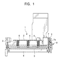
- FIG. 1 shows an example of a line-type thermal printer 1 which carries out the driving method of the paper-feeding stepping motor 7 according to the present invention.
- a pair of side frames 3 are mounted on the side faces of a printer body 2, and a long platen roller 4 is rotatably supported therebetween.
- a line thermal head 5 having an array of heating elements is supported so as to be moved closer to and further apart from the platen roller 4.
- the line thermal head 5 is provided with a plurality of head-pressing springs 6 for applying a pressing force toward the back side thereof.
- the paper-feeding stepping motor 7 is also mounted in the printer body 2.
- a delivery roller (not shown) is connected to a driving shaft 7a of the paper-feeding stepping motor 7 via a transmission gear train 8.
- the delivery roller takes thermal recording paper out of a paper tray (both not shown) and supplies the paper between the platen roller 4 and the line thermal head 5.
- the paper-feeding stepping motor 7 includes a stator 10 having first, second, third, and fourth magnetic poles (phases) A, B, C, and D spaced at 90 degrees, and a rotor 11 formed of a permanent magnet having N and S poles spaced at 180 degrees.
- the rotor 11 is linked with an output shaft (not shown).
- a first coil 12 is formed around the first and third magnetic poles A and C, and a second coil 13 is formed around the second and fourth magnetic poles B and D.
- phase current serving as a driving signal
- a magnetic field is established by the current, and an attractive or repulsive electromagnetic force is generated between the stator 10 and the rotor 11.
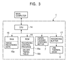
- feeding of the thermal recording paper and recording by the line thermal head 5 are controlled by a CPU 14 based on image recording data 15a and a recording control program 16a stored in a RAM 15 or a ROM 16, as shown in FIG. 3 as a block diagram. That is, the RAM 15 stores the image recording data 15a transmitted from a main computer.
- the ROM 16 stores the recording control program 16a for calculating the number of dynamic divisions based on the image recording data 15a.
- the ROM 16 also stores an on-off timing table 16b for the paper-feeding stepping motor 7 based on the number of divisions of an active pulse.
- duty ratios and pulse widths are preset in the on-off timing table 16b so as to subdivide an active pulse.
- an active pulse is instantaneously given in a predetermined subdivided form.
- the duty ratio means the ratio of the ON time of the HIGH pulses to a period for which the HIGH and LOW pulses are applied, that is, the duty cycle. Therefore, in this embodiment, when subdividing an active pulse, the duty ratio and the HIGH and LOW pulse widths thereof are set.
- FIG. 5 shows a procedure for expanding the image recording data 15a in this embodiment.
- Step ST1 the number of heating elements to be energized for one line is counted based on the image recording data 15a stored in the RAM 15, and is assigned to X.
- Step ST2 Z with remainder p is found by dividing the value X by a predetermined largest possible number Y of heating elements to be energized simultaneously.
- Step ST3 Z+p is set as the number of divisions N.
- image recording data 15a for one line is divided into N-number of line data, and is stored in a recording buffer 17 with the number of divisions N. The expansion of the image recording data 15a is thereby completed.
- the number of divisions N stored in the recording buffer 17 is fetched in Step ST11, and a subdivided state of an active pulse corresponding to the number of divisions N, that is, the ON time Ton and the OFF time Toff, are obtained by consulting the on-off timing table 16b of the paper-feeding stepping motor 7, in which the number of divisions N serves as a key, stored in the ROM 16 about the number of divisions N.
- Step ST13 the image recording data 15a is transferred to the line thermal head 5, and energization is started.
- Step ST14 a cycle, in which the paper-feeding stepping motor 7 is activated for the period Ton and is deactivated for the period Toff, is continued until the paper-feeding stepping motor 7 rotates one step. Recording of one line with the first color is thereby completed.
- the active pulse to be applied to the paper-feeding stepping motor 7 is subdivided into a predetermined duty ratio and a predetermined pulse width corresponding to the number of dynamic divisions, it is possible to optimally and smoothly shorten the energizing time of the motor, to inhibit an excessive increase of torque, to reduce noise, and to save energy.
- duty ratio and the pulse width corresponding to the number of divisions are found in a predetermined manner with reference to the on-off timing table 16b when subdividing the active pulse in this embodiment in order to attain quick processing, they may be found by operational expressions.
Landscapes
- Handling Of Sheets (AREA)
- Character Spaces And Line Spaces In Printers (AREA)
- Electronic Switches (AREA)
- Delivering By Means Of Belts And Rollers (AREA)
Abstract
Description
Claims (3)
- A paper-feeding stepping motor driving method in a thermal printer for driving a paper-feeding stepping motor for feeding recording paper in dynamic division printing in which the number of heating elements to be energized for recording each line with each color is found and divisional energization is performed so that the number of heating elements to be simultaneously energized is less than or equal to a predetermined number, wherein, while a driving signal to be applied to said paper-feeding stepping motor to be driven in response to the divisional energization of said heating elements is active, an active pulse is subdivided.
- A paper-feeding stepping motor driving method in a thermal printer according to Claim 1, wherein the active pulse is subdivided when the number of divisions for energization of said heating elements is more than or equal to two.
- A paper-feeding stepping motor driving method in a thermal printer according to Claim 1 or 2, wherein the active pulse is subdivided into a predetermined duty ratio and a predetermined pulse width corresponding to the number of divisions.
Applications Claiming Priority (2)
| Application Number | Priority Date | Filing Date | Title |
|---|---|---|---|
| JP2000181427A JP3909194B2 (en) | 2000-06-16 | 2000-06-16 | Driving method of stepping motor for conveyance |
| JP2000181427 | 2000-06-16 |
Publications (3)
| Publication Number | Publication Date |
|---|---|
| EP1164028A2 true EP1164028A2 (en) | 2001-12-19 |
| EP1164028A3 EP1164028A3 (en) | 2003-01-15 |
| EP1164028B1 EP1164028B1 (en) | 2004-09-15 |
Family
ID=18682362
Family Applications (1)
| Application Number | Title | Priority Date | Filing Date |
|---|---|---|---|
| EP01305107A Expired - Lifetime EP1164028B1 (en) | 2000-06-16 | 2001-06-12 | Method for driving paper-feeding stepping motor in thermal printer |
Country Status (8)
| Country | Link |
|---|---|
| US (1) | US6937261B2 (en) |
| EP (1) | EP1164028B1 (en) |
| JP (1) | JP3909194B2 (en) |
| KR (1) | KR100386004B1 (en) |
| CN (1) | CN1190003C (en) |
| AT (1) | ATE276110T1 (en) |
| DE (1) | DE60105496T2 (en) |
| TW (1) | TW521484B (en) |
Cited By (2)
| Publication number | Priority date | Publication date | Assignee | Title |
|---|---|---|---|---|
| US8011772B2 (en) | 2003-07-18 | 2011-09-06 | Seiko Epson Corporation | Liquid container |
| WO2015059447A1 (en) * | 2013-10-22 | 2015-04-30 | Videojet Technologies Inc. | Machine and method of operation |
Families Citing this family (2)
| Publication number | Priority date | Publication date | Assignee | Title |
|---|---|---|---|---|
| JP5526606B2 (en) * | 2009-05-28 | 2014-06-18 | ブラザー工業株式会社 | Printing device |
| CN105915133B (en) * | 2016-04-19 | 2019-04-12 | 深圳星火自动化科技有限公司 | Stepper motor driver and its any divided method |
Family Cites Families (9)
| Publication number | Priority date | Publication date | Assignee | Title |
|---|---|---|---|---|
| JPS52141526A (en) * | 1975-10-27 | 1977-11-25 | Seiko Epson Corp | Voltage and temperature compensating control of thermal printer |
| JPS5797766A (en) * | 1980-12-10 | 1982-06-17 | Fuji Xerox Co Ltd | Copying machine |
| US4652806A (en) * | 1986-01-23 | 1987-03-24 | Aerotech, Inc. | Micro-stepping translator controller |
| JP3362448B2 (en) * | 1993-05-18 | 2003-01-07 | カシオ計算機株式会社 | Printing device |
| JP3258878B2 (en) * | 1994-12-02 | 2002-02-18 | セイコーエプソン株式会社 | Drive control method and apparatus for thermal head |
| JPH0965694A (en) * | 1995-08-29 | 1997-03-07 | Kofu Nippon Denki Kk | Variable current type motor driving control circuit |
| JP3656362B2 (en) * | 1997-05-20 | 2005-06-08 | セイコーエプソン株式会社 | Step motor driving method and driving apparatus |
| JP3412509B2 (en) | 1998-05-19 | 2003-06-03 | 松下電器産業株式会社 | Drive for thermal line printer |
| JP4137307B2 (en) * | 1999-08-26 | 2008-08-20 | セイコーインスツル株式会社 | Thermal line printer and driving method of thermal line printer |
-
2000
- 2000-06-16 JP JP2000181427A patent/JP3909194B2/en not_active Expired - Fee Related
-
2001
- 2001-05-18 TW TW090111980A patent/TW521484B/en active
- 2001-06-07 CN CNB011187018A patent/CN1190003C/en not_active Expired - Fee Related
- 2001-06-12 KR KR10-2001-0032701A patent/KR100386004B1/en not_active Expired - Fee Related
- 2001-06-12 EP EP01305107A patent/EP1164028B1/en not_active Expired - Lifetime
- 2001-06-12 AT AT01305107T patent/ATE276110T1/en not_active IP Right Cessation
- 2001-06-12 DE DE60105496T patent/DE60105496T2/en not_active Expired - Lifetime
- 2001-06-14 US US09/881,486 patent/US6937261B2/en not_active Expired - Fee Related
Cited By (3)
| Publication number | Priority date | Publication date | Assignee | Title |
|---|---|---|---|---|
| US8011772B2 (en) | 2003-07-18 | 2011-09-06 | Seiko Epson Corporation | Liquid container |
| WO2015059447A1 (en) * | 2013-10-22 | 2015-04-30 | Videojet Technologies Inc. | Machine and method of operation |
| US9656479B2 (en) | 2013-10-22 | 2017-05-23 | Videojet Technologies Inc. | Machine and method of operation |
Also Published As
| Publication number | Publication date |
|---|---|
| EP1164028B1 (en) | 2004-09-15 |
| KR100386004B1 (en) | 2003-06-02 |
| US20010052988A1 (en) | 2001-12-20 |
| DE60105496T2 (en) | 2005-09-29 |
| JP2001353917A (en) | 2001-12-25 |
| DE60105496D1 (en) | 2004-10-21 |
| KR20010113480A (en) | 2001-12-28 |
| CN1330448A (en) | 2002-01-09 |
| US6937261B2 (en) | 2005-08-30 |
| EP1164028A3 (en) | 2003-01-15 |
| TW521484B (en) | 2003-02-21 |
| JP3909194B2 (en) | 2007-04-25 |
| CN1190003C (en) | 2005-02-16 |
| ATE276110T1 (en) | 2004-10-15 |
Similar Documents
| Publication | Publication Date | Title |
|---|---|---|
| EP0765759B1 (en) | Printer device control device | |
| US6937261B2 (en) | Method for driving paper-feeding stepping motor in thermal printer | |
| JPS63112182A (en) | Printer device | |
| JP3813793B2 (en) | Driving method of stepping motor for conveyance | |
| JPH028908B2 (en) | ||
| JP3031063B2 (en) | Printing device | |
| JP3060178B2 (en) | Serial printer | |
| JP3201429B2 (en) | Printer | |
| JP2002059605A (en) | Shuttle control system for printer | |
| JP2002067413A (en) | Roll sheet printer | |
| JP2005186509A (en) | Line-type thermal printer and its divided drive method | |
| JP3362686B2 (en) | Motor control device | |
| JP2003092897A (en) | Driving control method for stepping motor, recording method for line thermal printer therewith, and line thermal printer | |
| JP3427390B2 (en) | Line printer | |
| JP2003289699A (en) | Motor drive control method and apparatus, and recording apparatus | |
| JPH063642U (en) | Thermal printer | |
| JPH08258359A (en) | Thermal serial printer | |
| JP3067736U (en) | Printer motor controller | |
| JPH0425147B2 (en) | ||
| JP2004230852A (en) | Thermal printer | |
| JP2021007296A (en) | Printer | |
| JP2001063104A (en) | Dot impact printer | |
| JP2000326561A (en) | Printing device shuttle control method | |
| JPH02273268A (en) | paper feed mechanism | |
| JPH11268342A (en) | Printer and control method thereof |
Legal Events
| Date | Code | Title | Description |
|---|---|---|---|
| PUAI | Public reference made under article 153(3) epc to a published international application that has entered the european phase |
Free format text: ORIGINAL CODE: 0009012 |
|
| AK | Designated contracting states |
Kind code of ref document: A2 Designated state(s): AT BE CH CY DE DK ES FI FR GB GR IE IT LI LU MC NL PT SE TR |
|
| AX | Request for extension of the european patent |
Free format text: AL;LT;LV;MK;RO;SI |
|
| PUAL | Search report despatched |
Free format text: ORIGINAL CODE: 0009013 |
|
| AK | Designated contracting states |
Kind code of ref document: A3 Designated state(s): AT BE CH CY DE DK ES FI FR GB GR IE IT LI LU MC NL PT SE TR |
|
| AX | Request for extension of the european patent |
Free format text: AL;LT;LV;MK;RO;SI |
|
| RIC1 | Information provided on ipc code assigned before grant |
Free format text: 7B 41J 11/42 A, 7B 41J 2/32 B, 7H 02P 8/22 B, 7B 41J 2/355 B |
|
| 17P | Request for examination filed |
Effective date: 20030221 |
|
| 17Q | First examination report despatched |
Effective date: 20030422 |
|
| AKX | Designation fees paid |
Designated state(s): AT BE CH CY DE DK ES FI FR GB GR IE IT LI LU MC NL PT SE TR |
|
| GRAP | Despatch of communication of intention to grant a patent |
Free format text: ORIGINAL CODE: EPIDOSNIGR1 |
|
| GRAS | Grant fee paid |
Free format text: ORIGINAL CODE: EPIDOSNIGR3 |
|
| GRAA | (expected) grant |
Free format text: ORIGINAL CODE: 0009210 |
|
| AK | Designated contracting states |
Kind code of ref document: B1 Designated state(s): AT BE CH CY DE DK ES FI FR GB GR IE IT LI LU MC NL PT SE TR |
|
| PG25 | Lapsed in a contracting state [announced via postgrant information from national office to epo] |
Ref country code: FI Free format text: LAPSE BECAUSE OF FAILURE TO SUBMIT A TRANSLATION OF THE DESCRIPTION OR TO PAY THE FEE WITHIN THE PRESCRIBED TIME-LIMIT Effective date: 20040915 Ref country code: NL Free format text: LAPSE BECAUSE OF FAILURE TO SUBMIT A TRANSLATION OF THE DESCRIPTION OR TO PAY THE FEE WITHIN THE PRESCRIBED TIME-LIMIT Effective date: 20040915 Ref country code: TR Free format text: LAPSE BECAUSE OF FAILURE TO SUBMIT A TRANSLATION OF THE DESCRIPTION OR TO PAY THE FEE WITHIN THE PRESCRIBED TIME-LIMIT Effective date: 20040915 Ref country code: LI Free format text: LAPSE BECAUSE OF FAILURE TO SUBMIT A TRANSLATION OF THE DESCRIPTION OR TO PAY THE FEE WITHIN THE PRESCRIBED TIME-LIMIT Effective date: 20040915 Ref country code: CH Free format text: LAPSE BECAUSE OF FAILURE TO SUBMIT A TRANSLATION OF THE DESCRIPTION OR TO PAY THE FEE WITHIN THE PRESCRIBED TIME-LIMIT Effective date: 20040915 Ref country code: BE Free format text: LAPSE BECAUSE OF FAILURE TO SUBMIT A TRANSLATION OF THE DESCRIPTION OR TO PAY THE FEE WITHIN THE PRESCRIBED TIME-LIMIT Effective date: 20040915 Ref country code: AT Free format text: LAPSE BECAUSE OF FAILURE TO SUBMIT A TRANSLATION OF THE DESCRIPTION OR TO PAY THE FEE WITHIN THE PRESCRIBED TIME-LIMIT Effective date: 20040915 |
|
| REG | Reference to a national code |
Ref country code: CH Ref legal event code: EP Ref country code: GB Ref legal event code: FG4D |
|
| REG | Reference to a national code |
Ref country code: IE Ref legal event code: FG4D |
|
| REF | Corresponds to: |
Ref document number: 60105496 Country of ref document: DE Date of ref document: 20041021 Kind code of ref document: P |
|
| PG25 | Lapsed in a contracting state [announced via postgrant information from national office to epo] |
Ref country code: GR Free format text: LAPSE BECAUSE OF FAILURE TO SUBMIT A TRANSLATION OF THE DESCRIPTION OR TO PAY THE FEE WITHIN THE PRESCRIBED TIME-LIMIT Effective date: 20041215 Ref country code: DK Free format text: LAPSE BECAUSE OF FAILURE TO SUBMIT A TRANSLATION OF THE DESCRIPTION OR TO PAY THE FEE WITHIN THE PRESCRIBED TIME-LIMIT Effective date: 20041215 Ref country code: SE Free format text: LAPSE BECAUSE OF FAILURE TO SUBMIT A TRANSLATION OF THE DESCRIPTION OR TO PAY THE FEE WITHIN THE PRESCRIBED TIME-LIMIT Effective date: 20041215 |
|
| PG25 | Lapsed in a contracting state [announced via postgrant information from national office to epo] |
Ref country code: ES Free format text: LAPSE BECAUSE OF FAILURE TO SUBMIT A TRANSLATION OF THE DESCRIPTION OR TO PAY THE FEE WITHIN THE PRESCRIBED TIME-LIMIT Effective date: 20041226 |
|
| REG | Reference to a national code |
Ref country code: CH Ref legal event code: PL |
|
| NLV1 | Nl: lapsed or annulled due to failure to fulfill the requirements of art. 29p and 29m of the patents act | ||
| PG25 | Lapsed in a contracting state [announced via postgrant information from national office to epo] |
Ref country code: IT Free format text: LAPSE BECAUSE OF NON-PAYMENT OF DUE FEES Effective date: 20050612 Ref country code: LU Free format text: LAPSE BECAUSE OF NON-PAYMENT OF DUE FEES Effective date: 20050612 Ref country code: CY Free format text: LAPSE BECAUSE OF FAILURE TO SUBMIT A TRANSLATION OF THE DESCRIPTION OR TO PAY THE FEE WITHIN THE PRESCRIBED TIME-LIMIT Effective date: 20050612 |
|
| PG25 | Lapsed in a contracting state [announced via postgrant information from national office to epo] |
Ref country code: IE Free format text: LAPSE BECAUSE OF NON-PAYMENT OF DUE FEES Effective date: 20050613 |
|
| PG25 | Lapsed in a contracting state [announced via postgrant information from national office to epo] |
Ref country code: MC Free format text: LAPSE BECAUSE OF NON-PAYMENT OF DUE FEES Effective date: 20050630 |
|
| ET | Fr: translation filed | ||
| PLBE | No opposition filed within time limit |
Free format text: ORIGINAL CODE: 0009261 |
|
| STAA | Information on the status of an ep patent application or granted ep patent |
Free format text: STATUS: NO OPPOSITION FILED WITHIN TIME LIMIT |
|
| 26N | No opposition filed |
Effective date: 20050616 |
|
| REG | Reference to a national code |
Ref country code: IE Ref legal event code: MM4A |
|
| PG25 | Lapsed in a contracting state [announced via postgrant information from national office to epo] |
Ref country code: PT Free format text: LAPSE BECAUSE OF NON-PAYMENT OF DUE FEES Effective date: 20050215 |
|
| PGFP | Annual fee paid to national office [announced via postgrant information from national office to epo] |
Ref country code: FR Payment date: 20090605 Year of fee payment: 9 |
|
| REG | Reference to a national code |
Ref country code: FR Ref legal event code: ST Effective date: 20110228 |
|
| PG25 | Lapsed in a contracting state [announced via postgrant information from national office to epo] |
Ref country code: FR Free format text: LAPSE BECAUSE OF NON-PAYMENT OF DUE FEES Effective date: 20100630 |
|
| PGFP | Annual fee paid to national office [announced via postgrant information from national office to epo] |
Ref country code: GB Payment date: 20110523 Year of fee payment: 11 |
|
| PGFP | Annual fee paid to national office [announced via postgrant information from national office to epo] |
Ref country code: DE Payment date: 20110630 Year of fee payment: 11 |
|
| GBPC | Gb: european patent ceased through non-payment of renewal fee |
Effective date: 20120612 |
|
| REG | Reference to a national code |
Ref country code: DE Ref legal event code: R119 Ref document number: 60105496 Country of ref document: DE Effective date: 20130101 |
|
| PG25 | Lapsed in a contracting state [announced via postgrant information from national office to epo] |
Ref country code: DE Free format text: LAPSE BECAUSE OF NON-PAYMENT OF DUE FEES Effective date: 20130101 Ref country code: GB Free format text: LAPSE BECAUSE OF NON-PAYMENT OF DUE FEES Effective date: 20120612 |