EP1163833A1 - Axialtrennvorrichtung mit einer dem Auslassabschnitt zugeordneten Leiteinrichtung - Google Patents
Axialtrennvorrichtung mit einer dem Auslassabschnitt zugeordneten Leiteinrichtung Download PDFInfo
- Publication number
- EP1163833A1 EP1163833A1 EP01114058A EP01114058A EP1163833A1 EP 1163833 A1 EP1163833 A1 EP 1163833A1 EP 01114058 A EP01114058 A EP 01114058A EP 01114058 A EP01114058 A EP 01114058A EP 1163833 A1 EP1163833 A1 EP 1163833A1
- Authority
- EP
- European Patent Office
- Prior art keywords
- rotor
- leading edge
- axial
- separating device
- guide
- Prior art date
- Legal status (The legal status is an assumption and is not a legal conclusion. Google has not performed a legal analysis and makes no representation as to the accuracy of the status listed.)
- Granted
Links
- 238000011144 upstream manufacturing Methods 0.000 claims description 8
- 238000007599 discharging Methods 0.000 claims description 3
- 238000000926 separation method Methods 0.000 description 6
- 239000010902 straw Substances 0.000 description 6
- 239000000463 material Substances 0.000 description 4
- 238000004140 cleaning Methods 0.000 description 3
- 238000009826 distribution Methods 0.000 description 3
- 230000007704 transition Effects 0.000 description 2
- 239000012141 concentrate Substances 0.000 description 1
- 238000003306 harvesting Methods 0.000 description 1
- 238000011084 recovery Methods 0.000 description 1
Images


Classifications
-
- A—HUMAN NECESSITIES
- A01—AGRICULTURE; FORESTRY; ANIMAL HUSBANDRY; HUNTING; TRAPPING; FISHING
- A01F—PROCESSING OF HARVESTED PRODUCE; HAY OR STRAW PRESSES; DEVICES FOR STORING AGRICULTURAL OR HORTICULTURAL PRODUCE
- A01F7/00—Threshing apparatus
- A01F7/02—Threshing apparatus with rotating tools
- A01F7/06—Threshing apparatus with rotating tools with axles in line with the feeding direction ; Axial threshing machines
Definitions
- the invention relates to an axial separation device for a Axial combine, with a rotor that has an outlet section for discharging crop, and with one of the outlet section assigned guide device for guiding the rotor skipped crop, which is provided with a leading edge.
- Agricultural combines are great machines that Harvest, thresh, separate and clean agricultural goods.
- the cleaned grain obtained in this way is in a combine harvester arranged grain tank saved.
- the cleaned grain can then by an unloading screw conveyor onto a truck, Trailer or placed in another receptacle.
- Axial combines have one or two large rotor-shaped axial ones Good processing units along the longitudinal axis of the Combine are arranged to thresh the harvested crop and separate. These axial crop processing units are included a loading section for receiving harvested crops, one Threshing section for threshing the feed section obtained goods, a separation section for releasing grain, the threshed material obtained from the threshing section is still included, and an outlet section for discharging the Goods freed from grain from the axial crop processing unit fitted.
- the harvested crop is transferred to the loading section by a Feeder fed.
- the good is in a good mat arranged, which the loading elements of the rotor of Pick up the processing unit and turn it into a helical one Spend river, d. H. have to rotate.
- the spiral flow of crop moves from Loading section to threshing section and then to Separating section. Due to the axial crop processing units Grain separated with chaff contained in the good by it through grids arranged on the bottom of the crop processing unit falls.
- the good outside the grain, such as straw, occurs from the separating section into the outlet section of the crop processing units on.
- the outlet section abuts the grain different goods then or at the back of the combine leads this good to the back of the combine arranged straw chopper.
- the object underlying the invention is seen in to provide a discharge arrangement that has a large Range of crops and crop conditions both very good Material discharge properties as well as a very good one Has transverse distribution.
- the housing of the axial separation device ends in the outlet section in a control facility.
- This guidance device has an after first leading edge swept down and one swept up second leading edge, as determined by the rotation of the rotor
- Axial separating device can be defined.
- the downside Leading edge and the leading edge facing upwards merge at a lower middle dead center of the guide device, which is arranged below the axis of rotation of the rotor.
- the invention suggests the first and second leading edges are so asymmetrical to design that the first leading edge in the axial direction of the Rotor is opened further (i.e. located further forward) than that second leading edge. So the downside of the Rotors a larger free - d. H. not from the guiding element covered - assigned to the cross section of the shaft in which the Flows well downwards / backwards. At the first leading edge, this can be done Flow past more easily than at the second leading edge.
- d. H. that of the downward-facing side of the First leading edge assigned to the rotor over the longitudinal extent of the Guide element to the bottom middle dead center of the guide element continuous, d. H. is always in the axial direction of the rotor arranged further forward, the closer it is to the dead center.
- the the upward-facing side of the rotor adjacent, second Leading edge can extend over its longitudinal extent from the lower middle dead center of the guide element outwards and upwards close continuously, d. H. always placed further back his. In particular, it makes sense that the down swept leading edge opens at a slower rate than the leading edge turned up closes.
- the discharge chute can have an inclined floor, one behind side wall swept down and one swept up Sidewall.
- the side wall turned down can have an upstream wall and a downstream arranged wall.
- the upstream wall extends preferably from the bottom middle dead center of the Guide to the downstream plate. Both the upstream as well as the downstream plate can extend backward and transverse to the forward direction, with the downstream plate to a greater extent extends rearward as the upstream plate.
- the after side wall swept up also extends from the lower middle dead center across and back.
- FIG. 1 shows an agricultural combine 10 with a chassis 12 and extending therefrom Ground wheels 14. Although the combine 10 with wheels 14 is shown, it could also be with two or four tracks be equipped.
- a crop recovery device 16 is used to pick up crop and feed it to a feeder 18 feed. The crop is one from the feeder 18 Guide drum 20 supplied. The guide drum 20 guides the crop up through an inlet transition area 22 to one Axial separating device 24 further. All refer below Directional information (such as front, back, cross) on the Combine 10 forward travel direction.
- the axial separator 24 threshes and separates the harvested Good. Grain and chaff fall through grates at the bottom of the Axial separating device 24 in a cleaning system 26.
- Das Cleaning system 26 removes the chaff and performs the clean Grain to a grain elevator (not shown).
- the grain elevator places the clean grain in a grain tank 28.
- the clean grain in the grain tank 28 can by a discharge screw 30 on a Trailers or trucks are unloaded.
- Threshed, grain-free straw is made from the Axial separator 24 through an outlet 32 to one Dispensing drum 34 led out.
- the delivery drum 34 throws again the straw at the rear end of the combine 10. It should be noted that the discharge drum 34 is the grain Feed the freed crop directly to a straw chopper could.
- the combine 10 is operated by a Driver cabin 35 out.
- the axial separating device 24 comprises a cylindrical one Rotor housing 36 and a rotor arranged in rotor housing 36 37.
- the forward parts of the rotor 37 and the rotor housing 36 define the loading section 38 the axial separating device 24.
- the rotor 37 is in the loading section 38 with a conical rotor drum with spiral helical Feeding elements for collecting crops from the Guide drum 20 and the inlet transition region 22 added is equipped.
- threshing section 39 of the axial separating device 24 Immediately downstream of the loading section 38 is the threshing section 39 of the axial separating device 24.
- the rotor 37 comprises a cylindrical one Rotor drum 49 with a number of threshing elements in order to Thresh the crop received by the loading section 38 becomes.
- Downstream of the threshing section 39 is the Separation section 40, in which the grain caught in the crop is released and through a bottom grate in the Cleaning system 26 falls.
- the separating section 40 goes into one Outlet section 41 over where crop that contains no grain is ejected from the axial separator 24.
- the outlet section 41 of the axial separation device 24 is shown in FIG Figure 2 best shown.
- the in the separating section 40 and The outlet section 41 arranged area of the rotor 37 is with Good engagement elements 50 equipped.
- This section of the Rotor 37 and the arrangement of the good engagement elements 50 is in Separation section 40 and in the outlet section 41 equal to one Tearing the helical flow of the grain-freed Minimize crops.
- the Rotor 37 clockwise so that the right side of the Rotor housing 36 the downward side 52 and the left Side of the rotor housing 36 is the upward side 54.
- the outlet section 41 is provided with a guide device 56 provided that adapted to the curvature of the rotor 37 and above projecting out of a discharge chute 58 (protruding into it) is arranged.
- the discharge chute 58 is inclined Bottom 60, one of the downward side 52 of the rotor 37 associated side wall 62 and one of the upward facing Side 54 of the rotor 37 facing side wall 64.
- the inclined floor 60 extends down and leads the transversely arranged delivery drum 34 crop.
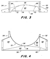
- the projecting guide device 56 has one of the downward first leading edge 70 adjacent the opposite side 52 of the rotor 37 and one of the upward side 54 of the rotor 37 adjacent, second leading edge 72, the lower middle Dead center 74 of the guide device 56 meet one another.
- the Guide 56 has a unique asymmetrical shape. in the Individual is that of the downward side 52 of the rotor 37 associated leading edge 70 opens further and opens ever further (i.e. it is always further ahead), ever closer to the bottom center dead center 74 of the guide is. That of the upward-facing side 54 of the rotor 37 assigned leading edge 72 closes from the lower middle Dead center 74 of the guide device 56 in the upward direction and increasing outside, d. H. it is gradually further back arranged.
- This unique asymmetric guide 56 distributes that Grain-cleared goods more evenly across the width of the cross dispensing drum 34 disposed.
- the opens assigned to the downward-facing side 52 of the rotor 37 Leading edge 70 of the guide device 56 quickly (in its Viewed from outside to inside) to eject of the goods in the downward side of the discharge shaft 58 to favor. That of the downward facing page 52 assigned leading edge 70 of the guiding device 58 opens slowly and continuously until it reaches the lower middle Dead center 74 of the guide device 56 is reached.
- the control device 58 closes in the area of the upward-facing side 54 assigned leading edge 72 faster than in the area of the after below associated side 52 leading edge 70 so that the Flow of crop to the upside of the Discharge shaft 58 is performed.
- the good that is on the leading edge 72 is led past that of the upward-facing side 54 is assigned, is carried around by the rotor 37 and on the after ejected below side of the discharge shaft 58.
- the reference to the lower middle dead center 74 of the guide device 58 here refers to a general area and not a specific point.
Landscapes
- Life Sciences & Earth Sciences (AREA)
- Environmental Sciences (AREA)
- Threshing Machine Elements (AREA)
- Combined Means For Separation Of Solids (AREA)
- Refuse Receptacles (AREA)
- Sampling And Sample Adjustment (AREA)
- Closures For Containers (AREA)
- Cyclones (AREA)
Abstract
Description
- Fig. 1
- eine Seitenansicht eines landwirtschaftlichen Mähdreschers mit einer axial angeordneten Gutbearbeitungseinheit mit einem Rotor,
- Fig. 2
- eine rückwärtige perspektivische Ansicht des Auslassabschnitts der axialen Gutbearbeitungseinheit,
- Fig. 3
- eine Draufsicht auf die Leiteinrichtung und den Austragschacht, und
- Fig. 4
- eine rückseitige Ansicht der Leiteinrichtung und des Austragsschachts.
Claims (11)
- Axialtrennvorrichtung (24) für einen Axialmähdrescher (10), mit einem Rotor (37), der einen Auslassabschnitt (41) zum Auslassen von Erntegut aufweist, und mit einer dem Auslassabschnitt (41) zugeordneten Leiteinrichtung (56) zum Führen des vom Rotor (37) ausgelassenen Ernteguts, die mit einer Leitkante (70, 72) versehen ist, dadurch gekennzeichnet, dass die Leiteinrichtung (56) eine erste Leitkante (70), die der nach unten drehenden Seite (52) des Rotors (37) benachbart ist, und eine zweite Leitkante (72) aufweist, die der nach oben drehenden Seite (54) des Rotors (37) benachbart ist und unterhalb der Drehachse des Rotors (37) auf die erste Leitkante (70) trifft, wobei die Leiteinrichtung (56) unsymmetrisch ist und die erste Leitkante (70) eine größere Öffnung bereitstellt als die zweite Leitkante (72).
- Axialtrennvorrichtung (24) nach Anspruch 1, dadurch gekennzeichnet, dass der Rotor (37) einen Trennabschnitt (40) aufweist, in dem Guteingriffselemente (50) angeordnet sind, die gleichartig mit im Auslassabschnitt (41) angeordneten Guteingriffselementen (50) sind.
- Axialtrennvorrichtung (24) nach Anspruch 1 oder 2, dadurch gekennzeichnet, dass sich die erste Leitkante (70) von einem unteren mittleren Totpunkt (74) unterhalb der Drehachse des Rotors (37) über ihre Länge nach außen kontinuierlich weiter nach hinten schließt.
- Axialtrennvorrichtung (24) nach einem der Ansprüche 1 bis 3, dadurch gekennzeichnet, dass sich die zweite Leitkante (72) von einem unteren mittleren Totpunkt (74) unterhalb der Drehachse des Rotors (37) über ihre Länge nach außen kontinuierlich weiter nach hinten schließt.
- Axialtrennvorrichtung (24) nach Anspruch 4, dadurch gekennzeichnet, dass sich die erste Leitkante (70) zumindest über den Hauptteil ihrer Länge langsamer schließt als die zweite Leitkante (72).
- Axialtrennvorrichtung (24) nach einem der Ansprüche 1 bis 5, dadurch gekennzeichnet, dass der Auslassabschnitt (41) unterhalb der Leiteinrichtung (56) mit einem Austragschacht (58) versehen ist.
- Axialtrennvorrichtung (24) nach Anspruch 6, dadurch gekennzeichnet, dass der Austragschacht (58) mit einem sich nach unten neigenden Boden (60), einer der nach unten gekehrten Seite (52) des Rotors (37) zugeordneten Seitenwand (62) und einer der nach oben gekehrten Seite (54) des Rotors (37) zugeordneten Seitenwand (64) ausgestattet ist.
- Axialtrennvorrichtung (24) nach Anspruch 7, dadurch gekennzeichnet, dass die der nach unten gekehrten Seite (52) des Rotors (37) zugeordnete Seitenwand (62) mit einer stromauf angeordneten Platte (66) und einer stromab angeordneten Platte (68) versehen ist.
- Axialtrennvorrichtung (24) nach Anspruch 8, dadurch gekennzeichnet, dass sich die stromauf angeordnete Platte (66) und die stromab angeordnete Platte (68) nach hinten und außen erstrecken, wobei sich die stromab angeordnete Platte (68) weiter nach hinten erstreckt als die stromauf angeordnete Platte (66).
- Axialtrennvorrichtung (24) nach einem der Ansprüche 1 bis 9, dadurch gekennzeichnet, dass die Leiteinrichtung (56) entsprechend dem Radius des Rotors (37) gekrümmt ist.
- Mähdrescher (10) mit einer Axialtrennvorrichtung (24) nach einem der vorhergehenden Ansprüche.
Priority Applications (1)
| Application Number | Priority Date | Filing Date | Title |
|---|---|---|---|
| DK01114058T DK1163833T3 (da) | 2000-06-15 | 2001-06-08 | Aksialsepareringsindretning med en til udlöbsafsnittet knyttet ledeindretning |
Applications Claiming Priority (2)
| Application Number | Priority Date | Filing Date | Title |
|---|---|---|---|
| US09/594,992 US6352474B1 (en) | 2000-06-15 | 2000-06-15 | Metering edge for axially arranged rotary separator |
| US594992 | 2000-06-15 |
Publications (2)
| Publication Number | Publication Date |
|---|---|
| EP1163833A1 true EP1163833A1 (de) | 2001-12-19 |
| EP1163833B1 EP1163833B1 (de) | 2005-02-16 |
Family
ID=24381254
Family Applications (1)
| Application Number | Title | Priority Date | Filing Date |
|---|---|---|---|
| EP01114058A Expired - Lifetime EP1163833B1 (de) | 2000-06-15 | 2001-06-08 | Axialtrennvorrichtung mit einer dem Auslassabschnitt zugeordneten Leiteinrichtung |
Country Status (7)
| Country | Link |
|---|---|
| US (1) | US6352474B1 (de) |
| EP (1) | EP1163833B1 (de) |
| AR (1) | AR032156A1 (de) |
| BR (1) | BR0102390B1 (de) |
| CA (1) | CA2343921C (de) |
| DE (1) | DE50105346D1 (de) |
| DK (1) | DK1163833T3 (de) |
Families Citing this family (7)
| Publication number | Priority date | Publication date | Assignee | Title |
|---|---|---|---|---|
| GB0106725D0 (en) * | 2001-03-19 | 2001-05-09 | Claas Selbstfahr Erntemasch | Combine harvester |
| US6830512B2 (en) * | 2002-07-19 | 2004-12-14 | Cnh America Llc | Shroud for the infeed impeller of a rotary combine |
| US7186179B1 (en) | 2005-08-15 | 2007-03-06 | Cnh America Llc | Adjustable flow deflector apparatus for transitioning crop residue flow from an axially arranged threshing system to a residue distribution system of an agricultural combine |
| US20080058042A1 (en) * | 2006-05-25 | 2008-03-06 | Isaac Nathan E | Rigid rotor discharge deflector |
| US7473169B2 (en) | 2007-02-28 | 2009-01-06 | Cnh America Llc | Adjustable axial rotor discharge deflector |
| EP2910107A1 (de) * | 2014-02-24 | 2015-08-26 | John Deere (Tianjin) Co., Ltd | Dresch- und Trennvorrichtung und Mähdrescher damit |
| US11832557B2 (en) * | 2018-04-11 | 2023-12-05 | Cnh Industrial America Llc | Rotational rotor discharge deflector |
Citations (2)
| Publication number | Priority date | Publication date | Assignee | Title |
|---|---|---|---|---|
| GB2032748A (en) * | 1978-10-31 | 1980-05-14 | White Motor Canada | Axial flow combine |
| EP1031270A1 (de) * | 1999-02-24 | 2000-08-30 | Deere & Company | Axialtrennvorrichtung für einen Mähdrescher |
Family Cites Families (3)
| Publication number | Priority date | Publication date | Assignee | Title |
|---|---|---|---|---|
| US3863643A (en) * | 1973-06-29 | 1975-02-04 | Int Harvester Co | Discharge chute and expansion chamber for an axial flow-type combine |
| DE2830164C3 (de) | 1978-07-08 | 1981-11-05 | Deere & Co., Niederlassung Deere & Co. European Office 6800 Mannheim, Moline, Ill. | Axial-, Dresch- und Trennvorrichtung für Mähdrescher |
| US5344367A (en) * | 1993-03-31 | 1994-09-06 | Deere & Company | Infeed plate for an axial agricultural combine |
-
2000
- 2000-06-15 US US09/594,992 patent/US6352474B1/en not_active Expired - Fee Related
-
2001
- 2001-04-11 CA CA002343921A patent/CA2343921C/en not_active Expired - Fee Related
- 2001-06-08 DE DE50105346T patent/DE50105346D1/de not_active Expired - Lifetime
- 2001-06-08 DK DK01114058T patent/DK1163833T3/da active
- 2001-06-08 EP EP01114058A patent/EP1163833B1/de not_active Expired - Lifetime
- 2001-06-13 BR BRPI0102390-0A patent/BR0102390B1/pt not_active IP Right Cessation
- 2001-06-14 AR ARP010102857A patent/AR032156A1/es active IP Right Grant
Patent Citations (2)
| Publication number | Priority date | Publication date | Assignee | Title |
|---|---|---|---|---|
| GB2032748A (en) * | 1978-10-31 | 1980-05-14 | White Motor Canada | Axial flow combine |
| EP1031270A1 (de) * | 1999-02-24 | 2000-08-30 | Deere & Company | Axialtrennvorrichtung für einen Mähdrescher |
Also Published As
| Publication number | Publication date |
|---|---|
| CA2343921C (en) | 2004-01-27 |
| CA2343921A1 (en) | 2001-12-15 |
| US6352474B1 (en) | 2002-03-05 |
| EP1163833B1 (de) | 2005-02-16 |
| AR032156A1 (es) | 2003-10-29 |
| BR0102390A (pt) | 2002-02-19 |
| DE50105346D1 (de) | 2005-03-24 |
| BR0102390B1 (pt) | 2009-01-13 |
| DK1163833T3 (da) | 2005-06-20 |
Similar Documents
| Publication | Publication Date | Title |
|---|---|---|
| DE69613379T2 (de) | Axialflussmähdrescher | |
| DE60013772T2 (de) | Entlandungsmittel für dresch-und trennvorrichtungseinheit eines mähdreschers | |
| DE602004005553T2 (de) | System zum Ausstossen von Ernteresten aus einem Mähdrescher | |
| EP1358789B1 (de) | Mähdrescher mit Strohhäcksler | |
| EP1020108B1 (de) | Rotor für einen Axialmähdrescher | |
| EP1421843B1 (de) | Mähdrescher mit Strohhäcksler | |
| EP2022310B1 (de) | Zwischen Breitverteil- und Auswurfkrümmerbetrieb umschaltbare Erntegutresteabgabeanordnung für einen Mähdrescher | |
| EP0958733B1 (de) | Rotor einer Axialtrennvorrichtung | |
| EP1031270B1 (de) | Axialtrennvorrichtung für einen Mähdrescher | |
| DE2462568A1 (de) | Dreschmaschine, insbesondere maehdrescher | |
| DE2729012A1 (de) | Maehdrescher | |
| EP2011384B1 (de) | Erntegutbearbeitungseinheit mit durchsatzabhängiger Umlaufzahl | |
| EP1226747B1 (de) | Leittrommel mit austauschbaren Mitnehmern | |
| EP1103176B1 (de) | Rotor einer Axialtrennvorrichtung | |
| DE102016217609B4 (de) | Mähdrescher mit Strohrutsche und Strohförderer | |
| EP0282736B1 (de) | Rückführeinrichtung für Mähdrescher | |
| EP1500323B1 (de) | Erntegutbearbeitungselement für einen Rotor einer Gutbearbeitungseinrichtung eines Mähdreschers | |
| EP1559306B1 (de) | Verteiler zur Verbesserung der Materialverteilung auf einem Sieb eines Reinigungssystems | |
| EP1163833B1 (de) | Axialtrennvorrichtung mit einer dem Auslassabschnitt zugeordneten Leiteinrichtung | |
| EP0095713B1 (de) | Erntemaschine mit einer Aufnahmevorrichtung | |
| EP1354508B1 (de) | Axialabscheider mit Leitschiene | |
| DE602004003542T2 (de) | Axialdreschmähdrescher mit adaptierbarer Trennvorrichtung | |
| DE102011088543B4 (de) | Mähdrescher mit einer zwischen der Drescheinrichtung und der Reinigung angeordneten Nachdrescheinrichtung | |
| BE1023629B1 (de) | Erntegutresteverteileinrichtung für einen Mähdrescher | |
| DE102008040128A1 (de) | Erntegutrestehäcksel und -verteilanordnung für einen Mähdrescher mit einem an die Kontur des Strohhäckslers angepassten Wurfgebläse |
Legal Events
| Date | Code | Title | Description |
|---|---|---|---|
| PUAI | Public reference made under article 153(3) epc to a published international application that has entered the european phase |
Free format text: ORIGINAL CODE: 0009012 |
|
| AK | Designated contracting states |
Kind code of ref document: A1 Designated state(s): DE DK FR GB IT Kind code of ref document: A1 Designated state(s): AT BE CH CY DE DK ES FI FR GB GR IE IT LI LU MC NL PT SE TR |
|
| AX | Request for extension of the european patent |
Free format text: AL;LT;LV;MK;RO;SI |
|
| 17P | Request for examination filed |
Effective date: 20020619 |
|
| AKX | Designation fees paid |
Free format text: DE DK FR GB IT |
|
| 17Q | First examination report despatched |
Effective date: 20031217 |
|
| GRAP | Despatch of communication of intention to grant a patent |
Free format text: ORIGINAL CODE: EPIDOSNIGR1 |
|
| GRAS | Grant fee paid |
Free format text: ORIGINAL CODE: EPIDOSNIGR3 |
|
| GRAA | (expected) grant |
Free format text: ORIGINAL CODE: 0009210 |
|
| AK | Designated contracting states |
Kind code of ref document: B1 Designated state(s): DE DK FR GB IT |
|
| REG | Reference to a national code |
Ref country code: GB Ref legal event code: FG4D Free format text: NOT ENGLISH |
|
| REG | Reference to a national code |
Ref country code: IE Ref legal event code: FG4D Free format text: GERMAN |
|
| REF | Corresponds to: |
Ref document number: 50105346 Country of ref document: DE Date of ref document: 20050324 Kind code of ref document: P |
|
| GBT | Gb: translation of ep patent filed (gb section 77(6)(a)/1977) |
Effective date: 20050319 |
|
| REG | Reference to a national code |
Ref country code: DK Ref legal event code: T3 |
|
| PLBE | No opposition filed within time limit |
Free format text: ORIGINAL CODE: 0009261 |
|
| STAA | Information on the status of an ep patent application or granted ep patent |
Free format text: STATUS: NO OPPOSITION FILED WITHIN TIME LIMIT |
|
| ET | Fr: translation filed | ||
| 26N | No opposition filed |
Effective date: 20051117 |
|
| PGFP | Annual fee paid to national office [announced via postgrant information from national office to epo] |
Ref country code: GB Payment date: 20140627 Year of fee payment: 14 |
|
| PGFP | Annual fee paid to national office [announced via postgrant information from national office to epo] |
Ref country code: IT Payment date: 20140624 Year of fee payment: 14 Ref country code: DE Payment date: 20140521 Year of fee payment: 14 |
|
| PGFP | Annual fee paid to national office [announced via postgrant information from national office to epo] |
Ref country code: DK Payment date: 20140625 Year of fee payment: 14 |
|
| PGFP | Annual fee paid to national office [announced via postgrant information from national office to epo] |
Ref country code: FR Payment date: 20140617 Year of fee payment: 14 |
|
| REG | Reference to a national code |
Ref country code: DE Ref legal event code: R119 Ref document number: 50105346 Country of ref document: DE |
|
| REG | Reference to a national code |
Ref country code: DK Ref legal event code: EBP Effective date: 20150630 |
|
| PG25 | Lapsed in a contracting state [announced via postgrant information from national office to epo] |
Ref country code: IT Free format text: LAPSE BECAUSE OF NON-PAYMENT OF DUE FEES Effective date: 20150608 |
|
| GBPC | Gb: european patent ceased through non-payment of renewal fee |
Effective date: 20150608 |
|
| REG | Reference to a national code |
Ref country code: FR Ref legal event code: ST Effective date: 20160229 |
|
| PG25 | Lapsed in a contracting state [announced via postgrant information from national office to epo] |
Ref country code: GB Free format text: LAPSE BECAUSE OF NON-PAYMENT OF DUE FEES Effective date: 20150608 Ref country code: DE Free format text: LAPSE BECAUSE OF NON-PAYMENT OF DUE FEES Effective date: 20160101 |
|
| PG25 | Lapsed in a contracting state [announced via postgrant information from national office to epo] |
Ref country code: FR Free format text: LAPSE BECAUSE OF NON-PAYMENT OF DUE FEES Effective date: 20150630 |
|
| PG25 | Lapsed in a contracting state [announced via postgrant information from national office to epo] |
Ref country code: DK Free format text: LAPSE BECAUSE OF NON-PAYMENT OF DUE FEES Effective date: 20150630 |