BACKGROUND OF THE INVENTION
(1) Field of the Invention:
The present invention relates to a network managing
method, a network node apparatus and a mesh-type network,
and more particularly to those suitable for optical fiber
communication network.
(2) Description of Related Art:
Nowadays, in an optical fiber communication network
(hereinafter also called "network"), voice data and other
data are transmitted in various protocols, such as STM
(Synchronous Transfer Mode), ATM (Asynchronous Transfer
Mode) or IP (Internet Protocol), using a transmission
system, such as SDH (Synchronous Digital Hierarchy) or
SONET (Synchronous Optical NETwork), as the core.
Further, as WDM (Wavelength Division Multiplexing)
technology advances, large-capacity optical fiber
communication networks have been realizing by
multi-wavelength multiplexing transmission, e.g.
64-wavelength or 128-wavelength.
In the meantime, as symbolized by recent expansion
of the Internet, with an increasing data traffic and a
growing variety of services, it is becoming more
significant that the optical fiber communication network
has to be large in capacity and, in addition, to meet
various demands, such as reliability of network and
control matching the service. It is also becoming
essential to flexibly cope with the increasing capacity
(due to addition of a node and addition of a wavelength)
after the network has been constructed.
Paying attention to the reliability of network, the
optical fiber communication network according to SONET
or SDH is exemplified, as an automatic restoring network
being aimed at traffic protection during occurrence of
a trouble, by a line-type 1+1 switched network by MSP
(Multiplex Section Protection)/APS (Automatic
Protection Switch) and a ring-type network, such as
2F-BLSR (2-Fiber-Bi-directional Line Switched Ring),
4F-BLSR or UPSR (Uni-directional Path Switched Ring),
all standardized by a standardization organization, such
as ITU-T (International Telecommunication Union-Telecommunication
sector).
The line-type 1+1 switched network and the 2F-BLSR
network will now be generally described as examples.
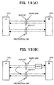
First of all, in the line-type 1+1 switched network,
as shown in FIG. 13(A) of the accompanying drawings, a
pair of physical lines (optical fibers) 300 is disposed
between confronting node apparatuses (hereinafter also
called "nodes") 100, 200; during normal operation, one
physical line is used as a work line 300(W), and the other
physical line is kept idle to be used as a protection
line 300 (P). When a trouble happens to occur in the work
line 300(W), as shown in FIG. 13(B), the line being used
is switched to the protection line 300 (P) to protect the
traffic.
The line switching at that time is carried out by
transmitting/receiving switching control information
called APS byte (K1, K2 byte), which is standardized in
the section overhead (SOH) of an SDH/SONET frame, between
the individual node apparatuses 100 and 200 through the
protection line 300(P).
In the meantime, the 2F-BLSR network is composed,
as shown in FIGS. 14(A) and 14(C), plural node apparatuses
(four node apparatuses designated by A through D in FIG.
14(A) ) connected one to another in a ring-shaped pattern
by a pair of physical lines (optical fibers) 500, (for
STM-16 (2.4 Gb/s) in FIG. 14(C)) one in each of EAST and
WEST directions.
Further, in the 2F-BLSR network, one half of region
of the individual optical fiber 500 (E, W) is allocated
to work channels and the other half is allocated to
protection channels (for example, in STM-16, CH. 1-8 of
CH. 1-16 are work channels, and the remaining CH. 9-16
are protection channels) . If a trouble has occurred in
the physical line 500 between a pair of particular nodes
(the node apparatuses "B"-"C" in FIG. 14(B)), a signal
is bridged to the protection channel in the reverse
direction to detour around a trouble point, thus relieving
the traffic.
In the case of 4F-BLSR network, two sets of work
and protection optical fibers ( four in total) are prepared
one set for each of EAST and WEST directions instead of
dividing the individual optical fiber, thereby switching
the lines in units of optical fibers. And in the case
of UPSR network, the same signal is rendered to flow in
both EAST and WEST directions to make the line redundant.
But in either case, line switching, such as bridging is
controlled at the node apparatus based on K1, K2 bytes
in SOH.
However, the foregoing existing optical fiber
communication network would encounter the following
problems:
Assuming that the optical fiber communication
network is a mesh-type network other than the
above-mentioned ring- and line-type networks, a new node
can be located (added) in an arbitrary place, but no optimal
restoring system for a mesh-type network is standardized
intheexistingSDH/SONETsystem. Consequently, the only
way to actually construct a mesh-type network using the
existing system is to combine the line-type network and
the ring-type (4F-BLSR in FIG. 15) as shown in FIG. 15.
However, this hypothetical mesh-type network is
a mere composite network of line- and ring-type networks,
and therefore the half of the line (channels) must be
emptied for protection like the existing ring- or
line-type network, which would be poor in line occupancy
efficiency. Originally a mesh-type network should be
restorable from a trouble without keeping a half of the
entire line capacity idle.
Assuming that a line trouble has occurred between
nodes "A" and "E" as shown in FIG. 15, it is inevitable
to use a protection line between the nodes "A" and "E"
because a partial network between "A" and "E" is a line-type
network. As an alternative, an idle channel of another
route, such as the nodes "A"-"B"-"E" or the nodes
"A"-"C"-"E" may be used.
But in the line route such as the nodes "A"-"B"-"E"
or the nodes "A"-"C"-"E", though a physical line
connection is provided, the restoring operation has to
be divided for a line-type switching region and a ring-type
switching region (restoring operation is uniform as
standardized according to Recommendation) . Practically,
therefore, it would be impossible to carry out line
switching, either transmitting a signal on the line-type
network using a route of the ring-type network or vice
versa.
As a consequence, if troubles have occurred one in
each of work and protection lines between the nodes "A"-"E",
it is impossible to relieve the traffic in despite of
a mesh-type structure. This is, with the existing system,
it is impossible to construct a high-redundancy
(trouble-resistance) network utilizing the original
characteristics of a mesh-type network.
SUMMARY OF THE INVENTION
With the foregoing problems in view, one object of
the present invention is to provide a network managing
method in which setting/managing a line route satisfying
a desired QoS (Quality of Service) can be performed
independently at the individual node apparatuses, which
constitute a network, with ease and flexibleness,
drastically improving a redundancy (resistance to
hindrance) of the line route irrespective of the current
system such as SDH or SONET.
Another object of the invention is to provide a
network node apparatus as one of the plural network node
apparatuses which constitute the network to be managed
by the above-mentioned method.
Still another object of the invention is to provide
a mesh-type network to be managed by the above-mentioned
method.
To attain the above object (s), according to a generic
feature of the present invention, there is provided a
network node apparatus for use in a network composed of
plural node apparatuses, comprising: a managing section
for managing network QoS (Quality of Service) information
about quality of service for possible signal transmission
routes in a network, the network QoS information being
to be obtained as accumulation of inter-neighboring-node
QoS information about QoS between neighboring node
apparatuses; and a control section for controlling an
operation of selecting one of the possible signal
transmission routes in said network node apparatus itself
based on the network QoS information being managed by
the managing section. The network node apparatus will
hereinafter be also called "node". The plural nodes are
interconnected in a mesh pattern to construct a mesh-type
network.
In this network, the network QoS information for
the candidate signal transmission routes (hereinafter
also called "signal route") in the network is managed
at the individual nodes. At the individual node, a route
selection by the self node is determined based on the
network QoS information being managed by the self node.
Namely, it is possible to select an arbitrary signal
route or routes satisfying a desired network QoS
information, among candidate signal routes in the network,
independently at the individual node.
Therefore it is possible to flexibly control the
setting of signal routes according to a desired QoS for
the network, realizing a variety of controls according
to desired communication services, such as setting of
redundancy of an arbitrary signal route or setting of
a bi-directional signal route using an arbitrary signal
route.
Preferably, the managing section may include the
following:
Given that each node is provided with these sections,
it is possible to transmit the inter-neighboring-node
QoS information between the individual nodes while the
information is accumulated as the signal travels around
the successive nodes on the route.
Therefore, a complicated, enormous setting work,
which would have occasionally required setting of
information to be managed with respect to the individual
nodes takes place, is unnecessary, thus greatly reducing
an amount of personal work as by the operator.
As another preferred feature, the managing section
may have an ID information adding unit for adding unique
ID information, which is assigned to the node apparatus
itself, to a signal to be transmitted to the neighboring
node apparatus, and a route identifying unit responsive
to the signal transmission signal from the neighboring
node apparatus to identify the individual signal
transmission route in terms of a combination of plural
pieces of the ID information sequentially added to the
transmission signal. With this arrangement, since the
individual node can recognize the signal route from a
received signal, it is possible to simply grasp, at the
individual node, the number of signal routes in the network
up to the self node. It is therefore possible to retrieve
candidate signal routes in the network with maximum ease.
As still another preferred feature, the managing
section may have a combination information creating/
managing unit for creating/managing combination
information about combinations each of the identified
signal transmission route and the network QoS information
corresponding to the identified signal transmission route.
With this arrangement, it is possible to easily retrieve
a route satisfying a particular network QoS information,
amount all signal routes in the network, thus enabling
a variety of route settings.
As a further preferred feature, the managing section
may have a route setting unit for selecting, from the
signal transmission routes being created/managed by said
combination information creating/managing unit in terms
of the combination information, an arbitrary signal
transmission route, which satisfies a required network
quality of service, as a substitute signal transmission
route for providing desired communications service,
thereby making a setting of signal transmission route
in the network.
Further, since information about the combination
of the thus grasped route and the network QoS information
of the route is created/managed, it is possible to
facilitate retrieving/setting a route satisfying a
particular network QoS information, among all candidate
signal routes in the network. And since a variety of route
settings are possible, it is possible to realize
setting/managing the route according to desired QoS with
maximum ease.
BRIEF DESCRIPTION OF THE DRAWINGS
FIG. 1 is a block diagram schematically showing a
mesh-type optical fiber communication network according
to one embodiment of the present invention;
FIG. 2 is a diagram showing one example of optical
channel container to be used in the digital wrapper
transmission system;
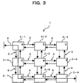
FIG. 3 is a block diagram illustrating
inter-neighboring-node QoS (Quality of Service)
information (q) and network QoS information (Q) in the
present embodiment;
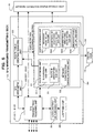
FIG. 4 is a block diagram schematically showing a
detailed construction of the individual node of FIG. 1;
FIG. 5 is a block diagram schematically showing a
detailed construction of a Q/q managing/sending section
of FIG. 4;
FIG. 6 is a block diagram illustrating the operation
(route quality q collecting/determining operation) of
the mesh-type optical fiber communication network of FIG.
1;
FIG. 7 is a block diagram illustrating one example
of status in which the route quality q has been determined
in the mesh-type optical fiber communication network of
FIG. 1;
FIG. 8 is a block diagram illustrating the operation
(redundancy setting and line route switching operation)
of the mesh-type optical fiber communication network of
FIG. 1;
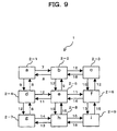
FIG. 9 is a block diagram illustrating one example
of status in which the route quality q has been determined
in the mesh-type optical fiber communication network of
FIG. 1;
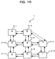
FIG. 10 is a block diagram schematically showing
the mesh-type optical fiber communication network of FIG.
1 in which a node has been removed;
FIG. 11 is a block diagram schematically showing
the mesh-type optical fiber communication network of FIG.
1 in which a node has been added;
FIG. 12 is a block diagram illustrating a
modification of the inter-neighboring-node
communication;
FIG. 13 (A) is a block diagram schematically showing
an existing line-type 1+1 switching network;
FIG. 13(B) is a block diagram illustrating the
operation of the network of FIG. 13(A) when a hindrance
has occurred;
FIG. 14 (A) is a block diagram schematically showing
an existing ring-type network (2F-BLSR);
FIG. 14(B) is a block diagram schematically
illustrating the operation of the network of FIG. 14 (A)
when a hindrance has occurred;
FIG. 14(C) is a diagram schematically showing how
to allocate work channels and protection channels by band
division in FIG. 14(A); and
FIG. 15 is a block diagram schematically showing
a mesh-type optical communication network constructed
by combining the existing line-type 1+1 switching network
and the ring-type network.
DESCRIPTION OF THE PREFERRED EMBODIMENT
One embodiment of the present invention will now
be described with reference to the accompanying drawings.
FIG. 1 is a block diagram schematically showing a
mesh-type optical fiber communication network 1 according
to one embodiment of the present invention. The mesh-type
optical fiber communication network 1 is constructed by
a plurality of network node apparatuses 2-1 through 2-N
(N is an integer equal to or larger than 2, N=9 in FIG.
1) which are bi-directionally communicably
interconnected by physical lines 3(hereinafter called
"transmission path 3") such as optical fibers. These
network node apparatuses 2-1 through 2-N are according
to a signal transmission system such as SDH (Synchronous
Digital Hierarchy), SONET (Synchronous Optical NETwork)
or Digital Wrapper.
Assume that node IDs (identification information,
which is represented by a through i for convenience),
each unique in the whole globe, such as MAC (Media Access
Control) address, are allocated one to each of the nodes
2-i (i=1 to N) . In the following description, the nodes
2-1 through 2-9 are expressed as the nodes a through i,
respectively.
Studies on "Digital Wrapper" are on the rise as WDM
(Wavelength Division Multiplexing) technology has
growingly become popular in recent years. The Digital
Wrapper is a rather new signal transmission system in
an optical fiber communication network, this technology
enables a signal transmission that could not have been
realized with the existing transmission systems such as
SDH, SONET, STM, ATM and IP.
Specifically, the signal frame structure of "Digital
Wrapper", which is also called "Optical Channel Container",
is generally similar to that of SDH or SONET, as shown
in FIG. 2. Namely, a single optical channel container
7 includes an optical channel overhead (Och-OH) section
4, an optical channel payload envelope (Och-PE) section
5, and a forward error correction (FEC) data section 6.
In the Och-OH section 4, information, such as for
various kinds of maintenance operation framing bytes (OA1,
OA2 bytes) is stored; in the Och-PE section 5, various
kinds of signals as of SDH, SONET, ATM or IP are stored;
and in the FEC data section 6, data for error correction
is stored. Having this frame structure, "Digital
Wrapper" realizes a signal transmission that could not
have been expected by the existing transmission systems.
In other words, a node suitable for "Digital Wrapper"
has a function to send/receive a signal with the
above-mentioned frame structure. In the following
description, it is assumed that each and every node 2-i
is a node suitable for "Digital Wrapper", and that the
mesh-type optical fiber communication network
(hereinafter also called "mesh-type network" and simply
"network") of "Digital Wrapper" is constructed by these
nodes 2-i.
In the network 1 of the present embodiment, as line
switching factors in the above-mentioned line-type
network or ring-type network, "network QoS information
(Q)" and "inter-neighboring-node QoS information (q)"
are defined in addition to information (e.g., Loss of
Signal, Loss of Frame) defined by Standardization
Institute, such as ITU-T and Bellcore, and quality
information (e.g., B1, B2 bytes). And these two kinds
of QoS information are stored in the optical channel
container 7 (e.g., in an unused area of the Och-OH section
4, and are transmitted between the individual nodes 2-i
so that each node 2-i can independently perform a line
route setting (signal routing) operation in accordance
with an intended QoS while monitoring QoS, under no central
control as by the known NMS (Network Management System) .
The term "network QoS information (Q)" represents
information about QoS in a region from a particular
start-point node 2-i to end-point node 2-i (e.g., from
the node a to the node i in FIG. 1) in the network 1 (i.e.,
a region from the entrance to the exit in the network
1. The term "inter-neighboring-node QoS information
(q)" in the meantime represents information about QoS
between neighboring nodes 2-i. The network QoS
information (Q) and the inter-neighboring-node QoS
information (q) will hereinafter also called "route
quality Q" and "route quality q".
Therefore, for example, as shown in FIG. 3, as
attention is paid to the
line route 8 via the nodes a,
d, g, h, i, among candidate signal transmission routes
(line routes) establishable between the node a and the
node i, it turns out that the route quality Q of the
line
routes 8 can simply be obtained by accumulating (addition)
the route qualities q of four neighboring-
node regions
9, i.e., between the nodes a-d, the nodes d-g, the nodes
g-h and the nodes h-i, which jointly constitute the
line
route 8. Namely, the relation between the route quality
Q and the route quality q can be expressed by the following
formula (1):
where n is the number of (inter-neighboring-node) regions
via which a signal travels from a starting point to an
end point. The route quality qk can be expressed by the
following formula (2).
where bp is the numerical value information relating QoS
contained in the route quality qk, m is the number of
parameters (bp) relating the route quality q, and ap is
the weighting coefficient with respect to the parameter
bp. Assuming that the above-mentioned parameters (bp)
are defined as five kinds of parameters (bl through b5)
indicated in the following Table 1, QoS information qk
between a particular pair of neighboring nodes is
expressed by the following formula (3).
| FACTORS OF INTER-NEIGHBORING-NODE QOS INFORMATION (q) |
| FACTOR | CONTENT | NEEDED DATA LENGTH | EXPRESSION |
| b 1 | TRANSMISSION LENGTH | 4 -BIT | ALLOCATE 0000-1111 KM AT 10 KM PITCH |
| b 2 | NO. OF NODES TO PASS | 6 -BIT | IN BINARY NOTATION |
| b 3 | LINE USE EFFICIENCY | 8 -BIT | IN BINARY NOTATION |
| b 4 | QUALITY | 4 -BIT | BER (E.G.) IS QUANTITATED, AND EXPRESSED IN BINARY NOTATION |
| b 5 | REDUNDANCY | 2 -BIT | NO. SELECTABLE AS REDUNDANT ROUTE IS EXPRESSED IN BINARY NOTATION |
qk=al*(transmission distance b1)+a2*(number
of on-route nodes b2)+a3*(line occupying
efficiency b3)+a4*(quality b4)+a5*b5
(redundancy) It turns out from the above formula (3) that if the
weighting coefficient (ap) with respect to a particular
parameter (bp) is large, the value of q is such a value
as to treat the parameter (bp) significant.
Namely, for setting a line route short in
transmission distance, an increased weighting
coefficient al suffices, and for setting a line route
less in number of on-route nodes, an increased weighting
coefficient a2. Likewise, for setting a line route good
in line occupying efficiency, an increased weighting
coefficient a3 suffices; for setting a line route good
in communication quality, an increased weighting
coefficient a4 suffices; and for setting a line route
high in redundancy, an increased weighting coefficient
a5 suffices.
These individual weighting coefficients (ap) can
be manually set, for example, by an operator as described
later. Namely, an operator can set a line route satisfying
a desired quality of service (condition) (QoS), such as
"transmission distance", "number of on-route nodes",
"line occupying efficiency", "communication quality" and
"redundancy". "line occupying efficiency" may be
obtained as an average of values within a predetermined
period.
In the present embodiment, assuming that the route
qualities Q and q obtained in the above-mentioned manner
are stored in unused areas of the Och-OH section 4 in
the above-mentioned optical channel container 7, they
can be transmitted between the individual nodes 2-i in
the network 1.
In order to realize the foregoing functions, the
individual node 2-i of the present invention, as shown
in FIG. 4, is equipped with an optical transport section
11 for every route direction (four route directions here) ,
and a number of optical interface sections 10 as many
as physical lines accommodated in each optical transport
section 11. The individual node 2-i is also equipped with
a switch 12, a switch controller 13, a Q/q managing/sending
section 14, and a network connection status storage
section 15.
Each optical interface section 10 accommodates an
optical fiber 2 to interface with the optical transport
section 11. Further, each optical interface section 10
has a function (network construction change detecting
section 110) to detect deletion of a neighboring node
2-i in the network 1, and also to detect addition of a
new neighboring node 2-i by receiving a signal from such
new neighboring node.
Each optical transport section 11 terminates/
disassembles an input optical signal (optical channel
container 7) from the respective self-accommodated
optical interface section 10, takes out data, which is
stored in the Och-PE section 5, to send the data to the
switch 12. Reversely, the data switched over by the switch
12 is stored in the Och-PE section 5 to assemble the optical
channel container 7 so that the data is sent to a
transmission path 2 via a predetermined optical interface
section 10.
For this purpose, each optical transport section
11, as shown in FIG. 4, is equipped with a frame
assembling/disassembling section 111 where
termination/insertion process of the Och-OH section 4
for an optical signal in each direction and an error
correction process using data of an FEC data section 6
are performed.
In the present embodiment, in the frame
assembling/disassembling section 111, the route quality
Q or the route quality q sent from the Q/q managing/sending
section 14 is inserted in an unused area of the Och-OH
section 4 at the optical channel container 7, and reversely,
the route quality Q or the route quality q inserted in
the Och-OH section 4 is extracted and is sent to the Q/q
managing/sending section 14.
The switch 12 outputs an optical signal, which is
input in an arbitrary direction (optical transport section
11), to an arbitrary direction (optical transport section
11). The switch controller (control section) 13 controls
an switching operation (signal routing operation) of the
switch 12 in accordance with an instruction (line route
setting) based on the information (route quality Q) being
managed by the Q/q managing/sending section 14.
The Q/q managing/sending section (managing section)
14 manages/sends the "network QoS information (Q)" about
possible all line routes in the network 1 and the
"inter-neighboring-node QoS information (q)"between the
self node 2-i and a neighboring node 2-i.
For this purpose, as its main components, as shown
in FIG. 5, the Q/q managing/sending section 14 includes
a Q/q sending/receiving sub-section 21, a Q/q arithmetic
sub-section 22, a route table creating/managing
sub-section 23, a route retrieving/determining
sub-section 24, q collecting/determining sub-section 25,
and a q setting sub-section 26.
The Q/q sending/receiving sub-section 21 transmits
the route qualities q of the self node 2-i, which have
been collected and determined by the q collecting/
determining sub-section 25, or the result of accumulating
arithmetic operation of the route qualities q by the Q/q
arithmetic sub-section 22 to all the neighboring nodes
2-i via the frame assembling/disassembling section 111
of the optical transport section 11. Further, the Q/q
sending/receiving sub-section 21 transmits the route
quality Q, which has been obtained by the Q/q arithmetic
sub-section 25, or the route quality Q, which has been
received from the neighboring node 2-i, to all the
neighboring nodes 2-i via the frame assembling/
disassembling section 111.
Namely, the Q/q sending/receiving sub-section 21
servers not only as an inter-neighboring-node QoS
information (q) transmitter 211 but also as a network
QoS information (Q) transmitter 212.
The Q/q arithmetic sub-section 22 obtains the route
qualities q and the route quality Q by arithmetic operation.
Precisely, the route qualities q or Q are obtained by
executing the accumulation arithmetic operations of the
formulae (1) and (2) by adding the route quality q of
the self node 2-i and the route quality q of the neighboring
node 2-i received from the neighboring node 2-i, or the
result of the accumulation arithmetic operations of the
route qualities q at the neighboring nodes 2-i.
Namely the Q/q arithmetic sub-section 22 serves not
only as a q (inter-neighboring-node QoS information)
arithmetic sub-section 221, which obtains the route
quality q by an accumulation arithmetic operation of both
the route quality q between the self node 2-i and the
neighboring node 2-i and the route quality q sent from
the neighboring node 2-i, but also as a Q (network QoS
information) arithmetic sub-section 222, which obtains
the route quality Q by an accumulation arithmetic
operation of both the route quality q of the self node
2-i and the result of the accumulation arithmetic
operation of the route qualities q sent from the
neighboring node 2-i.
The route table creating/managing sub-section
(combination information creating/managing section) 23
creates/manages combination information (route table)
about the combination of a line route, which is to be
identified by a later-described route retrieving unit
31 in the route retrieving/determining sub-section 24,
and Q with respect to the line route. The created "route
table" is stored and managed in the network connection
status storage section 15. This "route table", as
described later, will be recreated at each node 2-i in
accordance with a change of network construction due to
deletion or addition of a node 2-i.
Further, the route retrieving/determining
sub-section 24 retrieves (identifies) a possible line
route in the network 1 up to the self node 2-i, and
discriminates as to which line route satisfies a desired
route quality, whereupon the route
retrieving/determining sub-section 24 selects and sets
a line route to be used for providing a desired
communication service.
For this purpose, the route retrieving/determining
sub-section 24 includes the route retrieving unit 31,
a route determining unit 32, and a network construction
change notifying unit 33. The route retrieving unit 31
has an ID adding sub-unit 311 and a route ID identifying
sub-unit 312. The route determining unit has a redundant
line route setting sub-unit 321, a symmetrical
bi-directional line route setting sub-unit 322, an
asymmetrical bi-directional line route setting sub-unit
323, and a broadcast line route setting sub-unit 324.
First of all, in the route retrieving sub-section
31, the ID adding sub-unit (ID information adding
sub-unit) 311 sends a node ID, which is allocated to the
self node 2-i, to the optical transport section 11 (frame
assembling/disassembling section 111) via the Q/q
sending/receiving section 21 to add the node ID to a
transmission signal between the self node 2-i and the
neighboring node 2-i. The ID adding sub-unit 311 adds
an identifier (route ID), which is a combination of node
IDs, for example, "ab" to a signal having traveled through
the node a → the node b, and "abc" to a signal having
traveled through the node a → the node b → the node c.
The route ID identifying sub-unit (route identifying
unit) 312 identifies a line route, along which a signal,
as received, has traveled, by the route ID added to the
received signal. If the route ID of the received signal
is "ab", the signal is identified as a signal having
traveled along a line route through the nodes a and b;
otherwise if the route ID of the received signal is "abc",
the signal is identified as a signal having traveled along
a line route through the nodes a, b and c.
In the meantime, in the route determining unit (route
setting unit) 32, the redundancy line route setting
sub-unit (redundancy route setting unit) 321 sets
(selects) a desired route quality Q, which satisfies an
arbitrary line route, among the above-identified
candidate line routes being managed by the route table
creating/managing sub-section, based on the above-mentioned
route table, thereby setting a redundancy of
the line route in the network 1.
And the symmetrical bi-directional line route
setting sub-unit (symmetrical bi-directional
communication setting unit) 322 selects the same line
route, among the candidate line routes being managed by
the route table creating/managing sub-section 23, as a
signal transmission route for bi-directional
communication, thereby setting a symmetrical
bi-directional line route in the network 1.
Further, the asymmetrical bi-directional line route
setting sub-unit (asymmetrical bi-directional
communication setting unit) 323 selects upward and
downward line routes, which are different from each other,
among the candidate line routes being managed by the route
table creating/managing sub-section 23, as a line route
for bi-directional communication, thereby setting an
asymmetrical bi-directional line route in the network
1.
Furthermore, the broadcast line setting sub-unit
(broadcast communication setting unit) 324 selects
different line routes, among the candidate line routes
being managed by the route table creating/managing
sub-section 23, as a transmission route of the same signal,
thereby performing setting for broadcast communication
in the network 1.
Thus in the network 1 (node 2-i) of the present
embodiment, settings for various communication services,
such as setting of redundancy of a line route, setting
of a symmetrical/asymmetrical bi-directional line route
and setting for broadcast communication, can simply
performed based a common "route table".
Further, the network construction change notifying
unit 33 notifies the fact that deletion/addition of a
neighboring node 2-i has been detected by the network
construction change detecting section 110 associated with
one optical interface section 10, to all the neighboring
nodes 2-i via all the remaining optical interface section
10, and instructs the route table creating/managing
sub-section 23 to update the created "route table" in
accordance with deletion/addition of the neighboring
nodes 2-i.
Then in FIG. 5, upon receipt of q collecting/
determining triggers from an external source by the
operator, the q collecting/determining sub-section 25
automatically collects node information about all
confronting (neighboring) optical interface sections 10,
which information is possessed by the self node 2-i, and
determines a route quality q of the self node 2-i. This
node information is stored and managed in the network
connection status storage section 15.
This automatic collecting process can be enabled/
disabled by an enable/disable setting. If the automatic
collecting process is disabled by the disable setting,
the operation can manually set by the q setting sub-section
26.
In this event, the operator can set an arbitrary
weighting coefficient ap as an arbitrary value by
instructing the q setting sub-section 26 to set/update
the value of the weighting coefficient ap with respect
to the parameter bp in the formula (2), and thereby can
set the route quality q with an arbitrary parameter bp
treated as significant, among the parameters bp relating
the above-mentioned q, as a route quality q of the self
node 2-i.
The operation of the thus constructed network 1
(nodes 2-i) of the present embodiment will now be described
in detail.
| TABLE OF ROUTES (NODES a → i ) |
| ROUTE ID | ROUTE QUALITY Q |
| [abcfi] | 47 |
| [abcfedghi] | 98 |
| [abefi] | 43 |
| [abedghi] | 72 |
| [abehi] | 50 |
| [adefi] | 44 |
| [adebcfi] | 72 |
| [adehi] | 51 |
| [adghebcfi] | 102 |
| [adghefi] | 74 |
| [adghi] | 51 |
As the result, the node i can easily retrieve a target
line route (optimal line route to be set in accordance
with Q) in the network 1 based on the "route table".
Assuming that the above-mentioned route quality q has
been determined with the weighting coefficient al with
respect the parameter b1 (distance to the neighboring
node 2-i) being increased and the weighting coefficients
a2 through a5 with respect to the remaining parameters
b2 through b5 being default values (e.g., a1=4, a2=1,
a3=1, a4=1, a5=1), it turns out from the above Table 2
that the route whose signal transmission distance is
shortest in the network 1 is a signal route in which route
identifier="abefi" and route quality Q=43.The thus obtained "route table" (route quality Q
for every line route) is transmitted from the node i to
all the neighboring nodes 2-i and is then transmitted
to all the nodes 2-i in the network 1 as if toppling over
like a row of dominos in the same manner as the
above-mentioned transmission of the route quality q, and
finally the same "route table" at all the nodes 2-i is
stored/managed in the storage section 15.Then, as the switching operation of the switch 12
is controlled by the switch controller 13 in such a way
that the nodes a, b, c, f and i assumes a status in which
a signal route with the route identifier="abefi" and Q=43
is selected as that for providing a desired communication
service, a line route in which the transmission distance
of the node a → the node b → the node c → the node f
→ the node i is a shortest is set in the network 1.Also the "route table" with respect the signal route
in the direction opposite to the above-mentioned signal
route, e.g. the signal route in the direction of the node
the node i → the node a, is created as the route quality
q determining process and the route identifying process,
which is responsive to the retrieving command (e.g., "from
NE:i, to NE:a") in the same manner as described above.
And at the individual node 2-i, the identical information
(route table, the route quality Q for every candidate
signal route between the node i → the node a) is
retained/managed in the storage section 15.As mentioned above, according to the present
invention, partly since the route quality Q for candidate
line routes in the network 1, which quality is obtained
as accumulated information of the route qualities q
between the neighboring nodes 2-i, is managed in every
node 2-i in the network 1, and partly since the individual
node 2-i determines a line route setting operation on
the self-node side based on the route quality Q ("route
table") being managed by the self node, it is possible
to set/manage a line route in accordance with a desired
QoS independently at each of the nodes 2-i, which
constitute the network 1, with ease and flexibleness.Therefore, it is possible to control the setting
of a line route in accordance with a desired QoS flexibly
without any restriction by the existing system such as
SDH or SONET, thus realizing a variety of controls in
accordance with intended communication services. For
example, as described later in detail, it is possible
to drastically improve redundancy (resistance to
hindrance) of an arbitrary line route in the network 1
by the line route redundancy setting based on the route
quality Q to thereby realizing a greatly increased degree
of reliability of the entire network 1. It is also
possible to set a symmetrical or asymmetrical
bi-directional line routes or a broadcast line route in
accordance with a desired QoS in the network 1 in a very
simple manner.Particularly in the present embodiment, partly since
the above-mentioned route quality Q is obtained by
transmitting the route qualities q between the individual
nodes 2-i while accumulating the route qualities q, and
partly since the obtained route quality Q is transmitted
between the individual nodes 2-i as information
(information for "route table") to be managed at the
individualnode2-i, a complicated, enormous setting work,
which would have occasionally required in a mesh-type
network 1 where setting of information to be managed with
respect to the individual node 2-i takes place, is
unnecessary, thus greatly reducing an amount of personal
work as by the operator.In addition, since at the individual node 2-i,
information needed to determine the route quality q can
be automatically collected/determined by the q
collecting/determining sub-section 25, it is possible
to reduce personal work, such as setting of necessary
information. This automatic collecting process can be
enabled/disabled by an enable/disable setting. If the
automatic collecting process is disabled by the disable
setting, the operation can manually set by the q setting
sub-section 26. Thus, it enables to set an optimal line
route (a target line) flexibly.Further, in the present embodiment, partly a unique
node ID is allocated to each node 2-i in the network 1,
and partly since at the sender-side node 2-i the node
ID allocated to the self node 2-i is added to a signal
sent to the neighboring node 2-i by the ID adding sub-unit
311 (FIG. 5), it is possible to identify, at the
receiver-side node 2-i, the transmission route of the
signal in terms of the combination of the node IDs (route
ID) added to the received signal from the neighboring
node 2-i, thus identifying candidate line routes in the
network 1. It is therefore possible to realize not only
a candidate line route retrieving process in the mesh-type
network 1 with maximum ease, but also creating/managing
of "route table" by the route table creating/managing
sub-section 23 in a very simple manner. (3) Redundancy-Setting Line Route:
How to redundancy-set a line route will now be
described.Assume that a protection line route is set for a
signal route in which the above-mentioned route
identifier="abefi" and the route quality Q=43. In this
case, firstly at the individual 2-i, the redundant line
route setting sub-unit 321 of the route determining unit
32 sorts the above-mentioned Table 2 according to the
smallness of the route quality Q as indicated in the
following Table 3.
| TABLE OF ROUTES (NODES a → i) |
| PRECEDENCE | ROUTE ID | ROUTE QUALITY Q |
| 1. | [abefi] | 43 |
| 2. | [adefi] | 44 |
| 3. | [abcfi] | 47 |
| 4. | [abehi] | 50 |
| 5. | [adehi] | 51 |
| 5. | [adghi] | 51 |
| 6. | [abedghi] | 72 |
| 6. | [adebcfi] | 72 |
| 7. | [adghefi] | 74 |
| 8. | [abcfedghi] | 98 |
| 9. | [adghebcfi] | 102 |
From this Table 3, it can be judged that an optimal
redundant line route for the target (shortest transmission
distance) line route (route quality Q=43) is a second-shortest-transmission-distance
line route (route
quality Q=44, route identifier="adefi"). Therefore, as
shown in FIG. 8, if this signal route (route quality Q=44,
route identifier="adefi") is previously set as a
protection line route (detour route) 42 for the line route
(original route) 41 (route quality Q=43, route
identifier="abefi") by the redundant line route setting
sub-unit 321, it is possible to make an instant changeover
(detour) to the optimal (short transmission distance)
detour route 42 when a trouble has occurred (between the
nodes a and b in FIG. 8) in the original route 41.Assuming that a trouble has actually occurred
between a particular pair of nodes 2-i, the occurrence
of the trouble is detected at the neighboring nodes 2-i
of the section where the trouble has occurred (e.g., the
individual nodes a and b if the trouble has occurred in
the section between the nodes a and b) , and the occurrence
of the trouble is then notified to all the nodes 2-i in
the network as if toppling over like a row of dominos
in the same manner.Then at the node 2-i having been notified of the
occurrence of the trouble, the route determining unit
32 automatically selects an detour route 42 having the
optimal route quality Q, among candidate routes going
round about the section where the trouble has occurred
(in this case, the line route whose route ID does not
contain "ab"), based on the above-mentioned "route table"
being managed by the self node. Based on this selection,
the switch controller 13 controls the switching operation
of the switch 12 to change the line route (reselection
or rerouting of the line route) to a detour route.Namely, at the individual node 2-i on the original
route 41, the use of the original route 41 is stopped,
while at the individual node 2-i on the detour route 42,
the detour route 42 is validated by a setting such as
to transmit the received signal to the interface 10
connected to the neighboring node 2-i on the detour route
42. As the result, the detour tour 42 becomes conductive
as a substitution for the original route 41, finalizing
the line route switching.Thus in the present embodiment, since a redundancy
of a line route in the network is set by selecting an
arbitrary line route, which satisfying a desired QoS,
among candidate line routes being identified/managed
according to the "route table", as a protection route
of the arbitrary line route, it is possible to repeatedly
set a redundancy route in the network 1, thus remarkably
improving the reliability of the network 1.Since all the nodes 2-i in the network 1 retain/manage
the same "route table" as mentioned above, no
contradiction would occur in route change between the
nodes 2-i. At that time, at the node 2-i on the detour
route, it is possible to confirm, by the route ID
identifying sub-unit 312 from the route ID attached to
the received signal, whether the signal is received
exactly from the detour route. Otherwise if the route
ID of the received signal has been changed, the node 2-i
can recognize that a change has occurred in the line route
due to the occurrence of a trouble on the line route along
which the received signal travels.Alternatively, the occurrence of the trouble may
be detected by a non-illustrated network managing
apparatus, such as NMS (Network Management System), and
the section where the occurrence of the trouble may be
notified to the individual nodes from the network managing
apparatus. (4) Setting of Bi-directional Line Route:
How to set a bi-directional line route in the network
1 will now be described.Assume that a bi-directional (two-way) line route
is set between the nodes a and i. In this case, firstly
the operator inputs a command, which means "set a
bi-directional (two-way) line route between the nodes
a and i", to the node 2-i in the network 1. As this command
is finally received by the node a, not only the route
in the direction of the node a (start point of the signal)
→ the node i as mentioned above in the item (2), but also
the route in the reverse direction (of the node i → the
node a) starting from the node i, like the route of the
of the node a → the node i is retrieved.Accordingly, at the node i, it is possible to create
the "route table" for the direction of the node a → the
node i, while at the node a, it is possible to create
the "route table" for the reverse direction. As these
"route tables" are transmitted respectively at the
individual nodes 2-i , a bi-directional "route table"
between the nodes a and i is retained and managed by every
node 2-i in the network 1.Therefore, if at the individual node 2-i, the route
determining unit 32 selects a line route, which has an
optimal target route quality Q, as a line route to be
used, a bi-directional line route (communication line)
having the optimal target route quality Q is automatically
set independently in each direction (between the nodes
a and i) in the network 1.Assuming that, as shown in FIG. 7, the route qualities
q between the individual nodes 2-i have the same value
for the two directions, the route qualities Q of all the
line route also have the same value for the two directions.
Therefore, as the line route having an optimal target
route quality Q is selected, the same line route is selected
as a bi-directional communication line.In the case of FIG. 7, for example, partly since
the "route table" for the direction of the node a → the
node i is shown in the above Table 3, and partly since
the "route table" for the direction of the node i → the
node a is shown in the following Table 4, it is possible
to set the line route having the route quality Q=43 and
the route ID="abefi" and the line route having the route
quality Q=43 and the route ID="ifeba" as a shortest target
bi-directional communication line.
| TABLE OF ROUTES (NODES i → a ) |
| PRECEDENCE | ROUTE ID | ROUTE QUALITY Q |
| 1. | [ifeba] | 43 |
| 2. | [ifeda] | 45 |
| 3. | [ifcba] | 47 |
| 4. | [ihega] | 50 |
| 5. | [ihgda] | 51 |
| 6. | [iheda] | 52 |
| 7. | [ifcbeda] | 70 |
| 8. | [ihgdeba] | 72 |
| 9. | [ifehgda] | 75 |
| 10. | [ifcbehgda] | 100 |
| 11. | [ihgdefcba] | 103 |
Otherwise, as shown in FIG. 9, if a section in which
the route quality q for the interface 10 between the
neighboring nodes 2-i has different values between the
upward and downward routes of a bi-directional line route,
the same value should by no means be selected (set) for
both the direction of the node a → the node i and the
direction of the node i → the node a as a bi-directional
communication line.Namely, in the case of FIG. 9, partly since the "route
table" for the direction of the node a → the node i is
shown in the following Table 5, and partly since the "route
table" for the direction of the node i → the node a is
shown in the following Table 6, the optimal (shortest)
target line route for the direction of the node a → the
node i is a line route having the route quality Q=43 and
the route ID="abefi" as shown in Table 5. And the optimal
target line route for the reverse direction is a line
route having the route quality Q=47 and the route
ID="ihgda" as shown in Table 6. Thus asymmetrical line
routes are set as a bi-directional communication line.
| TABLE OF ROUTES (NODES a → i ) |
| PRECEDENCE | ROUTE ID | ROUTE QUALITY Q |
| 1. | [abefi] | 43 |
| 2. | [adefi] | 45 |
| 3. | [abcfi] | 47 |
| 4. | [abehi] | 50 |
| 5. | [adghi] | 51 |
| 5. | [adehi] | 52 |
| 6. | [adebcfi] | 71 |
| 6. | [adedghi] | 72 |
| 7. | [adghefi] | 75 |
| 8. | [adghebcfi] | 100 |
| 9. | [abcfedghi] | 103 |
| TABLE OF ROUTES (NODES i → a ) |
| PRECEDENCE | ROUTE ID | ROUTE QUALITY Q |
| 1. | [ihgda] | 47 |
| 2. | [ifeba] | 48 |
| 3. | [ifeda] | 50 |
| 4. | [iheba] | 51 |
| 5. | [ifcba] | 53 |
| 5. | [iheda] | 53 |
| 6. | [ihgdeba] | 68 |
| 7. | [ifehgda] | 75 |
| 8. | [ifcbeda] | 76 |
| 9. | [ihgdefcba] | 100 |
| 10. | [ifcbehgda] | 101 |
In other words, by comparing the two "route tables"
for the bi-directional line route, it is possible to
discriminate that or not the route qualities q between
all the neighboring nodes 2-i are available. Namely, if
the route qualities Q for total eleven line routes have
the same value for the bi-directional communication line,
it is possible to judge that the route qualities q between
all the neighboring nodes 2-i in the network 1 are
symmetrical for the bi-directional communication line.
Therefore, in this case, line routes traveling quite the
same route having the optimal route quality Q between
the nodes a and i are set (selected) as a bi-directional
communication line so that a "symmetrical" bi-directional
communication line is set (between the nodes a and i)
in the network 1. Otherwise if the result of comparison of the route
qualities Q are different for the upward and downward
routes as shown in Tables 6 and 7, it is possible to judge
that the route qualities q between the neighboring nodes
2-i for the upward and downward routes are asymmetrical.
Therefore, in this case, two line routes having different
optimal route qualities Q are respectively set (selected)
for the upward and downward routes so that an
"asymmetrical" bi-directional communication line is set
(between the nodes a and i) in the network 1.In the network 1, if such "asymmetrical" two-way
route is set, it is possible to disperse the load of traffic
in the network 1 with a risk that line management might
be complicated. To this end, it is preferable that a
symmetrical two-way route can be set (by force) also when
the route qualities q between the neighboring nodes 2-i
are asymmetrical for the upward and downward routes.Consequently, in the present embodiment, the route
table creating/managing sub-section 23 obtains the sum
of the route qualities Q of the upward and downward
directions for the same line route (i.e., Q1+Q2 where
Q1 is the route quality Q for the direction of the node
a → the node i, and Q2 is the route quality Q for the
reverse direction (direction of the node i → the node
a)), whereupon a symmetrical two-way route having the
optimal target route quality Q1+Q2 is set based on the
obtained sum of the two route qualities Q. Namely, if the route qualities q between the
neighboring nodes 2-i are as shown in FIG. 9, the individual
node 2-i creates a "route table (2-way route)" of the
following Table 7 based on the above Tables 5 and 6. As
the result, it is possible to judge that the two line
routes having the same route quality Q1+Q2=91 and the
route ID="abefi", "ifeba" are the optimal line routes
as a symmetrical two-way line so that a bi-directional
communication line is set between the nodes a and i.
| TABLE OF ROUTES (2-WAY ROUTE) |
| ROUTE ID (a → i ) | Q1 | ROUTE ID (i → a) | Q2 | Q1+Q2 | PRECEDENCE |
| [abefi] | 43 | [ifeba] | 48 | 91 | 1 |
| [adefi] | 45 | [ifeda] | 50 | 95 | 2 |
| [abcfi] | 47 | [ifcba] | 53 | 100 | 3 |
| [abehi] | 50 | [iheba] | 51 | 101 | 4 |
| [adghi] | 51 | [ihgda] | 47 | 101 | 4 |
| [adehi] | 52 | [iheda] | 53 | 105 | 5 |
| [adebcfi] | 71 | [ifcbeda] | 76 | 147 | 7 |
| [adedghi] | 72 | [ihgdeba] | 68 | 140 | 6 |
| [adghefi] | 75 | [ifehgda] | 75 | 150 | 8 |
| [adghebcfi] | 100 | [ifcbehgda] | 101 | 201 | 9 |
| [abcfedghi] | 103 | [ihgdefcba] | 100 | 203 | 10 |
As mentioned above, in the present embodiment, at
the individual node 2-i, by a simple control such as to
select different line routes or identical line routes
satisfying target route quality Q, among the line routes
being identified/managed according to the "route table",
as line routes for bi-directional communication, it is
possible to set either an asymmetrical or symmetrical
2-way route suitable for a desired route quality Q in
the network 1 in a very simple, flexible manner. (5) Setting of Broadcast Line:
How to set a broadcast line in the network 1 will
now be described.With a line route having the route quality Q=43 and
route ID="abefi" being set in the network 1 as the shortest
target route, it is assumed that a broadcast communication
line for sending a signal, which is to be transmitted
on this line route, between the nodes g and h is set.It is assumed that, likewise the creation of the
"route table" for the direction of the node a → the node
i, the "route table" for all the routes (e.g., a route
starting at the node a) in the network 1 and has already
been retained/managed by all the nodes 2-i.In this situation, first of all, the operator inputs
a command, which means "send the content of the line route
flowing the node a → the node i also to the node h and
g for the target shortest route" (broadcast setting
command, e.g., "a → i, h, g"), to an arbitrary node 2-i
(e.g., the node a) in the network 1.When the above-mentioned command is received at the
node a, the broadcast line route setting sub-unit 324
of the route determining unit 32 consults the individual
"route tables" for the direction of the node a → the node
h and the direction of the node a → the node g, and
selects/determines optimal routes (shortest routes in
this case) for the direction of the node a → the node
h and the direction of the node a → the node g as the
target shortest routes for direction of the node a → the
node i. Then the switch controller 13 sets the switching
operation of the switch 12 based on the
selection/determination of the broadcast line route
setting sub-unit 324.The node a thereby can send the content of the line
route for the direction of the node a → the node i also
to the optimal route for both the direction of the node
a → the node h and the direction of the node a → the node
g. And the broadcast setting command is sequentially sent
to the next neighboring nodes (nodes to be set) 2-i on
the selected/determined line route so that the same
broadcast setting is performed also at the nodes 2-i to
be set.As the result, for the target shortest route in the
direction of the node a → the node i, the optimal
(shortest) broadcast setting for the direction of the
node a → the node g and the direction of the node a →
the node h is completed.Thus in the present embodiment, at each node 2-i,
it is possible to perform a broadcast communication
setting suitable for a desired route quality Q in the
network 1 by a simple control, i.e., selecting different
line routes satisfying the target route quality Q, among
the line routes being identified/managed according to
the "route table", as transmission route of the same
signal. (6) Operations to Cope with Network Construction
Changes:
How to cope with a network construction change due
to deletion of a particular node 2-i or addition of a
new node 2-i will now be described.
(6-1) If a node 2-i is deleted in the
network 1:
An example, as shown in FIG. 10, in which a node
c is deleted is considered. In this example, the nodes
b and f being connected to the node c to be deleted is
notified of the deletion as by inputting a command by
the operator. Upon receipt of the command, at the
individual node b, f, the network construction change
detecting unit 110 of the interface 10 connected to the
node c can detect that "neighboring node has been deleted".In response to this, the node b notifies the nodes
a, e of the above-mentioned deletion by the network
construction change notifying unit 33, and likewise the
node f notifies the nodes e, i of the same deletion. As
the individual node 2-i repeats this notifying process,
all of the individual nodes 2-i, in the network 1 recognize
of the deletion of the node c.Then, all the individual nodes 2-i, except the node
c having been deleted as recognized, delete the line route
in which the node c exists, in the "route table" possessed
by the self node 2-i (the line route whose route ID contains
node ID=c of the node c), and "route table" is recreated
based on the value of the route quality Q. Upon completion
of the recreation of the foregoing "route tables" at all
the individual nodes 2-i , the node c is actually removed
off the network 1.Also if any of the individual nodes 2-i except the
node c is deleted, the "route table" according to the
deletion of such node is recreated, in the same manner
as mentioned above in connection with the node c, before
that node is actually deleted. Further, if two or more
nodes 2-i are deleted, the line routes containing the
respective node IDs are deleted.As mentioned above, if a node is deleted in the
network, individual complicated setting works, which
would have occasionally required in a mesh-type network
1, are unnecessary, facilitating the management of line
routes in the network 1. It is possible to cope with
deletion of a node without recreating the "route table"
entirely.If connection with another node 2-i in the network
1 is performed using the interface 10 to be emptied after
deletion of a node (e.g., if the nodes b and f are connected
as indicated by dotted lines in FIG. 10), it is necessary
to recreate the "route table" entirely after the route
quality q/Q determination and the route retrieving before
the node deletion, because a new line route occurs. (6-2) If a new node 2-i is added in the network 1:
Reversely, how to cope with addition of a new node
2-i in the network 1 will now be described.It is assumed that a node j (node 2-10) having the
node ID=j has been added as a new node as shown in FIG.
11. In this case, at each of the nodes i and f to which
the new node j has been connected, the network construction
change detecting section 110 of the interface 10 detects
that the nodej has been added. In response to this, the
node i notifies every neighboring node 2-i (nodes h and
f) of "addition of node" via the interface 10 by the network
construction change notifying unit 33. Likewise the node
f notifies every neighboring node 2-i (nodes e and i)
of "addition of node".As this notifying process is repeated, every node
2-i in the network 1 recognizes the addition of the node
j . All the nodes 2-i that have thus recognized of addition
of the node j then assume a stand-by status to add
information (line route running through the node j, and
the route quality Q) of the node j to the "route table"
possessed by the self node 2-i.In this situation, as the above-mentioned route
quality Q determining process and the route retrieving
process are executed, the "route table" for which the
line route passing through the node j is considered is
created, and is retained/managed at every node 2-i in
the network 1. In this manner, even if a node is added
in the network 1, individual complicated setting works,
which would have occasionally required in a mesh-type
network 1, are unnecessary, facilitating the management
of line routes in the network 1.As mentioned above, in the present embodiment, since
the network construction change due to the node deletion
or the node addition can be simply coped with by
reconstructing the "route table" at each node 2-i, it
is possible to reconstruct the network 1 simply and freely.
It is therefore also possible to add or delete a node
2-i according to the increase and decrease of capacity
of the network 1. (7) Modification in Transmission of Route Quality
Q ("Route Table"):
In the previous example, an unused area of the Och-OH
section 4 in the optical channel container 7 is utilized
in transmitting the route quality Q ("route table")
between the nodes 2-i to cope with a transmission system
called "Digital Wrapper". Alternatively, if the
mesh-type network 1 is constructed as the existing network
such as SDH or SONET, an unused overhead area in SDH or
SONET transmission frame may be utilized to cope with
such network 1 with the same result.In other words, by utilizing an unused overhead area
in Digital Wrapper, SONET or SDH, it is possible to realize
a network management that flexibly controls a variety
of communication services, with keeping connectivity
(compatibility) with the existing apparatus and network,
namely, without depending on the difference in
transmission system such as SDH or SONET.As represented by OSC (Optical Supervisory Channel)
in WDM transmission, a sub-channel is occasionally used
for inter-node communication in the network 1. In such
case, this sub-channel also can be utilized in
transmission of the route quality Q ("route table") in
addition to an unused overhead area in the above-mentioned
optical channel container 7 or SDH/SONET transmission
frame.Namely, as schematically shown in FIG. 12, if a
primary signal channel 51 and a sub-channel 52 are used
in inter-node communication, data X (route quality Q)
is divided into data x and data y at the sender-side node
2-i; one data x is transmitted by means of an unused
overhead area of a signal to be transmitted on the main
signal channel 51, and the other data y is transmitted
by means of the sub-channel 52. And the receiver-side
node 2-i, operates based on both the data x to be received
through the main signal channel 41 and the data y to be
received through the sub-channel 52.Since communication traffic for transmitting the
route quality Q between the nodes is thereby dispersed,
it is possible to reduce the heaviness with respect to
the original communication traffic.The present invention should by no means be limited
to the illustrated embodiment, and various changes or
modifications may be suggested without departing from
the gist of the invention.