JP4070246B2 - Method and apparatus for optical bidirectional line switch type ring data communication system - Google Patents
Method and apparatus for optical bidirectional line switch type ring data communication system Download PDFInfo
- Publication number
- JP4070246B2 JP4070246B2 JP54423898A JP54423898A JP4070246B2 JP 4070246 B2 JP4070246 B2 JP 4070246B2 JP 54423898 A JP54423898 A JP 54423898A JP 54423898 A JP54423898 A JP 54423898A JP 4070246 B2 JP4070246 B2 JP 4070246B2
- Authority
- JP
- Japan
- Prior art keywords
- command
- wavelengths
- slave
- ring
- control channel
- Prior art date
- Legal status (The legal status is an assumption and is not a legal conclusion. Google has not performed a legal analysis and makes no representation as to the accuracy of the status listed.)
- Expired - Lifetime
Links
- 230000003287 optical effect Effects 0.000 title claims description 88
- 238000000034 method Methods 0.000 title claims description 16
- 230000002457 bidirectional effect Effects 0.000 title claims description 12
- 238000004891 communication Methods 0.000 title description 22
- 239000000835 fiber Substances 0.000 claims description 69
- 238000012544 monitoring process Methods 0.000 claims description 8
- 230000004044 response Effects 0.000 claims description 4
- 239000013307 optical fiber Substances 0.000 claims description 3
- 230000000977 initiatory effect Effects 0.000 claims 6
- 230000008878 coupling Effects 0.000 claims 3
- 238000010168 coupling process Methods 0.000 claims 3
- 238000005859 coupling reaction Methods 0.000 claims 3
- 238000012423 maintenance Methods 0.000 description 11
- 230000007246 mechanism Effects 0.000 description 7
- 230000005540 biological transmission Effects 0.000 description 5
- 238000010586 diagram Methods 0.000 description 5
- 230000008901 benefit Effects 0.000 description 4
- 238000013461 design Methods 0.000 description 4
- 238000007792 addition Methods 0.000 description 2
- 238000001514 detection method Methods 0.000 description 2
- 230000009977 dual effect Effects 0.000 description 2
- 230000000694 effects Effects 0.000 description 2
- 230000011664 signaling Effects 0.000 description 2
- 238000013459 approach Methods 0.000 description 1
- 230000015556 catabolic process Effects 0.000 description 1
- 230000008859 change Effects 0.000 description 1
- 238000006243 chemical reaction Methods 0.000 description 1
- 238000006731 degradation reaction Methods 0.000 description 1
- 230000001419 dependent effect Effects 0.000 description 1
- 238000003745 diagnosis Methods 0.000 description 1
- 238000005516 engineering process Methods 0.000 description 1
- 230000003370 grooming effect Effects 0.000 description 1
- 230000036541 health Effects 0.000 description 1
- 230000001681 protective effect Effects 0.000 description 1
- 230000001360 synchronised effect Effects 0.000 description 1
Images


Classifications
-
- H—ELECTRICITY
- H04—ELECTRIC COMMUNICATION TECHNIQUE
- H04Q—SELECTING
- H04Q11/00—Selecting arrangements for multiplex systems
- H04Q11/0001—Selecting arrangements for multiplex systems using optical switching
- H04Q11/0062—Network aspects
-
- H—ELECTRICITY
- H04—ELECTRIC COMMUNICATION TECHNIQUE
- H04J—MULTIPLEX COMMUNICATION
- H04J14/00—Optical multiplex systems
- H04J14/02—Wavelength-division multiplex systems
- H04J14/0201—Add-and-drop multiplexing
- H04J14/0202—Arrangements therefor
- H04J14/021—Reconfigurable arrangements, e.g. reconfigurable optical add/drop multiplexers [ROADM] or tunable optical add/drop multiplexers [TOADM]
- H04J14/0212—Reconfigurable arrangements, e.g. reconfigurable optical add/drop multiplexers [ROADM] or tunable optical add/drop multiplexers [TOADM] using optical switches or wavelength selective switches [WSS]
-
- H—ELECTRICITY
- H04—ELECTRIC COMMUNICATION TECHNIQUE
- H04J—MULTIPLEX COMMUNICATION
- H04J14/00—Optical multiplex systems
- H04J14/02—Wavelength-division multiplex systems
- H04J14/0227—Operation, administration, maintenance or provisioning [OAMP] of WDM networks, e.g. media access, routing or wavelength allocation
- H04J14/0241—Wavelength allocation for communications one-to-one, e.g. unicasting wavelengths
-
- H—ELECTRICITY
- H04—ELECTRIC COMMUNICATION TECHNIQUE
- H04J—MULTIPLEX COMMUNICATION
- H04J14/00—Optical multiplex systems
- H04J14/02—Wavelength-division multiplex systems
- H04J14/0278—WDM optical network architectures
- H04J14/0283—WDM ring architectures
-
- H—ELECTRICITY
- H04—ELECTRIC COMMUNICATION TECHNIQUE
- H04J—MULTIPLEX COMMUNICATION
- H04J14/00—Optical multiplex systems
- H04J14/02—Wavelength-division multiplex systems
- H04J14/0287—Protection in WDM systems
- H04J14/0293—Optical channel protection
- H04J14/0295—Shared protection at the optical channel (1:1, n:m)
-
- H—ELECTRICITY
- H04—ELECTRIC COMMUNICATION TECHNIQUE
- H04J—MULTIPLEX COMMUNICATION
- H04J14/00—Optical multiplex systems
- H04J14/02—Wavelength-division multiplex systems
- H04J14/0287—Protection in WDM systems
- H04J14/0297—Optical equipment protection
-
- H—ELECTRICITY
- H04—ELECTRIC COMMUNICATION TECHNIQUE
- H04Q—SELECTING
- H04Q11/00—Selecting arrangements for multiplex systems
- H04Q11/0001—Selecting arrangements for multiplex systems using optical switching
-
- H—ELECTRICITY
- H04—ELECTRIC COMMUNICATION TECHNIQUE
- H04Q—SELECTING
- H04Q11/00—Selecting arrangements for multiplex systems
- H04Q11/0001—Selecting arrangements for multiplex systems using optical switching
- H04Q11/0062—Network aspects
- H04Q2011/0069—Network aspects using dedicated optical channels
-
- H—ELECTRICITY
- H04—ELECTRIC COMMUNICATION TECHNIQUE
- H04Q—SELECTING
- H04Q11/00—Selecting arrangements for multiplex systems
- H04Q11/0001—Selecting arrangements for multiplex systems using optical switching
- H04Q11/0062—Network aspects
- H04Q2011/0079—Operation or maintenance aspects
- H04Q2011/0081—Fault tolerance; Redundancy; Recovery; Reconfigurability
-
- H—ELECTRICITY
- H04—ELECTRIC COMMUNICATION TECHNIQUE
- H04Q—SELECTING
- H04Q11/00—Selecting arrangements for multiplex systems
- H04Q11/0001—Selecting arrangements for multiplex systems using optical switching
- H04Q11/0062—Network aspects
- H04Q2011/009—Topology aspects
- H04Q2011/0092—Ring
Landscapes
- Engineering & Computer Science (AREA)
- Computer Networks & Wireless Communication (AREA)
- Signal Processing (AREA)
- Small-Scale Networks (AREA)
- Optical Communication System (AREA)
- Cable Transmission Systems, Equalization Of Radio And Reduction Of Echo (AREA)
- Communication Control (AREA)
Description
発明の技術分野
本発明は、一般的にはデータ通信に関し、特に光双方向ラインスイッチ形リングデータ通信システムの方法および装置に関する。
発明の背景
双方向リングは、データ通信システムにおいて、フォールトトレランスを保証するいくつかのセーフガードを有する高速度データ通信を提供するために用いられる。双方向リングを用いる光ネットワークは、そのようなデータ通信システムにおいて用いられるが、たいていの光リングシステムにより必要とされる適正なフォーマットへの信号の変換には、大量のオーバヘッドが関連する
従来技術の光双方向ネットワークに関する他の問題は、システム内に障害が発生した時のデータのルーティングに関連する。多チャネルのデータが光媒体を経て送られる場合に、障害が起こった時、それらのチャネルのルーティングを個々に制御することは、困難であり、かつ多くの経費を要する。その理由は、従来技術のシステムにおいては、それぞれのチャネルが、それ自身の障害検出および再ルーティング回路を有するからである。
これらの理由のために、媒体内に簡単かつ効率的に障害検出の手段を配設し、媒体へトラヒックを追加しまた媒体からトラヒックをドロップすることを考慮し、ネットワーク内の信号のルーティングを制御し、また保守チャネルを設けた、光双方向リング通信システムであって、そのようなリングが現在使用中の装置ともコンパチブルである、該光双方向リング通信システムが必要とされている。
発明の要約
本発明は、従来発展せしめられた保護システムおよび保護方法に関連する欠点および問題を実質的に解消または低減する、経路故障またはシステム故障の場合にスイッチングを可能にするための、電気通信システムにおいて用いる光追加/ドロップマルチプレクサを提供する。
さらに詳述すると、本発明は、例えば、N種類の波長の信号を搬送しうる多重光ファイバ双方向ラインスイッチ形リングにおいて用いるための、光追加/ドロップマルチプレクサを提供する。それぞれの光ADMノードは、多重入力デマルチプレクサ/出力マルチプレクサ部分と、多重ファイバを有する指令および制御チャネルと、N−1個までのスレーブ回路と、を含みうる。それぞれの多重入力デマルチプレクサ/出力マルチプレクサ部分は、ファイバから信号を受けて多重分離する入力デマルチプレクサと、内部から多重分離された波長を受けて、それらを出信号に多重化する出力マルチプレクサと、を有する。指令および制御チャネルは、システムのそれぞれのファイバに結合せしめられた1つのチャネルを有する標準的な双方向ラインスイッチでありうる。複数の光スイッチング回路を含むそれぞれのスレーブ回路は、それらの光スイッチング回路がN種類までの波長のトラヒックを搬送する動作を行いうるように、多重入力デマルチプレクサ/出力マルチプレクサ部分に結合している。SONET双方向ラインスイッチ形リングに関連する指令および制御チャネルは、該双方向ラインスイッチ形リング内の複数のラインをモニタし、複数のライン上の検出された信号に応答して光追加/ドロップマルチプレクサの動作を制御する。もしトラヒックの中断が起これば、指令および制御チャネルは、その旨を表示し、それに従属する光スイッチング回路を用いてトラヒックを再ルーティングし保護する。
本発明は、2ファイバ双方向ラインスイッチリングリングにも、また4ファイバ双方向ラインスイッチリングにも、同様に適用しうる。
本発明はさらに、双方向ラインスイッチリングのほかに、他の光通信システムへも適用しうる。
【図面の簡単な説明】
本発明のさらに完全な理解およびさらなる特徴および利点は、添付図面と共に以下の説明を参照することにより得られる。図面において、
図1は、従来技術の双方向リング通信システムを示し、
図2は、スパン(span)スイッチングを行う従来技術の双方向リング通信システムを示し、
図3は、リングスイッチングを行う従来技術の双方向リング通信システムを示し、
図4は、本発明による、4光ファイバ双方向ラインスイッチ形リング通信システムのための追加/ドロップマルチプレクサ(ADM)の概略図を示し、
図5は、本発明による、2光ファイバ双方向ラインスイッチ形リング通信システムのための追加/ドロップマルチプレクサ(ADM)の概略図を示し、
図6は、本発明による、4光ファイバ双方向ラインスイッチ形リング通信システムの制御のために用いられる電気的ADMの概略図を示し、
図7は、本発明による、4光ファイバ双方向ラインスイッチ形リング通信システムの制御のための光スレーブ回路の概略図を示し、
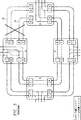
図8は、本発明による、デュアルノードと相互接続されたリングシステムの概略図を示す。
発明の詳細な説明
本発明は、4光ファイバ双方向ラインスイッチ形リング通信システムの方法および装置を提供する。
図1は、現在本技術分野において公知である双方向リング10を示す。それは、双方向トラヒック経路30のリングにより接続された、追加/ドロップマルチプレクサ(ADM)と呼ばれる2つまたはそれ以上のノード(A、B、C、およびDで示す)のセットから成る。ADM20は、トラヒック(電話トラヒックまたは電気通信アプリケーションにおけるデータ)がトラヒック経路内に置かれ(追加され)うる場所であり、そのトラヒックは、リングから抽出される(ドロップされる)もう1つのADM20へ送られる。前記経路は、トラヒックを、(例えば、図1にAで示されている)追加ADMから得、(BおよびCで示されている)任意の中間ADMを経て、それを(Dで示されている)終端ADMにおいてドロップさせるまでの、トラヒックのための道である。この経路は、リング内の別の場所の他点間の他のトラヒックのために再使用されうる。リングを周回する諸経路は、作業グループおよび保護グループの、2つの等しいサイズのグループに分割される。トラヒックは、通常は、作業グループの経路内へのみ挿入され、保護グループは、リング故障の際の使用のためにリザーブされる。トラヒックはまた、保護経路内へも挿入されうるが、そのようなトラヒックは、故障シナリオに際しては保護されない。
双方向リングにおけるトラヒック保護は、個々の経路またはライン(全ての経路を一緒にしたもの)に基づいて行われうる。保護されるべき主要な故障は、一般に、リングのセグメントにおけるブレークであり、これは、そのセグメント上の全ての作業経路が同時に保護されることを必要とする。この理由のために、ここでは保護の基礎としてはラインのみが考慮され、このようなリングは、双方向ラインスイッチ形リング(BLSR)と呼ばれる。リングの物理的アーキテクチャに依存して、この保護のためには2つの可能な機構が利用可能である。もしブレークが、そのセグメント内の保護経路がなお機能的であるようなものであれば(これは一般に、作業経路および保護経路が、物理的に異なる媒体によるものであることを意味する)、スパン(span)スイッチングが行われ(図2参照)、その場合、その特定の故障セグメント32上の作業トラヒックは、保護経路34を経て再ルーティングされる。この保護機構は、同時的なスパンスイッチングが、リングの異なるセグメント内において同時に行われうる利点と、ブレークに隣接するADM20(図2の例においては、AおよびDで示されているADM)のみが、保護動作に関わる利点と、を有するが、もし保護経路もまた故障すれば働かなくなる。
ブレークが起こったセグメント上の保護経路34もまた故障した場合は、図3に示されているように、リングスイッチングと呼ばれる第2保護機構が行われうる。リングスイッチングにおいては、ブレークを生じたセグメントに隣接する(再びAおよびDで示されている)ADM20が、ブレークを生じたセグメントを経て進むはずであったトラヒックを、リングを周回する方向と逆に進むそれらの保護経路内へループする。残余のADMは、そのループされた保護経路上のトラヒックを通過させ、よって新しいループを作り上げる。これは、ブレークを生じたセグメントを、リングの残余の周を回る保護経路により置換することによって、リングを効果的に再構成している。リングスイッチングは、スパンスイッチングよりも一般的な保護機構であるが、それは次の2つの欠点を有する:(1)リング内において、一時に1つリングスイッチングのみが行われうる(さもないと、リングは、複数の接続されないサブネットワークへ分割される)、(2)リングスイッチングの実行は、ネットワーク内の全てのADMによる、相互調整された動作を必要とする(より簡単なスパンスイッチングよりも、複雑でかつ潜在的に低速なタスクである)。
BLSRネットワーク10は、一般に2つのタイプに分類される。一般に2ファイバBLSR(2FBLSR)と呼ばれる最も簡単なタイプにおいては、作業経路および保護経路は、単一の伝送媒体を共用する。媒体が共用されるために、2FBLSRネットワークは、リングスイッチングによってのみ保護される。一般に4ファイバBLSR(4FBLSR)と呼ばれる他のタイプにおいては、作業経路および保護経路は、別個の媒体により担持され、スパンスイッチングおよびリングスイッチングの双方がサポートされる。リングの周りの複数の点におけるスパン保護によると、ある障害が残されうることと、そのような障害が、保守活動により生じる状況をしばしば反映する事実と、のために、リングネットワークが地理的に大きい場合は、4FBLSRネットワークの方が一般に好ましいとして選択される。これは、交換機間電気通信アプリケーションの場合である。同期光ネットワーク(SONET)伝送プロトコルを用い、光時分割多重方式により実現された、電気的2FBLSRおよび4FBLSRネットワークの能力は、現在2.5GB/sと10GB/sとの間にある、SONETにおいて利用可能な最高伝送速度へ制限されている。与えられたファイバのセットにおける容量は、波長分割多重化(WDM)により増大させることができ、その場合は、異なる光SONET信号の複数種類の波長が、単一ファイバにおいて組み合わされる。しかし、WDMのアプローチは、ネットワークのそれぞれのノードに現れるそれぞれのリングのためのADMを有する「スタック形」リングのセットを作る。
SONET ADMの複雑性は、これらのADMのそれぞれが、リングネットワーク内のその点において、ADMにより、たとえもしわずかなトラヒックしか追加/ドロップされないか、または全くトラヒックが追加/ドロップされなくても、かなりのコストを要するほどのものである。このコストは、追加/ドロップされるトラヒックの多くが、光フォーマットによりリングADMへもたらされるが、それが、ADMのリング経路トラヒック内へ含められるために、リングの光フォーマットへ変換し返されうる前に、ADMにより電気的フォーマットへ変換されなければならないという事実により、さらに増大する。
本発明は、WDM/ADM複合体(complexes)のそれぞれを、単一の「光ADM」40により置換した光BLSRを提供し、「光ADM」40は、(毎信号単一波長から成る)光追加/ドロップ信号をとり、これらをWDM技術により、選択されたリング経路内へ直接多重化する。このようにして、個々の波長は、光BLSR内の経路となる。次に、これらの「光ADM」40は、単一「ライン」グループとしての、これら現在の光経路の、追加およびドロップのための経路トラヒックのグルーミング(grooming)と、リング保護スイッチングおよびスパン保護スイッチングと、の双方を行う。これは、入来する光追加/ドロップ信号を電気的信号へ、また逆に光信号へ、変換する必要を解消するので、また、光スイッチング装置が、複雑な電子装置よりも遥かに安価なので、結果としてかなりのコスト節減となる。さらに、「光ADM」40は、光スイッチによりリングスイッチングおよびスパンスイッチングを行うので、結果として電気的ADMによる解決法よりもかなりのコスト節減となる。
光BLSRの望ましい特性
機能的な光双方向ラインスイッチ形リングを作るためには、いくつかの問題を処理する必要がある。これらには、以下のアイテムが含まれる。
1.光ADMは、ADMの間のスパンのそれぞれにおける「ライン」信号の品質をモニタしえなければならない。このモニタリングは、信号の健全性の真の表示を与えなければならない。例えば、光信号、またはレーザ光の単なる存在のモニタリングは、この信号からなんらかの情報が抽出されうるかどうかを表示しないので不十分である。すなわち、モニタリングは、その信号の、情報を正確に伝える能力の真の測度を与えるべきである。それぞれの光経路は、そのようなモニタリング情報を有するので(例えば、SONET BIP−8は、それぞれの光信号内に組込まれ、その信号のオリジナルソースに関するその信号の品質を記述する)、それらを品質インディケータとして用いることは極めて魅力的である。残念ながらこれは、信号が光ADMの追加/ドロップ入力に到達する前に劣化しうるので不適切であり、この品質の使用は、次に正しくないリングスイッチングおよびスパンスイッチングをもたらし、これが劣化信号の問題である。すなわち、光ADMは、信号品質をモニタしうるのみであってはならず、その品質が、「ライン」伝送そのものの正確なインディケータでなければならず、かつその「ライン」機構の外部の条件により影響されてはならない。
2.リングのファイバにおける問題から保護するようにリングスイッチングおよびスパンスイッチングをサポートするほかに、光ADMは、該ADMへ供給する個々の追加/ドロップ機構の保護をもサポートすべきであり、もしそれらの経路の1つが障害を起こせば、それは顧客のトラヒックが最終宛先へ配信されるように保護されるべきである。(1)において注意したように、この保護は、リングおよびスパンの保護とは無関係でなければならない。
3.光リングスイッチングまたはスパンスイッチングを行うために、光ADMは、必要な信号を、それら自身の間で、スパンスイッチングのためには最小限2つのノード(ADM)において、あるいは、リングスイッチングのためには全てのノードにおいて、通信しえなければならない。諸ADMは同時にスイッチングを行わなければならないので、これは重要である。顧客の期待を満たすためには、必要な制御信号の通信および後のスイッチング動作は、50ないし100ミリ秒のタイムフレーム内において行われるべきである。ADMは通常、他のネットワークまたは通信手段へのアクセスをもたないので、これらの通信は、ADM間の光ファイバを経て行われるべきである。これは、ADM間に高速データチャネルを必要とする。実施例においては、サイト間の1ないし2ミリ秒のメッセージ時間が、スイッチング時間の要求を満たすために必要とされる。
4.動作上の保守の目的のために、光リングは、リングの周りのサイトの品質を遠隔保守ステーションからモニタするための)データと、(問題を解決し、活動を相互調整するために、サイト間音声通信により、個人的保守を提供するための)オーディオチャネルと、の双方から成る保守通信チャネルを提供すべきである。アイテム(3)における信号チャネルとは異なって、このデータチャネルは、遥かに低速(1ないし2秒)でありうるが、サイトにおける障害は、診断および保守を容易にするための数百または数千バイトの情報を発生しうるので、かなりの情報量を収容すべきである。
5.光ADMは、かなりの距離だけ隔離されうる。これらの距離を通過するために、顧客のネットワークは光ADMの間に、しばしば、光増幅器、波長分割マルチプレクサ、およびSONET中継器のような装置を含む。この機器の多くがすでに存在し、光ADMの使用に先立って所定の場所に配置されるので、光ADMは、所定の場所にあるそのような機器を有するネットワーク上において使用可能であることが望ましい。従って、これは、機能(1)、(3)、および(4)を行うための光ADMの使用が、現存の機器とコンパチブルでなければならないことを意味する。すなわち、もし光ADMが、新しい光信号を発生するか、または新しいオーバヘッドを現存のSONET信号内へ追加するとすれば、これらの追加は、現存の機能に対してトランスペアレントでなければならない。
6.BLSR機能をサポートするために、光ADMは、ネットワークが必要とするリングスイッチングおよびスパンスイッチングを物理的に行いえなければならない。それらはまた、信号の追加/ドロップグルーミングおよび通過機能をも行いえなければならない。BLSRプロトコルはまた、光ADMが、ネットワークノードの故障に際しスケルチを行って、トラヒックの誤接続を防止することを要求する。最後に、ADMの物理的設計は、保守が、個々のチャネル(単一の光波長)および成分モジュールに対し、他のトラヒックに影響を与えることなく行われうるようなものでなければならない。
図4から図7までは、前節において確認した諸要求を満たすBLSRシステムを示す。その設計は、N種類の信号波長の搬送を意図しており、Nは少なくとも2である。この設計は、3つの主要部分に分解される。第1部分は、「ライン」信号を、その個々の波長成分により組合わせ/分割する、波長分割多重化/多重分離部分42である。第2部分は、それぞれのファイバ上の1つの波長と、それに伴うSONET標準BLSR ADMとから成る、指令および制御チャネル44であり、これは図6に示されている。第3部分は、図7に示されているような、(N−1)個のスレーブ回路46のセットである。それぞれのスレーブ回路46は、図示されている実施例においては、1つから4つまでのスレーブチャネルを含みうる。
4FBLSRにおいては、波長分割多重化/多重分離部分42は、多重化機能(図4には、出力マルチプレクサとして示されている)の4つのコピーと、多重分離機能(図4には、入力デマルチプレクサおよびフィルタとして示されている)の4つのコピーと、を含む。このマルチプレクサ機能は、他の部分により発生せしめられた別個の入力ファイバ48上の個々の波長を受取り、リング内の別の場所で用いられている光増幅器および中継器とのコンパティビリティのためにもし必要ならば、それらを調整し、それらを単一のファイバ出力信号50に多重化する。対応する多重分離機能は、入来する組合せ信号50を、他の部分へ入る別個の出力ファイバ54上のN種類の個々の波長に分割し、コンパティビリティのためにもし必要ならばそれらを再び調整する。
2FBLSRにおいては、図5に示されているように、光多重化および多重分離機能42の2つのコピーのみが用いられる。この多重化および多重分離機能は、ここでは作業波長および保護波長に分割され、それらの波長の半数は作業帯域幅として割当てられ、残りの半数は保護帯域幅として割当てられる。制御構造は、2FBLSRおよび4FBLSRの双方において同じである。2FBLSRにおいては、作業帯域幅および保護帯域幅が単一ファイバを共用するので、故障は、単一スパン上において作業帯域幅および保護帯域幅の双方に影響を及ぼし、従って、2FBLSRにおいてはスパンスイッチングは不可能である。これらの多重化および多重分離機能42は、現存のシステムに対し十分にコンプライアントである信号を搬送する。システムのこの部分には、特定の要求はなされないが、多重化/多重分離部分における故障は、現存の機器により一般に満足される仮定の通り、1つの個々の波長のみに影響を及ぼすか、または全ての波長に影響を及ぼすものと仮定される。
図7に示されている、指令および制御部分44は、「ライン」モニタリング、シグナリングのスイッチング、および光BLSR ADM40の全体的制御を行う。それはまた、システムのトラヒックの1/Nを、電気的SONET ADMの端局56および高速光ラインを経て搬送する。全体的光ADMの「ライン」モニタリングを行うために、SONET ADMは、それ自身の発生したライン信号を、これらの信号の継承BIP−8ラインパリティのチェックと共に用いる。組合わされたファイバ信号における劣化またはカットは、そのファイバ上の全ての搬送波長に等しく影響を及ぼすものと仮定されうる。従って、「ライン」障害は、SONET ADM40により検出され、その通常の動作の過程において、そのBLSRスイッチングプロトコルおよびハードウェアにより保護される。それが用いるプロトコルは、SONET ADMの高速オーバヘッドチャネルにより搬送される、標準SONETオーバヘッドバイト(SONET用語におけるK1/K2)内に組込まれる。これらの同じオーバヘッドチャネル(SONET用語における、バイトD1ないしD12およびE1/E2)はまた、保守データトラヒックおよび保守音声通信のための、光ADMの保守チャネルを提供する。
SONET ADMのこれらのチャネルおよびシグナリングを用いることにより、この設計は、アイテム(1)、(3)、および(4)の要求を与えるが、アイテム(5)が課する要求は満たす。それはまた、SONET ADM自身により搬送される1組のペイロードに関するアイテム(2)の要求をも与える。
SONET ADMは、実際には、その高速ファイバに対しリングスイッチングまたはスパンスイッチングを行うことにより、それ自身の高速波長信号を直接保護するのみであることに注意すべきである。他の波長信号のそれぞれを搬送し、かつ保護するために、(N−1)個のスレーブ回路46のそれぞれは、それ自身の信号のリングスイッチングまたはスパンスイッチングを行うために必要な光ハードウェアを有するが、これに関しては図7を参照されたい。このハードウェアは、指令および制御部分44においてSONET BLSR ADMにより供給される情報を制御するために用いられる。すなわち、SONET ADM40が、リングスイッチングまたはスパンスイッチングを行う時、またはそれらのスイッチングを解除する時、スレーブ部分は、それら部分の個々の波長のために同等の物理機能を行う。この制御情報および関連するスケルチ情報の供給は、指令および制御のために用いられるSONET ADMに必要な変更である。図7に示されているように、スレーブ部分はまた、光信号を、それらの光信号のそれぞれの波長において追加し、またドロップさせるためのスイッチングをも行う。
本発明において、スレーブチャネル追加/ドロップ機能により故障の保護を行うのに、光ADMにおけるスイッチングは不必要である。代わりに、供給端局システムから作業および保護双方の追加/ドロップ機能が、光ADMにおける個々の波長のように搬送される。もし追加/ドロップ機構内、または光リングにおける信号経路に沿っての単一波長内、に故障が発生すれば、供給端局システムにより行われる通常の保護は、障害を起こしたトラヒックを供給保護波長へ移動させる。これは、光「ライン」保護とは無関係な、必要な追加/ドロップ保護および追加/ドロップ保護の維持の双方を提供することにより、アイテム(2)の要求を満たす利点を有する。
本発明のもう1つの実施例においては、光BLSRネットワークは複数の光BLSRリングを含み、それらの光BLSRリングの少なくとも1つは、上述の図4から図7までに関連して説明した光BLSRリングである。そのようなシステムにおいては、第1BLSRリングと第2BLSRリングとの間でデータを伝送することが望ましい。図8は、そのようなデータ伝送を考慮した実施例を示す。
デュアルノード相互接続形リングシステム60と呼ばれうる図8のシステムは、データが、第1リング62から第2リング64へ、高度の障害保護のもとに伝送されることを可能にする。データは、第1リング上の第1ADM66から第2リング上の第1ADM68へ伝送され、同じデータは、第1リング上の第2ADM70から第2リング上の第2ADM72へも伝送される。データを、2つの別個のノードにおいて転送することにより冗長性が確立されるので、もしリング、または一方のノードに問題を生じても、データのための別の経路が存在することになる。それぞれの入力マルチプレクサには、信号の損失、脱落信号を探索しうるモニタが接続されている。 TECHNICAL FIELD OF THE INVENTION The present invention relates generally to data communications, and more particularly to a method and apparatus for an optical bi-directional line-switched ring data communication system.
Background of the invention Bidirectional rings are used in data communication systems to provide high speed data communication with several safeguards that ensure fault tolerance. Optical networks that use bi-directional rings are used in such data communication systems, but the conversion of signals to the proper format required by most optical ring systems is a prior art that involves a large amount of overhead. Another problem with optical bi-directional networks relates to the routing of data when a failure occurs in the system. When multi-channel data is sent over an optical medium, it is difficult and expensive to individually control the routing of those channels when a failure occurs. This is because in prior art systems each channel has its own fault detection and rerouting circuitry.
For these reasons, control the routing of signals in the network, taking into account the simple and efficient provision of fault detection in the medium, adding traffic to and dropping traffic from the medium. There is also a need for an optical bi-directional ring communication system with a maintenance channel that is compatible with devices currently in use.
SUMMARY OF THE INVENTION The present invention is intended to enable switching in the event of a path or system failure that substantially eliminates or reduces disadvantages and problems associated with previously developed protection systems and methods. An optical add / drop multiplexer for use in a telecommunications system is provided.
More specifically, the present invention provides an optical add / drop multiplexer for use in, for example, a multiple fiber optic bi-directional line switched ring capable of carrying signals of N wavelengths. Each optical ADM node may include multiple input demultiplexer / output multiplexer portions, command and control channels with multiple fibers, and up to N-1 slave circuits. Each multi-input demultiplexer / output multiplexer section includes an input demultiplexer that receives and demultiplexes signals from the fiber, and an output multiplexer that receives demultiplexed wavelengths from the inside and multiplexes them into an output signal. Have. The command and control channel can be a standard bi-directional line switch with one channel coupled to each fiber of the system. Each slave circuit including a plurality of optical switching circuits is coupled to the multi-input demultiplexer / output multiplexer section so that the optical switching circuits can operate to carry traffic of up to N wavelengths. A command and control channel associated with a SONET bi-directional line switched ring monitors multiple lines in the bi-directional line switched ring and optical add / drop multiplexers in response to detected signals on the multiple lines To control the operation. If traffic disruption occurs, the command and control channel will indicate so and reroute and protect the traffic using its dependent optical switching circuitry.
The present invention is equally applicable to two-fiber bi-directional line switch ring rings and four-fiber bi-directional line switch rings.
In addition to the bidirectional line switch ring, the present invention can be applied to other optical communication systems.
[Brief description of the drawings]
A more complete understanding and further features and advantages of the present invention can be obtained by reference to the following description taken in conjunction with the accompanying drawings. In the drawing
FIG. 1 shows a prior art bidirectional ring communication system,
FIG. 2 shows a prior art bi-directional ring communication system with span switching,
FIG. 3 illustrates a prior art bidirectional ring communication system that performs ring switching,
FIG. 4 shows a schematic diagram of an add / drop multiplexer (ADM) for a four fiber optic bi-directional line switched ring communication system according to the present invention;
FIG. 5 shows a schematic diagram of an add / drop multiplexer (ADM) for a two fiber optic bi-directional line switched ring communication system according to the present invention;
FIG. 6 shows a schematic diagram of an electrical ADM used for control of a four fiber optic bi-directional line switched ring communication system according to the present invention;
FIG. 7 shows a schematic diagram of an optical slave circuit for control of a four-fiber bi-directional line-switched ring communication system according to the present invention,
FIG. 8 shows a schematic diagram of a ring system interconnected with dual nodes according to the present invention.
DETAILED DESCRIPTION OF THE INVENTION The present invention provides a method and apparatus for a four fiber optic bi-directional line switch ring communication system.
FIG. 1 shows a
Traffic protection in a bi-directional ring can be based on individual paths or lines (all paths together). The main failure to be protected is generally a break in a segment of the ring, which requires that all work paths on that segment be protected simultaneously. For this reason, only lines are considered here as the basis for protection, and such rings are called bidirectional line switched rings (BLSR). Depending on the physical architecture of the ring, two possible mechanisms are available for this protection. If the break is such that the protection path within the segment is still functional (this generally means that the work path and protection path are from physically different media), span (Span) switching occurs (see FIG. 2), in which case the work traffic on that particular failed
If the
The BLSR
The complexity of SONET ADMs is significant for each of these ADMs, even if little or no traffic is added / dropped by the ADM at that point in the ring network. Is costly. This cost comes before much of the added / dropped traffic is brought into the ring ADM by the optical format, but can be converted back to the ring optical format for inclusion in the ring path traffic of the ADM. Further, this is further increased by the fact that it must be converted to an electrical format by ADM.
The present invention provides an optical BLSR in which each of the WDM / ADM complexes is replaced by a single “optical ADM” 40, which is an optical (consisting of a single wavelength per signal). Add / drop signals are taken and multiplexed directly into the selected ring path by WDM technology. In this way, each wavelength becomes a path in the light BLSR. These “optical ADMs” 40 then group the route traffic for adding and dropping these current optical paths as a single “line” group, and ring protection switching and span protection switching. And both. This eliminates the need to convert incoming optical add / drop signals to electrical signals and vice versa, and because optical switching devices are much cheaper than complex electronic devices, The result is considerable cost savings. Furthermore, the “optical ADM” 40 performs ring switching and span switching with an optical switch, resulting in significant cost savings over the electrical ADM solution.
Desirable characteristics of optical BLSR In order to create a functional optical bi-directional line-switched ring, several problems need to be addressed. These include the following items:
1. The optical ADM must be able to monitor the quality of the “line” signal in each of the spans between ADMs. This monitoring must provide a true indication of signal health. For example, monitoring the mere presence of an optical signal, or laser light, is insufficient because it does not indicate whether any information can be extracted from this signal. That is, monitoring should give a true measure of the signal's ability to accurately convey information. Since each optical path has such monitoring information (eg SONET BIP-8 is embedded in each optical signal and describes the quality of that signal with respect to the original source of that signal) It is very attractive to use as an indicator. Unfortunately this is inadequate because the signal can degrade before reaching the add / drop input of the optical ADM, and the use of this quality then leads to incorrect ring and span switching, which is It is a problem. That is, the optical ADM must not only be able to monitor the signal quality, but the quality must be an accurate indicator of the “line” transmission itself, and depending on conditions outside the “line” mechanism. Must not be affected.
2. In addition to supporting ring switching and span switching to protect against problems in the fiber of the ring, the optical ADM should also support protection of the individual add / drop mechanisms that feed the ADM, if their path If one of them fails, it should be protected so that customer traffic is delivered to the final destination. As noted in (1), this protection must be independent of ring and span protection.
3. In order to perform optical ring switching or span switching, the optical ADM can send the necessary signals between itself, at least two nodes (ADM) for span switching, or for ring switching. All nodes must be able to communicate. This is important because ADMs must switch simultaneously. In order to meet customer expectations, the necessary control signal communication and subsequent switching operations should be performed within a time frame of 50 to 100 milliseconds. Since ADMs typically do not have access to other networks or communication means, these communications should take place over optical fibers between the ADMs. This requires a high speed data channel between ADMs. In an embodiment, a 1 to 2 millisecond message time between sites is required to meet the switching time requirement.
4). For operational maintenance purposes, the optical ring is inter-site to solve problems and to coordinate activities (to monitor the quality of the site around the ring from a remote maintenance station) A maintenance communication channel consisting of both an audio channel (to provide personal maintenance via voice communication) should be provided. Unlike the signal channel in item (3), this data channel can be much slower (1 to 2 seconds), but failures at the site can be hundreds or thousands to facilitate diagnosis and maintenance. Since a byte of information can be generated, a considerable amount of information should be accommodated.
5. The optical ADM can be isolated by a considerable distance. To pass these distances, customer networks often include devices such as optical amplifiers, wavelength division multiplexers, and SONET repeaters during the optical ADM. Since many of these devices already exist and are placed in place prior to the use of the optical ADM, it is desirable that the optical ADM be usable on a network having such devices in place. . This therefore means that the use of the optical ADM to perform functions (1), (3) and (4) must be compatible with existing equipment. That is, if the optical ADM generates new optical signals or adds new overhead into the existing SONET signal, these additions must be transparent to the existing function.
6). In order to support the BLSR function, the optical ADM must be able to physically perform the ring and span switching required by the network. They must also be able to perform signal add / drop grooming and passing functions. The BLSR protocol also requires that optical ADMs squelch upon network node failure to prevent traffic misconnections. Finally, the physical design of the ADM must be such that maintenance can be performed on individual channels (single optical wavelength) and component modules without affecting other traffic.
4 to 7 show a BLSR system that satisfies the requirements identified in the previous section. The design is intended to carry N signal wavelengths, where N is at least 2. This design is broken down into three main parts. The first part is a wavelength division multiplexing / demultiplexing
In 4FBLSR, the wavelength division multiplexing / demultiplexing
In 2FBLSR, only two copies of the optical multiplexing and
The command and
By using these channels and signaling of SONET ADM, this design gives the requirements of items (1), (3), and (4), but satisfies the requirements imposed by item (5). It also gives a request for item (2) for a set of payloads carried by the SONET ADM itself.
It should be noted that a SONET ADM actually only protects its own high speed wavelength signal directly by ring switching or span switching for its high speed fiber. In order to carry and protect each of the other wavelength signals, each of the (N-1)
In the present invention, the switching in the optical ADM is unnecessary to protect the failure by the slave channel addition / drop function. Instead, both work and protection add / drop functions from the serving terminal system are carried like individual wavelengths in the optical ADM. If a failure occurs within the add / drop mechanism or within a single wavelength along the signal path in the optical ring, the normal protection provided by the serving terminal system is to provide the failed traffic to the serving protection wavelength. Move to. This has the advantage of meeting the requirements of item (2) by providing both the necessary add / drop protection and maintaining the add / drop protection, independent of optical “line” protection.
In another embodiment of the present invention, the optical BLSR network includes a plurality of optical BLSR rings, at least one of which is the optical BLSR described in connection with FIGS. 4-7 above. It is a ring. In such a system, it is desirable to transmit data between the first BLSR ring and the second BLSR ring. FIG. 8 shows an embodiment considering such data transmission.
The system of FIG. 8, which may be referred to as a dual node interconnected ring system 60, allows data to be transmitted from the
Claims (37)
多重入力デマルチプレクサ/出力マルチプレクサ部分であって、それぞれの部分が、前記多重ファイバの1つに結合した入力デマルチプレクサおよび出力マルチプレクサを含む、前記多重入力デマルチプレクサ/出力マルチプレクサ部分と、
多重ファイバを有する指令および制御チャネルであって、それぞれの指令および制御チャネルファイバが、前記入力デマルチプレクサ/出力マルチプレクサ部分の1つに結合している、前記指令および制御チャネルと、
前記多重入力デマルチプレクサ/出力マルチプレクサ部分に結合した複数の光スイッチング回路を含むN−1個までのスレーブ回路であって、前記光スイッチング回路がN種類までの波長のトラヒックを搬送する動作を行いうるようにしている、前記スレーブ回路と、を含み、
前記指令および制御チャネルが、前記複数のファイバ上の信号をモニタし、該複数のファイバ上において検出された信号に応答して前記N−1個のスレーブ回路の動作を制御する、
前記多重光ファイバ双方向ラインスイッチ形リング。Multiple fiber optic bi-directional line switched ring capable of carrying N wavelengths of signals, including a plurality of optical add / drop multiplexer nodes, each optical add / drop multiplexer node comprising:
A multiple-input demultiplexer / output multiplexer portion, each portion including an input demultiplexer / output multiplexer coupled to one of the multiple fibers;
A command and control channel having multiple fibers, each command and control channel fiber coupled to one of the input demultiplexer / output multiplexer portions;
Up to N-1 slave circuits including a plurality of optical switching circuits coupled to the multi-input demultiplexer / output multiplexer portion, wherein the optical switching circuit can operate to carry traffic of up to N wavelengths. And including the slave circuit,
The command and control channel monitors signals on the plurality of fibers and controls the operation of the N-1 slave circuits in response to signals detected on the plurality of fibers;
The multiple optical fiber bidirectional line switch type ring.
前記第1多重光ファイバ双方向ラインスイッチ形リングを、前記第2多重光ファイバ双方向ラインスイッチ形リングに結合させるドロップおよび継続部分であって、該ドロップおよび継続部分が、前記第1リング上の第1追加/ドロップマルチプレクサからのデータを、前記第2リング上の第1追加/ドロップマルチプレクサへ伝送する、前記ドロップおよび継続部分と、
をさらに含む、請求項1に記載のシステム。A second multiple optical fiber bidirectional line switch ring;
A drop and continuation portion coupling the first multiplex fiber optic bi-directional line switch ring to the second multiplex fiber optic bi-directional line switch ring, the drop and continuation portion on the first ring The drop and continuation portion for transmitting data from a first add / drop multiplexer to a first add / drop multiplexer on the second ring;
The system of claim 1, further comprising:
多重入力デマルチプレクサ/出力マルチプレクサ部分であって、それぞれの部分が、前記ファイバの1つに結合した入力デマルチプレクサおよび出力マルチプレクサを含む、前記多重入力デマルチプレクサ/出力マルチプレクサ部分と、
複数のファイバを有する指令および制御チャネルであって、それぞれの指令および制御チャネルファイバが、前記入力デマルチプレクサまたは出力マルチプレクサ部分の1つに結合している、前記指令および制御チャネルと、
N−1個までのスレーブ回路のそれぞれのスレーブ回路が、前記多重入力デマルチプレクサ/出力マルチプレクサ部分の少なくとも1つに結合した複数の光スイッチング回路を含むことにより、該光スイッチング回路がN種類までの波長のトラヒックを搬送する動作を行いうる、前記スレーブ回路と、を含み、
前記指令および制御チャネルが、前記複数のファイバ上の信号をモニタし、該複数のファイバ上において検出された信号に応答して前記N−1個のスレーブ回路の動作を制御する、
前記光追加/ドロップマルチプレクサ。In an optical add / drop multiplexer used in a bidirectional line-switched ring capable of carrying optical signals of N wavelengths,
A multi-input demultiplexer / output multiplexer portion, each portion including an input demultiplexer / output multiplexer coupled to one of the fibers;
A command and control channel having a plurality of fibers, each of the command and control channel fibers, bonded to one of said input demultiplexer and output multiplexer portion, and the command and control channel,
Each slave circuit of up to N-1 slave circuits includes a plurality of optical switching circuits coupled to at least one of the multiple-input demultiplexer / output multiplexer portions , so that the optical switching circuit can have up to N types The slave circuit capable of performing an operation of carrying wavelength traffic, and
The command and control channel monitors signals on the plurality of fibers and controls the operation of the N-1 slave circuits in response to signals detected on the plurality of fibers;
The optical add / drop multiplexer.
前記入力デマルチプレクサのそれぞれにおいて信号を受取るステップと、
該信号をN種類の波長へ分離するステップと、
1つの波長を前記指令および制御チャネルへ送るステップと、
残余のN−1種類の波長をN−1個のスレーブ回路へ送るステップと、
前記指令および制御チャネル波長信号を信号品質に関しモニタリングするステップと、
前記指令および制御チャネル波長信号の信号品質に応答して、前記N−1個のスレーブ回路の動作を制御するステップと、
を含む、前記方法。In a method for protecting traffic traveling in a multi-fiber bi-directional line switch ring capable of carrying signals of N types of wavelengths, the multi-fiber bi-directional line switch ring comprises a plurality of optical add / drop multiplexer nodes Each optical add / drop multiplexer node is a multiple input demultiplexer / output multiplexer portion, each portion including an input demultiplexer and an output multiplexer coupled to one of the multiple fibers. An input demultiplexer / output multiplexer portion and command and control channels having multiple fibers, each command and control channel fiber being coupled to one of the input demultiplexer / output multiplexer portions and control Each of the channel and up to N-1 slave circuits includes a plurality of optical switching circuits coupled to the multiple input demultiplexer / output multiplexer portion, the optical switching circuit having traffic of up to N wavelengths. The slave circuit, wherein the method comprises:
Receiving a signal at each of the input demultiplexers;
Separating the signal into N wavelengths;
Sending one wavelength to the command and control channel;
Sending the remaining N-1 types of wavelengths to N-1 slave circuits;
Monitoring the command and control channel wavelength signals for signal quality;
Controlling the operation of the N-1 slave circuits in response to the signal quality of the command and control channel wavelength signals ;
Said method.
をさらに含む、請求項29に記載の方法。Initiating switching to switch traffic from a first path to a second path in the system when a fault is detected in the command and control channel signals;
30. The method of claim 29, further comprising:
前記N−1個のスレーブ回路のそれぞれにおける前記スレーブチャネルの少なくとも1つにより、前記N−1個のスレーブ回路のそれぞれに対する保護を行うステップ、
をさらに含む、請求項29に記載の方法。Each of the N-1 slave circuits further includes up to four slave channels, the method comprising:
Protecting each of the N-1 slave circuits with at least one of the slave channels in each of the N-1 slave circuits;
30. The method of claim 29, further comprising:
前記第1多重光ファイバ双方向ラインスイッチ形リングと、前記第2多重光ファイバ双方向ラインスイッチ形リングとの間に、ドロップおよび継続部分を結合させるステップと、
前記第1リング上の第1追加/ドロップマルチプレクサから、前記第2リング上の第1追加/ドロップマルチプレクサへ、前記ドロップおよび継続部分を経てデータを伝送するステップと、
をさらに含む、請求項29に記載の方法。Coupling a second multiplex fiber bi-directional line switch ring to the first multiplex fiber bi-directional line switch ring;
Coupling a drop and a continuation portion between the first multiple fiber optic bidirectional line switch ring and the second multiple fiber optic bidirectional line switch ring;
Transmitting data via the drop and continuation portion from a first add / drop multiplexer on the first ring to a first add / drop multiplexer on the second ring;
30. The method of claim 29, further comprising:
をさらに含む、請求項35に記載の方法。Transmitting data via the drop and continuation portion from a second add / drop multiplexer on the first ring to a second add / drop multiplexer on the second ring;
36. The method of claim 35, further comprising:
Applications Claiming Priority (3)
| Application Number | Priority Date | Filing Date | Title |
|---|---|---|---|
| US4332297P | 1997-04-15 | 1997-04-15 | |
| US60/043,322 | 1997-04-15 | ||
| PCT/US1998/007539 WO1998047255A1 (en) | 1997-04-15 | 1998-04-14 | Method and apparatus for an optical bi-directional line switched ring data communications system |
Publications (2)
| Publication Number | Publication Date |
|---|---|
| JP2001520830A JP2001520830A (en) | 2001-10-30 |
| JP4070246B2 true JP4070246B2 (en) | 2008-04-02 |
Family
ID=21926575
Family Applications (1)
| Application Number | Title | Priority Date | Filing Date |
|---|---|---|---|
| JP54423898A Expired - Lifetime JP4070246B2 (en) | 1997-04-15 | 1998-04-14 | Method and apparatus for optical bidirectional line switch type ring data communication system |
Country Status (7)
| Country | Link |
|---|---|
| US (1) | US6163527A (en) |
| EP (1) | EP0976215B1 (en) |
| JP (1) | JP4070246B2 (en) |
| AT (1) | ATE433234T1 (en) |
| CA (1) | CA2286593A1 (en) |
| DE (1) | DE69840867D1 (en) |
| WO (1) | WO1998047255A1 (en) |
Families Citing this family (56)
| Publication number | Priority date | Publication date | Assignee | Title |
|---|---|---|---|---|
| US6657952B1 (en) | 1997-11-28 | 2003-12-02 | Nec Corporation | Ring network for sharing protection resource by working communication paths |
| JPH11239100A (en) * | 1998-02-20 | 1999-08-31 | Fujitsu Ltd | Light wavelength multiple system having redundant system |
| EP1748617A3 (en) * | 1998-09-11 | 2011-02-09 | Hitachi, Ltd. | IP packet communication apparatus |
| JP3531526B2 (en) * | 1999-05-13 | 2004-05-31 | 日本電気株式会社 | Communications system |
| JP3586586B2 (en) * | 1999-05-24 | 2004-11-10 | 日本電気株式会社 | Light wave ring system |
| US6381643B1 (en) * | 1999-11-08 | 2002-04-30 | International Business Machines Corporation | Mechanism and procedure for detecting switch mis-cabling |
| JP3584965B2 (en) * | 1999-12-09 | 2004-11-04 | 日本電気株式会社 | Optical line protection method |
| WO2001067136A2 (en) * | 2000-03-03 | 2001-09-13 | Corning, Inc. | A ring interconnection architecture |
| US6922530B1 (en) * | 2000-04-06 | 2005-07-26 | Fujitsu Limited | Method and apparatus for optical channel switching in an optical add/drop multiplexer |
| US6795394B1 (en) * | 2000-04-26 | 2004-09-21 | Nortel Networks Limited | Data network having enhanced availability of extra traffic |
| FR2809905B1 (en) * | 2000-05-30 | 2002-08-30 | Cit Alcatel | TRANSFER METHOD WITH SIGNAL PROCESSING BETWEEN TWO SEPARATE TRANSMIT / RECEIVE INTERFACES |
| JP2001352342A (en) * | 2000-06-07 | 2001-12-21 | Fujitsu Ltd | Network management method and network node unit, and mesh type network |
| US6865148B1 (en) * | 2000-09-15 | 2005-03-08 | Ciena Corporation | Method for routing network switching information |
| JP4592170B2 (en) * | 2000-10-18 | 2010-12-01 | 株式会社東芝 | Optical transmission equipment |
| US7016300B2 (en) * | 2000-12-30 | 2006-03-21 | Redback Networks Inc. | Protection mechanism for an optical ring |
| US7209436B1 (en) * | 2000-12-30 | 2007-04-24 | Redback Networks Inc. | Method and apparatus for variable rate pipes |
| GB2386274B (en) * | 2000-12-30 | 2004-07-14 | Redback Networks Inc | Non-BLSR protected layer 2/3 channel provisioning |
| US6975589B2 (en) * | 2000-12-30 | 2005-12-13 | Redback Networks Inc. | Method and apparatus for a hybrid variable rate pipe |
| US6577412B2 (en) | 2001-02-02 | 2003-06-10 | Fujitsu Network Communications, Inc. | System and method of determining end point candidates for an optical channel in a data network |
| US7110364B1 (en) | 2001-04-19 | 2006-09-19 | Fujitsu Limited | Optical link adjacency discovery protocol and an optical network therefor |
| US6307986B1 (en) | 2001-04-24 | 2001-10-23 | Seneca Networks | Protection switching in bidirectional WDM optical communication networks with transponders |
| US6321004B1 (en) | 2001-04-24 | 2001-11-20 | Seneca Networks | Protection switching in bidirectional WDM optical communication networks |
| US7272307B2 (en) * | 2001-05-25 | 2007-09-18 | Tellabs Operations, Inc. | Virtual protection channel for fiber optic ring network |
| US7643492B2 (en) | 2001-05-30 | 2010-01-05 | Fujitsu Limited | Network bandwidth reservation method |
| US6594234B1 (en) | 2001-05-31 | 2003-07-15 | Fujitsu Network Communications, Inc. | System and method for scheduling traffic for different classes of service |
| US8228797B1 (en) | 2001-05-31 | 2012-07-24 | Fujitsu Limited | System and method for providing optimum bandwidth utilization |
| US8385342B2 (en) | 2001-05-31 | 2013-02-26 | Fujitsu Limited | System and method of virtual private network route target filtering |
| US20020184388A1 (en) * | 2001-06-01 | 2002-12-05 | Nimer Yaseen | Layered approach to virtual private routing |
| US7450505B2 (en) * | 2001-06-01 | 2008-11-11 | Fujitsu Limited | System and method for topology constrained routing policy provisioning |
| US8014283B2 (en) * | 2001-06-01 | 2011-09-06 | Fujitsu Limited | System and method for topology constrained QoS provisioning |
| US7450578B2 (en) * | 2001-06-01 | 2008-11-11 | Fujitsu Limited | Method of addressing and routing data |
| US7912074B2 (en) * | 2001-06-01 | 2011-03-22 | Fujitsu Limited | System and method of multiplexing data from multiple ports |
| US7756957B2 (en) | 2001-06-01 | 2010-07-13 | Fujitsu Limited | End-to-end governed data transfers in a network |
| US7289429B2 (en) * | 2001-06-01 | 2007-10-30 | Fujitsu Network Communications, Inc. | System and method to perform non-service effecting bandwidth reservation using a reservation signaling protocol |
| US7245635B2 (en) * | 2001-06-01 | 2007-07-17 | Fujitsu Limited | System and method for resizing the physical link bandwidth based on utilization thereof |
| US6834056B2 (en) * | 2001-06-26 | 2004-12-21 | Occam Networks | Virtual local area network protection switching |
| US20030005165A1 (en) * | 2001-06-28 | 2003-01-02 | Dave Langridge | Protection switching in ring-configured networks |
| US6766482B1 (en) | 2001-10-31 | 2004-07-20 | Extreme Networks | Ethernet automatic protection switching |
| WO2003067843A1 (en) * | 2002-02-06 | 2003-08-14 | Wuhan Fiberhome Networks Co., Ltd | Resilient multiple service ring |
| US7116905B2 (en) | 2002-03-27 | 2006-10-03 | Fujitsu Limited | Method and system for control signaling in an open ring optical network |
| US7231148B2 (en) * | 2002-03-28 | 2007-06-12 | Fujitsu Limited | Flexible open ring optical network and method |
| US7206281B2 (en) * | 2002-05-03 | 2007-04-17 | Ciena Corporation | Calculating physical routes in a communication network |
| US8463947B2 (en) * | 2002-08-28 | 2013-06-11 | Tellabs Operations, Inc. | Method of finding rings for optimal routing of digital information |
| US7346709B2 (en) * | 2002-08-28 | 2008-03-18 | Tellabs Operations, Inc. | Methods for assigning rings in a network |
| US20040052530A1 (en) * | 2002-09-17 | 2004-03-18 | Cechan Tian | Optical network with distributed sub-band rejections |
| CN100490415C (en) * | 2002-11-06 | 2009-05-20 | 武汉烽火网络有限责任公司 | Multi-service ring of N-subring structure based on multiple FE, GE and 10GE |
| US7421197B2 (en) * | 2003-01-21 | 2008-09-02 | Fujitsu Limited | Optical network protection switching architecture |
| US7509438B1 (en) | 2003-02-14 | 2009-03-24 | Cisco Technology, Inc. | Bi-directional line switched ring support for path trace monitoring on a protection path |
| US7483636B2 (en) * | 2003-07-28 | 2009-01-27 | Fujitsu Limited | Optical network with sub-band rejection and bypass |
| US7023793B2 (en) * | 2003-08-01 | 2006-04-04 | Ciena Corporation | Resiliency of control channels in a communications network |
| JP4001093B2 (en) * | 2003-09-18 | 2007-10-31 | オムロン株式会社 | Programmable controller and redundant network system |
| US20050095001A1 (en) * | 2003-10-29 | 2005-05-05 | Fujitsu Limited | Method and system for increasing network capacity in an optical network |
| US7450851B2 (en) * | 2004-08-27 | 2008-11-11 | Fujitsu Limited | System and method for modularly scalable architecture for optical networks |
| CN101321031B (en) * | 2008-07-16 | 2011-12-07 | 中兴通讯股份有限公司 | Sharing protection method and system for wavelength division multiplexing looped network |
| DE102009023485A1 (en) * | 2009-06-02 | 2010-12-09 | T-Mobile International Ag | Method for transmitting real-time data packets in converged networks |
| CN102142975B (en) * | 2010-02-01 | 2015-05-13 | 中兴通讯股份有限公司 | Method and system for service protection based on dual node interconnection protection structure in transmission network |
Family Cites Families (5)
| Publication number | Priority date | Publication date | Assignee | Title |
|---|---|---|---|---|
| DE59310326D1 (en) * | 1993-10-29 | 2003-02-27 | Siemens Ag | Optical, transparent ring network with equivalent switching paths |
| JPH0818592A (en) * | 1994-06-30 | 1996-01-19 | Fujitsu Ltd | Optical fiber transmission system having ring protection by optical switching |
| IT1277204B1 (en) * | 1995-10-19 | 1997-11-05 | Pirelli S P A Ora Pirelli Cavi | TRANSPARENT OPTICAL COMMUNICATION NETWORK WITH SELF-PROTECTED RING |
| JP3640721B2 (en) * | 1996-02-05 | 2005-04-20 | 富士通株式会社 | Ring transmission system transition method and transmission apparatus |
| US5751454A (en) * | 1996-10-10 | 1998-05-12 | Northern Telecom Limited | Wavelength bypassed ring networks |
-
1998
- 1998-04-14 CA CA002286593A patent/CA2286593A1/en not_active Abandoned
- 1998-04-14 JP JP54423898A patent/JP4070246B2/en not_active Expired - Lifetime
- 1998-04-14 US US09/059,919 patent/US6163527A/en not_active Expired - Lifetime
- 1998-04-14 AT AT98918217T patent/ATE433234T1/en not_active IP Right Cessation
- 1998-04-14 EP EP98918217A patent/EP0976215B1/en not_active Expired - Lifetime
- 1998-04-14 WO PCT/US1998/007539 patent/WO1998047255A1/en active Application Filing
- 1998-04-14 DE DE69840867T patent/DE69840867D1/en not_active Expired - Lifetime
Also Published As
| Publication number | Publication date |
|---|---|
| JP2001520830A (en) | 2001-10-30 |
| DE69840867D1 (en) | 2009-07-16 |
| US6163527A (en) | 2000-12-19 |
| CA2286593A1 (en) | 1998-10-22 |
| ATE433234T1 (en) | 2009-06-15 |
| EP0976215B1 (en) | 2009-06-03 |
| EP0976215A1 (en) | 2000-02-02 |
| WO1998047255A1 (en) | 1998-10-22 |
Similar Documents
| Publication | Publication Date | Title |
|---|---|---|
| JP4070246B2 (en) | Method and apparatus for optical bidirectional line switch type ring data communication system | |
| JP3008260B2 (en) | Ring network communication structure of optical transmission line and reconfigurable node for that structure | |
| EP0848873B1 (en) | Optical communication system | |
| US6701085B1 (en) | Method and apparatus for data transmission in the wavelength-division multiplex method in an optical ring network | |
| US6046833A (en) | Method and apparatus for operation, protection, and restoration of heterogeneous optical communication networks | |
| US7352966B2 (en) | Method and apparatus for capacity-efficient restoration in an optical communication system | |
| US7072580B2 (en) | Autoprotected optical communication ring network | |
| US6567194B1 (en) | Optical communication network and protection methods | |
| US5986783A (en) | Method and apparatus for operation, protection, and restoration of heterogeneous optical communication networks | |
| US6579018B1 (en) | Four-fiber ring optical cross connect system using 4×4 switch matrices | |
| EP1031198A1 (en) | Telecommunications network having shared protect capacity architecture | |
| US6973267B1 (en) | Autoprotected optical communication ring network | |
| EP0949777A2 (en) | Path switched shared protection | |
| JP3586586B2 (en) | Light wave ring system | |
| US20060045519A1 (en) | Dual homing for DWDM networks in fiber rings | |
| JP4676657B2 (en) | Optical add / drop multiplexer | |
| EP0931392B1 (en) | Apparatus and method for restoring fiber optic communications network connections | |
| US6735390B1 (en) | Method and apparatus for terminating optical links in an optical network | |
| EP1075105B1 (en) | Autoprotected optical communication ring network | |
| EP1065822A1 (en) | Autoprotected optical communication ring network | |
| JP2002540700A (en) | Fault protection in networks | |
| JPH11112422A (en) | Multi-wavelength network switching device and multi-wavelength optical ring network system | |
| WO2002035749A2 (en) | Optical communications network and node for forming such a network | |
| JPH10336225A (en) | User channel signal protection system | |
| IL148391A (en) | Switching assembly for protected optical path |
Legal Events
| Date | Code | Title | Description |
|---|---|---|---|
| A621 | Written request for application examination |
Free format text: JAPANESE INTERMEDIATE CODE: A621 Effective date: 20050413 |
|
| A131 | Notification of reasons for refusal |
Free format text: JAPANESE INTERMEDIATE CODE: A131 Effective date: 20070522 |
|
| A601 | Written request for extension of time |
Free format text: JAPANESE INTERMEDIATE CODE: A601 Effective date: 20070731 |
|
| A602 | Written permission of extension of time |
Free format text: JAPANESE INTERMEDIATE CODE: A602 Effective date: 20070910 |
|
| A521 | Request for written amendment filed |
Free format text: JAPANESE INTERMEDIATE CODE: A523 Effective date: 20070925 |
|
| TRDD | Decision of grant or rejection written | ||
| A01 | Written decision to grant a patent or to grant a registration (utility model) |
Free format text: JAPANESE INTERMEDIATE CODE: A01 Effective date: 20071218 |
|
| A61 | First payment of annual fees (during grant procedure) |
Free format text: JAPANESE INTERMEDIATE CODE: A61 Effective date: 20080115 |
|
| R150 | Certificate of patent or registration of utility model |
Free format text: JAPANESE INTERMEDIATE CODE: R150 |
|
| FPAY | Renewal fee payment (event date is renewal date of database) |
Free format text: PAYMENT UNTIL: 20110125 Year of fee payment: 3 |
|
| FPAY | Renewal fee payment (event date is renewal date of database) |
Free format text: PAYMENT UNTIL: 20110125 Year of fee payment: 3 |
|
| FPAY | Renewal fee payment (event date is renewal date of database) |
Free format text: PAYMENT UNTIL: 20120125 Year of fee payment: 4 |
|
| FPAY | Renewal fee payment (event date is renewal date of database) |
Free format text: PAYMENT UNTIL: 20120125 Year of fee payment: 4 |
|
| FPAY | Renewal fee payment (event date is renewal date of database) |
Free format text: PAYMENT UNTIL: 20130125 Year of fee payment: 5 |
|
| FPAY | Renewal fee payment (event date is renewal date of database) |
Free format text: PAYMENT UNTIL: 20140125 Year of fee payment: 6 |
|
| R250 | Receipt of annual fees |
Free format text: JAPANESE INTERMEDIATE CODE: R250 |
|
| R250 | Receipt of annual fees |
Free format text: JAPANESE INTERMEDIATE CODE: R250 |
|
| R250 | Receipt of annual fees |
Free format text: JAPANESE INTERMEDIATE CODE: R250 |
|
| R250 | Receipt of annual fees |
Free format text: JAPANESE INTERMEDIATE CODE: R250 |
|
| R250 | Receipt of annual fees |
Free format text: JAPANESE INTERMEDIATE CODE: R250 |
|
| EXPY | Cancellation because of completion of term |