EP1162114A2 - 'An external rear-view mirror for a motor vehicle' - Google Patents
'An external rear-view mirror for a motor vehicle' Download PDFInfo
- Publication number
- EP1162114A2 EP1162114A2 EP01113383A EP01113383A EP1162114A2 EP 1162114 A2 EP1162114 A2 EP 1162114A2 EP 01113383 A EP01113383 A EP 01113383A EP 01113383 A EP01113383 A EP 01113383A EP 1162114 A2 EP1162114 A2 EP 1162114A2
- Authority
- EP
- European Patent Office
- Prior art keywords
- cavity
- opening
- light
- vehicle
- motor vehicle
- Prior art date
- Legal status (The legal status is an assumption and is not a legal conclusion. Google has not performed a legal analysis and makes no representation as to the accuracy of the status listed.)
- Withdrawn
Links
- 229910052736 halogen Inorganic materials 0.000 claims description 2
- 150000002367 halogens Chemical class 0.000 claims description 2
- 230000000452 restraining effect Effects 0.000 claims 2
- 239000004020 conductor Substances 0.000 description 1
- 230000001419 dependent effect Effects 0.000 description 1
Images

Classifications
-
- B—PERFORMING OPERATIONS; TRANSPORTING
- B60—VEHICLES IN GENERAL
- B60Q—ARRANGEMENT OF SIGNALLING OR LIGHTING DEVICES, THE MOUNTING OR SUPPORTING THEREOF OR CIRCUITS THEREFOR, FOR VEHICLES IN GENERAL
- B60Q1/00—Arrangement of optical signalling or lighting devices, the mounting or supporting thereof or circuits therefor
- B60Q1/02—Arrangement of optical signalling or lighting devices, the mounting or supporting thereof or circuits therefor the devices being primarily intended to illuminate the way ahead or to illuminate other areas of way or environments
- B60Q1/24—Arrangement of optical signalling or lighting devices, the mounting or supporting thereof or circuits therefor the devices being primarily intended to illuminate the way ahead or to illuminate other areas of way or environments for lighting other areas than only the way ahead
- B60Q1/247—Arrangement of optical signalling or lighting devices, the mounting or supporting thereof or circuits therefor the devices being primarily intended to illuminate the way ahead or to illuminate other areas of way or environments for lighting other areas than only the way ahead for illuminating the close surroundings of the vehicle, e.g. to facilitate entry or exit
-
- B—PERFORMING OPERATIONS; TRANSPORTING
- B60—VEHICLES IN GENERAL
- B60Q—ARRANGEMENT OF SIGNALLING OR LIGHTING DEVICES, THE MOUNTING OR SUPPORTING THEREOF OR CIRCUITS THEREFOR, FOR VEHICLES IN GENERAL
- B60Q1/00—Arrangement of optical signalling or lighting devices, the mounting or supporting thereof or circuits therefor
- B60Q1/26—Arrangement of optical signalling or lighting devices, the mounting or supporting thereof or circuits therefor the devices being primarily intended to indicate the vehicle, or parts thereof, or to give signals, to other traffic
- B60Q1/2661—Arrangement of optical signalling or lighting devices, the mounting or supporting thereof or circuits therefor the devices being primarily intended to indicate the vehicle, or parts thereof, or to give signals, to other traffic mounted on parts having other functions
- B60Q1/2665—Arrangement of optical signalling or lighting devices, the mounting or supporting thereof or circuits therefor the devices being primarily intended to indicate the vehicle, or parts thereof, or to give signals, to other traffic mounted on parts having other functions on rear-view mirrors
-
- B—PERFORMING OPERATIONS; TRANSPORTING
- B60—VEHICLES IN GENERAL
- B60R—VEHICLES, VEHICLE FITTINGS, OR VEHICLE PARTS, NOT OTHERWISE PROVIDED FOR
- B60R1/00—Optical viewing arrangements; Real-time viewing arrangements for drivers or passengers using optical image capturing systems, e.g. cameras or video systems specially adapted for use in or on vehicles
- B60R1/12—Mirror assemblies combined with other articles, e.g. clocks
- B60R1/1207—Mirror assemblies combined with other articles, e.g. clocks with lamps; with turn indicators
-
- B—PERFORMING OPERATIONS; TRANSPORTING
- B60—VEHICLES IN GENERAL
- B60Q—ARRANGEMENT OF SIGNALLING OR LIGHTING DEVICES, THE MOUNTING OR SUPPORTING THEREOF OR CIRCUITS THEREFOR, FOR VEHICLES IN GENERAL
- B60Q1/00—Arrangement of optical signalling or lighting devices, the mounting or supporting thereof or circuits therefor
- B60Q1/26—Arrangement of optical signalling or lighting devices, the mounting or supporting thereof or circuits therefor the devices being primarily intended to indicate the vehicle, or parts thereof, or to give signals, to other traffic
- B60Q1/32—Arrangement of optical signalling or lighting devices, the mounting or supporting thereof or circuits therefor the devices being primarily intended to indicate the vehicle, or parts thereof, or to give signals, to other traffic for indicating vehicle sides, e.g. clearance lights
- B60Q1/323—Arrangement of optical signalling or lighting devices, the mounting or supporting thereof or circuits therefor the devices being primarily intended to indicate the vehicle, or parts thereof, or to give signals, to other traffic for indicating vehicle sides, e.g. clearance lights on or for doors
Definitions
- the present invention relates to an external rear-view mirror device for a motor vehicle, as defined in Claim 1.
- a motor vehicle indicated 10
- the device 11 includes a substantially rigid, shell-like structure 12 defining an internal cavity 13 having an opening 14 in which a partially reflective mirror element 15 is mounted.
- a partially reflective mirror element 15 is mounted in the sense that the mirror 15 reflects the light which falls on it from the exterior, whereas it transmits to the exterior at least some of the light emitted by a lamp 16 mounted in the internal cavity 13 of the shell 12.
- the lamp 16 is preferably a halogen lamp.
- the lamp 16 is supported in the cavity 13 by a support element 17 which holds the lamp in a position in which it is substantially centred on the geometrical axis which is perpendicular and central with respect to the plane in which the opening 14 lies.
- the support element 17 may be adjustable by means of an electrical control disposed in the passenger compartment in a similar manner to devices commonly used for adjusting the inclination of rear-view mirrors; since these devices are known in the art, they need not be described in detail herein.
- the lamp 16 is switched on and off from inside the passenger compartment by means of a suitable push-button (not shown).
- the device 11 can be rotated from an operative, travelling position ( Figure 1), in which it has the function of a rear-view mirror, to a position to which it is rotated downwards ( Figure 2) and in which it has the function of a lamp for illuminating the ground and the side door of the vehicle.
- the restraint system for the articulated mounting of the device 11 on the vehicle 10 may be formed in various different ways, for example, by means of hinges, articulated joints, swivel joints and equivalent systems, as is known to those skilled in the art; for example, it is possible to use a bayonet joint which allows the device 11 to be locked in the normal travelling position of Figure 1 and to be rotated downwards to the position of Figure 2, or to adopt yet further orientations, for example, for directing the light forwards.
- a pair of tabs 18 extends downwards from the shell 12; arcuate slots 19 are formed in the tabs 18 and a horizontal support bracket 20 projecting from the side of the vehicle or from the side door is engaged therein.
- the device 11 is mounted on the car 10 releasably so as to be detachable therefrom for use as an electric torch.
- the cavity 13 is arranged for housing a battery (not shown), which is preferably rechargeable by means of a conductor wire that connects the battery to the electrical system of the vehicle, in the mounted condition.
- the mirror 15 is preferably held on the shell 12 releasably by means of quick-clamping means such as resiliently flexible tabs 21 that enable the mirror 15 to be removed quickly when necessary in order to replace the lamp 16.
- the device of the present invention has an electrically-operated actuator for pivoting it selectively between the positions of Figures 1 and 2.
Landscapes
- Engineering & Computer Science (AREA)
- Mechanical Engineering (AREA)
- Multimedia (AREA)
- Rear-View Mirror Devices That Are Mounted On The Exterior Of The Vehicle (AREA)
Abstract
Description
- The present invention relates to an external rear-view mirror device for a motor vehicle, as defined in Claim 1.
- Preferred embodiments of the invention are defined in the dependent claims.
- The structural and functional characteristics of a preferred but non-limiting embodiment of the device according to the invention will now be described with reference to the appended drawings, in which:
- Figure 1 is a schematic, side elevational view of a vehicle provided with a device of the invention, in a first position,
- Figure 2 is a view of the vehicle of Figure 1 with the device of the invention, arranged in a second position,
- Figure 3 is a schematic perspective view of the rear-view mirror device according to the invention, and
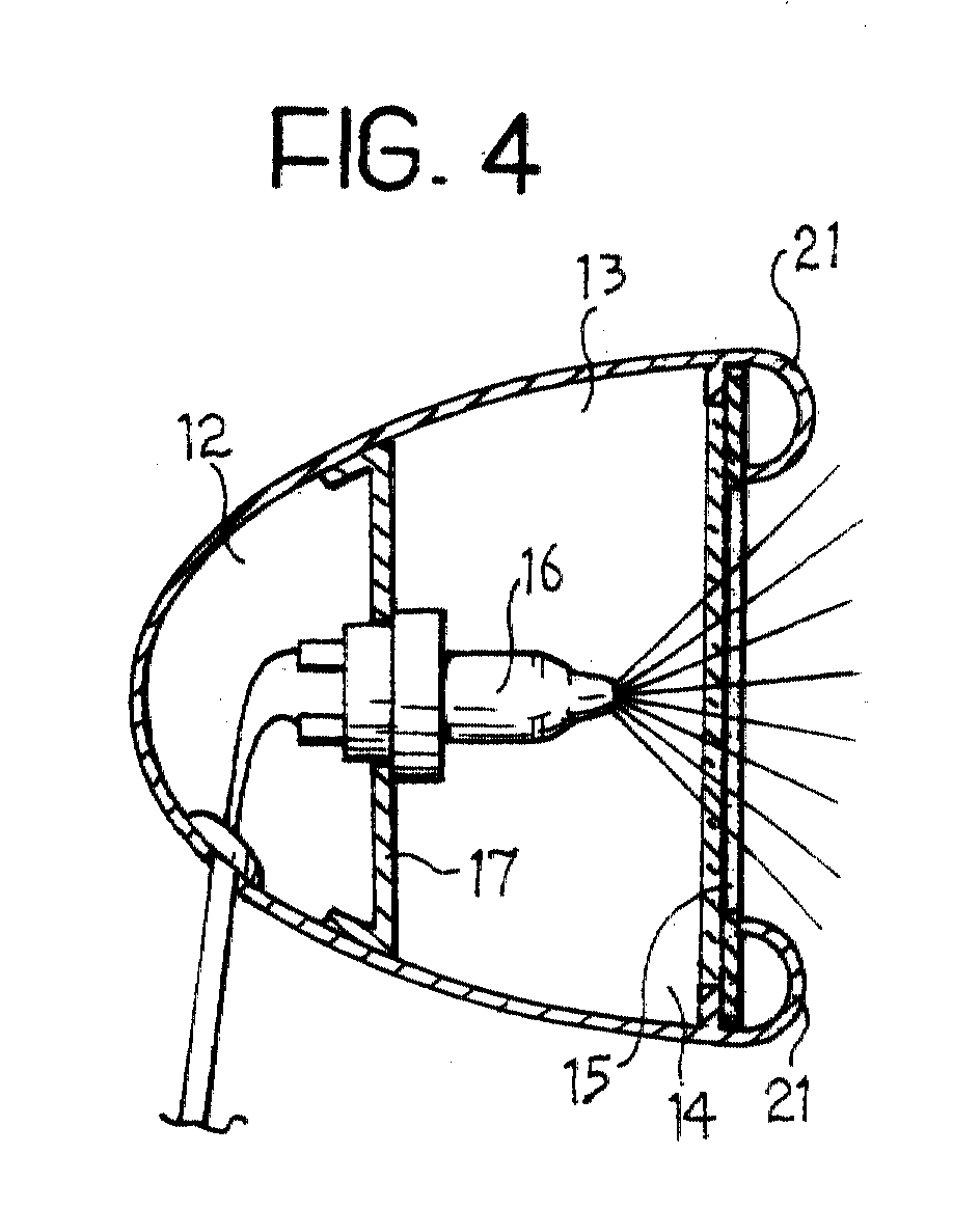
- Figure 4 shows the device of Figure 3 in longitudinal vertical section.
-
- With reference initially to Figure 1, a motor vehicle, indicated 10, has an external rear-view mirror device according to the invention, generally indicated 11, mounted on one of its sides.
- With reference also to Figures 3 and 4, the
device 11 includes a substantially rigid, shell-like structure 12 defining aninternal cavity 13 having anopening 14 in which a partiallyreflective mirror element 15 is mounted. The expression "partially reflective" is intended to be interpreted herein in the sense that themirror 15 reflects the light which falls on it from the exterior, whereas it transmits to the exterior at least some of the light emitted by alamp 16 mounted in theinternal cavity 13 of theshell 12. Thelamp 16 is preferably a halogen lamp. - The
lamp 16 is supported in thecavity 13 by asupport element 17 which holds the lamp in a position in which it is substantially centred on the geometrical axis which is perpendicular and central with respect to the plane in which the opening 14 lies. - In a possible alternative embodiment of the invention (not shown), the
support element 17 may be adjustable by means of an electrical control disposed in the passenger compartment in a similar manner to devices commonly used for adjusting the inclination of rear-view mirrors; since these devices are known in the art, they need not be described in detail herein. - The
lamp 16 is switched on and off from inside the passenger compartment by means of a suitable push-button (not shown). - With reference to Figures 1 and 2, the
device 11 can be rotated from an operative, travelling position (Figure 1), in which it has the function of a rear-view mirror, to a position to which it is rotated downwards (Figure 2) and in which it has the function of a lamp for illuminating the ground and the side door of the vehicle. - Naturally, the restraint system for the articulated mounting of the
device 11 on thevehicle 10 may be formed in various different ways, for example, by means of hinges, articulated joints, swivel joints and equivalent systems, as is known to those skilled in the art; for example, it is possible to use a bayonet joint which allows thedevice 11 to be locked in the normal travelling position of Figure 1 and to be rotated downwards to the position of Figure 2, or to adopt yet further orientations, for example, for directing the light forwards. - In the embodiment shown in Figure 3, a pair of
tabs 18 extends downwards from theshell 12;arcuate slots 19 are formed in thetabs 18 and ahorizontal support bracket 20 projecting from the side of the vehicle or from the side door is engaged therein. - In a preferred embodiment of the invention, the
device 11 is mounted on thecar 10 releasably so as to be detachable therefrom for use as an electric torch. For this purpose, thecavity 13 is arranged for housing a battery (not shown), which is preferably rechargeable by means of a conductor wire that connects the battery to the electrical system of the vehicle, in the mounted condition. - With further reference to Figure 4, the
mirror 15 is preferably held on theshell 12 releasably by means of quick-clamping means such as resilientlyflexible tabs 21 that enable themirror 15 to be removed quickly when necessary in order to replace thelamp 16. - According to a further embodiment (not shown) the device of the present invention has an electrically-operated actuator for pivoting it selectively between the positions of Figures 1 and 2.
Claims (9)
- An external rear-view mirror device (11) for a motor vehicle (10), characterized in that it comprises:a support structure (12) in which is defined a cavity (13) having an opening (14),a light source (16) which is mounted in the cavity (13) and can emit a light beam that can emerge from the cavity (13) through the opening (14), anda partially reflective element (15) which is mounted on the structure (12) in the opening (14), and which can reflect light that falls onto it from the exterior and can transmit to the exterior at least some of the light emitted by the source (16).
- A device according to Claim 1, characterized in that it has a restraining means (18, 19) for mounting the device (11) on the vehicle (10) in an articulated manner, so that the device can adopt a first operative position in which the partially reflective element (15) faces rearwardly and at least one second operative position in which the light beam emitted by the source (16) is directed in a direction other than the rearward direction.
- A device according to Claim 2, characterized in that, in the second operative position, the light beam is directed substantially downwards.
- A device according to Claim 1, characterized in that it has a restraining means for mounting the device (11) on the vehicle (10) in a releasable and separable manner.
- A device according to Claim 4, characterized in that the cavity (13) is arranged for housing a battery.
- A device according to Claim 2, characterized in that it has electric actuating means for moving the device (11) between the first and second operative positions.
- A device according to Claim 1, characterized in that the light source (16) is a halogen lamp.
- A device according to Claim 1, characterized in that the reflective element (15) is held on the support structure (12) releasably by quick clamping means (21).
- A device according to Claim 1, characterized in that the support structure (12) comprises a shell (12) defining the cavity (13).
Applications Claiming Priority (2)
| Application Number | Priority Date | Filing Date | Title |
|---|---|---|---|
| IT2000TO000546A IT1320411B1 (en) | 2000-06-08 | 2000-06-08 | EXTERNAL REARVIEW MIRROR DEVICE FOR VEHICLE. |
| ITTO000546 | 2000-06-08 |
Publications (2)
| Publication Number | Publication Date |
|---|---|
| EP1162114A2 true EP1162114A2 (en) | 2001-12-12 |
| EP1162114A3 EP1162114A3 (en) | 2002-01-23 |
Family
ID=11457799
Family Applications (1)
| Application Number | Title | Priority Date | Filing Date |
|---|---|---|---|
| EP01113383A Withdrawn EP1162114A3 (en) | 2000-06-08 | 2001-06-01 | 'An external rear-view mirror for a motor vehicle' |
Country Status (2)
| Country | Link |
|---|---|
| EP (1) | EP1162114A3 (en) |
| IT (1) | IT1320411B1 (en) |
Cited By (1)
| Publication number | Priority date | Publication date | Assignee | Title |
|---|---|---|---|---|
| FR2941188A1 (en) * | 2009-01-16 | 2010-07-23 | Peugeot Citroen Automobiles Sa | Outside left and right rear view mirror for vehicle i.e. motor vehicle, has lighting unit integrated in glass, where lightning unit is constituted by optical assembly comprising light source i.e. LED, and concave reflecting mirror |
Family Cites Families (3)
| Publication number | Priority date | Publication date | Assignee | Title |
|---|---|---|---|---|
| JP2960736B2 (en) * | 1989-04-10 | 1999-10-12 | スタンレー電気株式会社 | Backlight for vehicles |
| JPH0971176A (en) * | 1995-06-30 | 1997-03-18 | Honda Access Corp | Door mirror composite device with illumination |
| US6079858A (en) * | 1998-08-17 | 2000-06-27 | Lear Automotive Dearborn, Inc. | Side view mirror with detachable flashlight |
-
2000
- 2000-06-08 IT IT2000TO000546A patent/IT1320411B1/en active
-
2001
- 2001-06-01 EP EP01113383A patent/EP1162114A3/en not_active Withdrawn
Non-Patent Citations (1)
| Title |
|---|
| None |
Cited By (1)
| Publication number | Priority date | Publication date | Assignee | Title |
|---|---|---|---|---|
| FR2941188A1 (en) * | 2009-01-16 | 2010-07-23 | Peugeot Citroen Automobiles Sa | Outside left and right rear view mirror for vehicle i.e. motor vehicle, has lighting unit integrated in glass, where lightning unit is constituted by optical assembly comprising light source i.e. LED, and concave reflecting mirror |
Also Published As
| Publication number | Publication date |
|---|---|
| ITTO20000546A1 (en) | 2001-12-08 |
| IT1320411B1 (en) | 2003-11-26 |
| EP1162114A3 (en) | 2002-01-23 |
| ITTO20000546A0 (en) | 2000-06-08 |
Similar Documents
| Publication | Publication Date | Title |
|---|---|---|
| US4511954A (en) | Visor with auxiliary light | |
| US6175300B1 (en) | Blind spot viewing system | |
| US4824159A (en) | Pivoted rotatable illuminated rear seat vanity mirror | |
| US10926704B2 (en) | Exterior rearview mirror with constant ground illumination | |
| JP3911241B2 (en) | Vehicle headlamp | |
| JP2004082829A (en) | In-vehicle camera | |
| GB2210835A (en) | Vehicle forward view mirror | |
| US20090086346A1 (en) | Side mirror assembly for a motor vehicle | |
| US4832476A (en) | Blind spot viewing mirror system | |
| JP2006145895A (en) | Camera head | |
| US6511189B1 (en) | Interchangeable mirror scalp for trailer towing | |
| EP1162114A2 (en) | 'An external rear-view mirror for a motor vehicle' | |
| US6986596B2 (en) | Exterior rearview mirror assembly | |
| US6264339B1 (en) | Make-up mirror for vehicle | |
| JP2014168169A (en) | Image display system for vehicle | |
| JPH11321307A (en) | Visor with swiveling vanity mirror assembly | |
| GB2236291A (en) | An external rear-view mirror for motor vehicles | |
| KR20010006437A (en) | Interior Rearview Mirror for a Vehicle, and Actuator for an Interior Rearview Mirror | |
| WO2001028814A2 (en) | Interchangeable mirror scalp for trailer towing | |
| EP1232072B1 (en) | Vehicle side mirror assembly with integral illumination and signal lighting | |
| EP1334873B1 (en) | Vehicle rear view mirror assembly | |
| JP3232432U (en) | Automotive side and rear lighting | |
| US20050052762A1 (en) | Method and apparatus for safely backing a vehicle into a traffic lane | |
| KR0131787Y1 (en) | Motorized door back mirror of car with square mirror | |
| US20040042099A1 (en) | Blind spot mirror |
Legal Events
| Date | Code | Title | Description |
|---|---|---|---|
| PUAI | Public reference made under article 153(3) epc to a published international application that has entered the european phase |
Free format text: ORIGINAL CODE: 0009012 |
|
| PUAL | Search report despatched |
Free format text: ORIGINAL CODE: 0009013 |
|
| AK | Designated contracting states |
Kind code of ref document: A2 Designated state(s): AT BE CH CY DE DK ES FI FR GB GR IE IT LI LU MC NL PT SE TR |
|
| AX | Request for extension of the european patent |
Free format text: AL;LT;LV;MK;RO;SI |
|
| AK | Designated contracting states |
Kind code of ref document: A3 Designated state(s): AT BE CH CY DE DK ES FI FR GB GR IE IT LI LU MC NL PT SE TR |
|
| AX | Request for extension of the european patent |
Free format text: AL;LT;LV;MK;RO;SI |
|
| 17P | Request for examination filed |
Effective date: 20020711 |
|
| AKX | Designation fees paid |
Free format text: AT BE CH CY DE DK ES FI FR GB GR IE IT LI LU MC NL PT SE TR |
|
| 17Q | First examination report despatched |
Effective date: 20030403 |
|
| STAA | Information on the status of an ep patent application or granted ep patent |
Free format text: STATUS: THE APPLICATION IS DEEMED TO BE WITHDRAWN |
|
| 18D | Application deemed to be withdrawn |
Effective date: 20031014 |