EP1162027A1 - Tool pot for tool magazine - Google Patents
Tool pot for tool magazine Download PDFInfo
- Publication number
- EP1162027A1 EP1162027A1 EP01106697A EP01106697A EP1162027A1 EP 1162027 A1 EP1162027 A1 EP 1162027A1 EP 01106697 A EP01106697 A EP 01106697A EP 01106697 A EP01106697 A EP 01106697A EP 1162027 A1 EP1162027 A1 EP 1162027A1
- Authority
- EP
- European Patent Office
- Prior art keywords
- tool
- tool pot
- pot
- main body
- pot according
- Prior art date
- Legal status (The legal status is an assumption and is not a legal conclusion. Google has not performed a legal analysis and makes no representation as to the accuracy of the status listed.)
- Granted
Links
- 239000003365 glass fiber Substances 0.000 claims abstract description 37
- 229920005992 thermoplastic resin Polymers 0.000 claims abstract description 22
- 229920005989 resin Polymers 0.000 claims abstract description 7
- 239000011347 resin Substances 0.000 claims abstract description 7
- 239000012815 thermoplastic material Substances 0.000 claims description 6
- 239000000463 material Substances 0.000 abstract description 13
- KXGFMDJXCMQABM-UHFFFAOYSA-N 2-methoxy-6-methylphenol Chemical compound [CH]OC1=CC=CC([CH])=C1O KXGFMDJXCMQABM-UHFFFAOYSA-N 0.000 description 9
- 229920001568 phenolic resin Polymers 0.000 description 9
- 239000005011 phenolic resin Substances 0.000 description 9
- 101100298222 Caenorhabditis elegans pot-1 gene Proteins 0.000 description 5
- 239000002184 metal Substances 0.000 description 5
- 239000004743 Polypropylene Substances 0.000 description 3
- XECAHXYUAAWDEL-UHFFFAOYSA-N acrylonitrile butadiene styrene Chemical compound C=CC=C.C=CC#N.C=CC1=CC=CC=C1 XECAHXYUAAWDEL-UHFFFAOYSA-N 0.000 description 3
- 239000004676 acrylonitrile butadiene styrene Substances 0.000 description 3
- 229920000122 acrylonitrile butadiene styrene Polymers 0.000 description 3
- 229920006038 crystalline resin Polymers 0.000 description 3
- 229920001707 polybutylene terephthalate Polymers 0.000 description 3
- 239000004417 polycarbonate Substances 0.000 description 3
- -1 polyethylene terephthalate Polymers 0.000 description 3
- 229920000139 polyethylene terephthalate Polymers 0.000 description 3
- 239000005020 polyethylene terephthalate Substances 0.000 description 3
- 229920002302 Nylon 6,6 Polymers 0.000 description 2
- 229920006127 amorphous resin Polymers 0.000 description 2
- 230000006835 compression Effects 0.000 description 2
- 238000007906 compression Methods 0.000 description 2
- 238000001746 injection moulding Methods 0.000 description 2
- 230000002093 peripheral effect Effects 0.000 description 2
- 230000003252 repetitive effect Effects 0.000 description 2
- 229920002292 Nylon 6 Polymers 0.000 description 1
- 238000010276 construction Methods 0.000 description 1
- 238000005520 cutting process Methods 0.000 description 1
- 230000000694 effects Effects 0.000 description 1
- 238000010348 incorporation Methods 0.000 description 1
- 238000003754 machining Methods 0.000 description 1
- 238000004519 manufacturing process Methods 0.000 description 1
- 239000012778 molding material Substances 0.000 description 1
- 230000010355 oscillation Effects 0.000 description 1
- 239000012994 photoredox catalyst Substances 0.000 description 1
- 229920000515 polycarbonate Polymers 0.000 description 1
- 229920001155 polypropylene Polymers 0.000 description 1
- 229920001187 thermosetting polymer Polymers 0.000 description 1
- 238000005303 weighing Methods 0.000 description 1
Images



Classifications
-
- B—PERFORMING OPERATIONS; TRANSPORTING
- B23—MACHINE TOOLS; METAL-WORKING NOT OTHERWISE PROVIDED FOR
- B23Q—DETAILS, COMPONENTS, OR ACCESSORIES FOR MACHINE TOOLS, e.g. ARRANGEMENTS FOR COPYING OR CONTROLLING; MACHINE TOOLS IN GENERAL CHARACTERISED BY THE CONSTRUCTION OF PARTICULAR DETAILS OR COMPONENTS; COMBINATIONS OR ASSOCIATIONS OF METAL-WORKING MACHINES, NOT DIRECTED TO A PARTICULAR RESULT
- B23Q3/00—Devices holding, supporting, or positioning work or tools, of a kind normally removable from the machine
- B23Q3/155—Arrangements for automatic insertion or removal of tools, e.g. combined with manual handling
- B23Q3/1552—Arrangements for automatic insertion or removal of tools, e.g. combined with manual handling parts of devices for automatically inserting or removing tools
- B23Q3/15526—Storage devices; Drive mechanisms therefor
-
- B—PERFORMING OPERATIONS; TRANSPORTING
- B23—MACHINE TOOLS; METAL-WORKING NOT OTHERWISE PROVIDED FOR
- B23Q—DETAILS, COMPONENTS, OR ACCESSORIES FOR MACHINE TOOLS, e.g. ARRANGEMENTS FOR COPYING OR CONTROLLING; MACHINE TOOLS IN GENERAL CHARACTERISED BY THE CONSTRUCTION OF PARTICULAR DETAILS OR COMPONENTS; COMBINATIONS OR ASSOCIATIONS OF METAL-WORKING MACHINES, NOT DIRECTED TO A PARTICULAR RESULT
- B23Q13/00—Equipment for use with tools or cutters when not in operation, e.g. protectors for storage
-
- B—PERFORMING OPERATIONS; TRANSPORTING
- B23—MACHINE TOOLS; METAL-WORKING NOT OTHERWISE PROVIDED FOR
- B23Q—DETAILS, COMPONENTS, OR ACCESSORIES FOR MACHINE TOOLS, e.g. ARRANGEMENTS FOR COPYING OR CONTROLLING; MACHINE TOOLS IN GENERAL CHARACTERISED BY THE CONSTRUCTION OF PARTICULAR DETAILS OR COMPONENTS; COMBINATIONS OR ASSOCIATIONS OF METAL-WORKING MACHINES, NOT DIRECTED TO A PARTICULAR RESULT
- B23Q3/00—Devices holding, supporting, or positioning work or tools, of a kind normally removable from the machine
- B23Q3/155—Arrangements for automatic insertion or removal of tools, e.g. combined with manual handling
- B23Q3/1552—Arrangements for automatic insertion or removal of tools, e.g. combined with manual handling parts of devices for automatically inserting or removing tools
- B23Q3/15526—Storage devices; Drive mechanisms therefor
- B23Q2003/15532—Storage devices; Drive mechanisms therefor the storage device including tool pots, adaptors or the like
-
- Y—GENERAL TAGGING OF NEW TECHNOLOGICAL DEVELOPMENTS; GENERAL TAGGING OF CROSS-SECTIONAL TECHNOLOGIES SPANNING OVER SEVERAL SECTIONS OF THE IPC; TECHNICAL SUBJECTS COVERED BY FORMER USPC CROSS-REFERENCE ART COLLECTIONS [XRACs] AND DIGESTS
- Y10—TECHNICAL SUBJECTS COVERED BY FORMER USPC
- Y10S—TECHNICAL SUBJECTS COVERED BY FORMER USPC CROSS-REFERENCE ART COLLECTIONS [XRACs] AND DIGESTS
- Y10S279/00—Chucks or sockets
- Y10S279/90—Adapted for automatic tool changer
-
- Y—GENERAL TAGGING OF NEW TECHNOLOGICAL DEVELOPMENTS; GENERAL TAGGING OF CROSS-SECTIONAL TECHNOLOGIES SPANNING OVER SEVERAL SECTIONS OF THE IPC; TECHNICAL SUBJECTS COVERED BY FORMER USPC CROSS-REFERENCE ART COLLECTIONS [XRACs] AND DIGESTS
- Y10—TECHNICAL SUBJECTS COVERED BY FORMER USPC
- Y10S—TECHNICAL SUBJECTS COVERED BY FORMER USPC CROSS-REFERENCE ART COLLECTIONS [XRACs] AND DIGESTS
- Y10S483/00—Tool changing
- Y10S483/902—Tool grippers
-
- Y—GENERAL TAGGING OF NEW TECHNOLOGICAL DEVELOPMENTS; GENERAL TAGGING OF CROSS-SECTIONAL TECHNOLOGIES SPANNING OVER SEVERAL SECTIONS OF THE IPC; TECHNICAL SUBJECTS COVERED BY FORMER USPC CROSS-REFERENCE ART COLLECTIONS [XRACs] AND DIGESTS
- Y10—TECHNICAL SUBJECTS COVERED BY FORMER USPC
- Y10T—TECHNICAL SUBJECTS COVERED BY FORMER US CLASSIFICATION
- Y10T483/00—Tool changing
- Y10T483/18—Tool transfer to or from matrix
-
- Y—GENERAL TAGGING OF NEW TECHNOLOGICAL DEVELOPMENTS; GENERAL TAGGING OF CROSS-SECTIONAL TECHNOLOGIES SPANNING OVER SEVERAL SECTIONS OF THE IPC; TECHNICAL SUBJECTS COVERED BY FORMER USPC CROSS-REFERENCE ART COLLECTIONS [XRACs] AND DIGESTS
- Y10—TECHNICAL SUBJECTS COVERED BY FORMER USPC
- Y10T—TECHNICAL SUBJECTS COVERED BY FORMER US CLASSIFICATION
- Y10T483/00—Tool changing
- Y10T483/18—Tool transfer to or from matrix
- Y10T483/1809—Matrix including means to latch tool
-
- Y—GENERAL TAGGING OF NEW TECHNOLOGICAL DEVELOPMENTS; GENERAL TAGGING OF CROSS-SECTIONAL TECHNOLOGIES SPANNING OVER SEVERAL SECTIONS OF THE IPC; TECHNICAL SUBJECTS COVERED BY FORMER USPC CROSS-REFERENCE ART COLLECTIONS [XRACs] AND DIGESTS
- Y10—TECHNICAL SUBJECTS COVERED BY FORMER USPC
- Y10T—TECHNICAL SUBJECTS COVERED BY FORMER US CLASSIFICATION
- Y10T483/00—Tool changing
- Y10T483/18—Tool transfer to or from matrix
- Y10T483/1864—Tool transfer to or from matrix including tool pot or adapter
Definitions
- the invention relates to a tool pot for a tool magazine for removably holding a plurality of tools.
- a plurality of tool pots are supported on an outer periphery of a magazine disc that is indexically rotated, and a tool is inserted into a holding aperture formed in each of the tool pots.
- a key protruding from an opening end face of the holding aperture then engages a key groove formed in the tool, and the tool is removably held in the tool pot while being stopped from rotation.
- a tool to be used next is unloaded from the magazine disc at a tool unloading position and swiveled by 90° to be parallel a rotational axis of the tool with a spindle of the machine tool.
- the tool held in the tool pot and a tool hold in the spindle are simultaneously exchanged by an automatic tool changer.
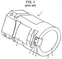
- a main body 5 of such a tool pot 1 has previously been molded from a phenolic resin. Because the phenolic resin is not great in impact strength, a metal key member 2 is fastened by means of a screw 3 to the outer peripheral face at an opening end of a holding aperture 4 formed in the main body 5, and a key portion 6 of the key member 2 protrudes outside of an opening end face 7 of the holding aperture 4.
- the metal key member 2 is fastened to the tool pot 1 by the screw 3
- the overall man-hour of assembling increases, and the head of the screw 3 causes wear to in a resinous guide plate for guiding the tool pot 1.
- the tool pot 1 is thick in a radial direction as a whole because of the necessity to increase rigidity. This makes it impossible to reduce its weight sufficiently. Also, because the phenolic resin is a thermosetting resin, the tool pot 1 cannot be recycled once it has become unusable due to wear.
- the invention has been made to solve the problems stated above. It is an object of the invention to provide a tool pot that is lightweight and recyclable.
- the invention provides a tool pot that is used for a tool magazine of a machine tool to attachablely hold a tool, wherein a holding aperture for holding the tool is formed in a main body of the tool pot.
- the main body of the tool pot is formed of a glass-fiber reinforced thermoplastic material composed of a thermoplastic resin containing a glass fiber.
- the main body of the tool pot is formed of a glass-fiber reinforced thermoplastic material composed of a thermoplastic resin containing a glass fiber, it is possible to provide a tool pot that is lightweight and recyclable.
- a tool pot comprises a main body having a holding aperture for holding a tool and a key that is disposed on an opening end face of the holding aperture and that engages a key groove formed in the tool to stop rotation of the tool.
- the main body and the key are integrally molded from a glass-fiber reinforced thermoplastic material composed of a thermoplastic resin containing a glass fiber.
- the aforementioned construction eliminates the necessity to fasten the metal key member, it is possible to manufacture the key easily and at a low cost. Further, when the head of the screw for fastening the key member moves along the resinous guide plate for guiding the tool pot, no wear is caused.
- FIG. 2 A tool magazine attachment equipped with a tool pot according to the invention will be described with reference to Figs. 2, 3.
- a column 10 is guided and supported on a bed (not shown) such that the column 10 can slide in a direction of an X-axis by a servo motor (not shown).
- the column 10 is moved to a tool exchanging portion P2 shown in Fig. 2.
- a spindle head 11 is vertically slidably guided and supported on a front face of the column 10. The spindle head 11 is moved by a servo motor (not shown) in a vertical direction.
- a spindle 12 is rotatably supported by the spindle head 11 around an axis parallel to the Z-axis and rotationally driven by a spindle motor (not shown).
- a tool 13 is removably fitted to a tip of the spindle 12.
- the tool 13 is constructed of a tool holder to which a cutting tool such as a drill is fitted.
- An automatic tool changer (hereinafter "ATC") 20 is installed on the bed between the column 10 positioned at the tool exchanging position P2 and a later-described tool magazine 30.
- the ATC 20 is composed of a tool exchanging arm 21 and a drive unit (not shown).
- the tool exchanging arm 21 has at its opposed ends grips 22 for gripping the tool 13, and can rotate around an axis H parallel to the spindle 12 and move along the axis H.
- the drive unit has a cam mechanism that rotates the tool exchanging arm 21 in normal and reverse directions by a predetermined angle and moves it forwards and backwards by a predetermined distance.
- a magazine disc 32 that serves as an indexing rotor of the magazine, is supported on a stationary base 31 disposed in a standing manner on the bed, such that the magazine disc 32 is capable of indexical rotation around a horizontal axis parallel to the X-axis.
- the magazine disc 32 is indexically rotated by an indexing motor 33.
- a plurality of rectangular pot containers 34 are provided at equal intervals along the circumference of the magazine disc 32.
- Each of engaging grooves 51 formed in a tool pot 50 radially removably engage an engaging portion 35 protruding from the inside of the pot container 34.
- a stationary guide rail 36 is so attached to the stationary base 31 as to surround the pot containers 34 of the magazine disc 32.
- the guide rail 36 prevents the tool pot 50 from moving away from the relevant pot container 34.
- the guide rail 36 and the stationary base 31 are notched at a tool unloading position P0, so that the tool pot 50 can be unloaded from the magazine disc 32.
- the stationary base 31 is provided with a pot transfer unit 40 for transferring the tool pot 50 from the tool unloading position P0 to the tool exchanging position P1.
- a rotational shaft 42 is supported by the stationary base 31 through a bracket such that the rotational shaft 42 can rotate around the vertical axis.
- a pair of hooks 41 disposed in coordination with the notch in the guide rail 36 (the tool unloading position P0) are fixed by a root 44.
- the hooks 41 have guides 43 that engage hook engaging grooves 52 formed in the tool pot 50 so as to sandwich from opposed sides the tool pot 50 that passes the tool unloading position P0 as the magazine disc 32 rotates.
- a rotational plate 45 is securely fitted to the upper end of the rotational shaft 42.
- the tip of a piston rod of a hook swiveling cylinder 46 is swingingly supported by the rotational plate 45 through a pin 48.
- the hook swiveling cylinder 46 is supported at one end by the stationary base 31 such that the hook swiveling cylinder 46 can rotate around an axis parallel to the Y-axis.
- the hooks 41 are swiveled by 90° together with the rotational shaft 42 due to the operation of the hook swiveling cylinder 46.
- the tool pot 50 is guided and supported by a pair of upper and lower guide plates 47 disposed in the notch of the guide rail 36 when it is transferred from the tool unloading position P0 to the tool exchanging position P1.
- a guide 49 secured to the hooks 41 is aligned with the notch in the guide rail 36 when the hooks 41 are swiveled to the tool exchanging position P1.
- the guide 49 prevents the tool pot 50 from moving away from the relevant pot container 34 when the magazine disc 32 is indexically rotated.
- a main body 53 of the tool pot 50 is integrally molded from a glass-fiber reinforced thermoplastic resin material.
- a main body 53 is constructed with a cylindrical wall 58, two end ribs 55, 56 and four longitudinal ribs 57.
- the cylindrical wall 58 provides a taped aperture 54 for holding the tool 13 in the center portion.
- the end rib 55 is an annular shape and formed at the front end of the cylindrical wall 58.
- the end rib 56 is a shape of generally square cross-section and formed at the rear end of a main body 53.
- the longitudinal ribs 57 are so formed as to connect the ribs 55, 56 with each other.
- the engaging grooves 51 are formed in the ribs 55, 56 on each lateral face of the main body 53.
- the engaging portion 35 protruding from the inside of each of the pot containers 34 removably engages the engaging grooves 51.
- a taper 59 is formed at the end of each of the engaging grooves 51 on the side of the magazine disc 32 with a view to facilitating engagement with the engaging portion 35 and disengagement therefrom.
- the hook engaging grooves 52 are formed in the other opposed faces of the rib 56 at the rear end of the main body 53.
- the hook engaging grooves 52 extend in a direction perpendicular to the axis of the holding aperture 54, and are engaged with the guides 43 of the hooks 41 and disengaged therefrom.
- a key 60 is integrally molded on the front end face of the main body 53 where the holding aperture 54 opens.
- the key 60 engages a key groove formed in the tool 13 and stops rotation of the tool 13 that has been inserted into the holding aperture 54 and held by the tool pot 50.
- a metal ring 61 is fused to a rear-end small-diameter portion of the holding aperture 54 as shown in Fig. 5.
- Four detent holes 62 are formed in the outer peripheral face of the rib 56 so as to radially extend towards the ring 61.
- the detent holes 62 communicate with four ball support holes 63 formed in the ring 61 respectively.
- a ball 64 is loosely fitted in each of the ball support holes 63.
- a compression spring 66 is interposed between the ball 64 and a shrouding member 65 screwed into the detent hole 62.
- the ball 64 is urged inwards by the compression spring 66, partially protrudes to the radially inner side of the ring 61, removably engages a pull stud 67 of the tool 13 that has been inserted into the holding aperture 54, and hence prevents the tool 13 from falling off.
- the main body 53 is integrally molded through the injection molding of a glass-fiber reinforced thermoplastic resin material. It is almost unnecessary to machine the main body 53 except the detent holes 62 at the rear end and threaded grooves into which the shrouding members 65 are screwed.
- the glass-fiber reinforced thermoplastic resin material used herein contains 30 weight percent of a glass fiber having a length of 200 ⁇ m to 300 ⁇ m and a diameter of 10 ⁇ m to 15 ⁇ m in N66 (polyamide 66), which is a nylon-type resin. Dies are maintained in a temperature range of 80°C to 120°C during the injection molding, whereby it becomes possible to enhance the modulus of elasticity and the tensile strength by 8 percent.
- the tool pot 50 thus molded is about four times as great in tensile strength and about ten times as great in impact strength as the prior-art tool pot molded from a phenolic resin.
- the flexural modulus of the glass-fiber reinforced thermoplastic resin material rises from a point where the content of the glass fiber is about 15 percent, but falls after the content of the glass fiber exceeds 45 percent. This is because glass fibers interfere with one another and eventually break at the content exceeding 45 percent.
- N6 polyamide 6
- PET polyethylene terephthalate
- PBT polybutylene terephthalate
- PP polypropylene
- PC polycarbonate
- ABS acrylonitrile-butadiene-styrene
- thermoplastic resin materials containing crystalline resins such as N66, N6, PET, PBT and PP are more remarkable than those containing amorphous resins such as ABS and PC, for the effects associated with the inclusion of glass fibers, such as the increase of tensile strength and the enhancement of the temperature range suited for continuous use (In Fig. 7, white circles show tensile strength and the enhancement of the temperature range suited for continuous use of no inclusion glass fibers, and black circles show the same inclusion glass fibers). Therefore, the materials containing crystalline resin are better suited to mold the main body 53.
- the column 10 in order to exchange the tool 13 fitted to the spindle 12 and a tool 13 to be used next (hereinafter "next tool"), the column 10 is transferred to the tool exchanging position P2 shown in Fig. 2, and the tool pot 50 holding the next tool 13 is transferred by the pot transferring unit 40 from the tool unloading position P0 to the tool exchanging position P1.
- the magazine disc 32 is indexically rotated with the pot transferring unit 40 at the tool unloading position P0, the tool pots 50 contained in the pot containers 34 are sequentially indexed at the tool unloading position P0 while being guided by the stationary guide rail 36, and proceed while being guided by the guides 43 of the hooks 41 located at the tool unloading position P0.
- the tool pot 50 holding the next tool 13 is indexed at the tool unloading position P0, indexical rotation of the magazine disc 32 is stopped, and the hooks 41 are swiveled by 90° by the hook swiveling cylinder 46. As the hooks 41 are swiveled, the tool pot 50 is removed from the pot container 34 of the magazine disc 32 and swiveled while being guided by the guide plates 47.
- the tool exchanging arm 21 of the ATC 20 then rotates counterclockwise by a predetermined angle, and the grips 22 provided at the opposed ends of the arm hold the tool 13 fitted to the spindle 12 and the next tool 13 that has been transferred to the tool exchanging position P1.
- each whirl-stop key 23 on the grips 22 engages one of the key grooves formed in each of the tools 13.
- the other key grooves formed in the tools 13 engage the key 60 of the tool pot 50 and the key 25 of the spindle 12 respectively (see Fig. 9).
- the tool exchanging arm 21 thereafter proceeds forwards, draws the tools 13 out of the tool fitting aperture at the tip of the spindle 12 and the holding aperture 54 of the tool pot 50, rotates by 180°, and retreats.
- the tools 13 are exchanged between the spindle 12 and the tool pot 50.
- the key 60 of the tool pot 50 is engaged with and disengaged from the key grooves formed in the tools 13, the key 60 may partially impact against the key grooves.
- the key 60 is integrated with the main body 53 molded from the glass-fiber reinforced thermoplastic resin material, and is about ten times as great in impact strength as the phenolic resin. Therefore, the key 60 is unsusceptible to damages.
- the magazine disc 32 is indexically rotated such that the pot container 34 containing the tool pot 50 for holding the tool 13 previously fitted to the spindle 12 is indexed at the tool unloading position P0.
- the column 10 is restored to a machining position.
- the tool pot 50 for holding the tool 13 previously fitted to the spindle 12 is then returned from the tool exchanging position P1 to the tool unloading position P0 to be contained in the pot container 34 corresponding to the tool 13.
- the tool pot 50 is transferred in a sliding manner, the tool pot 50 is ground against some portions which are the guide rail 36 of the tool magazine 30, the engaging portion 35 of the pot container 34, the guides 43 of hooks 41 and the guide plates 47. It is considered that amount of wear at sides portion of the engaging grooves 51 formed in the rib 56 at the rear end sliding to the engaging portion 35 is larger than other portions, because the tool pot 50 is turned in small radius during transferring from the tool unloading position P0 to the tool exchanging position P1. Thus, a repetitive wear test of the engaging groove 51 of the rib 56 has been conducted by loading the tool pot 50 into the pot container 34 and unloading it therefrom one hundred fifty thousand times.
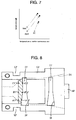
- the engaging groove 51 of the rib 56 is substantially reduced in the degree of wear at six locations (A1, A2, B1, B2, C1, C2) shown in Fig. 8 in comparison with the tool pot made of the phenolic resin, as is apparent from a table shown below.
- the main body 53 which is molded from a glass-fiber reinforced thermoplastic resin material composed of a thermoplastic resin containing a glass fiber, can be recycled. Furthermore, in the tool pot made of the phenolic resin, when the tool pot 50 is swiveled while being guided by the guide plate 47, the head of the screw for fastening the metal key member to the main body is ground against the surface of the guide plate 47 and causes wear. However, in the tool pot 50, since the key 60 is integrated with the main body 53, the sliding movements between the resin materials do not cause wear of the guide plate 47.
- the main body 53 is composed of the ribs 55, 56, the axial rib 57 and the thin cylindrical wall 58, and the tool 13 is held in the holding aperture 54 with the thin wall serving to absorb oscillation. Therefore, the tool 13 is prevented from falling off from the tool pot 50 during the indexical rotation of the magazine disc 32 and the transfer operation performed by the pot transfer unit 40. Because the main body 53 is slimmed down by being composed of the ribs and the thin wall, the required amount of the molding material is reduced. This makes the tool pot 50 lightweight and inexpensive and enhances the energy efficiency of rotating the tool magazine 30.
- the spindle 12 is substantially as high as the tool pot 50 that has been transferred to the tool exchanging position P1 in the horizontal direction.
- the tool magazine 30 and the pot transfer unit 40 of this type if the tool exchanging arm 21 is rotated counterclockwise by a predetermined angle as shown in Fig. 9, a whirl-stop key 23 of the grip 22 engages from above one of the key grooves in the tool 13 held by the tool pot 50.
- the key 60 of the tool pot 50 engages the other key groove in the tool 13 below, whereby the tool 13 is positioned.
- the keys 60, 68 of the tool pots 50 are different only in phase angle and identical in other respects, a great number of main bodies 53 having the keys 60, 68 may be molded, and those keys which do not suit the tool magazine employing the tool pots 50 may be removed by being cut off.
- a tool pot used for a tool magazine of a machine tool to removably hold a tool is disclosed.
- a main body of the tool pot is constructed a cylindrical wall defining a holding aperture for holding the tool, end ribs formed at opposed ends of the cylindrical wall and a plurality of longitudinal ribs formed between the end ribs on the outer periphery of the cylindrical wall.
- the main body is integrally molded from a glass-fiber reinforced thermoplastic resin material such as crystalline nylon-type resin. Therefore, the tool pot has high wear resistance and light weight, and it can be recycled.
Landscapes
- Engineering & Computer Science (AREA)
- Mechanical Engineering (AREA)
- Automatic Tool Replacement In Machine Tools (AREA)
- Compositions Of Macromolecular Compounds (AREA)
Abstract
Description
- The disclosure of Japanese Patent Application No. 2000-171130 filed on June 7, 2000 is incorporated herein by reference in its entirety.
- The invention relates to a tool pot for a tool magazine for removably holding a plurality of tools.
- In general, in a tool magazine for a machine tool such as a machining center, a plurality of tool pots are supported on an outer periphery of a magazine disc that is indexically rotated, and a tool is inserted into a holding aperture formed in each of the tool pots. A key protruding from an opening end face of the holding aperture then engages a key groove formed in the tool, and the tool is removably held in the tool pot while being stopped from rotation. A tool to be used next is unloaded from the magazine disc at a tool unloading position and swiveled by 90° to be parallel a rotational axis of the tool with a spindle of the machine tool. The tool held in the tool pot and a tool hold in the spindle are simultaneously exchanged by an automatic tool changer.
- As shown in Fig. 1, a
main body 5 of such atool pot 1 has previously been molded from a phenolic resin. Because the phenolic resin is not great in impact strength, ametal key member 2 is fastened by means of ascrew 3 to the outer peripheral face at an opening end of aholding aperture 4 formed in themain body 5, and akey portion 6 of thekey member 2 protrudes outside of anopening end face 7 of theholding aperture 4. - In a case that the
metal key member 2 is fastened to thetool pot 1 by thescrew 3, the overall man-hour of assembling increases, and the head of thescrew 3 causes wear to in a resinous guide plate for guiding thetool pot 1. Thetool pot 1 is thick in a radial direction as a whole because of the necessity to increase rigidity. This makes it impossible to reduce its weight sufficiently. Also, because the phenolic resin is a thermosetting resin, thetool pot 1 cannot be recycled once it has become unusable due to wear. - The invention has been made to solve the problems stated above. It is an object of the invention to provide a tool pot that is lightweight and recyclable.
- In order to solve the aforementioned problems, the invention provides a tool pot that is used for a tool magazine of a machine tool to attachablely hold a tool, wherein a holding aperture for holding the tool is formed in a main body of the tool pot. The main body of the tool pot is formed of a glass-fiber reinforced thermoplastic material composed of a thermoplastic resin containing a glass fiber.
- Because the main body of the tool pot is formed of a glass-fiber reinforced thermoplastic material composed of a thermoplastic resin containing a glass fiber, it is possible to provide a tool pot that is lightweight and recyclable.
- A tool pot according to another aspect of the invention comprises a main body having a holding aperture for holding a tool and a key that is disposed on an opening end face of the holding aperture and that engages a key groove formed in the tool to stop rotation of the tool. The main body and the key are integrally molded from a glass-fiber reinforced thermoplastic material composed of a thermoplastic resin containing a glass fiber.
- Because the aforementioned construction eliminates the necessity to fasten the metal key member, it is possible to manufacture the key easily and at a low cost. Further, when the head of the screw for fastening the key member moves along the resinous guide plate for guiding the tool pot, no wear is caused.
- The foregoing and further objects, features and advantages of the present invention will become apparent from the following description of preferred embodiments with reference to the accompanying drawings, wherein:
- Fig. 1 is a perspective view of a tool pot made of a phenolic resin;
- Fig. 2 is a cross-sectional view of a tool magazine attachment equipped with a tool pot according to the invention;
- Fig. 3 is a side view seen from the direction of an arrow III in Fig. 2;
- Fig. 4 is a perspective view of a tool pot according to the invention;
- Fig. 5 is a cross-sectional view taken along a line V-V in Fig. 4;
- Fig. 6 is a graph showing a relation between contents of a glass fiber and flexural modulus of a glass-fiber reinforced thermoplastic material;
- Fig. 7 is a graph showing a relation between temperature suited for continuous use and tensile strength of a crystalline resin and an amorphous resin;
- Fig. 8 is a side view of the tool pot showing locations of an engaging groove to be measured for degrees of wear; and
- Fig. 9 is a cross-sectional view of a tool exchanging arm showing the operation thereof.
-
- A tool magazine attachment equipped with a tool pot according to the invention will be described with reference to Figs. 2, 3. In Fig. 2, a
column 10 is guided and supported on a bed (not shown) such that thecolumn 10 can slide in a direction of an X-axis by a servo motor (not shown). In exchanging tools, thecolumn 10 is moved to a tool exchanging portion P2 shown in Fig. 2. Aspindle head 11 is vertically slidably guided and supported on a front face of thecolumn 10. Thespindle head 11 is moved by a servo motor (not shown) in a vertical direction. - A
spindle 12 is rotatably supported by thespindle head 11 around an axis parallel to the Z-axis and rotationally driven by a spindle motor (not shown). Atool 13 is removably fitted to a tip of thespindle 12. Thetool 13 is constructed of a tool holder to which a cutting tool such as a drill is fitted. An automatic tool changer (hereinafter "ATC") 20 is installed on the bed between thecolumn 10 positioned at the tool exchanging position P2 and a later-describedtool magazine 30. The ATC 20 is composed of atool exchanging arm 21 and a drive unit (not shown). Thetool exchanging arm 21 has at itsopposed ends grips 22 for gripping thetool 13, and can rotate around an axis H parallel to thespindle 12 and move along the axis H. The drive unit has a cam mechanism that rotates thetool exchanging arm 21 in normal and reverse directions by a predetermined angle and moves it forwards and backwards by a predetermined distance. - A
magazine disc 32, that serves as an indexing rotor of the magazine, is supported on astationary base 31 disposed in a standing manner on the bed, such that themagazine disc 32 is capable of indexical rotation around a horizontal axis parallel to the X-axis. Themagazine disc 32 is indexically rotated by an indexingmotor 33. A plurality ofrectangular pot containers 34 are provided at equal intervals along the circumference of themagazine disc 32. Each ofengaging grooves 51 formed in atool pot 50 radially removably engage anengaging portion 35 protruding from the inside of thepot container 34. - A
stationary guide rail 36 is so attached to thestationary base 31 as to surround thepot containers 34 of themagazine disc 32. Theguide rail 36 prevents thetool pot 50 from moving away from therelevant pot container 34. Theguide rail 36 and thestationary base 31 are notched at a tool unloading position P0, so that thetool pot 50 can be unloaded from themagazine disc 32. - The
stationary base 31 is provided with apot transfer unit 40 for transferring thetool pot 50 from the tool unloading position P0 to the tool exchanging position P1. Arotational shaft 42 is supported by thestationary base 31 through a bracket such that therotational shaft 42 can rotate around the vertical axis. A pair ofhooks 41 disposed in coordination with the notch in the guide rail 36 (the tool unloading position P0) are fixed by aroot 44. Thehooks 41 haveguides 43 that engage hook engaginggrooves 52 formed in thetool pot 50 so as to sandwich from opposed sides thetool pot 50 that passes the tool unloading position P0 as themagazine disc 32 rotates. Arotational plate 45 is securely fitted to the upper end of therotational shaft 42. The tip of a piston rod of ahook swiveling cylinder 46 is swingingly supported by therotational plate 45 through apin 48. Thehook swiveling cylinder 46 is supported at one end by thestationary base 31 such that thehook swiveling cylinder 46 can rotate around an axis parallel to the Y-axis. Thehooks 41 are swiveled by 90° together with therotational shaft 42 due to the operation of thehook swiveling cylinder 46. Thetool pot 50 is guided and supported by a pair of upper andlower guide plates 47 disposed in the notch of theguide rail 36 when it is transferred from the tool unloading position P0 to the tool exchanging position P1. Aguide 49 secured to thehooks 41 is aligned with the notch in theguide rail 36 when thehooks 41 are swiveled to the tool exchanging position P1. Theguide 49 prevents thetool pot 50 from moving away from therelevant pot container 34 when themagazine disc 32 is indexically rotated. - The
tool pot 50 of thetool magazine 30 according to the invention will be described in further detail with reference to Fig. 4. Amain body 53 of thetool pot 50 is integrally molded from a glass-fiber reinforced thermoplastic resin material. Amain body 53 is constructed with acylindrical wall 58, twoend ribs cylindrical wall 58 provides a tapedaperture 54 for holding thetool 13 in the center portion. Theend rib 55 is an annular shape and formed at the front end of thecylindrical wall 58. Theend rib 56 is a shape of generally square cross-section and formed at the rear end of amain body 53. The longitudinal ribs 57 are so formed as to connect theribs grooves 51 are formed in theribs main body 53. The engagingportion 35 protruding from the inside of each of thepot containers 34 removably engages the engaginggrooves 51. Ataper 59 is formed at the end of each of the engaginggrooves 51 on the side of themagazine disc 32 with a view to facilitating engagement with the engagingportion 35 and disengagement therefrom. Thehook engaging grooves 52 are formed in the other opposed faces of therib 56 at the rear end of themain body 53. Thehook engaging grooves 52 extend in a direction perpendicular to the axis of the holdingaperture 54, and are engaged with theguides 43 of thehooks 41 and disengaged therefrom. - A key 60 is integrally molded on the front end face of the
main body 53 where the holdingaperture 54 opens. The key 60 engages a key groove formed in thetool 13 and stops rotation of thetool 13 that has been inserted into the holdingaperture 54 and held by thetool pot 50. In therib 56 at the rear end of themain body 53, ametal ring 61 is fused to a rear-end small-diameter portion of the holdingaperture 54 as shown in Fig. 5. Four detent holes 62 are formed in the outer peripheral face of therib 56 so as to radially extend towards thering 61. The detent holes 62 communicate with four ball support holes 63 formed in thering 61 respectively. Aball 64 is loosely fitted in each of the ball support holes 63. Acompression spring 66 is interposed between theball 64 and a shroudingmember 65 screwed into thedetent hole 62. Theball 64 is urged inwards by thecompression spring 66, partially protrudes to the radially inner side of thering 61, removably engages a pull stud 67 of thetool 13 that has been inserted into the holdingaperture 54, and hence prevents thetool 13 from falling off. - The
main body 53 is integrally molded through the injection molding of a glass-fiber reinforced thermoplastic resin material. It is almost unnecessary to machine themain body 53 except the detent holes 62 at the rear end and threaded grooves into which theshrouding members 65 are screwed. The glass-fiber reinforced thermoplastic resin material used herein contains 30 weight percent of a glass fiber having a length of 200µm to 300µm and a diameter of 10µm to 15µm in N66 (polyamide 66), which is a nylon-type resin. Dies are maintained in a temperature range of 80°C to 120°C during the injection molding, whereby it becomes possible to enhance the modulus of elasticity and the tensile strength by 8 percent. Thetool pot 50 thus molded is about four times as great in tensile strength and about ten times as great in impact strength as the prior-art tool pot molded from a phenolic resin. As shown in Fig. 6, the flexural modulus of the glass-fiber reinforced thermoplastic resin material rises from a point where the content of the glass fiber is about 15 percent, but falls after the content of the glass fiber exceeds 45 percent. This is because glass fibers interfere with one another and eventually break at the content exceeding 45 percent. - It is also possible to employ N6 (polyamide 6), PET (polyethylene terephthalate), PBT (polybutylene terephthalate), PP (polypropylene), PC (polycarbonate), ABS (acrylonitrile-butadiene-styrene) and the like as a thermoplastic resin that contains a glass fiber so as to constitute the glass-fiber reinforced thermoplastic resin material. Glass-fiber reinforced thermoplastic resin materials containing crystalline resins such as N66, N6, PET, PBT and PP are more remarkable than those containing amorphous resins such as ABS and PC, for the effects associated with the inclusion of glass fibers, such as the increase of tensile strength and the enhancement of the temperature range suited for continuous use (In Fig. 7, white circles show tensile strength and the enhancement of the temperature range suited for continuous use of no inclusion glass fibers, and black circles show the same inclusion glass fibers). Therefore, the materials containing crystalline resin are better suited to mold the
main body 53. - In the aforementioned embodiment, in order to exchange the
tool 13 fitted to thespindle 12 and atool 13 to be used next (hereinafter "next tool"), thecolumn 10 is transferred to the tool exchanging position P2 shown in Fig. 2, and thetool pot 50 holding thenext tool 13 is transferred by thepot transferring unit 40 from the tool unloading position P0 to the tool exchanging position P1. If themagazine disc 32 is indexically rotated with thepot transferring unit 40 at the tool unloading position P0, thetool pots 50 contained in thepot containers 34 are sequentially indexed at the tool unloading position P0 while being guided by thestationary guide rail 36, and proceed while being guided by theguides 43 of thehooks 41 located at the tool unloading position P0. If thetool pot 50 holding thenext tool 13 is indexed at the tool unloading position P0, indexical rotation of themagazine disc 32 is stopped, and thehooks 41 are swiveled by 90° by thehook swiveling cylinder 46. As thehooks 41 are swiveled, thetool pot 50 is removed from thepot container 34 of themagazine disc 32 and swiveled while being guided by theguide plates 47. Thetool exchanging arm 21 of theATC 20 then rotates counterclockwise by a predetermined angle, and thegrips 22 provided at the opposed ends of the arm hold thetool 13 fitted to thespindle 12 and thenext tool 13 that has been transferred to the tool exchanging position P1. At this moment, each whirl-stop key 23 on thegrips 22 engages one of the key grooves formed in each of thetools 13. The other key grooves formed in thetools 13 engage the key 60 of thetool pot 50 and the key 25 of thespindle 12 respectively (see Fig. 9). Thetool exchanging arm 21 thereafter proceeds forwards, draws thetools 13 out of the tool fitting aperture at the tip of thespindle 12 and the holdingaperture 54 of thetool pot 50, rotates by 180°, and retreats. Thus, thetools 13 are exchanged between thespindle 12 and thetool pot 50. In this case, when the key 60 of thetool pot 50 is engaged with and disengaged from the key grooves formed in thetools 13, the key 60 may partially impact against the key grooves. However, the key 60 is integrated with themain body 53 molded from the glass-fiber reinforced thermoplastic resin material, and is about ten times as great in impact strength as the phenolic resin. Therefore, the key 60 is unsusceptible to damages. - The
magazine disc 32 is indexically rotated such that thepot container 34 containing thetool pot 50 for holding thetool 13 previously fitted to thespindle 12 is indexed at the tool unloading position P0. Upon completion of an exchange of tools by theATC 20, thecolumn 10 is restored to a machining position. Thetool pot 50 for holding thetool 13 previously fitted to thespindle 12 is then returned from the tool exchanging position P1 to the tool unloading position P0 to be contained in thepot container 34 corresponding to thetool 13. - As described above, since the
tool pot 50 is transferred in a sliding manner, thetool pot 50 is ground against some portions which are theguide rail 36 of thetool magazine 30, the engagingportion 35 of thepot container 34, theguides 43 ofhooks 41 and theguide plates 47. It is considered that amount of wear at sides portion of the engaginggrooves 51 formed in therib 56 at the rear end sliding to the engagingportion 35 is larger than other portions, because thetool pot 50 is turned in small radius during transferring from the tool unloading position P0 to the tool exchanging position P1. Thus, a repetitive wear test of the engaginggroove 51 of therib 56 has been conducted by loading thetool pot 50 into thepot container 34 and unloading it therefrom one hundred fifty thousand times. Because themain body 53 of thetool pot 50 according to the invention is molded from the glass-fiber reinforced thermoplastic resin material as mentioned above and demonstrates high wear resistance, the engaginggroove 51 of therib 56 is substantially reduced in the degree of wear at six locations (A1, A2, B1, B2, C1, C2) shown in Fig. 8 in comparison with the tool pot made of the phenolic resin, as is apparent from a table shown below.Result of Repetitive Wear Test (A tool weighing 15kg is held, and loaded and unloaded one hundred fifty thousand times.) unit :mn Locations to Be Measured for Wear A1 A2 B1 B2 C1 C2 Tool Pot Main Body Made of Phenolic Resin 0.2 0.6 0.2 0.3 0.2 0.2 Tool Pot Body Made of Glass-Fiber Reinforced Nylon 66 (With the Content of 30%) 0 0.01 0 0 0 0 - Even if the
tool pot 50 has become unusable because of an increased degree of wear, themain body 53, which is molded from a glass-fiber reinforced thermoplastic resin material composed of a thermoplastic resin containing a glass fiber, can be recycled. Furthermore, in the tool pot made of the phenolic resin, when thetool pot 50 is swiveled while being guided by theguide plate 47, the head of the screw for fastening the metal key member to the main body is ground against the surface of theguide plate 47 and causes wear. However, in thetool pot 50, since the key 60 is integrated with themain body 53, the sliding movements between the resin materials do not cause wear of theguide plate 47. In addition, themain body 53 is composed of theribs cylindrical wall 58, and thetool 13 is held in the holdingaperture 54 with the thin wall serving to absorb oscillation. Therefore, thetool 13 is prevented from falling off from thetool pot 50 during the indexical rotation of themagazine disc 32 and the transfer operation performed by thepot transfer unit 40. Because themain body 53 is slimmed down by being composed of the ribs and the thin wall, the required amount of the molding material is reduced. This makes thetool pot 50 lightweight and inexpensive and enhances the energy efficiency of rotating thetool magazine 30. - In the
tool magazine 30 and thepot transfer unit 40 shown in Figs. 1, 2, thespindle 12 is substantially as high as thetool pot 50 that has been transferred to the tool exchanging position P1 in the horizontal direction. In thetool magazine 30 and thepot transfer unit 40 of this type, if thetool exchanging arm 21 is rotated counterclockwise by a predetermined angle as shown in Fig. 9, a whirl-stop key 23 of thegrip 22 engages from above one of the key grooves in thetool 13 held by thetool pot 50. Thus, the key 60 of thetool pot 50 engages the other key groove in thetool 13 below, whereby thetool 13 is positioned. However, in a tool magazine and a pot transfer unit of another type wherein thespindle 12 and thetool pot 50 that has been transferred to the tool exchanging position P1 are arranged in the vertical direction, if thetool exchanging arm 21 is rotated counterclockwise by a predetermined angle, the whirl-stop key 23 of thegrip 22 laterally engages one of the key grooves formed in thetool 13 held by thetool pot 50. For this reason, a key 68 of thetool pot 50 needs to engage the other key groove of thetool 13 at the other lateral position. Accordingly, the key 68 of thetool pot 50 employed in such a tool magazine needs to be different in phase angle by about 90° from the key 60 of thetool pot 50 employed in thetool magazine 30 shown in Figs. 1, 2. If thekeys tool pots 50 are different only in phase angle and identical in other respects, a great number ofmain bodies 53 having thekeys tool pots 50 may be removed by being cut off. - A tool pot used for a tool magazine of a machine tool to removably hold a tool is disclosed. A main body of the tool pot is constructed a cylindrical wall defining a holding aperture for holding the tool, end ribs formed at opposed ends of the cylindrical wall and a plurality of longitudinal ribs formed between the end ribs on the outer periphery of the cylindrical wall. And the main body is integrally molded from a glass-fiber reinforced thermoplastic resin material such as crystalline nylon-type resin. Therefore, the tool pot has high wear resistance and light weight, and it can be recycled.
Claims (16)
- A tool pot used for a tool magazine of a machine tool to removably hold a tool, wherein
a main body of the tool pot having a holding aperture for holding the tool is formed of glass-fiber reinforced thermoplastic material composed of thermoplastic resin containing glass fiber. - A tool pot according to claim 1, whereinthe main body comprises a cylindrical wall defining the holding aperture and end ribs formed at opposed ends of the cylindrical wall, andthe tool pot further comprising a plurality of longitudinal ribs formed between the end ribs on the outer periphery of the cylindrical wall.
- A tool pot according to claim 1, wherein the thermoplastic resin has crystallinity.
- A tool pot according to claim 3, wherein the thermoplastic resin is nylon-type resin.
- A tool pot according to claim 1, wherein a content of the glass fiber ranges from 15 weight percent to 45 weight percent.
- A tool pot according to claim 5, wherein the glass fiber ranges from 200µm to 300µm in length and from 10µm to 15µm in diameter.
- A tool pot according to claim 1, wherein the tool pot is slidably mounted to and removed from the tool magazine.
- A tool pot used for a tool magazine of a machine tool to removably hold a tool, comprising:a main body having a holding aperture for holding the tool; anda key disposed on an opening end face of the holding aperture and engaging a key groove formed in the tool to stop rotation thereof, whereinthe main body and the key are integrally molded from glass-fiber reinforced thermoplastic material composed of thermoplastic resin containing glass fiber.
- A tool pot according to claim 8, wherein after a plurality of keys of the same type as said key have been molded integrally with the main body, those of the keys which do not suit the configuration of the tool magazine are removed.
- A tool pot according to claim 9, wherein said plurality of keys are two, and a phase angle difference between the two keys is 90°.
- A tool pot according to claim 8, wherein the main body comprises:a cylindrical wall defining the holding aperture,end ribs formed at opposed ends of the cylindrical wall, anda plurality of longitudinal ribs formed between the end ribs on the outer periphery of the cylindrical wall.
- A tool pot according to claim 8, wherein the thermoplastic resin has crystallinity.
- A tool pot according to claim 12, wherein the thermoplastic resin is nylon-type resin.
- A tool pot according to claim 8, wherein a content of the glass fiber ranges from 15 weight percent to 45 weight percent.
- A tool pot according to claim 14, wherein the glass fiber ranges from 200µm to 300µm in length and from 10µm to 15µm in diameter.
- A tool pot according to claim 8, wherein the tool pot is slidably mounted to and removed from the tool magazine.
Applications Claiming Priority (2)
| Application Number | Priority Date | Filing Date | Title |
|---|---|---|---|
| JP2000171130 | 2000-06-07 | ||
| JP2000171130A JP2001347434A (en) | 2000-06-07 | 2000-06-07 | Tool pot of tool magazine |
Publications (2)
| Publication Number | Publication Date |
|---|---|
| EP1162027A1 true EP1162027A1 (en) | 2001-12-12 |
| EP1162027B1 EP1162027B1 (en) | 2005-05-11 |
Family
ID=18673724
Family Applications (1)
| Application Number | Title | Priority Date | Filing Date |
|---|---|---|---|
| EP01106697A Expired - Lifetime EP1162027B1 (en) | 2000-06-07 | 2001-03-16 | Tool pot for tool magazine |
Country Status (4)
| Country | Link |
|---|---|
| US (1) | US6620083B2 (en) |
| EP (1) | EP1162027B1 (en) |
| JP (1) | JP2001347434A (en) |
| DE (1) | DE60110681T2 (en) |
Cited By (2)
| Publication number | Priority date | Publication date | Assignee | Title |
|---|---|---|---|---|
| EP1547725A1 (en) * | 2003-12-25 | 2005-06-29 | Aoi Seiko Co., Ltd. | Tool pot |
| EP1563948A1 (en) * | 2004-02-12 | 2005-08-17 | Aoi Seiko Co., Ltd. | Tool pot |
Families Citing this family (12)
| Publication number | Priority date | Publication date | Assignee | Title |
|---|---|---|---|---|
| US7115083B2 (en) * | 2004-09-27 | 2006-10-03 | New Gifu Enterprise Co., Ltd. | Cutting tool holder for a machining center |
| JP4701028B2 (en) * | 2005-07-19 | 2011-06-15 | 株式会社葵精工 | Tool pot |
| JP4747362B2 (en) * | 2005-09-09 | 2011-08-17 | 株式会社ニイガタマシンテクノ | Tool storage device |
| US8693659B2 (en) * | 2007-03-09 | 2014-04-08 | Fonality, Inc. | System and method for centralized presence management of local and remote users |
| JP4578540B2 (en) * | 2008-06-26 | 2010-11-10 | 株式会社カテックス | Tool holder unit and tool magazine |
| USD602056S1 (en) * | 2009-06-14 | 2009-10-13 | Hsiu-Nien Lin | Tool bit |
| USD618715S1 (en) * | 2009-12-04 | 2010-06-29 | Ellison Educational Equipment, Inc. | Blade holder for an electronic media cutter |
| JP5247755B2 (en) * | 2010-03-31 | 2013-07-24 | 株式会社椿本チエイン | Tool holding and conveying chain |
| TWI458575B (en) * | 2012-06-22 | 2014-11-01 | New Gifu Entpr Co Ltd | Combined magazine, tool set and its assembly method |
| JP6393584B2 (en) * | 2014-10-30 | 2018-09-19 | オークマ株式会社 | Tool pot |
| CN112157481B (en) * | 2020-11-16 | 2024-07-26 | 禹州市鼎锋机械科技有限公司 | Machine tool cutter management device for numerical control machine tool |
| CN113021074B (en) * | 2021-02-15 | 2022-08-09 | 深圳市鑫国钰精密工具有限公司 | Maintenance tool for storing numerical control cutter for long time |
Citations (10)
| Publication number | Priority date | Publication date | Assignee | Title |
|---|---|---|---|---|
| US3822790A (en) * | 1971-09-09 | 1974-07-09 | Molins Ltd | Tool-holding devices |
| GB2149696A (en) * | 1983-11-09 | 1985-06-19 | Mori Machinery | Tool pot for an automatic tool changer |
| EP0355271A2 (en) * | 1988-08-23 | 1990-02-28 | Cincinnati Milacron Inc. | Article gripper |
| US4945628A (en) * | 1988-08-24 | 1990-08-07 | Starrfraschmachinen, AG | Tool store for machine tools |
| US5095783A (en) * | 1986-01-28 | 1992-03-17 | Top Kogyo Co., Ltd. | Plastic wrenching tool |
| JPH05146931A (en) * | 1991-11-29 | 1993-06-15 | Toyoda Mach Works Ltd | Tool magazine device |
| JPH09248731A (en) * | 1996-03-12 | 1997-09-22 | Kitamura Mach Co Ltd | Automatic tool changing tool magazine |
| US5688215A (en) * | 1995-04-07 | 1997-11-18 | Howa Machinery, Ltd. | Tool magazine for machine tool |
| JPH10231421A (en) * | 1996-12-17 | 1998-09-02 | Toray Ind Inc | Welding resin composition |
| GB2329139A (en) * | 1997-09-12 | 1999-03-17 | Bridgeport Machines Ltd | Tool carousel |
Family Cites Families (6)
| Publication number | Priority date | Publication date | Assignee | Title |
|---|---|---|---|---|
| IT1037252B (en) * | 1975-04-14 | 1979-11-10 | Mandelli Spa | MACHINE TOOL CONTAINING A SINGLE SPINDLE SUITABLE TO AUTOMATICALLY ASSUME THE HORIZONTAL POSITION THE VERTICAL POSITION AND A SINGLE DEVICE FOR AUTOMATIC CHANGE OF TOOLS |
| JPH0435841A (en) | 1990-06-01 | 1992-02-06 | Hitachi Ltd | Machine Tools |
| US5102177A (en) * | 1990-06-11 | 1992-04-07 | Cincinnati Milacron Inc. | Article gripper having opposed jaws cammed open by an article |
| USD348274S (en) * | 1992-04-23 | 1994-06-28 | Cincinnati Milacron Inc. | Tool pocket for the storage of tools in a machine tool assembly |
| US6191207B1 (en) * | 1997-06-19 | 2001-02-20 | Asahi Kasei Kogyo Kabushiki Kaisha | Polyamide resin composition and molded articles |
| JPH1171518A (en) * | 1997-06-19 | 1999-03-16 | Asahi Chem Ind Co Ltd | Polyamide resin composition and molded article |
-
2000
- 2000-06-07 JP JP2000171130A patent/JP2001347434A/en active Pending
-
2001
- 2001-03-16 DE DE60110681T patent/DE60110681T2/en not_active Expired - Lifetime
- 2001-03-16 EP EP01106697A patent/EP1162027B1/en not_active Expired - Lifetime
- 2001-03-19 US US09/810,182 patent/US6620083B2/en not_active Expired - Lifetime
Patent Citations (10)
| Publication number | Priority date | Publication date | Assignee | Title |
|---|---|---|---|---|
| US3822790A (en) * | 1971-09-09 | 1974-07-09 | Molins Ltd | Tool-holding devices |
| GB2149696A (en) * | 1983-11-09 | 1985-06-19 | Mori Machinery | Tool pot for an automatic tool changer |
| US5095783A (en) * | 1986-01-28 | 1992-03-17 | Top Kogyo Co., Ltd. | Plastic wrenching tool |
| EP0355271A2 (en) * | 1988-08-23 | 1990-02-28 | Cincinnati Milacron Inc. | Article gripper |
| US4945628A (en) * | 1988-08-24 | 1990-08-07 | Starrfraschmachinen, AG | Tool store for machine tools |
| JPH05146931A (en) * | 1991-11-29 | 1993-06-15 | Toyoda Mach Works Ltd | Tool magazine device |
| US5688215A (en) * | 1995-04-07 | 1997-11-18 | Howa Machinery, Ltd. | Tool magazine for machine tool |
| JPH09248731A (en) * | 1996-03-12 | 1997-09-22 | Kitamura Mach Co Ltd | Automatic tool changing tool magazine |
| JPH10231421A (en) * | 1996-12-17 | 1998-09-02 | Toray Ind Inc | Welding resin composition |
| GB2329139A (en) * | 1997-09-12 | 1999-03-17 | Bridgeport Machines Ltd | Tool carousel |
Non-Patent Citations (3)
| Title |
|---|
| DATABASE WPI Section Ch Week 199845, Derwent World Patents Index; Class A23, AN 1998-525565, XP002175072 * |
| PATENT ABSTRACTS OF JAPAN vol. 017, no. 537 (M - 1487) 28 September 1993 (1993-09-28) * |
| PATENT ABSTRACTS OF JAPAN vol. 1998, no. 01 30 January 1998 (1998-01-30) * |
Cited By (4)
| Publication number | Priority date | Publication date | Assignee | Title |
|---|---|---|---|---|
| EP1547725A1 (en) * | 2003-12-25 | 2005-06-29 | Aoi Seiko Co., Ltd. | Tool pot |
| US7094190B2 (en) | 2003-12-25 | 2006-08-22 | Aoi Seiko Co., Ltd. | Tool pot |
| EP1563948A1 (en) * | 2004-02-12 | 2005-08-17 | Aoi Seiko Co., Ltd. | Tool pot |
| US7104941B2 (en) | 2004-02-12 | 2006-09-12 | Aqi Seiko Co., Ltd. | Tool pot |
Also Published As
| Publication number | Publication date |
|---|---|
| JP2001347434A (en) | 2001-12-18 |
| DE60110681T2 (en) | 2006-02-02 |
| DE60110681D1 (en) | 2005-06-16 |
| US6620083B2 (en) | 2003-09-16 |
| US20020035019A1 (en) | 2002-03-21 |
| EP1162027B1 (en) | 2005-05-11 |
Similar Documents
| Publication | Publication Date | Title |
|---|---|---|
| EP1162027B1 (en) | Tool pot for tool magazine | |
| US8376671B2 (en) | Tool holder | |
| US20240058880A1 (en) | Tool changer | |
| WO2007102435A1 (en) | Machine tool and method of controlling machine tool | |
| US7485082B2 (en) | Tool changer and machine tool equipped with the tool changer | |
| US5133565A (en) | Expanding collet | |
| CN113894588A (en) | Bamboo hat type double-layer tool magazine | |
| US20020137611A1 (en) | Automatic-tool-changer-equipped lathe | |
| US5395297A (en) | Automatic tool change system in combined machining lathe | |
| US20050020420A1 (en) | Machine tool with gripper and/or tool magazine system | |
| CN216730803U (en) | Bamboo hat type double-layer tool magazine | |
| US20030103828A1 (en) | Tool holder attachment structure | |
| US7094190B2 (en) | Tool pot | |
| CA1091064A (en) | Motor quick-change chuck system for tool having cylindrically shaped adapter portion | |
| JPH02503076A (en) | Collet/adapter assembly | |
| US6371899B1 (en) | Tool changer for machine tools | |
| JP2006116698A (en) | Tool magazine manufacturing method for tool magazine and tool magazine tool pot | |
| JP2725399B2 (en) | Drive mechanism of tool magazine | |
| KR100473554B1 (en) | Tool Carrier Device Of Machining Center | |
| CN223591294U (en) | Lithium battery cylinder roll core transfer tray | |
| JPS6341682B2 (en) | ||
| CN117464391A (en) | Automatic feeding and discharging processing equipment | |
| JPS6218327Y2 (en) | ||
| KR20210092097A (en) | Tool pot of automatic tool changer | |
| JPH05305548A (en) | Chip removing device for machine tool |
Legal Events
| Date | Code | Title | Description |
|---|---|---|---|
| PUAI | Public reference made under article 153(3) epc to a published international application that has entered the european phase |
Free format text: ORIGINAL CODE: 0009012 |
|
| AK | Designated contracting states |
Kind code of ref document: A1 Designated state(s): AT BE CH CY DE DK ES FI FR GB GR IE IT LI LU MC NL PT SE TR Kind code of ref document: A1 Designated state(s): DE FR GB |
|
| AX | Request for extension of the european patent |
Free format text: AL;LT;LV;MK;RO;SI |
|
| 17P | Request for examination filed |
Effective date: 20020612 |
|
| AKX | Designation fees paid |
Free format text: DE FR GB |
|
| 17Q | First examination report despatched |
Effective date: 20040107 |
|
| GRAP | Despatch of communication of intention to grant a patent |
Free format text: ORIGINAL CODE: EPIDOSNIGR1 |
|
| GRAS | Grant fee paid |
Free format text: ORIGINAL CODE: EPIDOSNIGR3 |
|
| GRAA | (expected) grant |
Free format text: ORIGINAL CODE: 0009210 |
|
| AK | Designated contracting states |
Kind code of ref document: B1 Designated state(s): DE FR GB |
|
| REG | Reference to a national code |
Ref country code: GB Ref legal event code: FG4D |
|
| REG | Reference to a national code |
Ref country code: IE Ref legal event code: FG4D |
|
| REF | Corresponds to: |
Ref document number: 60110681 Country of ref document: DE Date of ref document: 20050616 Kind code of ref document: P |
|
| ET | Fr: translation filed | ||
| PLBE | No opposition filed within time limit |
Free format text: ORIGINAL CODE: 0009261 |
|
| STAA | Information on the status of an ep patent application or granted ep patent |
Free format text: STATUS: NO OPPOSITION FILED WITHIN TIME LIMIT |
|
| 26N | No opposition filed |
Effective date: 20060214 |
|
| PGFP | Annual fee paid to national office [announced via postgrant information from national office to epo] |
Ref country code: GB Payment date: 20080312 Year of fee payment: 8 |
|
| GBPC | Gb: european patent ceased through non-payment of renewal fee |
Effective date: 20090316 |
|
| PG25 | Lapsed in a contracting state [announced via postgrant information from national office to epo] |
Ref country code: GB Free format text: LAPSE BECAUSE OF NON-PAYMENT OF DUE FEES Effective date: 20090316 |
|
| REG | Reference to a national code |
Ref country code: FR Ref legal event code: PLFP Year of fee payment: 16 |
|
| REG | Reference to a national code |
Ref country code: FR Ref legal event code: PLFP Year of fee payment: 17 |
|
| PGFP | Annual fee paid to national office [announced via postgrant information from national office to epo] |
Ref country code: FR Payment date: 20170213 Year of fee payment: 17 |
|
| PG25 | Lapsed in a contracting state [announced via postgrant information from national office to epo] |
Ref country code: FR Free format text: LAPSE BECAUSE OF NON-PAYMENT OF DUE FEES Effective date: 20180331 |
|
| PGFP | Annual fee paid to national office [announced via postgrant information from national office to epo] |
Ref country code: DE Payment date: 20200303 Year of fee payment: 20 |
|
| REG | Reference to a national code |
Ref country code: DE Ref legal event code: R071 Ref document number: 60110681 Country of ref document: DE |