EP1160885A2 - Piezoelectric device for injector - Google Patents
Piezoelectric device for injector Download PDFInfo
- Publication number
- EP1160885A2 EP1160885A2 EP01113169A EP01113169A EP1160885A2 EP 1160885 A2 EP1160885 A2 EP 1160885A2 EP 01113169 A EP01113169 A EP 01113169A EP 01113169 A EP01113169 A EP 01113169A EP 1160885 A2 EP1160885 A2 EP 1160885A2
- Authority
- EP
- European Patent Office
- Prior art keywords
- piezoelectric device
- piezoelectric
- injector
- injector according
- internal electrode
- Prior art date
- Legal status (The legal status is an assumption and is not a legal conclusion. Google has not performed a legal analysis and makes no representation as to the accuracy of the status listed.)
- Granted
Links
- 238000010030 laminating Methods 0.000 claims abstract description 49
- 230000005684 electric field Effects 0.000 claims abstract description 36
- 230000004308 accommodation Effects 0.000 claims abstract description 34
- 230000003068 static effect Effects 0.000 claims abstract description 12
- 238000006073 displacement reaction Methods 0.000 claims description 79
- 229920005989 resin Polymers 0.000 claims description 5
- 239000011347 resin Substances 0.000 claims description 5
- 239000003822 epoxy resin Substances 0.000 claims description 3
- NBVXSUQYWXRMNV-UHFFFAOYSA-N fluoromethane Chemical compound FC NBVXSUQYWXRMNV-UHFFFAOYSA-N 0.000 claims description 3
- 229920000647 polyepoxide Polymers 0.000 claims description 3
- 229920001721 polyimide Polymers 0.000 claims description 3
- 239000009719 polyimide resin Substances 0.000 claims description 3
- 229920002050 silicone resin Polymers 0.000 claims description 3
- 239000000446 fuel Substances 0.000 description 43
- KDLHZDBZIXYQEI-UHFFFAOYSA-N Palladium Chemical compound [Pd] KDLHZDBZIXYQEI-UHFFFAOYSA-N 0.000 description 14
- 239000000203 mixture Substances 0.000 description 14
- 238000002347 injection Methods 0.000 description 13
- 239000007924 injection Substances 0.000 description 13
- 239000002002 slurry Substances 0.000 description 12
- 230000007423 decrease Effects 0.000 description 9
- 238000004519 manufacturing process Methods 0.000 description 9
- 230000000694 effects Effects 0.000 description 8
- 230000005855 radiation Effects 0.000 description 8
- 238000003825 pressing Methods 0.000 description 7
- 239000000463 material Substances 0.000 description 6
- 238000000034 method Methods 0.000 description 6
- 238000012360 testing method Methods 0.000 description 6
- 230000015572 biosynthetic process Effects 0.000 description 4
- 239000002270 dispersing agent Substances 0.000 description 4
- 238000005259 measurement Methods 0.000 description 4
- 239000003921 oil Substances 0.000 description 4
- 229910052763 palladium Inorganic materials 0.000 description 4
- 239000000843 powder Substances 0.000 description 4
- 229910052709 silver Inorganic materials 0.000 description 4
- 239000004332 silver Substances 0.000 description 4
- 239000007858 starting material Substances 0.000 description 4
- 238000012546 transfer Methods 0.000 description 4
- XLYOFNOQVPJJNP-UHFFFAOYSA-N water Substances O XLYOFNOQVPJJNP-UHFFFAOYSA-N 0.000 description 4
- 238000010276 construction Methods 0.000 description 3
- 238000009413 insulation Methods 0.000 description 3
- GWEVSGVZZGPLCZ-UHFFFAOYSA-N Titan oxide Chemical compound O=[Ti]=O GWEVSGVZZGPLCZ-UHFFFAOYSA-N 0.000 description 2
- 238000000889 atomisation Methods 0.000 description 2
- 239000011230 binding agent Substances 0.000 description 2
- 239000000919 ceramic Substances 0.000 description 2
- 239000000470 constituent Substances 0.000 description 2
- 238000005520 cutting process Methods 0.000 description 2
- 238000005238 degreasing Methods 0.000 description 2
- 230000008020 evaporation Effects 0.000 description 2
- 238000001704 evaporation Methods 0.000 description 2
- 239000002828 fuel tank Substances 0.000 description 2
- BDAGIHXWWSANSR-NJFSPNSNSA-N hydroxyformaldehyde Chemical compound O[14CH]=O BDAGIHXWWSANSR-NJFSPNSNSA-N 0.000 description 2
- 239000011810 insulating material Substances 0.000 description 2
- 238000003475 lamination Methods 0.000 description 2
- 229910000464 lead oxide Inorganic materials 0.000 description 2
- 239000000696 magnetic material Substances 0.000 description 2
- 229910000484 niobium oxide Inorganic materials 0.000 description 2
- URLJKFSTXLNXLG-UHFFFAOYSA-N niobium(5+);oxygen(2-) Chemical compound [O-2].[O-2].[O-2].[O-2].[O-2].[Nb+5].[Nb+5] URLJKFSTXLNXLG-UHFFFAOYSA-N 0.000 description 2
- YEXPOXQUZXUXJW-UHFFFAOYSA-N oxolead Chemical compound [Pb]=O YEXPOXQUZXUXJW-UHFFFAOYSA-N 0.000 description 2
- RVTZCBVAJQQJTK-UHFFFAOYSA-N oxygen(2-);zirconium(4+) Chemical compound [O-2].[O-2].[Zr+4] RVTZCBVAJQQJTK-UHFFFAOYSA-N 0.000 description 2
- 239000004014 plasticizer Substances 0.000 description 2
- 238000007639 printing Methods 0.000 description 2
- 238000011084 recovery Methods 0.000 description 2
- 238000007493 shaping process Methods 0.000 description 2
- 239000002904 solvent Substances 0.000 description 2
- 229910000018 strontium carbonate Inorganic materials 0.000 description 2
- OGIDPMRJRNCKJF-UHFFFAOYSA-N titanium oxide Inorganic materials [Ti]=O OGIDPMRJRNCKJF-UHFFFAOYSA-N 0.000 description 2
- 229910001928 zirconium oxide Inorganic materials 0.000 description 2
- 241000755266 Kathetostoma giganteum Species 0.000 description 1
- XUIMIQQOPSSXEZ-UHFFFAOYSA-N Silicon Chemical compound [Si] XUIMIQQOPSSXEZ-UHFFFAOYSA-N 0.000 description 1
- 230000003466 anti-cipated effect Effects 0.000 description 1
- 238000002485 combustion reaction Methods 0.000 description 1
- 230000008602 contraction Effects 0.000 description 1
- 238000012937 correction Methods 0.000 description 1
- 230000003247 decreasing effect Effects 0.000 description 1
- 238000005516 engineering process Methods 0.000 description 1
- 230000010354 integration Effects 0.000 description 1
- 238000000691 measurement method Methods 0.000 description 1
- 230000002093 peripheral effect Effects 0.000 description 1
- 229910052710 silicon Inorganic materials 0.000 description 1
- 239000010703 silicon Substances 0.000 description 1
- 230000008961 swelling Effects 0.000 description 1
Images


Classifications
-
- F—MECHANICAL ENGINEERING; LIGHTING; HEATING; WEAPONS; BLASTING
- F02—COMBUSTION ENGINES; HOT-GAS OR COMBUSTION-PRODUCT ENGINE PLANTS
- F02M—SUPPLYING COMBUSTION ENGINES IN GENERAL WITH COMBUSTIBLE MIXTURES OR CONSTITUENTS THEREOF
- F02M63/00—Other fuel-injection apparatus having pertinent characteristics not provided for in groups F02M39/00 - F02M57/00 or F02M67/00; Details, component parts, or accessories of fuel-injection apparatus, not provided for in, or of interest apart from, the apparatus of groups F02M39/00 - F02M61/00 or F02M67/00; Combination of fuel pump with other devices, e.g. lubricating oil pump
- F02M63/0012—Valves
- F02M63/0014—Valves characterised by the valve actuating means
- F02M63/0015—Valves characterised by the valve actuating means electrical, e.g. using solenoid
- F02M63/0026—Valves characterised by the valve actuating means electrical, e.g. using solenoid using piezoelectric or magnetostrictive actuators
-
- F—MECHANICAL ENGINEERING; LIGHTING; HEATING; WEAPONS; BLASTING
- F02—COMBUSTION ENGINES; HOT-GAS OR COMBUSTION-PRODUCT ENGINE PLANTS
- F02M—SUPPLYING COMBUSTION ENGINES IN GENERAL WITH COMBUSTIBLE MIXTURES OR CONSTITUENTS THEREOF
- F02M47/00—Fuel-injection apparatus operated cyclically with fuel-injection valves actuated by fluid pressure
- F02M47/02—Fuel-injection apparatus operated cyclically with fuel-injection valves actuated by fluid pressure of accumulator-injector type, i.e. having fuel pressure of accumulator tending to open, and fuel pressure in other chamber tending to close, injection valves and having means for periodically releasing that closing pressure
- F02M47/027—Electrically actuated valves draining the chamber to release the closing pressure
-
- H—ELECTRICITY
- H10—SEMICONDUCTOR DEVICES; ELECTRIC SOLID-STATE DEVICES NOT OTHERWISE PROVIDED FOR
- H10N—ELECTRIC SOLID-STATE DEVICES NOT OTHERWISE PROVIDED FOR
- H10N30/00—Piezoelectric or electrostrictive devices
- H10N30/50—Piezoelectric or electrostrictive devices having a stacked or multilayer structure
- H10N30/503—Piezoelectric or electrostrictive devices having a stacked or multilayer structure having a non-rectangular cross-section in a plane orthogonal to the stacking direction, e.g. polygonal or circular in top view
Definitions
- This invention relates to a laminate type piezoelectric device used as a driving source of an injector.
- An injector (fuel injection device) of an internal combustion engine of an automobile, or the like is constituted in such a fashion that when a valve body of a three-way valve or two-way valve connected to a common rail storing a high-pressure fuel is operated, an open/close state of a fuel passage is changed over to thereby change a pressure condition applied to a nozzle needle, and the nozzle needle is brought into an open state so as to inject fuel.
- a solenoid valve has been used ordinarily as a driving source for operating the valve body. Attempts have been made to employ a laminate type piezoelectric device as the driving source so as to finely control the driving source and to precisely control the fuel injection state as described, for example, in Japanese Unexamined Patent Publication (Kokai) No. 11-229993.
- a practical injector must have not only a sufficient driving force but must be small enough to be accommodated in a small accommodation space.
- the piezoelectric device in the injector, it is effective to accommodate the piezoelectric device into a cylindrical case.
- the piezoelectric device When accommodated in this cylindrical space, the piezoelectric device must exhibit excellent dynamic performance (large force generation).
- the temperature rise resulting from self-exothermy of the piezoelectric device becomes a problem. Therefore, heat radiation performance must also be improved.
- a piezoelectric device for an injector built in an injector and generating a driving force of the injector, characterized in that the piezoelectric device is fabricated by alternately laminating a plurality of piezoelectric layers generating displacement in proportion to an applied voltage and a plurality of internal electrode layers for supplying the applied voltage and, in the piezoelectric device, a relation d(0.1Ec)/d(1.2Ec) ⁇ 0.43 is established, where Ec is coercive electric field which causes the changing of polarizing direction, between an apparent piezoelectric constant d(1.2Ec) calculated from static elongation when an electric field of 1.2 Ec is applied to the piezoelectric device in the same direction as a polarizing direction while a preset load of 500 N is applied to the piezoelectric device and an apparent piezoelectric constant d(0.1Ec) calculated from static elongation when an electric field of 0.1 Ec is applied to the piezoelectric device
- the ratio d(0.1Ec)/d(1.2Ec) is at least 0.43.
- the inventors of the present invention have found that a displacement when an electric field 1.2 times the coercive electric field Ec (the details of which will be explained later) is applied is the sum of the piezoelectric displacement component and the 90° rotation component described above, and a displacement when an electric field 0.1 times the coercive electric field Ec is applied hardly contains the 90° rotation component but almost completely consists of the piezoelectric displacement component.
- the existing ratio of the piezoelectric displacement component contributing to displacement in the piezoelectric device can be determined.
- the ratio d(0.1Ec)/d(1.2Ec) is the value that replaces the existing ratio of the piezoelectric displacement component when the piezoelectric device undergoes displacement.
- the present invention sets the value d(0.1Ec)/d(1.2Ec) to at least 0.43.
- the present invention can provide a piezoelectric device in which the existing ratio of the piezoelectric displacement component is higher than the 90° rotation component. Since the ratio of the 90° rotation component is smaller in this case, exothermy of the piezoelectric device due to its repeated displacement can be reduced and, eventually, durability of the piezoelectric device can be improved.
- the present invention can provide a piezoelectric device that can be used for a long time and has excellent durability when applied to an injector.
- a piezoelectric device for an injector built into an injector and generating a driving force of the injector, characterized in that the piezoelectric device is fabricated by alternately laminating a plurality of piezoelectric layers generating displacement in proportion to an applied voltage and a plurality of internal electrode layers for supplying the applied voltage; and the piezoelectric device has a change ratio of displacement of 9% or below when a frequency of the applied voltage is changed from 1 Hz to 200 Hz under the state where an AC voltage is applied so that an electric field intensity of 0 to 1.5 kV/mm is generated by a sine wave while a preset load of 500 N is applied to the piezoelectric device.
- the change ratio of displacement under the condition described above is 9% or below.
- the change ratio exceeds 9%, the driving speed of the piezoelectric device cannot be much increased. It is preferable that this change ratio is as small as possible, because, when the change ratio is small, driving can be done at a higher speed. Therefore, according to a fourth aspect of the present invention, it is more preferable that the change ratio is 7% or below.
- the change ratio of displacement is expressed by 100 x (Y 1 - Y 200 )/Y 1 where Y 1 is displacement when the frequency of the applied voltage is 1 Hz and Y 200 is displacement when the frequency is 200 Hz.
- the value of displacement is calculated at 5 seconds after the voltage application.
- the change ratio of displacement described above is 9% or below, or 7% or below.
- displacement does not much drop even when the frequency of the applied voltage is increased.
- Sufficient displacement can be acquired even when the frequency is increased to increase the driving speed. Therefore, the driving speed of the piezoelectric device of this invention can be increased stably. Even when the number of times of fuel injection is 10,000 per minute, the piezoelectric device can repeat displacement (expansion and contraction) with a margin.
- the piezoelectric device according to the third or fourth aspect of the present invention can exhibit excellent durability when applied to the injector and can be used for a long time.
- a piezoelectric device for an injector built into an injector and generating a driving force of the injector, characterized in that the piezoelectric device is fabricated by alternately laminating a plurality of piezoelectric layers generating displacement in proportion to an applied voltage and a plurality of internal electrode layers for supplying the applied voltage; and in the piezoelectric device, displacement increases with the rise of temperature within the range of -40°C to 150°C.
- the piezoelectric device has the feature in that displacement increases with the temperature rise. Therefore, a control circuit for controlling this displacement may well have a relatively simple structure and a relatively small size.
- the piezoelectric device of the fifth aspect can be easily applied to the injector.
- the increase ratio of displacement within the range of temperature of -40°C to 150°C is preferably from 5 to 40%. In this case, the increase of necessary displacement with the temperature rise can easily be compensated for.
- the change ratio of displacement is expressed by 100 x (Y 150 - Y -40 )/Y -40 where Y -40 is displacement at -40°C and Y150 is displacement at 150°C.
- a piezoelectric device for an injector built into an injector and generating a driving force of said injector, characterized in that the piezoelectric device is fabricated by alternately laminating a plurality of piezoelectric layers generating displacement in proportion to an applied voltage and a plurality of internal electrode layers for supplying the applied voltage, and the piezoelectric device has a dielectric loss of 8% or below calculated from a P-E hysteresis.
- the piezoelectric device has a dielectric loss of 8% or below determined from a P-E hysteresis.
- the P - E hysteresis can be obtained by plotting the trajectory of the value of the charge P when the field intensity is increased up to 1.5 kV/mm and is then lowered (see later-appearing embodiments).
- the dielectric loss determined from this P - E hysteresis exceeds 8%, exothermy becomes so high that the driving speed cannot be increased much. Therefore, according to an eighth aspect of the present invention, it is more preferable that the dielectric loss is 7% or below.
- the dielectric constant determined from the P - E hysteresis is preferably as small as possible because exothermy can then be suppressed.
- the piezoelectric device according to the seventh or eighth aspect of the present invention has a dielectric loss of 8% or below, or 7% or below determined from the P - E hysteresis as described above. Therefore, as will be illustrated in the later-appearing embodiments, exothermy of the piezoelectric device can be suppressed even when the piezoelectric device is driven at a high speed, and the durability can be remarkably improved.
- the piezoelectric device according to the seventh or eighth aspect of the present invention exhibits excellent durability when applied to an injector, and can be used for a long time.
- a piezoelectric device for an injector built in an injector and generating a driving force of the injector, characterized in that the piezoelectric device is fabricated by alternately laminating a plurality of piezoelectric layers expanding and contracting in proportion to an applied voltage and a plurality of internal electrode layers for supplying the applying voltage, and has an octagonal sectional shape crossing, at right angles, the laminating direction, and the piezoelectric device is accommodated in a cylindrical accommodation space.
- the piezoelectric device is built and accommodated in the cylindrical accommodation space, and its sectional shape is an octagon or a polygon with a larger number of sides than the octagon.
- the piezoelectric device has a sectional shape of the octagon or a polygon with a larger number of sides than the octagon, the sectional area of the piezoelectric device, when accommodated in the cylindrical accommodation space, can be increased much more than when the sectional area is a polygonal with lower than eight sides, such as a square or a hexagon, and the accommodation space can be effectively utilized. Therefore, the piezoelectric device of this embodiment can increase the generation force that depends on the sectional area.
- the sectional shape is an octagon or a polygon with a larger number of sides than the octagon
- proximity can be increased between the cylindrical accommodation space encircling the piezoelectric device and the piezoelectric device.
- portions having a small distance between the piezoelectric device and the cylindrical accommodation space increase or in other words, the space decreases, and heat from the piezoelectric device can be more efficiently transferred to the cylindrical accommodation space. Therefore, when the piezoelectric device generates heat itself, the resulting heat can be easily radiated from the cylindrical accommodation space.
- the ninth aspect can provide a piezoelectric device, for an injector, that can provide a large force generation and has excellent heat radiation performance when it is accommodated in the cylindrical accommodation space.
- a piezoelectric device for an injector built in an injector and generating a driving force of the injector, characterized in that the piezoelectric device is fabricated by alternately laminating a plurality of piezoelectric layers expanding and contracting in proportion to an applied voltage and a plurality of internal electrode layers for supplying the applied voltage, at least a part, or the whole, of the sectional shape crossing at right angles the laminating direction is arcuate, and the piezoelectric device is accommodated in a cylindrical accommodation space.
- the piezoelectric device is built and accommodated in the cylindrical accommodation space, and at least a part, or the whole, of its sectional shape is arcuate. More concretely, when the sectional shape is a polygon, its corners are rounded to arcs, or a part of the circle is cut into a barrel shape, for example.
- the radius of curvature of the arcuate shape is preferably close to the radius of curvature of the inner peripheral surface of the cylindrical accommodation space.
- the piezoelectric device has the sectional shape having the arcuate portions described above, the sectional area when the piezoelectric device is accommodated in the cylindrical accommodation space can be made greater than when the sectional is square or hexagonal. Therefore, the force generation of the piezoelectric device can be increased.
- Each arcuate portion can be brought into the state where it is very close to the cylindrical accommodation space encircling the piezoelectric device. Therefore, when the arcuate portions are disposed, the distance can be reduced between the piezoelectric device and the cylindrical accommodation space, and heat transfer can be easily achieved from the piezoelectric device to the cylindrical accommodation space when the piezoelectric device generates heat. In consequence, the temperature rise of the piezoelectric device can be suppressed.
- the tenth aspect described above provides the piezoelectric device for an injector that can provide a large generation force and has excellent heat radiation performance when it is accommodated in the cylindrical accommodation space.
- At least two side surface portions having a width of 2.5 mm or more are disposed on the side surface parallel to the laminating direction.
- the space defined between the side surface flat portions and the inner surface of the cylindrical accommodation space can be effectively utilized, and side surface electrodes for taking out electrodes can be disposed in the piezoelectric device.
- disposition of the side electrodes becomes difficult when the width of the side surface flat portion is less than 2.5 mm.
- an insulating film having a thickness of 0.002 to 0.5 mm is preferably formed on at least the side surface of the piezoelectric device in a direction parallel to the laminating direction.
- electric insulation can be secured between the piezoelectric device and the injector accommodating the former, and stable control of the piezoelectric device can be obtained.
- the thickness of the insulating film is less than 0.002 mm, sufficient insulation performance cannot be obtained in some cases.
- the film thickness exceeds 0.5 mm on the other hand, heat radiation performance of the piezoelectric device drops.
- a value R2 - R1 where R1 is a maximum outer diameter of the piezoelectric device inclusive of the insulating member and R2 is an inner diameter of the cylindrical accommodation space, is preferably 0.5 mm or below. Consequently, heat transfer from the piezoelectric device to the cylindrical accommodation space can be further improved.
- the insulating film is preferably made of any of a silicone resin, a polyimide resin, an epoxy resin and a fluorocarbon resin.
- a silicone resin e.g., polymethyl methacrylate resin
- a polyimide resin e.g., polyimide resin
- an epoxy resin e.g., poly(ethylene glycol)
- a fluorocarbon resin e.g., poly(ethylene glycol)
- excellent heat resistance capable of withstanding a temperature of 150°C or above, for example can be obtained in addition to a reliable insulating performance.
- electrode take-out portions electrically connected to the inner electrode layers are preferably disposed on a distal end face and a rear end face of the piezoelectric device in the laminating direction.
- the electrode take-out portions need not be disposed on the side surface of the piezoelectric device in a direction crossing at right angles the laminating direction, and the structure can be further simplified and rendered compact.
- either one of the distal end face and the rear end face of the piezoelectric device in the laminating direction is preferably equipped with two electrode take-out portions electrically connected to the inner electrode layers.
- electric connection with the piezoelectric device can be established on only one of the end faces. Therefore, not only the structure of the piezoelectric device but also the structure of the arrangement to the injector can be simplified.
- At least one of the electrode take-out portions is preferably connected electrically to at least one of the inner electrode layers through a through-hole formed in the piezoelectric layers.
- the arrangement structure of the electrode take-out portions can be simplified.
- At least one of the electrode take-out portions can take the structure in which it is electrically connected to the side surface electrode disposed on the side surface of the piezoelectric device.
- a piezoelectric device for an injector according to the first embodiment of the present invention will be described with reference to Figs. 1 to 5.
- the piezoelectric device 1 for an injector is one that is built into the injector 5 and generates a driving force of the injector 5 as shown in Fig. 5.
- the piezoelectric device 1 is fabricated by alternately laminating a plurality of piezoelectric layers 11 each generating displacement in proportion to an applied voltage, and internal electrode layers 21, 22 for supplying the applied voltage.
- the piezoelectric device 1 is constituted in such a fashion that the internal electrode layers 21 and 22 alternately become positive and negative between the piezoelectric layers 11.
- one of the internal electrode layers 21 is so disposed as to be exposed on one of the side surfaces 101 while the other internal electrode layer 22 is so disposed as to be exposed on the other side surface 102.
- Side electrodes 31 and 32 are formed on the side surfaces 101 and 102 of the piezoelectric device 1 in such a manner as to electrically connect the end portions of the exposed internal electrode layers 21 and 22.
- the center portion of the piezoelectric device 1 in the laminating direction is used as a driving portion, and portions sandwiching the driving portion 111 are buffer portions 112.
- the portions so disposed as to sandwich the buffer portions 112 are dummy portions 113.
- a green sheet method that has widely been employed can be used for producing the piezoelectric device 1 of this embodiment.
- Powders of principal starting materials of the piezoelectric materials that is, lead oxide, zirconium oxide, titanium oxide, niobium oxide, strontium carbonate, etc, are weighed by a known method to form a desired composition.
- the final composition is a so-called "PZT" (lead zirco-titanate).
- the composition is prepared so that the lead content becomes by 1 to 2% richer than the stoichiometric ratio of the mixture composition.
- the components of the PZT composition are finely adjusted so that the relation d(0.1Ec)/d(1.2Ec) described above is at least 0.43, preferably greater than 0.5.
- These starting materials are dry mixed by a mixer and are then calcined at 800 to 950°C.
- pure water and a dispersant are added to calcined powder to prepare slurry, and the slurry is wet pulverized by a pearl mill. After the mixture so pulverized is dried and degreased, a solvent, a binder, a plasticizer, a dispersant, etc, are added, and a ball mill is employed to mix the slurry. Thereafter, the slurry is vacuum defoamed and its viscosity is adjusted while the slurry is being stirred by using a stirrer inside a vacuum apparatus.
- the slurry is passed through a doctor blade apparatus to form a green sheet having a predetermined thickness.
- the green sheet After recovery, the green sheet is punched out by a press machine or is cut by a cutting machine into rectangles having a predetermined size.
- the green sheet is used in common for the driving portion, the buffer portion and the dummy portion.
- Fig. 3A shows an example of the green sheet after pattern printing. Incidentally, like reference numerals will be used to identify like constituent members for the sake of explanation.
- a pattern 21 (22) that is a little smaller than the surface of the green sheet 11 is formed substantially on the whole surface of the green sheet 11, that is to serve the piezoelectric layer 11, by use of the Ag/Pd paste described above.
- the pattern 21 (22) serves as the internal electrode layer 21 (22).
- a non-formation portion 119 of the internal electrode layer 21 (22) is disposed on one of the opposed sides of the surface of the green sheet 11. In other words, the internal electrode layer 21 (22) does not reach one of the end portions of the opposed sides of the green sheet 11 (the portion corresponding to either the side surface 101 or 102 of the piezoelectric device 1), but reaches the other opposed side.
- a predetermined number of green sheets 11 having such an internal electrode layer 21 (22) formed thereon are prepared on the basis of the required specification corresponding to the driving portion 111 and the displacement quantity of the buffer portion 112.
- a predetermined number of green sheets 12 for the buffer portion 112 and for the dummy portion 113, to which the internal electrode layer is not printed, are also prepared.
- Fig. 4 shows a lamination state of the green sheets 11 and 12 and is substantially an exploded view of the piezoelectric device 1.
- each internal electrode layer 21 reaching the side surface 101 of the green sheet 11 on the right side in the drawing and exposed serves as the internal electrode having one of polarity
- each internal electrode layer 22 reaching the side surface 102 on the left side in the drawing and exposed serves as the internal electrode of the other polarity.
- the green sheets 11 having the internal electrode layer 21 (22) are laminated as shown in Fig. 4.
- the green sheets 12 not having the internal electrode layer are sandwiched between pairs of the green sheets 11. Further, in the dummy portions 113, only the green sheets 12 not having the internal electrode layer are laminated.
- degreasing is conducted at 400 to 700°C inside an electric furnace.
- the laminate body is then baked at 900 to 1,200°C.
- the Ag/Pd paste or the Ag paste is applied and baked to the side surface of the laminate body, forming the external electrodes 31 and 32.
- the external electrode 31 is formed at the position at which the internal electrode layer 21 having one of polarity is exposed to establish electric connection to each internal electrode layer 21.
- the other external electrode 32 is formed at the position at which the internal electrode layer 22 having the other polarity is exposed to establish electric connection to each internal electrode layer 22.
- the assembly so obtained is thereafter immersed in insulating oil, and a DC voltage is applied across the internal electrode layers 21 and 22 from the external electrodes 31 and 32 to thereby polarize the piezoelectric layer 11 and to obtain the piezoelectric device 1.
- the same green sheet (piezoelectric layer) 12 as the piezoelectric layer 11 used for the driving portion 111 is used as described above to prevent the increase of the number of kinds of production materials and to reduce the production cost.
- the piezoelectric layer 12 of the dummy portion 113 may be made of other materials such as insulating and magnetic materials.
- the matter of importance in the piezoelectric device 1 of this embodiment is that when an coercive electric field of the piezoelectric device 1 is Ec, the relation d(0.1Ec)/d(1.2Ec) ⁇ 0.5 is established between an apparent piezoelectric constant d(1.2Ec), that is calculated from static elongation when an electric field of 1.2Ec is applied in the same direction as a polarizing direction while a preset load of 500N is applied to the piezoelectric device 1, and an apparent piezoelectric constant d(0.1Ec) calculated from static elongation when an electric field of 0.1Ec is likewise applied in the same direction as the polarizing direction.
- Fig. 6 is an explanatory view of the coercive electric field Ec.
- the electric field intensity (voltage) to be applied to the piezoelectric device is plotted to the abscissa and the displacement, to the ordinate.
- the field intensity is positive (+) in the same direction as the polarizing direction and negative (-), in the opposite direction to the polarizing direction.
- the electric field is applied to the piezoelectric device 1 in the same direction as the polarizing direction from the point A and its value is gradually increased. Displacement of the piezoelectric body 1 increases with the increase of the field intensity.
- the field intensity When the field intensity thereafter reaches a point D of -150V, the field intensity is again increased, and displacement decreases this time with the increase of the field intensity. The field intensity then reaches 0. As the field intensity is further increased in the polarizing direction, displacement abruptly starts increasing at the point at which the field intensity reaches.
- the field intensity at this point D is called the "coercive electric field", too, but is not the EC mentioned in the present invention.
- the present invention limits the coercive electric field Ec to only the coercive electric field when the voltage is applied in the direction opposite to the polarizing direction.
- the piezoelectric constants d(0.1Ec) and d(1.2Ec) are determined on the basis of Ec calculated as described above.
- the piezoelectric constant can be calculated from a change ratio of displacement when the electric field intensity that is gradually applied is increased, that is, from the inclination of a graph when the graph representing the relation between the field intensity and displacement is prepared. In this embodiment, therefore, the relation between displacement and voltage is determined when a field intensity of 150 V is applied in the same direction as the polarizing direction.
- Fig. 7 the field intensity (voltage) (V) is plotted on the abscissa and displacement ( ⁇ m), on the ordinate. While a preset load of 500 N is applied from above and below to the piezoelectric device 1, the voltage is applied in the same direction as the polarizing direction and its value is gradually increased. The trajectory of displacement is plotted in Fig. 7. Incidentally, a curve is determined by lowering the field intensity from 150 V to 0 V, too, in Fig. 7 but only the case where the field intensity is increased is important in this embodiment.
- the piezoelectric constants described above can be determined by the change ratios when the value is 0.1Ec (9V) and is 1.2Ec (108V) while the field intensity is increased, respectively.
- the piezoelectric constant d(0.1Ec) is 0.37
- the piezoelectric constant d(1.2Ec) is 0.68. Therefore, their ratio is 0.37/0.68, that is, 0.54. This value sufficiently exceeds the value 0.43.
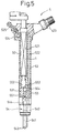
- the injector 5 is applied to a common rail injection system of a Diesel engine as shown in Fig. 5.
- the injector 5 shown in Fig. 5 includes an upper housing 52 accommodating the piezoelectric device 1 as the driving portion and a lower housing 53 fixed to the lower end of the upper housing 52 and forming therein an injection nozzle portion 54.
- the upper housing 52 is substantially circularly cylindrical, and the piezoelectric device 1 is fitted into, and fixed to, a longitudinal hole 521 that is eccentric to a center axis.
- a high-pressure fuel passage 522 is disposed in parallel with, and on the side of, the longitudinal hole 521, and its upper end portion passes through a fuel introduction pipe 523 protruding upward from the upper housing 52, and communicates with an external common rail (not shown).
- the drain passage 524 communicates with a later-appearing three-way valve 551 through a passage that passes through a gap 50 between the longitudinal hole 521 and the driving portion (piezoelectric device) 1 and extends down from this gap 50 inside the upper and lower housings 52 and 53.
- the injection nozzle portion 54 includes a nozzle needle 541 that slides up and down inside a piston body 531 and an injection hole 543 that is opened and closed by the nozzle needle 541 and injects the high-pressure fuel supplied from a fuel reservoir 542 into each cylinder of an engine.
- the fuel reservoir 542 is formed around an intermediate portion of the nozzle needle 541, and the lower end portion of the high-pressure fuel passage 522 opens to this fuel reservoir 542.
- the nozzle needle 541 receives the fuel pressure from the fuel reservoir 542 in the valve opening direction and the fuel pressure from a backpressure chamber 544 so disposed as to face the upper end face in the valve closing direction. When the pressure of the backpressure chamber 544 drops, the nozzle needle 541 lifts, so that the injection hole 543 is opened and the fuel is injected.
- the three-way valve 551 increases and decreases the pressure of the backpressure chamber 544.
- the three-way valve 551 is constituted in such a fashion as to selectively communicate with the backpressure 544 and the high-pressure fuel passage 522 or the drain passage 524.
- the backpressure chamber has a ball-like valve disc that opens and closes a port communicating with the high-pressure fuel passage 522 or the drain passage 524.
- the driving portion 1 described above drives this valve disc through a large diameter piston 552, an oil pressure chamber 553 and a small diameter piston 554 that are disposed below the driving portion 1, respectively.
- the ratio d(0.1Ec)/d(1.2Ec) of the piezoelectric constants is at least 0.43, preferably greater than 0.5. Therefore, the piezoelectric device 1 is excellent in heat resistance and exhibits extremely high durability.
- the piezoelectric device 1 of this embodiment exhibits excellent durability and can be used for a long time when applied to the injector 5.
- piezoelectric devices each having the same structure as that of the piezoelectric device 1 of the first embodiment but having a different composition of the piezoelectric layer are prepared, and the ratios of the piezoelectric constants d(0.1Ec)/d(1.2Ec) are determined respectively.
- the temperature rise due to self-exothermy of each piezoelectric device is measured.
- Table 1 show the measurement values of the ratios of the piezoelectric constants d(0.1Ec)/d(1.2Ec) of the samples.
- the measurement method in this case is the same as that of the first embodiment.
- the temperature of the side surface at the center in the laminating direction is measured while the piezoelectric device is driven at an applied voltage of 0 to 1.5 V/mm and a frequency of 200 Hz.
- the change ratio of displacement of each of the four samples (samples 1 to 4) used in the second embodiment with respect to the frequency of the applied voltage is measured.
- Table 2 shows the change ratio of displacement of each sample with the measurement result of the temperature rise due to self-exothermy of each piezoelectric device.
- a dielectric loss is determined from a P - E hysteresis (charge - voltage hysteresis) of each of the four samples (samples 1 to 4) used in the second embodiment, and the relation between this value and the temperature rise due to self-exothermy is examined.
- the P-E hysteresis of each sample is determined in the following way.
- a measuring jig 6 is prepared as shown in Fig. 9.
- the measuring jig 6 has two guide poles 62 implanted onto a stool 61.
- a bridge 63 is mounted to the guide poles 62, and a pressing portion 64 having a pressing plate 641 is disposed at the center of the bridge 63.
- the piezoelectric device 1 is sandwiched between the pressing plate 641 and the stool 61.
- the pressing plate 641 applies a preset load of 10 MPa in cooperation with a flat-head spring 65 interposed between the pressing plate 641 and the bridge 63.
- a sine wave voltage having a field intensity of 0 to 1.5 kV/mm and a frequency of 100 Hz is applied to each piezoelectric device 1 to determine hystereis as shown in Fig. 10.
- the electric field E (V/mm) is plotted on the abscissa and an integration value P (charge density: C/mm 2 ) is plotted on the ordinate.
- the voltage is gradually increased in the same direction as the polarizing direction and is thereafter decreased gradually so as to plot the trajectory of P.
- S1 The area of a portion encompassed by the resulting hysteresis curves is called "S1" as shown in Fig. 10.
- S2 an area S2 of a triangle encompassed by a line that connects the origin O to the highest point Q, a line that is drawn perpendicularly from the point Q to the abscissa, and the abscissa.
- the dielectric loss can be calculated from these values.
- the dielectric loss (%) can be calculated from S1/S2/(2 ⁇ ) x 100.
- the dielectric loss when the piezoelectric device is actually used can be estimated.
- Table 3 shows the dielectric loss of each sample 1 to 4 obtained in this way together with the temperature rise due to self-exothermy obtained in the same way as in the first embodiment.
- the present invention can acquire its function and effect irrespective of the shape of the piezoelectric device.
- a similar function and effect can be obtained when the piezoelectric device 1 has a barrel-shaped section.
- a piezoelectric device for an injector according to the fifth embodiment of the present invention will be explained with reference to Figs. 14 to 19.
- the piezoelectric device for an injector is the piezoelectric device that is built in the injector 5 and generates the driving force of the injector 5 as shown in Fig. 19.
- the piezoelectric device 1 includes a plurality of piezoelectric layers 11 that expand and contract in accordance with an applied voltage, and internal electrode layers 21 and 22 for supplying the applied voltage, whereby the piezoelectric layers 11 and the internal electrode layers 21 and 22 are alternately laminated.
- the sectional shape crossing at right angles the laminating direction is partly arcuate.
- the piezoelectric device 1 is accommodated in a cylindrical case 4 that constitutes a circular cylindrical accommodation space.
- the piezoelectric device 1 is fabricated in such a fashion that the internal electrode layers 21 and 22 alternately become positive and negative between adjacent pairs of piezoelectric layers as shown in Figs. 14 and 15.
- One 21 of the internal electrode layers is exposed on one 101 of the side surfaces and the other internal electrode layer 22 is exposed on the other side surface 102 as shown in these drawings.
- Side surface electrodes 31 and 32 are formed on the side surfaces 101 and 102 of the piezoelectric device 1 so as to electrically connect the end portions of the internal electrode layers 21 and 22 so exposed.
- the center portion in the laminating direction is a driving portion 111, and portions so arranged as to sandwich the driving portion 111 are buffer portions 112. Further, portions so arranged as to sandwich the buffer portions are dummy portions 113.
- two line portions connect arcuate portions into a barrel-shaped section as shown in Figs. 14 and 15.
- a green sheet method that has been widely employed can be used for producing the piezoelectric device 1 of this embodiment.
- Powders of principal starting materials of the piezoelectric material that is, lead oxide, zirconium oxide, titanium oxide, niobium oxide, strontium carbonate, etc, are weighed by a known method to form a desired composition.
- the composition is prepared so that the lead content becomes by 1 to 2% richer than the stoichiometric ratio of the mixture composition.
- These starting materials are dry mixed by a mixer and are then calcined at 800 to 950°C.
- pure water and a dispersant are added to calcined powder to prepare slurry, and the slurry is wet pulverized by a pearl mill. After the pulverizate is dried and degreased, a solvent, a binder, a plasticizer, a dispersant, etc, are added. A ball mill is employed to mix the slurry. Thereafter, the slurry is vacuum defoamed and its viscosity is adjusted while the slurry is being stirred by using a stirrer inside a vacuum apparatus.
- the slurry is passed through a doctor blade apparatus to form a green sheet having a predetermined thickness.
- the green sheet After recovery, the green sheet is punched out by a press machine or is cut by a cutting machine into rectangles having a predetermined size.
- the green sheet is used in common for the driving portion, the buffer portion and the dummy portion.
- Fig. 16A shows an example of the green sheet after pattern printing. Incidentally, like reference numerals will be used to identify like constituent members for the sake of explanation.
- a barrel-shaped pattern 21 (22) that is a little smaller than the surface of the green sheet 11 is formed on the substantial whole surface of the green sheet 11 that is to serve the piezoelectric layer by use of the Ag/Pd paste described above to form the internal electrode layers 21 (22).
- a non-formation portion 119 of the internal electrode layer 21 (22) is disposed on one of the opposed sides of the surface of the green sheet 11. In other words, the internal electrode layer 21 (22) does not reach one of the end portions of the opposed sides of the green sheet 11 (the portion corresponding to either the side surface 101 or 102 of the piezoelectric device 1), but reaches the other opposed side.
- a predetermined number of green sheets 11 having such an internal electrode layer 21 (22) formed thereon are prepared on the basis of the required specification corresponding to the driving portion 111 and the displacement quantity of the buffer portion 112.
- a predetermined number of green sheets 12 for the buffer portion 112 and for the dummy portion 113, to which the internal electrode layer is not printed, are also prepared.
- Fig. 17 shows a lamination state of the green sheets 11 and 12 and is substantially an exploded view of the piezoelectric device 1.
- each internal electrode layer 21 reaching the side surface 101 of the green sheet 11 on the right side in the drawing and exposed serves as the internal electrode having one of polarity
- each internal electrode layer 22 reaching the side surface 102 on the left side in the drawing and exposed serves as the internal electrode of the other polarity.
- the green sheets 11 having the internal electrode layer 21 (22) are laminated as shown in Fig. 17.
- the green sheets 12 not having the internal electrode layer are sandwiched between pairs of the green sheets 11. Further, in the dummy portions 113, only the green sheets 12 not having the internal electrode layer are laminated.
- degreasing is conducted at 400 to 700°C inside an electric furnace.
- the laminate body is then baked at 900 to 1,200°C.
- the Ag/Pd paste or the Ag paste is applied and baked to the side surface of the laminate body, forming the external electrodes 31 and 32.
- the external electrode 31 is formed at the position at which the internal electrode layer 21 having one of polarity is exposed, to establish electric connection for each internal electrode layer 21.
- the other external electrode 32 is formed at the position at which the internal electrode layer 22 having the other polarity is exposed, to establish electric connection for each internal electrode layer 22.
- the assembly so obtained is thereafter immersed in insulating oil, and a DC voltage is applied across the internal electrode layers 21 and 22 from the external electrodes 31 and 32 to thereby polarize the piezoelectric layer 11 and to obtain the piezoelectric device 1.
- the same green sheet (piezoelectric layer) 12 as the piezoelectric layer 11 used for the driving portion 111 is used as described above to prevent the increase of the number of kinds of production materials and to reduce the production cost.
- the piezoelectric layer 12 of the dummy portion 113 may be made of other materials such as insulating and magnetic materials.
- the matter of importance in the piezoelectric device 1 of this embodiment is that two arcuate portions are disposed as described above so as to increase the proximity with the inner surface of the cylindrical case.
- the side surfaces 101 and 102 parallel to the laminating direction are side surface flat portions having a width of at least 2.5 mm.
- the side surface electrodes 31 and 32 are provided to the side surface flat portions 101 and 102 as described above.
- Electrode take-out portions are bonded to the external electrodes 31 and 32 of the side surface portions 101 and 102 of the piezoelectric device 1, respectively.
- An insulating film 6 having a thickness of 0.002 to 0.5 mm is formed on the entire side surfaces 101 and 102 of the piezoelectric device 1 crossing at right angles the laminating direction (see Fig. 18).
- This embodiment uses silicon resin as the insulating film 6.
- the piezoelectric device 1 is accommodated into the cylindrical case 4.
- the maximum outer diameter R1 of the piezoelectric device 1 inclusive of the insulating member 6 and the inner diameter R2 of the cylindrical case are set so that an R2 - R1 value is not greater than 0.5 mm.
- the injector 5 is applied to a common rail injection system of a Diesel engine as shown in Fig. 19.
- the injector 5 shown in Fig. 19 includes an upper housing 52 accommodating the piezoelectric device 1 as the driving portion and a lower housing 53 fixed to the lower end of the upper housing 52 and forming therein an injection nozzle portion 54.
- the upper housing 52 is substantially circularly cylindrical, and the piezoelectric device 1 is hermetically fitted into, and fixed to, a longitudinal hole 521 that is eccentric to a center axis.
- a high-pressure fuel passage 522 is disposed in parallel with, and on the side of, the longitudinal hole 521, and its upper end portion passes through a fuel introduction pipe 523 protruding upward from the upper housing 52, and communicates with an external common rail (not shown).
- the drain passage 524 communicates with a later-appearing three-way valve 551 through a passage that passes through a gap 50 between the longitudinal hole 521 and the driving portion (piezoelectric device) 1 and extends down from this gap 50 inside the upper and lower housings 52 and 53.
- the injection nozzle portion 54 includes a nozzle needle 541 that slides up and down inside a piston body 531 and an injection hole 543 that is opened and closed by the nozzle needle 541 and injects the high-pressure fuel supplied from a fuel reservoir 542 into each cylinder of an engine.
- the fuel reservoir 542 is formed around an intermediate portion of the nozzle needle 541, and the lower end portion of the high-pressure fuel passage 522 opens to this fuel reservoir 542.
- the nozzle needle 541 receives the fuel pressure from the fuel reservoir 542 in the valve opening direction and the fuel pressure from a backpressure chamber 544 so disposed as to face the upper end face in the valve closing direction. When the pressure of the backpressure chamber 544 drops, the nozzle needle 541 lifts, so that the injection hole 543 is opened and the fuel is injected.
- the three-way valve 551 increases and decreases the pressure of the backpressure chamber 544.
- the three-way valve 551 is constituted in such a fashion as to selectively communicate with the backpressure 544 and the high-pressure fuel passage 522 or the drain passage 524.
- the backpressure chamber 544 has a ball-like valve disc that opens and closes a port communicating with the high-pressure fuel passage 522 or the drain passage 524.
- the driving portion 1 described above drives this valve disc through a large diameter piston 552, an oil pressure chamber 553 and a small diameter piston 554 that are disposed below the driving portion 1, respectively.
- This embodiment uses the piezoelectric device 1 as the driving source in the injector 5 described above.
- the piezoelectric device 1 is constituted in such a fashion that it is built in the circular cylindrical case 4, and at least a part of its sectional shape is arcuate as described above. More concretely, the piezoelectric device 1 in this embodiment has a barrel-shaped sectional shape.
- the piezoelectric device 1 of this embodiment can increase the sectional area when accommodated in the cylindrical case much more than when the sectional shape is rectangular or hexagonal, and the accommodation space can be effectively utilized.
- the side surfaces 101 and 102 for disposing the side electrodes are the side surface flat portions having a width of at least 2.5 mm. Therefore, the side surface electrodes can be disposed without swelling from the circumscribing circle of the piezoelectric device 1.
- the piezoelectric device 1 can occupy a sufficiently large sectional area inside the cylindrical case 4. In consequence, the generation force of the piezoelectric device 1 can be increased.
- the arcuate portions can be brought into an extremely proximate state to the cylindrical case 4 encircling the piezoelectric device 1.
- proximity between the piezoelectric device 1 and the cylindrical case 4 can be increased, and heat transfer can be efficiently achieved from the piezoelectric device to the cylindrical case.
- the piezoelectric device 1 itself generates heat, this heat can be easily radiated from the cylindrical case. Consequently, the temperature rise of the piezoelectric device can be suppressed.
- the piezoelectric device 1 according to this embodiment can exhibit a large generation force and has high heat radiation performance when it is accommodated in the cylindrical case 4.
- an insulating film 6 having a thickness of 0.002 to 0.5 mm is formed on the entire surface crossing at right angles the laminating direction. Therefore, electric insulation of the piezoelectric device 1 can be reliably secured inside the cylindrical case 4.
- the difference of the maximum outer diameter R1 of the piezoelectric device 1 inclusive of the insulating member 6 and the inner diameter R2 of the cylindrical case, that is, R2 - R1 is not greater than 0.5 mm, and they are very proximate to each other. Therefore, heat transfer between them becomes excellent, and a sufficient margin can be secured against the increase of the thermal load resulting from miniaturization of the piezoelectric device 1.
- This embodiment represents an example of a piezoelectric device whose sectional shape is octagonal.
- the piezoelectric device 1 of this embodiment 1 is fabricated by alternately laminating a plurality of piezoelectric layers 11 expanding and contracting in accordance with an applied voltage and a plurality of internal electrode layers 2 for supplying the applied voltage, whereby the sectional shape crossing at right angles the laminating direction is octagonal.
- the production method of this piezoelectric device 1 is the same as that of the first embodiment with the exception that only the sectional shape is different.
- An insulating film 6 having a thickness of 0.002 to 0.5 mm is formed on the surface of the entire side surface of the piezoelectric device 1 in this embodiment, too, as illustrated in Fig. 21.
- the difference of the maximum outer diameter R1 of the piezoelectric device 1 inclusive of the insulating member 6 and the inner diameter R2 of the cylindrical case, that is, R2 - R1, is set to 0.5 mm or below.
- the piezoelectric device 1 according to this embodiment is accommodated in the cylindrical case 4 and its sectional shape is octagonal. Therefore, in comparison with the polygonal shapes having a smaller number of corners than the octagonal shape, such as the rectangular or hexagonal shape, the sectional area of the piezoelectric device 1 can be much more increased and the accommodation space can be more effectively utilized. In consequence, the force generation of the piezoelectric device 1 can be increased, too.
- the sectional shape is octagonal, the angle at each corner is greater than that of other polygonal shapes having a smaller number of corners, and proximity between the piezoelectric device 1 and the cylindrical case 4 encircling the former increases.
- the number of portions having a smaller distance between the piezoelectric device 1 and the cylindrical case 4 increases or, the space decreases, and heat can be more efficiently transferred from the piezoelectric device 1 to the cylindrical case 4. Consequently, when the piezoelectric device 1 generates heat, this heat can be easily radiated from the cylindrical case, and the temperature rise of the piezoelectric device 1 can be suppressed.
- This embodiment can exhibit the function and effect similar to that of the fifth embodiment.
- This embodiment prepares six kinds of piezoelectric devices 1 having the same basic structure as that of the first embodiment but mutually different in only the sectional shape. The temperature rise due to self-exothermy is measured, and durability estimated from the measurement result is evaluated.
- the sectional shapes of the piezoelectric devices are barrel-shape and circles based on a square, a regular hexagon, a square with arcuate corners (R-chamfering of a square), an octagon and a regular hexagonal, respectively.
- Each sectional area ratio represents the value with the value of the circle as 1.0.
- the polygon of the section need not be a regular polygon but may be an arbitrary shape.
- each piezoelectric device is driven at an applied voltage of 0 to 1.5 kV/mm and a frequency of 200 Hz, and the temperature of the side surface at the center in the laminating direction is measured.
- Table 4 shows the result. It can be appreciated from Table 4 that in the samples 3 to 6 in which the sectional shape is a polygon greater than the octagon or at least a part of the section is arcuate, the temperature rise due to self-exothermy can be suppressed to 100°C or below. In contrast, in the samples whose sectional shapes are square and hexagonal, the temperature rise exceeding 100°C can be observed. It can be estimated from the temperature rise, etc, that when a durability test for operating 1 x 10 9 times the piezoelectric device is conducted, the samples 3 to 6 pass the test ( ⁇ ) and exhibit high durability, whereas the samples 1 and 2 cannot pass the test (X) and the improvement in durability cannot be observed.
- sample sectional shape sectional area ratio temperature rise (C) durability 1 square 0.64 112 X 2 hexagon 0.83 108 X 3 square R-chamfering 0.92 92 ⁇ 4 octagon 0.90 95 ⁇ 5 barrel (based on hexagon) 0.94 90 ⁇ 6 circle 1.00 88 ⁇
- the result of the seventh embodiment is examined in relation with the proximity ratio.
- Table 5 shows the proximity ratio of each sample.
- This proximity ratio is expressed by (B/A) x 100 (%) where A is the length of the entire circumference of the circumscribed circle of the piezoelectric device 1 and B is the total length of the circumferential portions that have a distance of not greater than 0.2 mm from the circumscribed circle.
- Fig. 23 shows the case where the piezoelectric device 1 has an octagonal shape by way of example.
- the portions having a distance D of not greater than 0.2 mm between the circumscribed circle C and the piezoelectric device 1 are represented by sold line portions b 1 to b 8 in the circumscribed circle, and the sum of the length of these arcs is B.
- the length A of the entire circumference of the circumscribed circle C is 2 ⁇ r as is well known.
- This embodiment concretely represents the electrode take-out portion to the piezoelectric device 1 in the fifth embodiment.
- the most ordinary method directly disposes the electrode take-out portions to the external electrodes 31 and 32 formed on the side surfaces 101 and 102 of the piezoelectric device 1.
- This embodiment particularly disposes the electrode take-out portions 315 and 316 electrically connected to the internal electrode layers 21 and 22 at the distal end face and the rear end face of the piezoelectric device 1 in the laminating direction, respectively.
- the external electrode 31 disposed on the side surface 101 on the right side and the upper electrode take-out portion 315 are brought into mutual contact and are electrically connected.
- the external electrode 32 disposed on the side surface on the left side and the lower electrode take-out portion 325 are brought into mutual contact and are electrically connected.
- each electrode take-out portion 315, 325 is smaller than the area of each of the distal and rear end faces of the piezoelectric device 1, and the electrode take-out portion 315, 325 and the corresponding internal electrode layer 21, 22 are electrically connected with one another through a through-hole 319, 329 formed inside the piezoelectric device 1.
- the electrode take-out portions 315 and 325 are disposed on the distal end face and the rear end face of the piezoelectric device 1 in the laminating direction.
- the overall structure of the piezoelectric device 1 can be simplified and the production cost can be lowered.
- This embodiment concretely represents another example of the electrode take-out portions to the piezoelectric device in the first embodiment.
- two electrode take-out portions 315 and 325 electrically connected to the internal electrode layers 21 and 22 are disposed on either one of the distal end face and the rear end face of the piezoelectric device 1 in the laminating direction (the upper end face in the drawings).
- two electrode take-out portions 315 and 325 are disposed in the spaced-apart relation with each other on the distal end face of the piezoelectric device 1 in the laminating direction (the upper end face in the drawings).
- the external electrode 31 disposed on the side surface 101 of the piezoelectric device 1 on the right side and the upper electrode take-out portion 315 on the right side are brought into mutual contact and are electrically connected.
- the external electrode 32 disposed on the side surface 102 on the left side and the upper electrode take-out portion 325 on the left side are brought into mutual contact and are electrically connected.
- two electrode take-out portions 315 and 325 are disposed in a double circle.
- the electrode take-out portion 315 and the internal electrode layer 21 are electrically connected with each other through a through-hole 319, and the electrode take-out portion 325 and the internal electrode layer 22 are electrically connected with each other through a through-hole 329.
- the shape of the electrode take-out portions 315 and 325 shown in Figs. 26A and 26B is changed.
- one 315 of the electrode take-out portion has a C shape and is so disposed as to encompass the other electrode take-out portion 325.
- the rest of the constructions are the same as those of Figs. 26A and 26B.
- two electrode take-out portions 315 and 325 are disposed on either one of the distal end face and the rear end face of the piezoelectric device 1 in the laminating direction. In this case, too, the overall structure of the piezoelectric device 1 can be simplified and the production cost can be lowered.
- the piezoelectric device 1 in the fifth embodiment is disposed inside the injector 5 without being sealed into the circularly cylindrical case 4.
- the housing 52 itself of the injector 5 has a cylindrical accommodation space as shown in Fig. 29.
- the fuel passage is disposed at a portion separate from the cylindrical accommodation space.
- the rest of the basic structures are the same as those of the injector 5 of the first embodiment. In this case, too, the function and effect substantially similar to that of the fifth embodiment can be obtained.
- the piezoelectric device so fabricated has high durability and can be used for a long time.
- the piezoelectric device 1 is fabricated by alternately laminating a plurality of piezoelectric layers expanding and contracting in proportion to an applied voltage and a plurality of internal electrode layers for supplying the applied voltage, and the sectional shape of the piezoelectric device crossing at right angles the laminating direction is partially or wholly arcuate.
- the piezoelectric device 1 is accommodated in a cylindrical accommodation space.
Landscapes
- Engineering & Computer Science (AREA)
- Chemical & Material Sciences (AREA)
- Combustion & Propulsion (AREA)
- Mechanical Engineering (AREA)
- General Engineering & Computer Science (AREA)
- Physics & Mathematics (AREA)
- Fluid Mechanics (AREA)
- Fuel-Injection Apparatus (AREA)
Abstract
Description
| sample | piezoelectric constant d(0.1Ec/d(1.2Ec) | temperature rise (C) | durability |
| 1 | 0.40 | 118 | X |
| 2 | 0.43 | 110 | X |
| 3 | 0.50 | 98 | ○ |
| 4 | 0.65 | 80 | ○ |
| sample | displacement change ratio (%) | temperature rise (C) | durability |
| 1 | 12 | 118 | X |
| 2 | 9 | 110 | X |
| 3 | 7 | 98 | ○ |
| 4 | 3 | 80 | ○ |
| sample | dielectric loss (%) | temperature rise (°C) | durability |
| 1 | 10 | 118 | X |
| 2 | 8 | 110 | X |
| 3 | 7 | 98 | ○ |
| 4 | 2 | 80 | ○ |
| sample | sectional shape | sectional area ratio | temperature rise (C) | durability |
| 1 | square | 0.64 | 112 | X |
| 2 | hexagon | 0.83 | 108 | X |
| 3 | square R-chamfering | 0.92 | 92 | ○ |
| 4 | octagon | 0.90 | 95 | ○ |
| 5 | barrel (based on hexagon) | 0.94 | 90 | ○ |
| 6 | circle | 1.00 | 88 | ○ |
| sample | sectional shape | proximity ratio | temperature rise (°C) | durability |
| 1 | square | 10% | 112 | X |
| 2 | hexagonal | 17% | 108 | X |
| 3 | square R-chamfering | 32% | 92 | ○ |
| 4 | octagonal | 36% | 95 | ○ |
| 5 | barrel-shaped (based on hexagon) | 45% | 90 | ○ |
| 6 | circle | 100% | 88 | ○ |
Claims (30)
- A piezoelectric device for an injector, built into an injector and generating driving force of said injector, characterized in that:said piezoelectric device is fabricated by alternately laminating a plurality of piezoelectric layers generating displacement in proportion to an applied voltage and a plurality of internal electrode layers for supplying the applied voltage; andin said piezoelectric device, a relation d(0.1Ec)/d(1.2Ec) > 0.43 is established, where Ec is coercive electric field which causes the changing of polarizing direction, between an apparent piezoelectric constant d(1.2Ec) calculated from static elongation when an electric field of 1.2 Ec is applied to said piezoelectric device in the same direction as a polarizing direction while a preset load of 500 N is applied to said piezoelectric device, and an apparent piezoelectric constant d(0.1Ec) calculated from static elongation when an electric field of 0.1 Ec is applied to said piezoelectric device in the same direction as the polarizing direction.
- A piezoelectric device for an injector according to claim 1, wherein a relation d(0.1Ec)/d(1.2Ec) ≧ 0.5 is established between said piezoelectric constant d(1.2Ec) and said piezoelectric constant d(0.1Ec).
- A piezoelectric device for an injector, built into an injector and generating driving force of said injector, characterized in that:said piezoelectric device is fabricated by alternately laminating a plurality of piezoelectric layers generating displacement in proportion to an applied voltage and a plurality of internal electrode layers for supplying the applied voltage; andsaid piezoelectric device has a change ratio of displacement of 9% or below when a frequency of the applied voltage is changed from 1 Hz to 200 Hz under the state where an AC voltage is applied so that an electric field intensity of 0 to 1.5 kV/mm is generated by a sine wave while a preset load of 500 N is applied to said piezoelectric device.
- A piezoelectric device for an injector according to claim 1, wherein said change ratio of displacement is 7% or below.
- A piezoelectric device for an injector, built in an injector and generating driving force of said injector, characterized in that:said piezoelectric device is fabricated by alternately laminating a plurality of piezoelectric layers generating displacement in proportion to an applied voltage and a plurality of internal electrode layers for supplying the applied voltage; andin said piezoelectric device, displacement increases with the rise of temperature within the range of -40°C to 150°C.
- A piezoelectric device for an injector according to claim 5, wherein said change ratio of displacement is 5 to 40% within the range of temperature of -40°C to 150°C.
- A piezoelectric device for an injector, built in an injector and generating driving force of said injector, characterized in that:said piezoelectric device is fabricated by alternately laminating a plurality of piezoelectric layers generating displacement in proportion to an applied voltage and a plurality of internal electrode layers for supplying the applied voltage; andsaid piezoelectric device has a dielectric loss of 8% or below calculated from a P-E hysteresis.
- A piezoelectric device for an injector according to claim 7, wherein said dielectric loss is 7% or below.
- A piezoelectric device for an injector built in an injector and generating driving force of said injector, characterized in that:said piezoelectric device is fabricated by alternately laminating a plurality of piezoelectric layers expanding and contracting in proportion to an applied voltage and a plurality of internal electrode layers for supplying the applied voltage;the sectional shape of said piezoelectric device crossing at right angles the laminating direction is an octagon or a polygon with a larger number of sides than octagon; andsaid piezoelectric device is accommodated in a cylindrical accommodation space.
- A piezoelectric device for an injector according to claim 9, wherein a proximity ratio expressed by (B/A) x 100 (%), where A is a length of the whole circumference of a circumscribed circle of said piezoelectric device and B is the sum of length of circumferential portions having a distance of 0.2 mm or below between said circumscribed circle and said piezoelectric device, is larger than 17%.
- A piezoelectric device for an injector according to claim 9, wherein a proximity ratio expressed by (B/A) x 100 (%), where A is a length of the whole circumference of a circumscribed circle of said piezoelectric device and B is the sum of length of circumferential portions having a distance of 0.2 mm or below between said circumscribed circle and said piezoelectric device, is 32% or more.
- A piezoelectric device for an injector according to claim 9, wherein at least two side surface flat portions having a width of 2.5 mm or more are disposed on a side surface parallel to said laminating direction.
- A piezoelectric device for an injector according to claim 9, wherein an insulating film having a thickness of 0.002 to 0.5 mm is formed at least on the surface of a side surface parallel to the laminating direction.
- A piezoelectric device for an injector according to claim 13, wherein a value R2 - R1, where R1 is a maximum outer diameter of said piezoelectric device inclusive of said insulating member and R2 is an inner diameter of said circular cylindrical accommodation space, is 0.5 mm or below.
- A piezoelectric device for an injector according to claim 13, wherein said insulating film is made of any of a silicone resin, a polyimide resin, an epoxy resin and a fluorocarbon resin.
- A piezoelectric device for an injector according to claim 9, wherein electrode take-out portions electrically connected to said internal electrode layers are disposed on a distal end face and a rear end face of said piezoelectric device in the laminating direction, respectively.
- A piezoelectric device for an injector according to claim 9, wherein two electrode take-out portions electrically connected to said internal electrode layer are disposed on either one of a distal end face and a rear end face of said piezoelectric device in the laminating direction.
- A piezoelectric device for an injector according to claim 16, wherein at least one of said electrode take-out portions is electrically connected to at least one of said internal electrode layers through a through-hole formed in said piezoelectric layer.
- A piezoelectric device for an injector according to claim 16, wherein at least one of said electrode take-out portions is electrically connected to a side surface disposed on said side surface of said piezoelectric device.
- A piezoelectric device for an injector built in an injector and generating driving force of said injector, characterized in that:said piezoelectric device is fabricated by alternately laminating a plurality of piezoelectric layers expanding and contracting in proportion to an applied voltage and a plurality of internal electrode layers for supplying the applied voltage;at least a part or the whole of the sectional shape of said piezoelectric device crossing at right angles the laminating direction is arcuate; andsaid piezoelectric device is accommodated in a circular cylindrical accommodation space.
- A piezoelectric device for an injector according to claim 20, wherein a proximity ratio expressed by (B/A) x 100 (%), where A is a length of the whole circumference of a circumscribed circle of said piezoelectric device and B is the sum of length of circumferential portions having a distance of 0.2 mm or below between said circumscribed circle and said piezoelectric device, is larger than 17%.
- A piezoelectric device for an injector according to claim 20, wherein a proximity ratio expressed by (B/A) x 100 (%), where A is a length of the whole circumference of a circumscribed circle of said piezoelectric device and B is the sum of length of circumferential portions having a distance of 0.2 mm or below between said circumscribed circle and said piezoelectric device, is 32% or more.
- A piezoelectric device for an injector according to claim 20, wherein at least two side surface flat portions having a width of 2.5 mm or more are disposed on the side surface parallel to the laminating direction.
- A piezoelectric device for an injector according to claim 20, wherein an insulating film having a thickness of 0.002 to 0.5 mm is formed on at least the surface of the side surface parallel to the laminating direction of said piezoelectric device.
- A piezoelectric device for an injector according to claim 24, wherein a value R2 - R1, where R1 is a maximum outer diameter of said piezoelectric device inclusive of said insulating member and R2 is an inner diameter of said cylindrical accommodation space, is 0.5 mm or below.
- A piezoelectric device for an injector according to claim 24, wherein said insulating film is made of any of a silicone resin, a polyimide resin, an epoxy resin and a fluorocarbon resin.
- A piezoelectric device for an injector according to claim 20, wherein electrode take-out portions electrically connected to said internal electrode layers are disposed on a distal end face and a rear end face of said piezoelectric device in the laminating direction, respectively.
- A piezoelectric device for an injector according to claim 20, wherein two electrode take-out portions electrically connected to said internal electrode layer are disposed on either one of a distal end face and a rear end face of said piezoelectric device in the laminating direction.
- A piezoelectric device for an injector according to claim 27, wherein at least one of said electrode take-out portions is electrically connected to at least one of said internal electrode layers through a through-hole formed in said piezoelectric layer.
- A piezoelectric device for an injector according to claim 27, wherein at least one of said electrode take-out portions is electrically connected to a side surface disposed on said side surface of said piezoelectric device.
Applications Claiming Priority (8)
| Application Number | Priority Date | Filing Date | Title |
|---|---|---|---|
| JP2000163235 | 2000-05-31 | ||
| JP2000163235 | 2000-05-31 | ||
| JP2000163233 | 2000-05-31 | ||
| JP2000163233 | 2000-05-31 | ||
| JP2001130167A JP2002054525A (en) | 2000-05-31 | 2001-04-26 | Piezoelectric element for injector |
| JP2001130167 | 2001-04-26 | ||
| JP2001130169 | 2001-04-26 | ||
| JP2001130169A JP2002054527A (en) | 2000-05-31 | 2001-04-26 | Piezoelectric element for injector |
Publications (3)
| Publication Number | Publication Date |
|---|---|
| EP1160885A2 true EP1160885A2 (en) | 2001-12-05 |
| EP1160885A3 EP1160885A3 (en) | 2006-08-02 |
| EP1160885B1 EP1160885B1 (en) | 2010-08-18 |
Family
ID=27481333
Family Applications (1)
| Application Number | Title | Priority Date | Filing Date |
|---|---|---|---|
| EP01113169A Expired - Lifetime EP1160885B1 (en) | 2000-05-31 | 2001-05-30 | Piezoelectric device for injector |
Country Status (3)
| Country | Link |
|---|---|
| US (3) | US6787975B2 (en) |
| EP (1) | EP1160885B1 (en) |
| DE (1) | DE60142818D1 (en) |
Cited By (3)
| Publication number | Priority date | Publication date | Assignee | Title |
|---|---|---|---|---|
| FR2842354A1 (en) * | 2002-07-12 | 2004-01-16 | Bosch Gmbh Robert | PIEZOELECTRIC COMPONENT |
| EP1798782A1 (en) * | 2005-12-13 | 2007-06-20 | Siemens Aktiengesellschaft | Piezoelectric actuator and manufacturing method of a piezostack |
| WO2011020844A1 (en) * | 2009-08-20 | 2011-02-24 | Continental Automotive Gmbh | Optimized actuator unit for an injector valve |
Families Citing this family (15)
| Publication number | Priority date | Publication date | Assignee | Title |
|---|---|---|---|---|
| DE19928102B4 (en) * | 1999-06-19 | 2005-06-02 | Daimlerchrysler Ag | Vehicle with a drive internal combustion engine and with a fuel cell system for supplying electrical consumers of the vehicle and method for operating such a vehicle |
| DE60142818D1 (en) * | 2000-05-31 | 2010-09-30 | Denso Corp | Piezoelectric component for an injection device |
| DE10217097A1 (en) * | 2001-04-18 | 2002-11-21 | Denso Corp | Process for the production of a ceramic laminate |
| DE10237588A1 (en) * | 2002-08-16 | 2004-02-26 | Robert Bosch Gmbh | Piezoelectric actuator e.g. for operating a valve, has internal electrodes between piezo layers, rounded at corners formed by cut edges |
| DE10260854A1 (en) * | 2002-12-23 | 2004-07-08 | Robert Bosch Gmbh | piezo actuator |
| JP4876467B2 (en) * | 2004-12-06 | 2012-02-15 | 株式会社デンソー | Multilayer piezoelectric element |
| DE112005001022B4 (en) * | 2005-01-06 | 2014-08-21 | Murata Manufacturing Co., Ltd. | Method for producing a piezoelectric actuator and piezoelectric actuator |
| EP1868253B1 (en) * | 2005-02-03 | 2008-11-19 | Delphi Technologies, Inc. | Piezoelectric actuator |
| JP2006303443A (en) * | 2005-03-24 | 2006-11-02 | Ngk Spark Plug Co Ltd | Piezoelectric element, manufacturing method of multilayer piezoelectric element and fuel injector using the same |
| WO2007012484A1 (en) * | 2005-07-26 | 2007-02-01 | Siemens Aktiengesellschaft | Method for producing a monolithic piezo actuator with stack elements, monilithic piezo actuator with stack elements, and use of the piezo actuator |
| GB0602955D0 (en) * | 2006-02-14 | 2006-03-29 | Delphi Tech Inc | Piezoelectric actuator |
| DE102007015457B4 (en) * | 2007-03-30 | 2009-07-09 | Siemens Ag | Piezoelectric device with security layer, process for its production and use |
| JP2009113316A (en) * | 2007-11-06 | 2009-05-28 | Fujifilm Corp | Method for driving piezoelectric actuator and liquid ejection apparatus |
| JP2010232806A (en) * | 2009-03-26 | 2010-10-14 | Seiko Epson Corp | Piezoelectric resonator, piezoelectric oscillator, electronic device and method for manufacturing piezoelectric resonator |
| DE102014112207A1 (en) | 2014-08-26 | 2016-03-03 | Epcos Ag | Process for the production of ceramic multilayer components and ceramic multilayer component |
Citations (3)
| Publication number | Priority date | Publication date | Assignee | Title |
|---|---|---|---|---|
| US4803393A (en) | 1986-07-31 | 1989-02-07 | Toyota Jidosha Kabushiki Kaisha | Piezoelectric actuator |
| EP0371469A2 (en) | 1988-11-30 | 1990-06-06 | Toyota Jidosha Kabushiki Kaisha | Apparatus for driving piezoelectric element for closing and opening valve member |
| JPH11229993A (en) | 1997-12-06 | 1999-08-24 | Lucas Ind Plc | Fuel injection device |
Family Cites Families (47)
| Publication number | Priority date | Publication date | Assignee | Title |
|---|---|---|---|---|
| US3418980A (en) * | 1965-09-01 | 1968-12-31 | Physics Internat Company | Fuel injector-ignitor system for internal combustion engines |
| US4675123A (en) * | 1979-01-17 | 1987-06-23 | Ngk Spark Plug Co., Ltd. | Piezoelectric composite material |
| JPS57136859U (en) * | 1981-02-18 | 1982-08-26 | ||
| NL8105502A (en) * | 1981-12-08 | 1983-07-01 | Philips Nv | METHOD FOR MANUFACTURING A PIEZO ELECTRICAL DEVICE AND A DEVICE MANUFACTURED BY THIS METHOD |
| JPS60104762A (en) * | 1983-11-10 | 1985-06-10 | Nippon Soken Inc | Electro-distorsion actuator and fuel injection valve |
| CA1265343A (en) * | 1984-05-07 | 1990-02-06 | Edward Earl Judge Jr. | Microfinishing apparatus and method |
| JPS62107265A (en) * | 1985-11-02 | 1987-05-18 | Nippon Soken Inc | Electrostriction type oil pressure control valve |
| JPS62199076A (en) * | 1986-02-27 | 1987-09-02 | Fuji Elelctrochem Co Ltd | Manufacture of laminated type piezoelectric element |
| JPS6355986A (en) * | 1986-08-26 | 1988-03-10 | Nec Corp | Manufacture of electrostriction effect element |
| US4803763A (en) * | 1986-08-28 | 1989-02-14 | Nippon Soken, Inc. | Method of making a laminated piezoelectric transducer |
| JPS63207185A (en) * | 1987-02-23 | 1988-08-26 | Toyota Motor Corp | Piezoelectric actuator |
| JPS63213381A (en) * | 1987-02-28 | 1988-09-06 | Nec Corp | Laminated ceramic actuator element |
| US5092360A (en) * | 1989-11-14 | 1992-03-03 | Hitachi Metals, Ltd. | Flow rated control valve using a high-temperature stacked-type displacement device |
| JPH03285374A (en) * | 1990-04-02 | 1991-12-16 | Ube Ind Ltd | Piezoelectric bimorph element and driving method therefor |
| JPH0491664A (en) * | 1990-08-07 | 1992-03-25 | Brother Ind Ltd | Laminated vertical effect piezoelectric element |
| US5148077A (en) * | 1990-09-28 | 1992-09-15 | Caterpillar Inc. | Coating surrounding a piezoelectric solid state motor stack |
| JPH04179286A (en) * | 1990-11-14 | 1992-06-25 | Nec Corp | Multilayered piezoelectric actuator |
| JPH04340778A (en) * | 1991-01-30 | 1992-11-27 | Nec Corp | Laminated piezoelectric actuator element |
| JPH05218789A (en) * | 1992-02-05 | 1993-08-27 | Murata Mfg Co Ltd | Piezoelectric resonator |
| DE4228974C2 (en) * | 1992-08-31 | 1999-04-15 | Diehl Stiftung & Co | Piezoelectric actuator |
| JPH0779025A (en) * | 1993-06-18 | 1995-03-20 | Murata Mfg Co Ltd | Connection structure of inner electrode and outer electrode of laminated piezoelectric device |
| JP3114434B2 (en) * | 1993-06-30 | 2000-12-04 | ブラザー工業株式会社 | Driving method of piezoelectric actuator |
| US5645753A (en) | 1994-05-19 | 1997-07-08 | Kyocera Corporation | Piezo-electric ceramic composition |
| JPH08167746A (en) * | 1994-12-14 | 1996-06-25 | Kyocera Corp | Layered piezoelectric actuator |
| JP3198906B2 (en) * | 1995-12-20 | 2001-08-13 | 株式会社村田製作所 | Piezoelectric porcelain composition |
| DE19615695C1 (en) * | 1996-04-19 | 1997-07-03 | Siemens Ag | Monolithic multilayer piezo-actuator production |
| EP0810676B1 (en) * | 1996-05-27 | 2002-08-28 | Ngk Insulators, Ltd. | Piezoelectric film-type element |
| DE19648545B4 (en) | 1996-11-25 | 2009-05-07 | Ceramtec Ag | Monolithic multilayer actuator with external electrodes |
| US5878859A (en) * | 1997-05-09 | 1999-03-09 | Lear Corporation | Manual vehicle seat adjuster with quick release clutch |
| US6465934B1 (en) * | 1997-09-08 | 2002-10-15 | Ngk Insulators, Ltd. | Piezoelectric/electrostrictive device |
| DE19827287A1 (en) * | 1998-06-19 | 1999-12-23 | Bosch Gmbh Robert | Fuel injection valve-pressure sensor combination for fuel injection system |
| JP3319393B2 (en) * | 1998-06-26 | 2002-08-26 | 株式会社村田製作所 | Ladder type piezoelectric filter |
| JP2000040844A (en) * | 1998-07-23 | 2000-02-08 | Tokin Corp | Piezoelectric transformer and driving method therefor |
| DE19857247C1 (en) * | 1998-12-11 | 2000-01-27 | Bosch Gmbh Robert | Piezoelectric actuator for actuating control or injection valves in motor vehicle internal combustion engines |
| DE19905413A1 (en) * | 1999-02-10 | 2000-08-24 | Bosch Gmbh Robert | Injector with piezo multilayer actuator for injection systems |
| CN1138287C (en) * | 1999-06-01 | 2004-02-11 | 李竑一 | Vabriting film extended multi-output composite structured piezoelectric transformer |
| GB9919661D0 (en) * | 1999-08-20 | 1999-10-20 | Lucas Industries Ltd | Actuator housing |
| DE19941044A1 (en) * | 1999-08-28 | 2001-03-22 | Bosch Gmbh Robert | Piezoelectric ceramic body |
| JP2001160636A (en) * | 1999-09-20 | 2001-06-12 | Denso Corp | Piezoelectric element |
| DE60142818D1 (en) * | 2000-05-31 | 2010-09-30 | Denso Corp | Piezoelectric component for an injection device |
| JP2002054525A (en) * | 2000-05-31 | 2002-02-20 | Denso Corp | Piezoelectric element for injector |
| JP2002054526A (en) * | 2000-05-31 | 2002-02-20 | Denso Corp | Piezoelectric element for injector |
| JP4158338B2 (en) * | 2000-06-06 | 2008-10-01 | 株式会社デンソー | Piezoelectric element for injector |
| JP4356268B2 (en) * | 2000-06-26 | 2009-11-04 | 株式会社デンソー | Fuel injection device |
| JP2002203999A (en) * | 2000-11-06 | 2002-07-19 | Denso Corp | Laminated type piezoelectric-substance element and the manufacturing method thereof |
| JP2002203997A (en) * | 2000-12-28 | 2002-07-19 | Denso Corp | Piezoelectric actuator |
| DE10225704A1 (en) * | 2001-06-11 | 2003-01-23 | Denso Corp | Piezoelectric actuator and method for driving it |
-
2001
- 2001-05-30 DE DE60142818T patent/DE60142818D1/en not_active Expired - Lifetime
- 2001-05-30 EP EP01113169A patent/EP1160885B1/en not_active Expired - Lifetime
- 2001-05-30 US US09/866,677 patent/US6787975B2/en not_active Expired - Fee Related
-
2003
- 2003-12-10 US US10/730,904 patent/US6873089B2/en not_active Expired - Fee Related
-
2004
- 2004-10-07 US US10/959,054 patent/US7067960B2/en not_active Expired - Fee Related
Patent Citations (3)
| Publication number | Priority date | Publication date | Assignee | Title |
|---|---|---|---|---|
| US4803393A (en) | 1986-07-31 | 1989-02-07 | Toyota Jidosha Kabushiki Kaisha | Piezoelectric actuator |
| EP0371469A2 (en) | 1988-11-30 | 1990-06-06 | Toyota Jidosha Kabushiki Kaisha | Apparatus for driving piezoelectric element for closing and opening valve member |
| JPH11229993A (en) | 1997-12-06 | 1999-08-24 | Lucas Ind Plc | Fuel injection device |
Cited By (4)
| Publication number | Priority date | Publication date | Assignee | Title |
|---|---|---|---|---|
| FR2842354A1 (en) * | 2002-07-12 | 2004-01-16 | Bosch Gmbh Robert | PIEZOELECTRIC COMPONENT |
| EP1798782A1 (en) * | 2005-12-13 | 2007-06-20 | Siemens Aktiengesellschaft | Piezoelectric actuator and manufacturing method of a piezostack |
| WO2007068569A1 (en) * | 2005-12-13 | 2007-06-21 | Siemens Aktiengesellschaft | Piezo actuator and method for the production of a piezo stack |
| WO2011020844A1 (en) * | 2009-08-20 | 2011-02-24 | Continental Automotive Gmbh | Optimized actuator unit for an injector valve |
Also Published As
| Publication number | Publication date |
|---|---|
| US6787975B2 (en) | 2004-09-07 |
| US20050046310A1 (en) | 2005-03-03 |
| EP1160885B1 (en) | 2010-08-18 |
| US6873089B2 (en) | 2005-03-29 |
| US7067960B2 (en) | 2006-06-27 |
| US20020005680A1 (en) | 2002-01-17 |
| EP1160885A3 (en) | 2006-08-02 |
| DE60142818D1 (en) | 2010-09-30 |
| US20040113527A1 (en) | 2004-06-17 |
Similar Documents
| Publication | Publication Date | Title |
|---|---|---|
| US6787975B2 (en) | Piezoelectric device for injector | |
| US7061162B2 (en) | Laminated piezoelectric element | |
| US6874475B2 (en) | Structure of fuel injector using piezoelectric actuator | |
| US6663015B2 (en) | Piezoelectric device for injector | |
| EP1160886B1 (en) | Piezoelectric element for injector | |
| US6731048B2 (en) | Piezoelectric actuator with insulating member separate from piezoelectric device | |
| US20100156250A1 (en) | Multi-Layer Piezoelectric Element and Method for Manufacturing the Same | |
| JP2002203998A (en) | Piezoelectric-substance element and the manufacturing method thereof | |
| WO2008072767A1 (en) | Laminated piezoelectric element, jetting device provided with the laminated piezoelectric element, and fuel jetting system and | |
| US6664715B2 (en) | Piezoelectric actuator and method for driving the same | |
| JP2003017768A (en) | Stacked piezoelectric element and jet device | |
| JP4325161B2 (en) | Multilayer piezoelectric element, method of manufacturing the same, and injector | |
| JP4048967B2 (en) | Piezoelectric actuator and fuel injection device for internal combustion engine | |
| JP2002054525A (en) | Piezoelectric element for injector | |
| EP2889926B1 (en) | Laminated piezoelectric element, piezoelectric actuator provided with same, injection apparatus, and fuel injection system | |
| JP3879591B2 (en) | Piezoelectric actuator and driving method thereof | |
| JP2001313428A (en) | Laminated type piezoelectric actuator and injection device | |
| JP2002054527A (en) | Piezoelectric element for injector | |
| JP2004319966A (en) | Piezoelectric actuator and piezoelectric ceramic | |
| JP2008277855A (en) | Laminated piezoelectric element, manufacturing method therefor, and injector | |
| JPS61268084A (en) | Electrostrictive actuator device and fuel injector for diesel engine using said device | |
| JP2012146999A (en) | Laminated piezoelectric element and injector using the same |
Legal Events
| Date | Code | Title | Description |
|---|---|---|---|
| PUAI | Public reference made under article 153(3) epc to a published international application that has entered the european phase |
Free format text: ORIGINAL CODE: 0009012 |
|
| AK | Designated contracting states |
Kind code of ref document: A2 Designated state(s): AT BE CH CY DE DK ES FI FR GB GR IE IT LI LU MC NL PT SE TR |
|
| AX | Request for extension of the european patent |
Free format text: AL;LT;LV;MK;RO;SI |
|
| 17P | Request for examination filed |
Effective date: 20050919 |
|
| PUAL | Search report despatched |
Free format text: ORIGINAL CODE: 0009013 |
|
| AK | Designated contracting states |
Kind code of ref document: A3 Designated state(s): AT BE CH CY DE DK ES FI FR GB GR IE IT LI LU MC NL PT SE TR |
|
| AX | Request for extension of the european patent |
Extension state: AL LT LV MK RO SI |
|
| AKX | Designation fees paid |
Designated state(s): DE FR |
|
| 17Q | First examination report despatched |
Effective date: 20070319 |
|
| GRAP | Despatch of communication of intention to grant a patent |
Free format text: ORIGINAL CODE: EPIDOSNIGR1 |
|
| GRAS | Grant fee paid |
Free format text: ORIGINAL CODE: EPIDOSNIGR3 |
|
| GRAA | (expected) grant |
Free format text: ORIGINAL CODE: 0009210 |
|
| AK | Designated contracting states |
Kind code of ref document: B1 Designated state(s): DE FR |
|
| REF | Corresponds to: |
Ref document number: 60142818 Country of ref document: DE Date of ref document: 20100930 Kind code of ref document: P |
|
| PLBE | No opposition filed within time limit |
Free format text: ORIGINAL CODE: 0009261 |
|
| STAA | Information on the status of an ep patent application or granted ep patent |
Free format text: STATUS: NO OPPOSITION FILED WITHIN TIME LIMIT |
|
| 26N | No opposition filed |
Effective date: 20110519 |
|
| REG | Reference to a national code |
Ref country code: DE Ref legal event code: R084 Ref document number: 60142818 Country of ref document: DE Effective date: 20110622 Ref country code: DE Ref legal event code: R084 Ref document number: 60142818 Country of ref document: DE Effective date: 20110614 |
|
| REG | Reference to a national code |
Ref country code: DE Ref legal event code: R097 Ref document number: 60142818 Country of ref document: DE Effective date: 20110519 |
|
| REG | Reference to a national code |
Ref country code: FR Ref legal event code: PLFP Year of fee payment: 15 |
|
| REG | Reference to a national code |
Ref country code: FR Ref legal event code: PLFP Year of fee payment: 16 |
|
| REG | Reference to a national code |
Ref country code: FR Ref legal event code: PLFP Year of fee payment: 17 |
|
| PGFP | Annual fee paid to national office [announced via postgrant information from national office to epo] |
Ref country code: FR Payment date: 20170523 Year of fee payment: 17 Ref country code: DE Payment date: 20170523 Year of fee payment: 17 |
|
| REG | Reference to a national code |
Ref country code: DE Ref legal event code: R119 Ref document number: 60142818 Country of ref document: DE |
|
| PG25 | Lapsed in a contracting state [announced via postgrant information from national office to epo] |
Ref country code: DE Free format text: LAPSE BECAUSE OF NON-PAYMENT OF DUE FEES Effective date: 20181201 Ref country code: FR Free format text: LAPSE BECAUSE OF NON-PAYMENT OF DUE FEES Effective date: 20180531 |