EP1160876A2 - Reconfigurable solar module array - Google Patents
Reconfigurable solar module array Download PDFInfo
- Publication number
- EP1160876A2 EP1160876A2 EP01109720A EP01109720A EP1160876A2 EP 1160876 A2 EP1160876 A2 EP 1160876A2 EP 01109720 A EP01109720 A EP 01109720A EP 01109720 A EP01109720 A EP 01109720A EP 1160876 A2 EP1160876 A2 EP 1160876A2
- Authority
- EP
- European Patent Office
- Prior art keywords
- solar
- solar cell
- integrated circuit
- solar panel
- module
- Prior art date
- Legal status (The legal status is an assumption and is not a legal conclusion. Google has not performed a legal analysis and makes no representation as to the accuracy of the status listed.)
- Granted
Links
Images

Classifications
-
- H—ELECTRICITY
- H10—SEMICONDUCTOR DEVICES; ELECTRIC SOLID-STATE DEVICES NOT OTHERWISE PROVIDED FOR
- H10F—INORGANIC SEMICONDUCTOR DEVICES SENSITIVE TO INFRARED RADIATION, LIGHT, ELECTROMAGNETIC RADIATION OF SHORTER WAVELENGTH OR CORPUSCULAR RADIATION
- H10F19/00—Integrated devices, or assemblies of multiple devices, comprising at least one photovoltaic cell covered by group H10F10/00, e.g. photovoltaic modules
-
- Y—GENERAL TAGGING OF NEW TECHNOLOGICAL DEVELOPMENTS; GENERAL TAGGING OF CROSS-SECTIONAL TECHNOLOGIES SPANNING OVER SEVERAL SECTIONS OF THE IPC; TECHNICAL SUBJECTS COVERED BY FORMER USPC CROSS-REFERENCE ART COLLECTIONS [XRACs] AND DIGESTS
- Y02—TECHNOLOGIES OR APPLICATIONS FOR MITIGATION OR ADAPTATION AGAINST CLIMATE CHANGE
- Y02E—REDUCTION OF GREENHOUSE GAS [GHG] EMISSIONS, RELATED TO ENERGY GENERATION, TRANSMISSION OR DISTRIBUTION
- Y02E10/00—Energy generation through renewable energy sources
- Y02E10/50—Photovoltaic [PV] energy
-
- Y—GENERAL TAGGING OF NEW TECHNOLOGICAL DEVELOPMENTS; GENERAL TAGGING OF CROSS-SECTIONAL TECHNOLOGIES SPANNING OVER SEVERAL SECTIONS OF THE IPC; TECHNICAL SUBJECTS COVERED BY FORMER USPC CROSS-REFERENCE ART COLLECTIONS [XRACs] AND DIGESTS
- Y10—TECHNICAL SUBJECTS COVERED BY FORMER USPC
- Y10S—TECHNICAL SUBJECTS COVERED BY FORMER USPC CROSS-REFERENCE ART COLLECTIONS [XRACs] AND DIGESTS
- Y10S136/00—Batteries: thermoelectric and photoelectric
- Y10S136/291—Applications
- Y10S136/292—Space - satellite
-
- Y—GENERAL TAGGING OF NEW TECHNOLOGICAL DEVELOPMENTS; GENERAL TAGGING OF CROSS-SECTIONAL TECHNOLOGIES SPANNING OVER SEVERAL SECTIONS OF THE IPC; TECHNICAL SUBJECTS COVERED BY FORMER USPC CROSS-REFERENCE ART COLLECTIONS [XRACs] AND DIGESTS
- Y10—TECHNICAL SUBJECTS COVERED BY FORMER USPC
- Y10S—TECHNICAL SUBJECTS COVERED BY FORMER USPC CROSS-REFERENCE ART COLLECTIONS [XRACs] AND DIGESTS
- Y10S136/00—Batteries: thermoelectric and photoelectric
- Y10S136/291—Applications
- Y10S136/293—Circuits
-
- Y—GENERAL TAGGING OF NEW TECHNOLOGICAL DEVELOPMENTS; GENERAL TAGGING OF CROSS-SECTIONAL TECHNOLOGIES SPANNING OVER SEVERAL SECTIONS OF THE IPC; TECHNICAL SUBJECTS COVERED BY FORMER USPC CROSS-REFERENCE ART COLLECTIONS [XRACs] AND DIGESTS
- Y10—TECHNICAL SUBJECTS COVERED BY FORMER USPC
- Y10S—TECHNICAL SUBJECTS COVERED BY FORMER USPC CROSS-REFERENCE ART COLLECTIONS [XRACs] AND DIGESTS
- Y10S323/00—Electricity: power supply or regulation systems
- Y10S323/906—Solar cell systems
Definitions
- the present invention relates to a solar cell assembly and more particularly to a reconfigurable solar cell assembly.
- Solar cells are an important source of power, particularly in space applications.
- a plurality of cells are supported on a substrate and electrically interconnected in a fixed pattern.
- the substrate may be rigid or flexible.
- the fixed pattern typically requires hard wired interconnects between solar cells on a solar cell assembly.
- a solar cell array will be mounted to a printed circuit board, and the individual solar cells will be wired together in a fixed pattern on the printed circuit board that is pre-defined before the solar panel assembly, by the specific application the solar cell array is designed for.
- the solar cell array is designed and manufactured for specific applications and typically the array has limited flexibility. It is difficult, if not impossible, to change the specifications of prior art solar cell arrays once the array has been assembled.
- the present invention is a reconfigurable solar cell panel having a system of integrated solar-power generation cells with monitoring control and reconfiguration circuitry in a modular array scheme.
- the present invention is capable of being manufactured using automated processes having a standardized module configuration to simplify the manufacturing process. Continuous monitoring and control of each and every solar cell on a module is possible. It is also possible to control and monitor a group of solar cells assembled in a string.
- the individual modules can be assembled onto solar panels, and independently configured and reconfigured, in both their current and voltage options, according to the specifications of the panel, the payload, and the spacecraft. According to the present invention, the modifications can be made either at the time of assembly, or after assembly, and even when the spacecraft is in orbit.
- a plurality of solar cells are packaged on a printed circuit board to form a solar module, also known as a solar module array reconfigurable tile (SMART) module.
- a solar panel is made up of a plurality of modules that are electrically connected together. The connections between the solar modules can be made with stress relief loops to absorb any thermal expansion mismatch stresses.
- the solar cells are connected to the printed circuit board medium using any known techniques currently practiced in the industry, for example, as by soldering or using conductive epoxy.
- the printed circuit board is the physical support structure for the array of solar cells and provides the electrical connection paths between the solar cells comprising the solar cell module.
- Each solar cell on the module is part of a matrix of solar cells.
- a plurality of modules is assembled into a solar panel.
- Each solar cell is uniquely addressable and controllable through the control circuitry and an integrated circuit.
- the integrated circuit can be employed in a variety of methods in order to control the solar cell array.
- the programmable integrated circuit chip which performs the monitoring, control, and reconfiguration of the solar cell module, may be located on the printed circuit board for each solar cell array.
- the integrated circuits on each module can communicate with integrated circuits on other modules to enable a re-configurable solar panel that is made up of a plurality of solar modules.
- Yet another alternative would be to have one integrated circuit that acts as a master control module and controls the entire solar panel.
- the present invention is a reconfigurable solar cell array in which a plurality of solar cells, arranged in an array, are mounted on a printed circuit board to create a solar module.
- Several solar modules can be arranged and interconnected to create a solar panel.
- At least one integrated circuit is used to address, configure, and control the solar cell arrays and the solar modules.
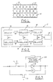
- Figures 1-3 generally depict the present invention.
- FIG. 1 is a schematic diagram of a solar-power generation panel 10 in which a plurality of solar modules 12 are arranged and mounted to the panel 10.
- An integrated circuit chip 14 acts as a master module controller. The integrated circuit chip 14 is used to configure, interconnect and control the solar modules 12 as desired.
- Each solar module 12 is a stand-alone unit that can be monitored and controlled by the integrated circuit chip 14.
- the modules 12 can be assembled in a variety of series and parallel strings on the solar panel 10.
- the integrated circuit chip 14 is capable of being programmed to monitor the modules 12, regulate power, and control the individual modules 14 in the array. Additionally, the integrated circuit chip 14 can be programmed to define the interconnections between modules 12 according to the solar panel 10 system design.
- Each module 12 contains a plurality of solar cells 16 mounted on a printed circuit board 18. All of the internal wiring of the module 12 is contained within the printed circuit board 18.
- the printed circuit board 18 has the solar cells 16 mounted thereto in an array and contains all of the interconnects and circuitry associated therewith, which would otherwise be difficult to implement using conventional hard wiring techniques.
- the printed circuit board 18 allows for easy manufacturing of the complicated array of solar cells 16.
- the circuitry is predetermined in the printed circuit board 18 and several path options are available between solar cells 16 on the module 12.
- the paths to be used in the module's construction 12 are determined by the function that the module 12 is to perform.
- the printed circuit board 18 can be either a rigid or flexible material.
- the substrate of a solar panel has a honeycomb structure.
- the thickness of the honeycomb substrate may be reduced to compensate for the extra weight associated with the rigid printed circuit board. Because the rigidity of the printed circuit board provides increased stability to the structure, it is possible to reduce the thickness of the honeycomb substrate without adversely affecting the structure of the solar panel.
- the printed circuit board is a flexible material, i.e. a thin sheet
- the solar cells could be mounted to the flexible printed circuit board, and then each printed circuit board is attached to the honeycomb substrate.
- the printed circuit board 17 for each module 12 which includes the layout and interconnection path options for all of the solar cells 16 within the module 12.
- the standard configuration makes mounting and testing of each of the plurality of solar cells 16 relatively easy. It is also convenient to identify and replace defective cells prior to mounting the module 12 onto a solar panel.
- the program in the integrated circuit chip 14 generates the configuration of the interconnection scheme for the solar cells 16.
- the module 12 allows each cell to be individually addressable using a matrix-labeling scheme, which specifies the cell location on the module 12.
- Figure 2 is an example of a simplified array of solar cells 16 having a matrix addressing system. The cells are labeled according to their row and column location. For example, in the first row, there are three columns and the cells 16 are labeled Cell(1,1), Cell(1,2) and Cell(1,3) respectively. Likewise in the second row, there are three columns and the cells 16 are labeled Cell(2,1), Cell(2,2) and Cell(2,3). While only two rows and three columns are shown in the present example, it is to be understood that the number of cells is not limited. One skilled in the art is capable of expanding on what is shown in Figure 2 to accomplish a much larger array of solar cells 16.
- the integrated circuit chip 14 is shown on the module 12. It should be noted that there are several methods of employing the integrated circuit chip 14. For example, it is possible that each module 12 has an individual integrated circuit chip 14 to control the solar cells 16 for that particular module 12. In this embodiment, it is possible that all of the integrated circuit chips on the solar panel can communicate with each other in order to control the overall panel. Another alternative may be that, in addition to each of the integrated circuits located on the modules, a master integrated circuit is located on the panel to communicate with each module's integrated circuit. Yet another alternative may have only one integrated circuit chip 14 for the entire system located on the solar panel that has the capability of addressing each solar cell on each module in the desired fashion. In any event, one of ordinary skill in the art is capable of designing many possible arrangements for the integrated circuit and how it communicates with the modules and the solar cells.
- FIG. 2 Also shown in Figure 2 is a possible interconnection scheme between the individual solar cells 16 on the module 12.
- a network of transistors 18 connects the solar cells 16 to each other. While transistors 18 are shown, it should be noted that other switching devices may be used to achieve the signal routing scheme desired.
- the network of transistors 18 allows the interconnection paths to be switched between solar cells 16.
- the integrated circuit 14 can be programmed to open or close the switching transistors 18 between cells in order to connect, or disconnect, a path therebetween. In this regard, the desired interconnection paths can be created.
- the interconnection paths are switchable. Therefore, it is possible to change the path at any time by altering the program in the integrated circuit chip 14. Any changes can be made before, during, or after assembly and even remotely while the solar panel is in orbit.
- the flexibility provided by the present invention is especially advantageous in situations in which the use of a solar panel requires changes to its output requirements while the spacecraft is in orbit. With the present invention it is possible to alter the output current and voltage of each module, and ultimately of the solar panel in total.
- each solar cell can be monitored individually.
- the reconfigurable module allows for the interconnection paths to be rerouted in order to avoid the failed solar cell.
- the reconfigurable design of the present invention allows for optimization and modification of the electrical configuration of the module, even after the module is physically assembled, and even after the spacecraft is in orbit.
- FIG 3 is an example of an electrical circuit that describes the function of the control integrated circuit chip 14 and how it provides monitoring, protection, and control of the solar cells in each module. All of the circuit components necessary to perform these functions can be placed on the integrated circuit chip 14.
- the voltage monitor 20 allows the control integrated circuit chip (not shown) to determine the functional state of the cell 16.
- the chip can determine whether the cell 16 is optimally functional, functional but with degraded performance, or not functional. Based on the state of the cell 16, the integrated circuit chip can determine if it should keep the cell use, or bypass the cell from the power generation system, and whether or not to reconfigure the cell string configuration.
- the transistors T1 and T2 are used to enable, disable, and reroute the signal paths to the cell 16. For example, if the cell 16 is functional, T1 is enabled and T2 is disabled. To bypass the cell 16, T2 is enabled and T1 is disabled.
- bypass scheme discussed above can also be used protect the cell 16.
- Reverse-bias is an undesirable condition that may occur due to partial shadowing of the solar panel.
- FIG 4 is a schematic of a group of solar cells having a reserve group 22 that is activated only when excess power is needed.
- the panel 10 has modules 12 arranged in a predefined pattern.
- a predetermined number of modules 12 form a reserve group 22 that is reserved for excess power demands.
- a transistor T1 is turned off and a transistor T2 is turned on.
- a voltage monitor 24 is used to compare the output voltage of the panel to a predetermined value. The comparison is used to decide when to activate the reserve group 22.
- T1 is shown in two places in Figure 4, it is the same transistor.
- the connection as indicated in Figure 4 is possible when all of the transistors are located on one integrated circuit chip.
- one skilled in the art is capable of accomplishing the same results with discrete components as well.
- the embodiment shown in Figure 4 avoids generating excess power at the beginning of the panel's life and reserves the power available in the reserve group 22 for the additional power and voltage that is typically required at the end of the panel's life.
- An advantage of this embodiment is that there is no need to dissipate excess energy typically generated at the beginning of the panel's life. The excess energy is typically dissipated at the satellite as excess heat. By avoiding the need to dissipate excess energy, the surface area of the satellite's heat dissipating surface can be reduced, thereby resulting in a weight reduction as well.
- the modularized design of the present invention provides a solar panel system that is versatile and easily manufactured.
- the present invention allows for optimization of the electrical configuration of the module at any point during the module's construction and use.
- Prior art methods rely on hard-wired configuration, which can only be modified by altering the physical wiring scheme.
- the present invention has a standard physical layout and the different electrical configurations are achieved by way of electrical routing of strings of cells rather than hard-wired modifications. Therefore, the present invention is extremely flexible and capable of accommodating different power generation requirements and specifications.
- manufacturing of the present invention is simplified over prior art assemblies.
- the standard physical layout can be mass-produced, as opposed to having to produce a panel that is specifically manufactured for a particular application on a spacecraft.
- automation in assembly and testing can be realized.
- the modularity of the standardized design according to the present invention allows for individual testing, assembly, and reconfiguration of each module prior to mounting the modules to the panel, and even thereafter.
- Another advantage of the modularity is the capability of the present invention to control and monitor each solar cell individually, using a centralized integrated circuit chip. This eliminates redundancy in the circuit and reduces the cost associated with duplicate circuits.
- the present invention relates to a reconfigurable solar panel system having a plurality of solar cells arranged in a predefined pattern on a printed circuit board having a predefined pattern of interconnection paths to form at least one solar cell module.
- the solar panel being made of at least one solar cell module and having the capability to be configured and reconfigured by programming at least one integrated circuit that communicates with each and every solar cell on the solar module.
- the present invention is capable of monitoring, controlling, and protecting the solar panel, as well as being reconfigured before, during and after the panel is assembled. With the present invention it is also possible to reconfigure the solar panel after it has been employed in an application, such as a satellite that is in orbit.
Landscapes
- Photovoltaic Devices (AREA)
Abstract
Description
Claims (12)
- A modular solar panel system (10) comprising:
at least one solar cell module (12) comprising:a printed circuit board medium (17) having a predefined pattern of interconnecting paths;a plurality of solar cells (16) arranged in a matrix on said printed circuit board medium (17) and being connected by said predefined pattern of interconnecting paths; andat least one integrated circuit (14) having a program defining a reconfigurable sub-pattern from said predefined pattern of interconnecting paths. - The system (10) as claimed in claim 1, characterized in that said at least one integrated circuit (14) is located on said solar panel (10) and is in communication with each of said plurality of solar cells (16).
- The system (10) as claimed in claim 1, characterized in that said at least one integrated circuit (14) is located on each of said at least one solar cell modules (12) and is in communication with each of said plurality of solar cells (16).
- The system (10) as claimed in claim 3, characterized in that an integrated circuit (14) located on said solar panel (10) is in communication with each of said at least one integrated circuits (14) located on each of said at least one solar cell modules (12).
- The system (10) as claimed in any of claims 1-4, characterized in that a predetermined number of said solar cell modules (12) further comprises a reserve group (22) for providing excess power to said system (10).
- A method for reconfiguring a solar panel system (10) having at least one solar cell module (12) having a plurality of solar cells (16) mounted on a printed circuit board (17) having a predefined pattern of interconnection paths connecting said plurality of solar cells (16), said method comprising the steps of
programming at least one integrated circuit chip (14) having the capability of addressing each solar cell (16) in said plurality of solar cells to define a desired signal route from said predefined interconnection paths and defining a power output and a current output for said solar panel system (10). - The method as claimed in claim 6, characterized in that said step of programming further comprises the steps of:programming an integrated circuit chip (14) on each of said at least one solar cell modules (12); andprogramming said at least one integrated circuit chip (14) to communicate with each of said integrated chips (14) on said at least one solar cell modules (12).
- The method as claimed in claim 6 or 7, characterized by the step of monitoring said solar panel (10) comprising the steps of;determining a functional state of at least one solar cell (16) in said plurality of solar cells (16);determining an operation for said at least one solar cell (16) based on said functional state of said solar cell (16).
- The method as claimed in any of claims 6-8, characterized by the step of regulating the power of said solar panel system (10).
- The method as claimed in any of claims 6-9, characterized by the step of protecting said solar panel system (10) by bypassing a solar cell (16) operating in an undesirable state.
- The method as claimed in any of claims 6-10, characterized in that said step of programming further comprises programming by remotely accessing said solar panel system (10).
- The method as claimed in any of claims 6-11, characterized by the steps ofreserving a predetermined number of solar cell modules (12) in an inactive state as a reserve group (22);comparing a predetermined output voltage with an actual output voltage of said solar panel system (10);activating said reserve group (22) when said actual output voltage is less than said predetermined output voltage.
Applications Claiming Priority (2)
| Application Number | Priority Date | Filing Date | Title |
|---|---|---|---|
| US09/580,286 US6350944B1 (en) | 2000-05-30 | 2000-05-30 | Solar module array with reconfigurable tile |
| US580286 | 2000-05-30 |
Publications (3)
| Publication Number | Publication Date |
|---|---|
| EP1160876A2 true EP1160876A2 (en) | 2001-12-05 |
| EP1160876A3 EP1160876A3 (en) | 2006-10-04 |
| EP1160876B1 EP1160876B1 (en) | 2014-11-12 |
Family
ID=24320475
Family Applications (1)
| Application Number | Title | Priority Date | Filing Date |
|---|---|---|---|
| EP01109720.1A Expired - Lifetime EP1160876B1 (en) | 2000-05-30 | 2001-04-20 | Reconfigurable solar module array |
Country Status (3)
| Country | Link |
|---|---|
| US (1) | US6350944B1 (en) |
| EP (1) | EP1160876B1 (en) |
| JP (1) | JP2002050782A (en) |
Cited By (16)
| Publication number | Priority date | Publication date | Assignee | Title |
|---|---|---|---|---|
| FR2894401A1 (en) * | 2005-12-07 | 2007-06-08 | Transenergie Sa | DEVICE FOR CONTROLLING AN ELECTRIC POWER GENERATION PLANT AND ELECTRIC POWER GENERATING PLANT USING SUCH A DEVICE |
| WO2007121955A1 (en) * | 2006-04-21 | 2007-11-01 | Wieland Electric Gmbh | Method for production of a solar cell with functional structures and a solar cell produced thereby |
| WO2008012040A1 (en) * | 2006-07-25 | 2008-01-31 | Diehl Ako Stiftung & Co. Kg | Photovoltaic arrangement |
| WO2011042904A1 (en) * | 2009-10-07 | 2011-04-14 | Pythagoras Solar Inc. | Photovoltaic module and array and method of manufacture thereof |
| DE102009046291A1 (en) | 2009-11-02 | 2011-05-12 | Robert Bosch Gmbh | Photovoltaic arrangement for conversion of solar energy into electrical energy, has nodes comprising control unit for controlling electrical connection of photo-voltaic modules that are directly connected with control unit |
| WO2011032741A3 (en) * | 2009-09-16 | 2012-04-05 | International Business Machines Corporation | Method for manufacturing a thin-film photovoltaic cell module encompassing an array of cells and photovoltaic cell module |
| DE102011077702A1 (en) | 2011-06-17 | 2012-12-20 | Robert Bosch Gmbh | Solar cell arrangement, has solar cell modules interconnected with common inverter, where each solar cell module comprises switch unit for switching at bus line in dependent of current value of internal state variable |
| US9868357B2 (en) | 2014-10-09 | 2018-01-16 | Paired Power, Inc. | Electric vehicle charging systems and methods |
| EP3412583A1 (en) * | 2017-06-06 | 2018-12-12 | Airbus Defence and Space GmbH | Energy supplying device for spacecraft |
| EP3416199A1 (en) * | 2017-06-12 | 2018-12-19 | The Boeing Company | Solar cell array with bypassed solar cells |
| EP3416198A1 (en) * | 2017-06-12 | 2018-12-19 | The Boeing Company | Solar cell array with changeable string length |
| US10763383B2 (en) | 2016-09-14 | 2020-09-01 | The Boeing Company | Nano-metal connections for a solar cell array |
| US11967923B2 (en) | 2018-03-28 | 2024-04-23 | The Boeing Company | Single sheet foldout solar array |
| US12100774B2 (en) | 2016-09-14 | 2024-09-24 | The Boeing Company | Solar cells for a solar cell array |
| US12244265B2 (en) | 2018-03-28 | 2025-03-04 | The Boeing Company | Wiring for a rigid panel solar array |
| US12528370B2 (en) | 2014-10-09 | 2026-01-20 | Paired Power, Inc. | Electric vehicle charging systems and methods |
Families Citing this family (136)
| Publication number | Priority date | Publication date | Assignee | Title |
|---|---|---|---|---|
| KR20000019144A (en) * | 1998-09-09 | 2000-04-06 | 이수근 | Portable multi-power device using solar battery |
| US8138413B2 (en) * | 2006-04-13 | 2012-03-20 | Daniel Luch | Collector grid and interconnect structures for photovoltaic arrays and modules |
| US8076568B2 (en) * | 2006-04-13 | 2011-12-13 | Daniel Luch | Collector grid and interconnect structures for photovoltaic arrays and modules |
| US8222513B2 (en) | 2006-04-13 | 2012-07-17 | Daniel Luch | Collector grid, electrode structures and interconnect structures for photovoltaic arrays and methods of manufacture |
| US8664030B2 (en) | 1999-03-30 | 2014-03-04 | Daniel Luch | Collector grid and interconnect structures for photovoltaic arrays and modules |
| US20090111206A1 (en) | 1999-03-30 | 2009-04-30 | Daniel Luch | Collector grid, electrode structures and interrconnect structures for photovoltaic arrays and methods of manufacture |
| US7507903B2 (en) | 1999-03-30 | 2009-03-24 | Daniel Luch | Substrate and collector grid structures for integrated series connected photovoltaic arrays and process of manufacture of such arrays |
| US20110067754A1 (en) * | 2000-02-04 | 2011-03-24 | Daniel Luch | Substrate structures for integrated series connected photovoltaic arrays and process of manufacture of such arrays |
| US8198696B2 (en) | 2000-02-04 | 2012-06-12 | Daniel Luch | Substrate structures for integrated series connected photovoltaic arrays and process of manufacture of such arrays |
| US7898054B2 (en) * | 2000-02-04 | 2011-03-01 | Daniel Luch | Substrate structures for integrated series connected photovoltaic arrays and process of manufacture of such arrays |
| US7898053B2 (en) * | 2000-02-04 | 2011-03-01 | Daniel Luch | Substrate structures for integrated series connected photovoltaic arrays and process of manufacture of such arrays |
| DE10107600C1 (en) * | 2001-02-17 | 2002-08-22 | Saint Gobain | Method for operating a photovoltaic solar module and photovoltaic solar module |
| US6635817B2 (en) * | 2001-12-06 | 2003-10-21 | Koninklijke Philips Electronics N.V. | Solar cell array having lattice or matrix structure and method of arranging solar cells and panels |
| US6686533B2 (en) * | 2002-01-29 | 2004-02-03 | Israel Aircraft Industries Ltd. | System and method for converting solar energy to electricity |
| JP4003655B2 (en) * | 2003-02-12 | 2007-11-07 | 三菱電機株式会社 | Solar panel |
| TW200534491A (en) * | 2004-04-14 | 2005-10-16 | Easy Harvest Entpr Company Ltd | Method of self-generating power, power accumulating, distributing, supplying by transforming solar energy and electric energy mutually and the system thereof |
| EP1602934A1 (en) * | 2004-06-04 | 2005-12-07 | Hendrik Oldenkamp | Sensor device for monitoring the operation of a PV system, and PV system with such a sensor device |
| US7417356B2 (en) * | 2004-12-20 | 2008-08-26 | Npl Associates | Power conversion circuitry |
| US11881814B2 (en) | 2005-12-05 | 2024-01-23 | Solaredge Technologies Ltd. | Testing of a photovoltaic panel |
| US10693415B2 (en) | 2007-12-05 | 2020-06-23 | Solaredge Technologies Ltd. | Testing of a photovoltaic panel |
| US9006563B2 (en) | 2006-04-13 | 2015-04-14 | Solannex, Inc. | Collector grid and interconnect structures for photovoltaic arrays and modules |
| US8884155B2 (en) | 2006-04-13 | 2014-11-11 | Daniel Luch | Collector grid and interconnect structures for photovoltaic arrays and modules |
| US9865758B2 (en) | 2006-04-13 | 2018-01-09 | Daniel Luch | Collector grid and interconnect structures for photovoltaic arrays and modules |
| US8822810B2 (en) | 2006-04-13 | 2014-09-02 | Daniel Luch | Collector grid and interconnect structures for photovoltaic arrays and modules |
| US8729385B2 (en) | 2006-04-13 | 2014-05-20 | Daniel Luch | Collector grid and interconnect structures for photovoltaic arrays and modules |
| US9236512B2 (en) | 2006-04-13 | 2016-01-12 | Daniel Luch | Collector grid and interconnect structures for photovoltaic arrays and modules |
| US9130401B2 (en) | 2006-12-06 | 2015-09-08 | Solaredge Technologies Ltd. | Distributed power harvesting systems using DC power sources |
| US9112379B2 (en) | 2006-12-06 | 2015-08-18 | Solaredge Technologies Ltd. | Pairing of components in a direct current distributed power generation system |
| US8319471B2 (en) | 2006-12-06 | 2012-11-27 | Solaredge, Ltd. | Battery power delivery module |
| US9088178B2 (en) | 2006-12-06 | 2015-07-21 | Solaredge Technologies Ltd | Distributed power harvesting systems using DC power sources |
| US8013472B2 (en) | 2006-12-06 | 2011-09-06 | Solaredge, Ltd. | Method for distributed power harvesting using DC power sources |
| US11888387B2 (en) | 2006-12-06 | 2024-01-30 | Solaredge Technologies Ltd. | Safety mechanisms, wake up and shutdown methods in distributed power installations |
| US8816535B2 (en) | 2007-10-10 | 2014-08-26 | Solaredge Technologies, Ltd. | System and method for protection during inverter shutdown in distributed power installations |
| US11687112B2 (en) | 2006-12-06 | 2023-06-27 | Solaredge Technologies Ltd. | Distributed power harvesting systems using DC power sources |
| US11569659B2 (en) | 2006-12-06 | 2023-01-31 | Solaredge Technologies Ltd. | Distributed power harvesting systems using DC power sources |
| US8618692B2 (en) | 2007-12-04 | 2013-12-31 | Solaredge Technologies Ltd. | Distributed power system using direct current power sources |
| US12316274B2 (en) | 2006-12-06 | 2025-05-27 | Solaredge Technologies Ltd. | Pairing of components in a direct current distributed power generation system |
| US11296650B2 (en) | 2006-12-06 | 2022-04-05 | Solaredge Technologies Ltd. | System and method for protection during inverter shutdown in distributed power installations |
| US8319483B2 (en) | 2007-08-06 | 2012-11-27 | Solaredge Technologies Ltd. | Digital average input current control in power converter |
| US8947194B2 (en) | 2009-05-26 | 2015-02-03 | Solaredge Technologies Ltd. | Theft detection and prevention in a power generation system |
| US8473250B2 (en) | 2006-12-06 | 2013-06-25 | Solaredge, Ltd. | Monitoring of distributed power harvesting systems using DC power sources |
| US12676488B2 (en) | 2006-12-06 | 2026-07-07 | Solaredge Technologies Ltd. | System and method for protection during inverter shutdown in distributed power installations |
| US11735910B2 (en) | 2006-12-06 | 2023-08-22 | Solaredge Technologies Ltd. | Distributed power system using direct current power sources |
| US11309832B2 (en) | 2006-12-06 | 2022-04-19 | Solaredge Technologies Ltd. | Distributed power harvesting systems using DC power sources |
| US11855231B2 (en) | 2006-12-06 | 2023-12-26 | Solaredge Technologies Ltd. | Distributed power harvesting systems using DC power sources |
| US8963369B2 (en) | 2007-12-04 | 2015-02-24 | Solaredge Technologies Ltd. | Distributed power harvesting systems using DC power sources |
| US8384243B2 (en) | 2007-12-04 | 2013-02-26 | Solaredge Technologies Ltd. | Distributed power harvesting systems using DC power sources |
| US20080142071A1 (en) * | 2006-12-15 | 2008-06-19 | Miasole | Protovoltaic module utilizing a flex circuit for reconfiguration |
| TW200832795A (en) * | 2007-01-29 | 2008-08-01 | Syspotek Corp | Fuel cell apparatus containing series/parallel connected circuit |
| US20080178923A1 (en) * | 2007-01-29 | 2008-07-31 | Lucky Power Technology Co., Ltd. | Power generation diode module in roof tile |
| US20090139561A1 (en) * | 2007-10-18 | 2009-06-04 | Searete Llc, A Limited Liability Corporation Of The State Of Delaware | Method and system for converting light to electric power |
| US20090140126A1 (en) * | 2007-10-18 | 2009-06-04 | Searete Llc, A Limited Liability Corporation Of The State Of Delaware | Method and system for converting light to electric power |
| US20090139559A1 (en) * | 2007-10-18 | 2009-06-04 | Searete Llc, A Limited Liability Corporation Of The State Of Delaware | Method and system for converting light to electric power |
| US20090139560A1 (en) * | 2007-10-18 | 2009-06-04 | Searete Llc, A Limited Liability Corporation Of The State Of Delaware | Method and system for converting light to electric power |
| US20090101194A1 (en) * | 2007-10-18 | 2009-04-23 | Searete Llc, A Limited Liability Corporation Of The State Of Delaware | Method and system for converting light to electric power |
| US20090272420A1 (en) * | 2007-10-18 | 2009-11-05 | Searete Llc | Method and system for converting light to electric power |
| US20090242012A1 (en) * | 2007-10-18 | 2009-10-01 | Searete Llc, A Limited Liability Corporation Of The State Of Delaware | Method and system for converting light to electric power |
| US20090206672A1 (en) * | 2007-10-18 | 2009-08-20 | Searete Llc | Method and system for converting light to electric power |
| US7884278B2 (en) * | 2007-11-02 | 2011-02-08 | Tigo Energy, Inc. | Apparatuses and methods to reduce safety risks associated with photovoltaic systems |
| US11228278B2 (en) | 2007-11-02 | 2022-01-18 | Tigo Energy, Inc. | System and method for enhanced watch dog in solar panel installations |
| US8933321B2 (en) | 2009-02-05 | 2015-01-13 | Tigo Energy, Inc. | Systems and methods for an enhanced watchdog in solar module installations |
| US7602080B1 (en) * | 2008-11-26 | 2009-10-13 | Tigo Energy, Inc. | Systems and methods to balance solar panels in a multi-panel system |
| WO2009072076A2 (en) | 2007-12-05 | 2009-06-11 | Solaredge Technologies Ltd. | Current sensing on a mosfet |
| JP2011507465A (en) | 2007-12-05 | 2011-03-03 | ソラレッジ テクノロジーズ リミテッド | Safety mechanism, wake-up method and shutdown method in distributed power installation |
| US11264947B2 (en) | 2007-12-05 | 2022-03-01 | Solaredge Technologies Ltd. | Testing of a photovoltaic panel |
| US8289742B2 (en) | 2007-12-05 | 2012-10-16 | Solaredge Ltd. | Parallel connected inverters |
| US9291696B2 (en) | 2007-12-05 | 2016-03-22 | Solaredge Technologies Ltd. | Photovoltaic system power tracking method |
| DE102008003272A1 (en) * | 2008-01-05 | 2009-07-09 | Hans-Hermann Hunfeld | Monitoring unit for photovoltaic modules |
| EP2085986A1 (en) * | 2008-01-30 | 2009-08-05 | Swerea IVF AB | A sealed monolithic electrochemical system |
| EP2269290B1 (en) | 2008-03-24 | 2018-12-19 | Solaredge Technologies Ltd. | Switch mode converter including active clamp for achieving zero voltage switching |
| US20090266397A1 (en) * | 2008-04-23 | 2009-10-29 | Gm Global Technology Operations, Inc. | Solar battery charging system and optional solar hydrogen production system for vehicle propulsion |
| WO2009136358A1 (en) | 2008-05-05 | 2009-11-12 | Solaredge Technologies Ltd. | Direct current power combiner |
| US8022571B2 (en) * | 2008-07-18 | 2011-09-20 | Apple Inc. | Power management circuitry and solar cells |
| TW201015732A (en) * | 2008-10-06 | 2010-04-16 | Pegatron Corp | Solar cell module |
| US8115340B2 (en) * | 2008-12-12 | 2012-02-14 | Paceco Corp. | System for controlling power from a photovoltaic array by selectively configurating connections between photovoltaic panels |
| US20100152072A1 (en) * | 2008-12-17 | 2010-06-17 | Chevron Oronite Company Llc | Lubricating oil compositions |
| FR2940476B1 (en) | 2008-12-18 | 2011-02-25 | Total Sa | ELECTRONIC MANAGEMENT SYSTEM FOR PHOTOVOLTAIC CELLS |
| US20100186795A1 (en) * | 2009-01-28 | 2010-07-29 | Stephen Joseph Gaul | Connection systems and methods for solar cells |
| US20100191383A1 (en) * | 2009-01-28 | 2010-07-29 | Intersil Americas, Inc. | Connection systems and methods for solar cells |
| US20100198424A1 (en) * | 2009-01-30 | 2010-08-05 | Toru Takehara | Method for reconfigurably connecting photovoltaic panels in a photovoltaic array |
| JP5458696B2 (en) * | 2009-06-29 | 2014-04-02 | コニカミノルタ株式会社 | Photovoltaic power generation system and solar power generation cell, controller, and user terminal constituting the system |
| US12418177B2 (en) | 2009-10-24 | 2025-09-16 | Solaredge Technologies Ltd. | Distributed power system using direct current power sources |
| JP5311495B2 (en) * | 2009-12-15 | 2013-10-09 | 独立行政法人産業技術総合研究所 | Solar cell module |
| WO2011084545A2 (en) * | 2009-12-16 | 2011-07-14 | Nagendra Cherukupalli | Systems, circuits, and methods for reconfiguring solar cells of an adaptive solar power system |
| US8854193B2 (en) | 2009-12-29 | 2014-10-07 | Tigo Energy, Inc. | Systems and methods for remote or local shut-off of a photovoltaic system |
| EP2561596B1 (en) | 2010-04-22 | 2019-05-22 | Tigo Energy, Inc. | System and method for enhanced watch dog in solar panel installations |
| US20110290296A1 (en) * | 2010-05-27 | 2011-12-01 | Palo Alto Research Center Incorporated | Flexible tiled photovoltaic module |
| US8525369B2 (en) | 2010-06-02 | 2013-09-03 | GM Global Technology Operations LLC | Method and device for optimizing the use of solar electrical power |
| US8358489B2 (en) | 2010-08-27 | 2013-01-22 | International Rectifier Corporation | Smart photovoltaic panel and method for regulating power using same |
| JP2012074676A (en) * | 2010-09-02 | 2012-04-12 | Seiko Instruments Inc | Solar panel, wristwatch, and method for manufacturing solar panel |
| US10673229B2 (en) | 2010-11-09 | 2020-06-02 | Solaredge Technologies Ltd. | Arc detection and prevention in a power generation system |
| US10673222B2 (en) | 2010-11-09 | 2020-06-02 | Solaredge Technologies Ltd. | Arc detection and prevention in a power generation system |
| US10230310B2 (en) | 2016-04-05 | 2019-03-12 | Solaredge Technologies Ltd | Safety switch for photovoltaic systems |
| GB2485527B (en) | 2010-11-09 | 2012-12-19 | Solaredge Technologies Ltd | Arc detection and prevention in a power generation system |
| US8604330B1 (en) | 2010-12-06 | 2013-12-10 | 4Power, Llc | High-efficiency solar-cell arrays with integrated devices and methods for forming them |
| GB2486408A (en) | 2010-12-09 | 2012-06-20 | Solaredge Technologies Ltd | Disconnection of a string carrying direct current |
| GB2483317B (en) | 2011-01-12 | 2012-08-22 | Solaredge Technologies Ltd | Serially connected inverters |
| US12665546B2 (en) | 2011-01-28 | 2026-06-23 | Solaredge Technologies Ltd. | Pairing of components in a direct current distributed power generation system |
| US8730657B2 (en) | 2011-06-24 | 2014-05-20 | Blackberry Limited | Mobile computing devices |
| US8570005B2 (en) | 2011-09-12 | 2013-10-29 | Solaredge Technologies Ltd. | Direct current link circuit |
| EP2587334A1 (en) * | 2011-10-24 | 2013-05-01 | Imec | Reconfigurable PV configuration |
| KR20140095565A (en) | 2011-11-20 | 2014-08-01 | 솔렉셀, 인크. | Smart photovoltaic cells and modules |
| US10181541B2 (en) | 2011-11-20 | 2019-01-15 | Tesla, Inc. | Smart photovoltaic cells and modules |
| GB2498365A (en) | 2012-01-11 | 2013-07-17 | Solaredge Technologies Ltd | Photovoltaic module |
| DE102012106130A1 (en) * | 2012-01-11 | 2013-07-11 | Fraunhofer-Gesellschaft zur Förderung der angewandten Forschung e.V. | Simplified PV system creation with a consecutively placed system block |
| US9572254B2 (en) | 2012-01-17 | 2017-02-14 | Xerox Corporation | Suspended lattice for electrical interconnects |
| GB2498791A (en) | 2012-01-30 | 2013-07-31 | Solaredge Technologies Ltd | Photovoltaic panel circuitry |
| US9853565B2 (en) | 2012-01-30 | 2017-12-26 | Solaredge Technologies Ltd. | Maximized power in a photovoltaic distributed power system |
| GB2498790A (en) | 2012-01-30 | 2013-07-31 | Solaredge Technologies Ltd | Maximising power in a photovoltaic distributed power system |
| GB2499991A (en) | 2012-03-05 | 2013-09-11 | Solaredge Technologies Ltd | DC link circuit for photovoltaic array |
| EP2856850A4 (en) | 2012-05-29 | 2016-04-06 | Essence Solar Solutions Ltd | AUTOMATIC ALIGNMENT SOLDERING |
| US10115841B2 (en) | 2012-06-04 | 2018-10-30 | Solaredge Technologies Ltd. | Integrated photovoltaic panel circuitry |
| US9356173B2 (en) | 2012-08-31 | 2016-05-31 | Sandia Corporation | Dynamically reconfigurable photovoltaic system |
| EP2770539A1 (en) | 2013-02-20 | 2014-08-27 | Total Marketing Services | Electronic management system for electricity generating cells, electricity generating system and method for electronically managing energy flow |
| US9548619B2 (en) | 2013-03-14 | 2017-01-17 | Solaredge Technologies Ltd. | Method and apparatus for storing and depleting energy |
| US20140261614A1 (en) * | 2013-03-14 | 2014-09-18 | First Solar, Inc. | Method of installing and operating a solar module array |
| US9941813B2 (en) | 2013-03-14 | 2018-04-10 | Solaredge Technologies Ltd. | High frequency multi-level inverter |
| EP2779251B1 (en) | 2013-03-15 | 2019-02-27 | Solaredge Technologies Ltd. | Bypass mechanism |
| US10784815B2 (en) | 2013-04-13 | 2020-09-22 | Sigmagen, Inc. | Solar photovoltaic module remote access module switch and real-time temperature monitoring |
| US9318974B2 (en) | 2014-03-26 | 2016-04-19 | Solaredge Technologies Ltd. | Multi-level inverter with flying capacitor topology |
| US10271437B2 (en) | 2014-08-14 | 2019-04-23 | The United States Of America As Represented By The Secretary Of The Army | Motion-based reconfigurable microelectronics system |
| KR101859799B1 (en) | 2015-08-07 | 2018-05-21 | 한국과학기술원 | Reconfigurable method of photovoltaic array and vehicular photovoltaic system |
| US20170264237A1 (en) * | 2016-03-08 | 2017-09-14 | Neotec Energy Pty. Ltd. | Method and apparatus for solar power generation |
| US12057807B2 (en) | 2016-04-05 | 2024-08-06 | Solaredge Technologies Ltd. | Chain of power devices |
| US11018623B2 (en) | 2016-04-05 | 2021-05-25 | Solaredge Technologies Ltd. | Safety switch for photovoltaic systems |
| US11177663B2 (en) | 2016-04-05 | 2021-11-16 | Solaredge Technologies Ltd. | Chain of power devices |
| US10673377B2 (en) * | 2017-03-29 | 2020-06-02 | Neotec Energy Pty Ltd. | Method and apparatus for alternating circuit solar power generation |
| US10439554B2 (en) | 2017-06-08 | 2019-10-08 | Jeff Kotowski | Method and apparatus for solar panel protection and control system |
| JP7656393B2 (en) * | 2017-06-12 | 2025-04-03 | ザ・ボーイング・カンパニー | Solar cell array with variable string length - Patents.com |
| JP2019050351A (en) * | 2017-06-12 | 2019-03-28 | ザ・ボーイング・カンパニーThe Boeing Company | Solar cell array with diverted solar cells |
| US10580919B2 (en) | 2017-12-07 | 2020-03-03 | Solaero Technologies Corp. | Space solar cell arrays with blocking diodes |
| CN109244170A (en) * | 2018-10-31 | 2019-01-18 | 珠海格力电器股份有限公司 | Photovoltaic module and household photovoltaic power generation system |
| JP7369790B2 (en) * | 2019-06-03 | 2023-10-26 | エアロジェット ロケットダイン インコーポレイテッド | Reconfigurable power processing unit for spacecraft operation |
| JP7466984B2 (en) * | 2019-11-15 | 2024-04-15 | 京セラ株式会社 | Control device, solar cell system, and control method |
| US12003210B2 (en) | 2020-04-13 | 2024-06-04 | The Boeing Company | Solar array attachment |
| US12183836B2 (en) | 2022-04-15 | 2024-12-31 | Northrop Grumman Systems Corporation | Reconfigurable solar array for stable output voltage over a range of temperatures with high operational efficiency |
Family Cites Families (17)
| Publication number | Priority date | Publication date | Assignee | Title |
|---|---|---|---|---|
| US3636539A (en) * | 1970-11-18 | 1972-01-18 | Nasa | Optimum performance spacecraft solar cell system |
| GB1424383A (en) * | 1973-08-11 | 1976-02-11 | Hawker Siddeley Dynamics Ltd | Tpower systems for spacecraft or orbiting satellites |
| US4019924A (en) | 1975-11-14 | 1977-04-26 | Mobil Tyco Solar Energy Corporation | Solar cell mounting and interconnecting assembly |
| US4175249A (en) * | 1978-06-19 | 1979-11-20 | The United States Of America As Represented By The Administrator Of The National Aeronautics And Space Administration | Self-reconfiguring solar cell system |
| US5021099A (en) | 1988-08-09 | 1991-06-04 | The Boeing Company | Solar cell interconnection and packaging using tape carrier |
| US5185042A (en) | 1991-08-01 | 1993-02-09 | Trw Inc. | Generic solar cell array using a printed circuit substrate |
| US5530335A (en) * | 1993-05-11 | 1996-06-25 | Trw Inc. | Battery regulated bus spacecraft power control system |
| JPH06334208A (en) * | 1993-05-19 | 1994-12-02 | Nec Corp | Solar power plant |
| US5453729A (en) * | 1993-07-28 | 1995-09-26 | Chu; Chiu-Tsai | Solar warning light |
| US5460659A (en) | 1993-12-10 | 1995-10-24 | Spectrolab, Inc. | Concentrating photovoltaic module and fabrication method |
| JPH07177652A (en) * | 1993-12-17 | 1995-07-14 | Canon Inc | Photovoltaic system and protection method for photovoltaic system |
| US5669987A (en) * | 1994-04-13 | 1997-09-23 | Canon Kabushiki Kaisha | Abnormality detection method, abnormality detection apparatus, and solar cell power generating system using the same |
| US5466302A (en) | 1994-05-09 | 1995-11-14 | Regents Of The University Of California | Solar cell array interconnects |
| US5644207A (en) * | 1995-12-11 | 1997-07-01 | The Johns Hopkins University | Integrated power source |
| US6020555A (en) * | 1997-05-01 | 2000-02-01 | Amonix, Inc. | System for protecting series connected solar panels against failure due to mechanical damage of individual solar cells while maintaining full output of the remaining cells |
| GB9725128D0 (en) * | 1997-11-27 | 1998-01-28 | Weinberg Alan H | Solar array system |
| US6060790A (en) * | 1998-02-24 | 2000-05-09 | Lockheed Martin Corporation | Solar array switching unit |
-
2000
- 2000-05-30 US US09/580,286 patent/US6350944B1/en not_active Expired - Lifetime
-
2001
- 2001-04-20 EP EP01109720.1A patent/EP1160876B1/en not_active Expired - Lifetime
- 2001-05-29 JP JP2001160585A patent/JP2002050782A/en active Pending
Cited By (21)
| Publication number | Priority date | Publication date | Assignee | Title |
|---|---|---|---|---|
| FR2894401A1 (en) * | 2005-12-07 | 2007-06-08 | Transenergie Sa | DEVICE FOR CONTROLLING AN ELECTRIC POWER GENERATION PLANT AND ELECTRIC POWER GENERATING PLANT USING SUCH A DEVICE |
| WO2007121955A1 (en) * | 2006-04-21 | 2007-11-01 | Wieland Electric Gmbh | Method for production of a solar cell with functional structures and a solar cell produced thereby |
| WO2008012040A1 (en) * | 2006-07-25 | 2008-01-31 | Diehl Ako Stiftung & Co. Kg | Photovoltaic arrangement |
| WO2011032741A3 (en) * | 2009-09-16 | 2012-04-05 | International Business Machines Corporation | Method for manufacturing a thin-film photovoltaic cell module encompassing an array of cells and photovoltaic cell module |
| WO2011042904A1 (en) * | 2009-10-07 | 2011-04-14 | Pythagoras Solar Inc. | Photovoltaic module and array and method of manufacture thereof |
| DE102009046291A1 (en) | 2009-11-02 | 2011-05-12 | Robert Bosch Gmbh | Photovoltaic arrangement for conversion of solar energy into electrical energy, has nodes comprising control unit for controlling electrical connection of photo-voltaic modules that are directly connected with control unit |
| DE102011077702A1 (en) | 2011-06-17 | 2012-12-20 | Robert Bosch Gmbh | Solar cell arrangement, has solar cell modules interconnected with common inverter, where each solar cell module comprises switch unit for switching at bus line in dependent of current value of internal state variable |
| US9868357B2 (en) | 2014-10-09 | 2018-01-16 | Paired Power, Inc. | Electric vehicle charging systems and methods |
| US12528370B2 (en) | 2014-10-09 | 2026-01-20 | Paired Power, Inc. | Electric vehicle charging systems and methods |
| US12100774B2 (en) | 2016-09-14 | 2024-09-24 | The Boeing Company | Solar cells for a solar cell array |
| US10763383B2 (en) | 2016-09-14 | 2020-09-01 | The Boeing Company | Nano-metal connections for a solar cell array |
| US11437533B2 (en) | 2016-09-14 | 2022-09-06 | The Boeing Company | Solar cells for a solar cell array |
| US12615851B2 (en) | 2016-09-14 | 2026-04-28 | The Boeing Company | Prefabricated conductors on a substrate to facilitate corner connections for a solar cell array |
| US12696550B2 (en) | 2016-09-14 | 2026-07-28 | The Boeing Company | Power routing module with a switching matrix for a solar cell array |
| US10934027B2 (en) | 2017-06-06 | 2021-03-02 | Airbus Defence and Space GmbH | Energy supplying device for spacecraft |
| EP3412583A1 (en) * | 2017-06-06 | 2018-12-12 | Airbus Defence and Space GmbH | Energy supplying device for spacecraft |
| EP3416198A1 (en) * | 2017-06-12 | 2018-12-19 | The Boeing Company | Solar cell array with changeable string length |
| EP3416199A1 (en) * | 2017-06-12 | 2018-12-19 | The Boeing Company | Solar cell array with bypassed solar cells |
| US12490523B2 (en) | 2017-06-12 | 2025-12-02 | The Boeing Company | Solar cell array with changeable string length |
| US11967923B2 (en) | 2018-03-28 | 2024-04-23 | The Boeing Company | Single sheet foldout solar array |
| US12244265B2 (en) | 2018-03-28 | 2025-03-04 | The Boeing Company | Wiring for a rigid panel solar array |
Also Published As
| Publication number | Publication date |
|---|---|
| US6350944B1 (en) | 2002-02-26 |
| EP1160876B1 (en) | 2014-11-12 |
| EP1160876A3 (en) | 2006-10-04 |
| JP2002050782A (en) | 2002-02-15 |
Similar Documents
| Publication | Publication Date | Title |
|---|---|---|
| US6350944B1 (en) | Solar module array with reconfigurable tile | |
| JP7607014B2 (en) | Solar cells for solar cell arrays | |
| US7372162B2 (en) | Multiple selectable function integrated circuit module | |
| US5185042A (en) | Generic solar cell array using a printed circuit substrate | |
| EP3297042B1 (en) | Power routing module with a switching matrix for a solar cell array | |
| CA2108711A1 (en) | Electronic assemblies | |
| EP3416199B1 (en) | Solar cell array with bypassed solar cells | |
| US20220367741A1 (en) | Solar cells for a solar cell array | |
| EP3416198B1 (en) | Solar cell array with changeable string length | |
| US5949212A (en) | Integrated solar cell array and power regulator | |
| US5140189A (en) | WSI decoder and patch circuit | |
| JP2019050351A (en) | Solar cell array with diverted solar cells | |
| EP0370189B1 (en) | Modular computer system | |
| JP2022082513A (en) | Space solar cell with customized voltage | |
| EP4521885A2 (en) | Solar cells for a solar cell array | |
| JP2019050350A (en) | Solar cell array with variable string length |
Legal Events
| Date | Code | Title | Description |
|---|---|---|---|
| PUAI | Public reference made under article 153(3) epc to a published international application that has entered the european phase |
Free format text: ORIGINAL CODE: 0009012 |
|
| AK | Designated contracting states |
Kind code of ref document: A2 Designated state(s): AT BE CH CY DE DK ES FI FR GB GR IE IT LI LU MC NL PT SE TR |
|
| AX | Request for extension of the european patent |
Free format text: AL;LT;LV;MK;RO;SI |
|
| PUAL | Search report despatched |
Free format text: ORIGINAL CODE: 0009013 |
|
| AK | Designated contracting states |
Kind code of ref document: A3 Designated state(s): AT BE CH CY DE DK ES FI FR GB GR IE IT LI LU MC NL PT SE TR |
|
| AX | Request for extension of the european patent |
Extension state: AL LT LV MK RO SI |
|
| 17P | Request for examination filed |
Effective date: 20070308 |
|
| AKX | Designation fees paid |
Designated state(s): DE FR GB |
|
| 17Q | First examination report despatched |
Effective date: 20090311 |
|
| GRAP | Despatch of communication of intention to grant a patent |
Free format text: ORIGINAL CODE: EPIDOSNIGR1 |
|
| INTG | Intention to grant announced |
Effective date: 20131118 |
|
| GRAP | Despatch of communication of intention to grant a patent |
Free format text: ORIGINAL CODE: EPIDOSNIGR1 |
|
| INTG | Intention to grant announced |
Effective date: 20140527 |
|
| GRAS | Grant fee paid |
Free format text: ORIGINAL CODE: EPIDOSNIGR3 |
|
| GRAA | (expected) grant |
Free format text: ORIGINAL CODE: 0009210 |
|
| AK | Designated contracting states |
Kind code of ref document: B1 Designated state(s): DE FR GB |
|
| REG | Reference to a national code |
Ref country code: GB Ref legal event code: FG4D |
|
| REG | Reference to a national code |
Ref country code: DE Ref legal event code: R096 Ref document number: 60149099 Country of ref document: DE Effective date: 20141224 |
|
| REG | Reference to a national code |
Ref country code: DE Ref legal event code: R097 Ref document number: 60149099 Country of ref document: DE |
|
| PLBE | No opposition filed within time limit |
Free format text: ORIGINAL CODE: 0009261 |
|
| STAA | Information on the status of an ep patent application or granted ep patent |
Free format text: STATUS: NO OPPOSITION FILED WITHIN TIME LIMIT |
|
| 26N | No opposition filed |
Effective date: 20150813 |
|
| REG | Reference to a national code |
Ref country code: FR Ref legal event code: PLFP Year of fee payment: 16 |
|
| REG | Reference to a national code |
Ref country code: FR Ref legal event code: PLFP Year of fee payment: 17 |
|
| REG | Reference to a national code |
Ref country code: FR Ref legal event code: PLFP Year of fee payment: 18 |
|
| PGFP | Annual fee paid to national office [announced via postgrant information from national office to epo] |
Ref country code: DE Payment date: 20200429 Year of fee payment: 20 Ref country code: FR Payment date: 20200427 Year of fee payment: 20 |
|
| PGFP | Annual fee paid to national office [announced via postgrant information from national office to epo] |
Ref country code: GB Payment date: 20200427 Year of fee payment: 20 |
|
| REG | Reference to a national code |
Ref country code: DE Ref legal event code: R071 Ref document number: 60149099 Country of ref document: DE |
|
| REG | Reference to a national code |
Ref country code: GB Ref legal event code: PE20 Expiry date: 20210419 |
|
| PG25 | Lapsed in a contracting state [announced via postgrant information from national office to epo] |
Ref country code: GB Free format text: LAPSE BECAUSE OF EXPIRATION OF PROTECTION Effective date: 20210419 |