EP1160811A2 - Key unit and switch body and door switch using the same - Google Patents
Key unit and switch body and door switch using the same Download PDFInfo
- Publication number
- EP1160811A2 EP1160811A2 EP01110460A EP01110460A EP1160811A2 EP 1160811 A2 EP1160811 A2 EP 1160811A2 EP 01110460 A EP01110460 A EP 01110460A EP 01110460 A EP01110460 A EP 01110460A EP 1160811 A2 EP1160811 A2 EP 1160811A2
- Authority
- EP
- European Patent Office
- Prior art keywords
- door
- key
- push rod
- unit
- switch
- Prior art date
- Legal status (The legal status is an assumption and is not a legal conclusion. Google has not performed a legal analysis and makes no representation as to the accuracy of the status listed.)
- Granted
Links
- 230000007246 mechanism Effects 0.000 claims abstract description 52
- 238000003780 insertion Methods 0.000 claims abstract description 23
- 230000037431 insertion Effects 0.000 claims abstract description 23
- 230000009471 action Effects 0.000 claims description 12
- 238000003825 pressing Methods 0.000 claims description 9
- 239000013013 elastic material Substances 0.000 claims description 4
- 238000006073 displacement reaction Methods 0.000 claims 6
- 238000005520 cutting process Methods 0.000 description 3
- 238000007689 inspection Methods 0.000 description 3
- 230000008439 repair process Effects 0.000 description 3
- 229920001875 Ebonite Polymers 0.000 description 2
- 238000004519 manufacturing process Methods 0.000 description 2
- 238000012986 modification Methods 0.000 description 2
- 230000004048 modification Effects 0.000 description 2
- 239000004065 semiconductor Substances 0.000 description 2
- 238000010276 construction Methods 0.000 description 1
- 238000001514 detection method Methods 0.000 description 1
- 238000009434 installation Methods 0.000 description 1
- 239000002184 metal Substances 0.000 description 1
- 229920005989 resin Polymers 0.000 description 1
- 239000011347 resin Substances 0.000 description 1
- 230000004044 response Effects 0.000 description 1
- 229910001220 stainless steel Inorganic materials 0.000 description 1
- 239000010935 stainless steel Substances 0.000 description 1
- 238000003466 welding Methods 0.000 description 1
Images


Classifications
-
- H—ELECTRICITY
- H01—ELECTRIC ELEMENTS
- H01H—ELECTRIC SWITCHES; RELAYS; SELECTORS; EMERGENCY PROTECTIVE DEVICES
- H01H3/00—Mechanisms for operating contacts
- H01H3/02—Operating parts, i.e. for operating driving mechanism by a mechanical force external to the switch
- H01H3/16—Operating parts, i.e. for operating driving mechanism by a mechanical force external to the switch adapted for actuation at a limit or other predetermined position in the path of a body, the relative movement of switch and body being primarily for a purpose other than the actuation of the switch, e.g. for a door switch, a limit switch, a floor-levelling switch of a lift
- H01H3/161—Operating parts, i.e. for operating driving mechanism by a mechanical force external to the switch adapted for actuation at a limit or other predetermined position in the path of a body, the relative movement of switch and body being primarily for a purpose other than the actuation of the switch, e.g. for a door switch, a limit switch, a floor-levelling switch of a lift for actuation by moving a closing member, e.g. door, cover or lid
-
- H—ELECTRICITY
- H01—ELECTRIC ELEMENTS
- H01H—ELECTRIC SWITCHES; RELAYS; SELECTORS; EMERGENCY PROTECTIVE DEVICES
- H01H27/00—Switches operated by a removable member, e.g. key, plug or plate; Switches operated by setting members according to a single predetermined combination out of several possible settings
- H01H27/002—Switches operated by a removable member, e.g. key, plug or plate; Switches operated by setting members according to a single predetermined combination out of several possible settings wherein one single insertion movement of a key comprises an unlocking stroke and a switch actuating stroke, e.g. security switch for safety guards
Definitions
- the present invention relates to a door switch for turning ON/OFF a contact as interlocked with the door opening and closing action and, more particularly to, a door switch used for a door provided at a doorway of a guard such as a protection fence or wall installed so as to surround a variety of machines.
- a variety of machines such as machine tools, semiconductor manufacturing equipment and food processing machines are typically surrounded by a guard such as a protection fence or wall. The operator is prevented from inadvertently coming in contact with those machines in operation by the guard.
- a doorway of such a guard is provided with a door for permitting the operator to enter for inspection and repair of the machines.
- a door switch is equipped to such a door for turning OFF the contact in interlocked with the door opening and closing action to thereby cut off power for those machines.
- a prior art door switch will be described with reference to FIGS. 6 and 7.
- a guard is provided with a door 3.
- the door 3 can be opened and closed in an arrow direction between an opened position indicated by a solid line and a closed position indicated by a two-dots-and-dash line.
- the door switch comprises a switch body 2 and a door key 7.
- the switch body 2 includes a built-in switch contact for turning ON/OFF power for the machine and also has a door key insertion hole 5.
- the switch body 2 is attached to the guard 1 with its door key insertion hole 5 as oriented toward a door 3.
- the door key 7 is provided to the door 3 in such a manner that it can be inserted into the door key insertion hole 5 when the door 3 is opened or closed.
- the switch contact in the switch body 2 is in a power application state for the machines, in which they are in operation.
- the door key 7 is pulled out of the door key insertion hole 5. Then, the switch contact in the switch body 2 is switched to a state for cutting off power for the machines to stop them in operation.
- Such a door key 7 is always protruded toward the door key insertion hole 5 irrespective of whether the door 3 is opened or closed. The operator is liable to come in contact with the door key 7 when he opens the door 3 to come into or go out of the guard 1.
- a door switch operates interlocked with the door opening and closing action and comprises a switch body and a key unit used as separated from the switch body, wherein the switch body includes a switch case having a door key insertion hole therein and a switch contact built in the switch case and the key unit includes a unit case, a door key which is provided in the unit case in such a manner that it can be protruded out and retreated into it, for switching the switch contact when inserted into the door key insertion hole, and a door key drive mechanism for, when pressed from the outside, protruding the door key from the unit case and, when released from the pressing, retreating the door key into the unit case.
- the switch body is attached on one side of the door or a structure to which that door is mounted and the key unit, on the other side thereof.
- a guard 1 which is one example of a fixed structure, is installed around machine tools, semiconductor manufacturing equipment, and other types of machines.
- the guard 1 is shown in the drawings only at its wall which constitutes the surroundings of a doorway for those machines.
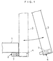
- a door 3 is mounted at a doorway of the guard 1 so as to be opened and closed in an arrow direction between an opened position indicated by a solid line and a closed position indicated by a two-dots-and-dash line.
- a door switch A comprises a switch body 2 and a key unit 4.
- the switch body 2 is attached to an outer edge of the guard 1, has a door key insertion hole 5 therein and includes a contact mechanism, not shown, for turning ON/OFF the power of the machines.
- the key unit 4 is attached to a playing end side of the door 3 and includes a door key 7.
- the door key 7 is pulled out from the key insertion hole 5 in the switch body 2, to thereby turn OFF the contact mechanism of the switch body 2, thus cutting off the power for the machines to stop them in operation.
- the door key 7 is retreated and housed in the key unit 4 by a door key drive mechanism described later. Since this mechanism thus prevents the door key 7 from protruding from the inside of the door 3 when the door 3 is opened, the operator can avoid coming in contact with the door key 7 inadvertently.
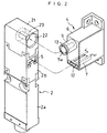
- the switch body 2 comprises a body case 2a and an operation case 2b linked therewith on it.
- the body case 2a has a built-in contact mechanism, not shown, comprised of a switch contact and a plunger for turning ON/OFF this switch contact.
- the operation case 2b has a built-in contact drive mechanism, not shown, comprised of, e.g., a cam for turning ON/OFF the switch contact by driving the plunger of the contact mechanism.
- the key insertion hole 5 into which the door key 7 is inserted.
- the above-mentioned cam in the operation case 2b is rotary-driven in a reverse direction. Then, the plunger in the body case 2a is driven in a direction opposite to the above-mentioned one to thereby turn OFF the switch contact. This cuts off power for the machines and stops them in operation.
- the above-mentioned contact mechanism utilized here is equipped with a forcedly contact opening mechanism for forcedly opening the switch contact.
- a forcedly contact opening mechanism for forcedly opening the switch contact.
- the key unit 4 houses the door key 7 in the unit case 6 and is equipped with a rocking link 8, a push rod 9, and a coil spring 10.
- the unit case 6 is made of a resin and box-shaped with its side opened.
- the unit case 6 has at the rear end thereof an attaching portion 11 for being attached to the door 3, an opening 12 through which the door key 7 is retreated and protruded in its lower part of the front thereof, a boss 13 for guiding the push rod 9 at its upper part of the front thereof, and a rod mounting hole 14 in the bottom of the boss 13.
- the door key 7 is formed by blanking a hard metal sheet such as a stainless steel sheet and by pressing it.
- the door key 7 has a rectangular hole 7a therein through which it is engaged with the above-mentioned contact drive mechanism built in the operation case 2b of the switch body 2, at the base of which is fixed a linkage member 15 by caulking.
- the push rod 9 has a large-diameter head 9a with a spring receiving flange at its front end and is inserted from the front side into the rod mounting hole 14 in the unit case 6 in a state where it is provided with the coil spring 10.
- the rocking link 8 is rotatably supported at its intermediate site by the unit case 6 via a support shaft 16.
- the lower part of the rocking link 8 is interlocked and linked with the linkage member 15 of the door key 7 via an elongated hole 17 and a linkage pin 18.
- the upper part of the rocking link 8 is interlocked and linked with the inner end of the push rod 9 via an elongated hole 19 and a linkage pin 20.
- a distance between the upper side linkage pin 20 and the support shaft 16 is set smaller than a distance between the lower side linkage pin 18 and the support shaft 16. This setting expands retreating and advancing distances of the push rod 9, which are in turn converted into advancing and retreating distances of the door key 7.
- the push rod 9, the coil spring 10, the rocking link 8, etc. make up in combination the door key drive mechanism for protruding the door key 7 from the unit case 6 when a pressure is applied from the outside and retreating it into the unit case 6 when the pressure is deactivated.
- the push rod 9 constitutes a displacing mechanism such that it is retreated and displaced when pressed by the switch body 2 and advanced and displaced when released from the pressing.
- the rocking link 8 is linked between the door key 7 and the push rod 9 for constituting a interlocking mechanism such that it advances the door key 7 out from the unit case 6 as interlocked with retreating of the push rod 9 and retreating the door key 7 into the unit case 6 as interlocked with advancing of the push rod 9.
- the key unit 4 is buried in and mounted on the playing end side of the door 3 in such a manner that the front of the unit case 6 thereof may be roughly flush with the inner surface of the door 3.
- the switch body 2 is linked with a key operation portion 21 at its upper part.
- a recess 22 In the front of the key operation portion 21 is formed a recess 22 having a size permitting the insertion of the boss 13 provided as protruded out the front of the key unit 4.
- a protrusion 23 In the recess 22 is provided a protrusion 23 which can butt against the large-diameter head 9a of the push rod 9.
- the boss 13 in the key unit 4 is inserted into the recess 22 of the key operation portion 21. Accordingly, the door key 7 is held at the above-mentioned retreated position until the protrusion 23 in the recess 22 butts against the large-diameter head 9a of the push rod 9.
- the contact drive mechanism of the operation case 2b drives the contact mechanism of the body case 2a to thereby turn ON the switch contact. Then, the machines enter a power-applied state and start operation.
- the door key 7 can be smoothly inserted into and pulled out from the door key insertion hole 5 even if it is not arranged at the playing end of the door 3 which has a large opening radius in particular, thus being relaxed in restrictions on its installation position.
- the door key 7 can be arranged, for example, near the base end where the operator of the door 3 hardly comes in contact with it.
- the boss 13 protruded out the unit case 6 may be made of hard rubber with an appropriate elasticity so that it may be prevented from being damaged when it comes in contact with other objects.
- the push rod 9 may be provided as buried in the unit case 6. In this case, when the door is open, not only the door key 7 but also the push rod 9 may not come in contact with other objects.
- the protrusion 23 may be made of an elastic material such as hard rubber in case it may protrude to the switch body 2 or the guard 1 to come in contact with the operator or any other object.
- the door key 7 may have a snap action construction, whereby when the push rod 9 is pressed and displaced even slightly by the protrusion 23, the door key 7 may be instantaneously protruded out from the key unit.
- the above-mentioned door key drive mechanism has been described as a mechanical one, it may be such an electrical mechanism that a proximity sensor detects that the door 3 has been completely or mostly closed, and in response to that detection the door key 7 is protruded out from the key unit 4.
- This invention can be applied not only to the rocking opening/closing type but also to sliding opening/closing type of the door 3.
- the key unit 4 may be provided on the fixed side of the guard 1 etc. and the switch body 2, on the side of the door 3.
- the door 3 or the wall surface of the guard 1 may act also as at least part of the unit case 6 of the key unit 4 so that the components in the unit case 6 can be contained in the housing portion formed at the door 3 or the guard 1.
Landscapes
- Engineering & Computer Science (AREA)
- Computer Security & Cryptography (AREA)
- Push-Button Switches (AREA)
- Rotary Switch, Piano Key Switch, And Lever Switch (AREA)
- Mechanisms For Operating Contacts (AREA)
- Keying Circuit Devices (AREA)
- Electrophonic Musical Instruments (AREA)
- Transmitters (AREA)
Abstract
Description
Claims (18)
- A key unit comprising:a unit case;a door key provided in said unit case in such a manner that said door key can be protruded out from and retreated into said unit case; anda door key drive mechanism for, when pressed from the outside, protruding said door key out from said unit case and, when released from said pressing, retreating said door key into said unit case.
- The key unit according to Claim 1, wherein said unit case has an opening in a front thereof, through which said door key can be protruded out from and retreated into said unit case.
- The key unit according to Claim 1, wherein said door key drive mechanism includes:a displacing mechanism which is retreated in displacement when pressed and advanced in displacement when released from pressing; andan interlocking mechanism linked between said door key and said displacing mechanism, for protruding said door key out from and retreating said door key into said key unit as interlocked with displacement of said displacing mechanism.
- The key unit according to Claim 3, wherein said displacing mechanism includes a guide boss provided on a front of said unit case of the key unit, a push rod housed in said guide boss, and a coil spring for energizing said push rod toward said switch body;said push rod is retreated in said unit case when a front end side thereof is pressed by said switch body; andsaid interlocking mechanism is of a configuration having a rocking link for converting a retreating action of said push rod into a protruding action of said door key.
- The key unit according to Claim 4, wherein said rocking link of said interlocking mechanism has a rocking support point at such a position that expands an advancing distance of said door key rather than a retreating distance of said push rod.
- The key unit according to Claim 4, wherein said guide boss of said displacing mechanism is made of a hard elastic material.
- A switch body equipped to a door switch interlocked with a door opening/closing action, said switch body comprising:a body case; andan operation case linked at an upper part of said body case,wherein said body case is provided with a switch contact therein, andwherein said operation case is provided with a contact drive mechanism for switching said switch contact and has a key insertion hole for inserting said switch contact and also has a recess in which a protrusion is provided for pressing a push rod of a key unit.
- A door switch interlocked with a door opening/closing action, said door switch comprising:a switch body; anda key unit which can be separated from said switch body,wherein said switch body has a body case provided with a door key insertion hole therein andwherein said key unit comprises a unit case, a door key arranged in said unit case in such a manner that said door key can be protruded out from and retreated into the unit case, and a door key drive mechanism for, when pressed from the outside, protruding said door key out from said unit case and, when released from said pressing, retreating said door key into said unit case.
- The door switch according to Claim 8, wherein:said switch body is attached on one side of said door or a structure to which the door is mounted;said key unit is attached on the other side of said door or said structure; andsaid door key drive mechanism of said key unit is pressed by said switch body when said door is closed.
- The door switch according to Claim 8, wherein said door key drive mechanism includes:a displacing mechanism which is retreated in displacement when pressed and advanced in displacement when released from pressure; andan interlocking mechanism linked between said door key and said displacing mechanism, for protruding out from or retreating said door key into said key unit as interlocked with displacement in said displacing mechanism.
- The door switch according to Claim 10, wherein:said displacing mechanism includes a guide boss provided on a front of said unit case of the key unit, a push rod housed in said guide boss in such a manner that said push rod can be displaced forward and backward, and a coil spring for energizing said push rod forward;said push rod is retreated in said unit case when a front end side thereof is pressed; andsaid interlocking mechanism includes a rocking link for converting retreating action of said push rod into an advancing action of said door key.
- The door switch according to Claim 11, wherein said rocking link of said interlocking mechanism has a rocking support point at a position that expands an advancing distance of said door key rather than a retreating distance of said push rod.
- The door switch according to Claim 11, wherein said guide boss of said displacing mechanism is made of a hard elastic material.
- The door switch according to Claim 11, wherein said switch body has a recess in which said guide boss of said displacing mechanism can be housed and a protrusion provided in said recess, for pressing said push rod.
- The door switch according to Claim 10, wherein:said displacing mechanism includes a push rod housed in said unit case in such a manner that said push rod can be displaced forward and backward and a coil spring for energizing said push rod forward;when a front end side of said push rod is pressed by said switch body, a rear end side of said push rod is retreated in said unit case; andsaid interlocking mechanism has a rocking link configuration that converts a retreating action of said push rod into an advancing action of said door key.
- The door switch according to Claim 15, wherein said switch body has a protrusion for pressing said push rod.
- The door switch according to Claim 16, wherein said protrusion of said switch body is made of a hard elastic material.
- The door switch according to Claim 8, wherein said unit case of said key unit is formed by part of said door or a structure to which said door is mounted.
Applications Claiming Priority (2)
| Application Number | Priority Date | Filing Date | Title |
|---|---|---|---|
| JP2000139597 | 2000-05-12 | ||
| JP2000139597A JP3941337B2 (en) | 2000-05-12 | 2000-05-12 | Door switch |
Publications (3)
| Publication Number | Publication Date |
|---|---|
| EP1160811A2 true EP1160811A2 (en) | 2001-12-05 |
| EP1160811A3 EP1160811A3 (en) | 2003-02-05 |
| EP1160811B1 EP1160811B1 (en) | 2005-06-29 |
Family
ID=18647019
Family Applications (1)
| Application Number | Title | Priority Date | Filing Date |
|---|---|---|---|
| EP01110460A Expired - Lifetime EP1160811B1 (en) | 2000-05-12 | 2001-04-27 | Key unit and switch body and door switch using the same |
Country Status (6)
| Country | Link |
|---|---|
| US (1) | US6459052B2 (en) |
| EP (1) | EP1160811B1 (en) |
| JP (1) | JP3941337B2 (en) |
| AT (1) | ATE298924T1 (en) |
| CA (1) | CA2347144C (en) |
| DE (1) | DE60111684T2 (en) |
Cited By (5)
| Publication number | Priority date | Publication date | Assignee | Title |
|---|---|---|---|---|
| FR2839191A1 (en) * | 2002-04-25 | 2003-10-31 | Gunnebo Troax Ab | Industrial enclosure door locking having first unit with closure mechanism/simultaneous key formation and second unit receiving elements and function verifying function block fixing mechanism. |
| EP1321090A3 (en) * | 2001-12-19 | 2004-12-22 | Electrolux Home Products Corporation N.V. | Electric household appliance, in particular a dishwashing machine, with an improved access door |
| CN102737900A (en) * | 2011-04-13 | 2012-10-17 | 发那科株式会社 | Anti-collision switch device |
| EP2284432A3 (en) * | 2009-08-14 | 2012-11-07 | K.A. Schmersal Holding GmbH & Co. KG | Device for monitoring the status of a secure facility |
| EP1827650A4 (en) * | 2004-11-30 | 2013-02-20 | Alpha Technologies Corp Ltd | Improved sterilising filter arrangement, apparatus & method |
Families Citing this family (8)
| Publication number | Priority date | Publication date | Assignee | Title |
|---|---|---|---|---|
| US7442888B2 (en) * | 2005-08-22 | 2008-10-28 | Scientific Technologies Incorporated | Safety lock for interlock switch |
| JP4967723B2 (en) * | 2007-03-08 | 2012-07-04 | オムロン株式会社 | Operation key cover |
| DE102012005210B4 (en) | 2012-03-16 | 2022-09-29 | Brühl Safety GmbH | safety fence system |
| USD742840S1 (en) * | 2013-11-13 | 2015-11-10 | Rockwell Automation Technologies, Inc. | Industrial control |
| US10250813B2 (en) * | 2014-09-03 | 2019-04-02 | Fuji Xerox Co., Ltd. | Methods and systems for sharing views |
| US9650142B2 (en) | 2015-02-24 | 2017-05-16 | Panasonic Intellectual Property Management Co., Ltd. | Monitor device driven to move in response to detection by switch |
| WO2020065949A1 (en) * | 2018-09-28 | 2020-04-02 | 株式会社Fuji | Guide-attached safety door |
| JP2023007786A (en) * | 2021-07-02 | 2023-01-19 | パナソニックIpマネジメント株式会社 | Fixture, actuator with fixture, and detection switch |
Family Cites Families (9)
| Publication number | Priority date | Publication date | Assignee | Title |
|---|---|---|---|---|
| US3924085A (en) * | 1974-03-18 | 1975-12-02 | Gen Electric | Safety-start device and circuit controller for domestic appliance |
| GB1503327A (en) * | 1975-10-01 | 1978-03-08 | Unimax Switch Ltd | Electrical switches |
| US4465997A (en) * | 1981-01-26 | 1984-08-14 | Security Network International, Inc. | Exterior mounted door and window alarm switch |
| FR2655185B1 (en) * | 1989-11-27 | 1992-02-21 | Telemecanique | SAFETY SWITCHING APPARATUS OPERATING BY INSERTING AND EXTRACTING A KEY. |
| FR2655183B1 (en) * | 1989-11-27 | 1992-02-21 | Telemecanique | KEY SECURITY SWITCHING APPARATUS. |
| DE4436199C1 (en) * | 1994-10-11 | 1995-12-14 | Bernstein Hans Spezialfabrik | Radius actuator e.g for machinery safety switches |
| DE29516230U1 (en) * | 1995-10-13 | 1995-12-07 | Hans Bernstein, Spezialfabrik für Schaltkontakte GmbH & Co, 32457 Porta Westfalica | Radius actuator for safety switches |
| DE29801192U1 (en) * | 1998-01-26 | 1998-08-20 | Hans Bernstein Spezialfabrik für Schaltkontakte GmbH & Co, 32457 Porta Westfalica | Radius actuator for safety switches |
| US6268574B1 (en) * | 1999-04-29 | 2001-07-31 | Rudolph R. Edens | Electrical and pneumatic lock-out device |
-
2000
- 2000-05-12 JP JP2000139597A patent/JP3941337B2/en not_active Expired - Lifetime
-
2001
- 2001-04-27 DE DE60111684T patent/DE60111684T2/en not_active Expired - Lifetime
- 2001-04-27 AT AT01110460T patent/ATE298924T1/en not_active IP Right Cessation
- 2001-04-27 EP EP01110460A patent/EP1160811B1/en not_active Expired - Lifetime
- 2001-05-09 US US09/851,413 patent/US6459052B2/en not_active Expired - Fee Related
- 2001-05-09 CA CA002347144A patent/CA2347144C/en not_active Expired - Fee Related
Cited By (6)
| Publication number | Priority date | Publication date | Assignee | Title |
|---|---|---|---|---|
| EP1321090A3 (en) * | 2001-12-19 | 2004-12-22 | Electrolux Home Products Corporation N.V. | Electric household appliance, in particular a dishwashing machine, with an improved access door |
| FR2839191A1 (en) * | 2002-04-25 | 2003-10-31 | Gunnebo Troax Ab | Industrial enclosure door locking having first unit with closure mechanism/simultaneous key formation and second unit receiving elements and function verifying function block fixing mechanism. |
| EP1827650A4 (en) * | 2004-11-30 | 2013-02-20 | Alpha Technologies Corp Ltd | Improved sterilising filter arrangement, apparatus & method |
| EP2284432A3 (en) * | 2009-08-14 | 2012-11-07 | K.A. Schmersal Holding GmbH & Co. KG | Device for monitoring the status of a secure facility |
| CN102737900A (en) * | 2011-04-13 | 2012-10-17 | 发那科株式会社 | Anti-collision switch device |
| CN102737900B (en) * | 2011-04-13 | 2013-11-06 | 发那科株式会社 | Anti-collision switch device |
Also Published As
| Publication number | Publication date |
|---|---|
| DE60111684D1 (en) | 2005-08-04 |
| CA2347144C (en) | 2005-04-12 |
| ATE298924T1 (en) | 2005-07-15 |
| EP1160811A3 (en) | 2003-02-05 |
| US20020006741A1 (en) | 2002-01-17 |
| EP1160811B1 (en) | 2005-06-29 |
| JP3941337B2 (en) | 2007-07-04 |
| US6459052B2 (en) | 2002-10-01 |
| DE60111684T2 (en) | 2006-05-18 |
| JP2001319549A (en) | 2001-11-16 |
| CA2347144A1 (en) | 2001-11-12 |
Similar Documents
| Publication | Publication Date | Title |
|---|---|---|
| US6459052B2 (en) | Key unit and switch body and door switch using the same | |
| EP1879093A2 (en) | Improved knob assembly for operating the switch of a radio | |
| US8403378B2 (en) | Door latch device for a vehicle | |
| EP1134765B1 (en) | Lock switch apparatus | |
| US11581154B2 (en) | Battery lock out for power tool | |
| US7345252B2 (en) | Key switch | |
| AU2022201520B2 (en) | Fastening tool | |
| KR20040078642A (en) | Electrical working machine | |
| JP2001056176A (en) | Door opening unit for storage | |
| JP4965418B2 (en) | Door lock mechanism | |
| TW357208B (en) | Appliance interlocking mechanism and appliance including the interlocking mechanism | |
| JPWO2009031224A1 (en) | Switch device | |
| JPH10247448A (en) | Circuit breaker handle operating device | |
| JP4978967B2 (en) | Locking device | |
| JP4582788B2 (en) | Locking device | |
| JP4769100B2 (en) | Safety switch | |
| JP4579008B2 (en) | Power tool storage box | |
| US20250046542A1 (en) | Trigger switch | |
| CN216980403U (en) | Switch module for electric tool and electric tool | |
| JPH09259711A (en) | Double circuit breaker prevention device | |
| JP2004055434A (en) | Push button switch | |
| JP3955800B2 (en) | Switch device | |
| EP1132550A1 (en) | Security system for motor vehicle wing | |
| JP4396480B2 (en) | Key switch | |
| CN1784531A (en) | Lock |
Legal Events
| Date | Code | Title | Description |
|---|---|---|---|
| PUAI | Public reference made under article 153(3) epc to a published international application that has entered the european phase |
Free format text: ORIGINAL CODE: 0009012 |
|
| 17P | Request for examination filed |
Effective date: 20010530 |
|
| AK | Designated contracting states |
Kind code of ref document: A2 Designated state(s): AT BE CH CY DE DK ES FI FR GB GR IE IT LI LU MC NL PT SE TR |
|
| AX | Request for extension of the european patent |
Free format text: AL;LT;LV;MK;RO;SI |
|
| PUAL | Search report despatched |
Free format text: ORIGINAL CODE: 0009013 |
|
| RIC1 | Information provided on ipc code assigned before grant |
Ipc: 7H 01H 27/00 B Ipc: 7H 01H 3/16 A |
|
| AK | Designated contracting states |
Designated state(s): AT BE CH CY DE DK ES FI FR GB GR IE IT LI LU MC NL PT SE TR |
|
| AX | Request for extension of the european patent |
Extension state: AL LT LV MK RO SI |
|
| 17Q | First examination report despatched |
Effective date: 20030820 |
|
| AKX | Designation fees paid |
Designated state(s): AT BE CH CY DE DK ES FI FR GB GR IE IT LI LU MC NL PT SE TR |
|
| GRAP | Despatch of communication of intention to grant a patent |
Free format text: ORIGINAL CODE: EPIDOSNIGR1 |
|
| GRAS | Grant fee paid |
Free format text: ORIGINAL CODE: EPIDOSNIGR3 |
|
| GRAA | (expected) grant |
Free format text: ORIGINAL CODE: 0009210 |
|
| AK | Designated contracting states |
Kind code of ref document: B1 Designated state(s): AT BE CH CY DE DK ES FI FR GB GR IE IT LI LU MC NL PT SE TR |
|
| PG25 | Lapsed in a contracting state [announced via postgrant information from national office to epo] |
Ref country code: FI Free format text: LAPSE BECAUSE OF FAILURE TO SUBMIT A TRANSLATION OF THE DESCRIPTION OR TO PAY THE FEE WITHIN THE PRESCRIBED TIME-LIMIT Effective date: 20050629 Ref country code: LI Free format text: LAPSE BECAUSE OF FAILURE TO SUBMIT A TRANSLATION OF THE DESCRIPTION OR TO PAY THE FEE WITHIN THE PRESCRIBED TIME-LIMIT Effective date: 20050629 Ref country code: BE Free format text: LAPSE BECAUSE OF FAILURE TO SUBMIT A TRANSLATION OF THE DESCRIPTION OR TO PAY THE FEE WITHIN THE PRESCRIBED TIME-LIMIT Effective date: 20050629 Ref country code: CH Free format text: LAPSE BECAUSE OF FAILURE TO SUBMIT A TRANSLATION OF THE DESCRIPTION OR TO PAY THE FEE WITHIN THE PRESCRIBED TIME-LIMIT Effective date: 20050629 Ref country code: NL Free format text: LAPSE BECAUSE OF FAILURE TO SUBMIT A TRANSLATION OF THE DESCRIPTION OR TO PAY THE FEE WITHIN THE PRESCRIBED TIME-LIMIT Effective date: 20050629 Ref country code: AT Free format text: LAPSE BECAUSE OF FAILURE TO SUBMIT A TRANSLATION OF THE DESCRIPTION OR TO PAY THE FEE WITHIN THE PRESCRIBED TIME-LIMIT Effective date: 20050629 |
|
| REG | Reference to a national code |
Ref country code: GB Ref legal event code: FG4D |
|
| REG | Reference to a national code |
Ref country code: CH Ref legal event code: EP |
|
| REF | Corresponds to: |
Ref document number: 60111684 Country of ref document: DE Date of ref document: 20050804 Kind code of ref document: P |
|
| REG | Reference to a national code |
Ref country code: IE Ref legal event code: FG4D |
|
| PG25 | Lapsed in a contracting state [announced via postgrant information from national office to epo] |
Ref country code: GR Free format text: LAPSE BECAUSE OF FAILURE TO SUBMIT A TRANSLATION OF THE DESCRIPTION OR TO PAY THE FEE WITHIN THE PRESCRIBED TIME-LIMIT Effective date: 20050929 Ref country code: DK Free format text: LAPSE BECAUSE OF FAILURE TO SUBMIT A TRANSLATION OF THE DESCRIPTION OR TO PAY THE FEE WITHIN THE PRESCRIBED TIME-LIMIT Effective date: 20050929 Ref country code: SE Free format text: LAPSE BECAUSE OF FAILURE TO SUBMIT A TRANSLATION OF THE DESCRIPTION OR TO PAY THE FEE WITHIN THE PRESCRIBED TIME-LIMIT Effective date: 20050929 |
|
| PG25 | Lapsed in a contracting state [announced via postgrant information from national office to epo] |
Ref country code: ES Free format text: LAPSE BECAUSE OF FAILURE TO SUBMIT A TRANSLATION OF THE DESCRIPTION OR TO PAY THE FEE WITHIN THE PRESCRIBED TIME-LIMIT Effective date: 20051010 |
|
| NLV1 | Nl: lapsed or annulled due to failure to fulfill the requirements of art. 29p and 29m of the patents act | ||
| PG25 | Lapsed in a contracting state [announced via postgrant information from national office to epo] |
Ref country code: PT Free format text: LAPSE BECAUSE OF FAILURE TO SUBMIT A TRANSLATION OF THE DESCRIPTION OR TO PAY THE FEE WITHIN THE PRESCRIBED TIME-LIMIT Effective date: 20051207 |
|
| REG | Reference to a national code |
Ref country code: CH Ref legal event code: PL |
|
| ET | Fr: translation filed | ||
| PG25 | Lapsed in a contracting state [announced via postgrant information from national office to epo] |
Ref country code: IE Free format text: LAPSE BECAUSE OF NON-PAYMENT OF DUE FEES Effective date: 20060427 |
|
| PG25 | Lapsed in a contracting state [announced via postgrant information from national office to epo] |
Ref country code: MC Free format text: LAPSE BECAUSE OF NON-PAYMENT OF DUE FEES Effective date: 20060430 |
|
| PLBE | No opposition filed within time limit |
Free format text: ORIGINAL CODE: 0009261 |
|
| STAA | Information on the status of an ep patent application or granted ep patent |
Free format text: STATUS: NO OPPOSITION FILED WITHIN TIME LIMIT |
|
| 26N | No opposition filed |
Effective date: 20060330 |
|
| REG | Reference to a national code |
Ref country code: IE Ref legal event code: MM4A |
|
| PG25 | Lapsed in a contracting state [announced via postgrant information from national office to epo] |
Ref country code: LU Free format text: LAPSE BECAUSE OF NON-PAYMENT OF DUE FEES Effective date: 20060427 Ref country code: TR Free format text: LAPSE BECAUSE OF FAILURE TO SUBMIT A TRANSLATION OF THE DESCRIPTION OR TO PAY THE FEE WITHIN THE PRESCRIBED TIME-LIMIT Effective date: 20050629 |
|
| PG25 | Lapsed in a contracting state [announced via postgrant information from national office to epo] |
Ref country code: CY Free format text: LAPSE BECAUSE OF FAILURE TO SUBMIT A TRANSLATION OF THE DESCRIPTION OR TO PAY THE FEE WITHIN THE PRESCRIBED TIME-LIMIT Effective date: 20050629 |
|
| PGFP | Annual fee paid to national office [announced via postgrant information from national office to epo] |
Ref country code: FR Payment date: 20100421 Year of fee payment: 10 |
|
| PGFP | Annual fee paid to national office [announced via postgrant information from national office to epo] |
Ref country code: DE Payment date: 20100430 Year of fee payment: 10 Ref country code: IT Payment date: 20100426 Year of fee payment: 10 |
|
| PGFP | Annual fee paid to national office [announced via postgrant information from national office to epo] |
Ref country code: GB Payment date: 20100413 Year of fee payment: 10 |
|
| REG | Reference to a national code |
Ref country code: DE Ref legal event code: R119 Ref document number: 60111684 Country of ref document: DE |
|
| REG | Reference to a national code |
Ref country code: DE Ref legal event code: R119 Ref document number: 60111684 Country of ref document: DE |
|
| GBPC | Gb: european patent ceased through non-payment of renewal fee |
Effective date: 20110427 |
|
| REG | Reference to a national code |
Ref country code: FR Ref legal event code: ST Effective date: 20111230 |
|
| PG25 | Lapsed in a contracting state [announced via postgrant information from national office to epo] |
Ref country code: FR Free format text: LAPSE BECAUSE OF NON-PAYMENT OF DUE FEES Effective date: 20110502 |
|
| PG25 | Lapsed in a contracting state [announced via postgrant information from national office to epo] |
Ref country code: IT Free format text: LAPSE BECAUSE OF NON-PAYMENT OF DUE FEES Effective date: 20110427 Ref country code: GB Free format text: LAPSE BECAUSE OF NON-PAYMENT OF DUE FEES Effective date: 20110427 |
|
| REG | Reference to a national code |
Ref country code: DE Ref legal event code: R082 Ref document number: 60111684 Country of ref document: DE Representative=s name: KILIAN KILIAN & PARTNER MBB PATENTANWAELTE, DE Ref country code: DE Ref legal event code: R082 Ref document number: 60111684 Country of ref document: DE Representative=s name: KILIAN KILIAN & PARTNER, DE |
|
| PG25 | Lapsed in a contracting state [announced via postgrant information from national office to epo] |
Ref country code: DE Free format text: LAPSE BECAUSE OF NON-PAYMENT OF DUE FEES Effective date: 20111031 |