EP1160804A2 - Preparation of rare earth permanent magnets - Google Patents
Preparation of rare earth permanent magnets Download PDFInfo
- Publication number
- EP1160804A2 EP1160804A2 EP01304823A EP01304823A EP1160804A2 EP 1160804 A2 EP1160804 A2 EP 1160804A2 EP 01304823 A EP01304823 A EP 01304823A EP 01304823 A EP01304823 A EP 01304823A EP 1160804 A2 EP1160804 A2 EP 1160804A2
- Authority
- EP
- European Patent Office
- Prior art keywords
- weight
- rare earth
- magnet
- alloy
- neodymium
- Prior art date
- Legal status (The legal status is an assumption and is not a legal conclusion. Google has not performed a legal analysis and makes no representation as to the accuracy of the status listed.)
- Granted
Links
Images

Classifications
-
- H—ELECTRICITY
- H01—ELECTRIC ELEMENTS
- H01F—MAGNETS; INDUCTANCES; TRANSFORMERS; SELECTION OF MATERIALS FOR THEIR MAGNETIC PROPERTIES
- H01F1/00—Magnets or magnetic bodies characterised by the magnetic materials therefor; Selection of materials for their magnetic properties
- H01F1/01—Magnets or magnetic bodies characterised by the magnetic materials therefor; Selection of materials for their magnetic properties of inorganic materials
- H01F1/03—Magnets or magnetic bodies characterised by the magnetic materials therefor; Selection of materials for their magnetic properties of inorganic materials characterised by their coercivity
- H01F1/032—Magnets or magnetic bodies characterised by the magnetic materials therefor; Selection of materials for their magnetic properties of inorganic materials characterised by their coercivity of hard-magnetic materials
- H01F1/04—Magnets or magnetic bodies characterised by the magnetic materials therefor; Selection of materials for their magnetic properties of inorganic materials characterised by their coercivity of hard-magnetic materials metals or alloys
- H01F1/047—Alloys characterised by their composition
- H01F1/053—Alloys characterised by their composition containing rare earth metals
- H01F1/055—Alloys characterised by their composition containing rare earth metals and magnetic transition metals, e.g. SmCo5
- H01F1/057—Alloys characterised by their composition containing rare earth metals and magnetic transition metals, e.g. SmCo5 and IIIa elements, e.g. Nd2Fe14B
- H01F1/0571—Alloys characterised by their composition containing rare earth metals and magnetic transition metals, e.g. SmCo5 and IIIa elements, e.g. Nd2Fe14B in the form of particles, e.g. rapid quenched powders or ribbon flakes
- H01F1/0575—Alloys characterised by their composition containing rare earth metals and magnetic transition metals, e.g. SmCo5 and IIIa elements, e.g. Nd2Fe14B in the form of particles, e.g. rapid quenched powders or ribbon flakes pressed, sintered or bonded together
- H01F1/0577—Alloys characterised by their composition containing rare earth metals and magnetic transition metals, e.g. SmCo5 and IIIa elements, e.g. Nd2Fe14B in the form of particles, e.g. rapid quenched powders or ribbon flakes pressed, sintered or bonded together sintered
-
- H—ELECTRICITY
- H01—ELECTRIC ELEMENTS
- H01F—MAGNETS; INDUCTANCES; TRANSFORMERS; SELECTION OF MATERIALS FOR THEIR MAGNETIC PROPERTIES
- H01F41/00—Apparatus or processes specially adapted for manufacturing or assembling magnets, inductances or transformers; Apparatus or processes specially adapted for manufacturing materials characterised by their magnetic properties
- H01F41/02—Apparatus or processes specially adapted for manufacturing or assembling magnets, inductances or transformers; Apparatus or processes specially adapted for manufacturing materials characterised by their magnetic properties for manufacturing cores, coils, or magnets
- H01F41/0253—Apparatus or processes specially adapted for manufacturing or assembling magnets, inductances or transformers; Apparatus or processes specially adapted for manufacturing materials characterised by their magnetic properties for manufacturing cores, coils, or magnets for manufacturing permanent magnets
- H01F41/026—Apparatus or processes specially adapted for manufacturing or assembling magnets, inductances or transformers; Apparatus or processes specially adapted for manufacturing materials characterised by their magnetic properties for manufacturing cores, coils, or magnets for manufacturing permanent magnets protecting methods against environmental influences, e.g. oxygen, by surface treatment
Definitions
- This invention relates to a method for preparing rare earth permanent magnets to be exposed to refrigerants and/or lubricants for an extended period of time, and especially useful in high efficiency motors.
- rare earth permanent magnets are utilized in many areas of electric and electronic equipment.
- the production of rare earth permanent magnets is rapidly increasing in these years.
- rare earth permanent magnets are advantageous in that neodymium as the predominant element is present in more plenty than samarium, the raw material cost is low because of the relatively low content of cobalt, and their magnetic properties substantially surpass those of rare earth cobalt magnets.
- the rare earth permanent magnets now find use not only in small-size magnetic circuits where rare earth cobalt magnets have been used, but also in areas where hard ferrite and electromagnets have been used.
- transition from prior art induction motors and synchronous motors using ferrite magnets to DC brushless motors using rare earth magnets is in progress for the purpose of increasing energy efficiency for reducing the power consumption.
- R-Fe-B permanent magnets have the drawback that they are readily oxidized in humid air within a short time since they contain rare earth elements and iron as main components.
- R-Fe-B magnets When R-Fe-B magnets are incorporated in magnetic circuits, oxidative corrosion can reduce the output of magnetic circuits and generate rust with which the surrounding equipment is contaminated. Therefore, rare earth magnets are generally surface treated prior to use.
- the surface treatment on rare earth magnets includes electroplating, electroless plating, aluminum-ion plating, and various coating techniques.
- the rare earth permanent magnets are required to be corrosion resistant under high pressure and high temperature conditions in the refrigerant and refrigerating machine oil mixed system.
- JP-A 11-150930 discloses the use of non-surface-treated rare earth magnet as the core of the rotor in a refrigerating compressor.
- HFC refrigerant with an ether or ester base refrigerating machine oil can detract from the magnetic properties of the magnet incorporated in the system during a long term of operation at high temperature.
- the Al-ion plating technique is expensive and industrially inexpedient. Coating is unacceptable because of reaction with solvents and oil.
- the plating technique has the problem of instability at high temperature, as demonstrated by stripping of a plated coating at the temperature of shrinkage fit between the rotor and the shaft. It is difficult to industrially apply the plating surface treatment to large size magnets, yielding many undesirably plated parts.
- rare earth permanent magnets for use in high efficiency motors are exposed to the refrigerants and/or lubricants at high temperature and high pressure for an extended period of time and will detract from their magnetic properties due to reaction or corrosion therewith.
- the invention provides a method for preparing a rare earth permanent magnet, comprising the steps of casting an alloy based on R, T and B, wherein R is neodymium or a combination of neodymium with one or more rare earth elements, T is iron or a mixture of iron and cobalt, and B is boron, said alloy consisting essentially of 17 to 33.5% by weight of neodymium, 26.8 to 33.5% by weight of the entire R (inclusive of neodymium), 0.78 to 1.25% by weight of B, 0.05 to 3.5% by weight of at least one element selected from the group consisting of Ni, Ga, Zr, Nb, Hf, Ta, Mn, Sn, Mo, Zn, Pb, Sb, Al, Si, V, Cr, Ti, Cu, Ca and Mg, the balance being T and incidental impurities; crushing the alloy in an oxygen-free atmosphere of argon, nitrogen or vacuum, followed by comminution, compacting under a
- the rare earth permanent magnet produced by the above method is suitable for exposure to a refrigerant and/or lubricant for an extended period of time.
- the invention provides a method for preparing a rare earth permanent magnet, comprising the steps of furnishing a mother alloy based on R, T and B, wherein R is neodymium or a combination of neodymium with one or more rare earth elements, T is iron or a mixture of iron and cobalt, and B is boron, said mother alloy consisting essentially of 17 to 33.5% by weight of neodymium, 26.8 to 33.5% by weight of the entire R (inclusive of neodymium), 0.78 to 1.25% by weight of B, 0.05 to 3.5% by weight of at least one element selected from the group consisting of Ni, Ga, Zr, Nb, Hf, Ta, Mn, Sn, Mo, Zn, Pb, Sb, Al, Si, V, Cr, Ti, Cu, Ca and Mg, the balance being T and incidental impurities, and an auxiliary alloy consisting essentially of 28 to 70% by weight of R' wherein R' is at least one
- a rare earth magnet produced by the above method typically is suitable for exposure to a refrigerant and/or lubricant for an extended period of time.
- corrosion resistance e.g. of the above-specified composition of a rare earth magnet may be improved by heat treating the magnet, which has been cut and/or polished to give a surface finish, in an argon, nitrogen or low-pressure vacuum atmosphere having an oxygen partial pressure of 10 -6 to 10° torr for 10 minutes to 10 hours.
- this heat treatment is at a temperature of 200 to 1,100°C.
- rare earth magnets which are used in various high efficiency motors (complying with the revised energy saving regulation enacted in Japan) and exposed to HFC alternative refrigerant and/or lubricant under operating conditions for an extended period of time.
- the invention provides a rare earth permanent magnet obtainable according to any of the method aspects of the invention.
- the invention provides a use of a magnet according to the above aspect is a high efficiency motor.
- an alloy based on R, T and B is first cast.
- R is neodymium or a combination of neodymium with one or more rare earth elements
- T is iron or a mixture of iron and cobalt
- B is boron.
- the alloy consists essentially of 17 to 33.5% by weight of neodymium, 26.8 to 33.5% by weight of the entire R (inclusive of neodymium), 0.78 to 1.25% by weight of B, 0.05 to 3.5% by weight of at least one element selected from the group consisting of Ni, Ga, Zr, Nb, Hf, Ta, Mn, Sn, Mo, Zn, Pb, Sb, Al, Si, V, Cr, Ti, Cu, Ca and Mg, the balance being T and incidental impurities.
- R in the R-Fe-B permanent magnet accounts for 26.8 to 33.5% by weight of the composition.
- R is neodymium or a combination of neodymium with another rare earth element which is typically selected from among Y, La, Ce, Pr, Pm, Sm, Gd, Tb, Dy, Ho, Er, Lu, and Yb and mixtures of any.
- R is neodymium or a combination of neodymium with at least one of Ce, La, Pr, Dy, and Tb. While R should essentially contain neodymium, the content of neodymium in the alloy is 17 to 33.5% by weight, preferably 17 to 33% by weight.
- B is contained in the range of 0.78 to 1.25% by weight.
- T the amount of which is the balance is Fe or Fe and Co.
- Fe is contained in the range of 50 to 70% by weight in the alloy. Partial replacement of iron by cobalt can improve the temperature characteristics.
- the content of cobalt (Co / (Co + Fe)) is preferably 20% by weight or less, more preferably 0.1 to 15% by weight based on the total weight of iron and cobalt. Inclusion of more than 20% by weight of cobalt may result in a reduced coercive force and an increased cost.
- the alloy further contains one or more elements selected from the group consisting of Ni, Ga, Zr, Nb, Hf, Ta, Mn, Sn, Mo, Zn, Pb, Sb, Al, Si, V, Cr, Ti, Cu, Ca and Mg.
- the alloy of the above-described composition can be obtained by melting a corresponding material at or above the melting point of the alloy and casting the material by a die casting, roll quenching, or atomizing technique.
- the preferred casting techniques are die casting and chill roll techniques.
- the alloy is crushed in an oxygen-free atmosphere of argon, nitrogen or vacuum, typically by hydriding or using a Brown mill, pin mill, jaw crasher or the like. It is then comminuted, preferably to a mean particle size of about 1 to 30 ⁇ m.
- the resulting powder is compacted and oriented under a magnetic field or compacted in the absence of a magnetic field.
- the compact is sintered, solid solution treated and aged to form a bulk body.
- the bulk body is machined and polished, thereby yielding a permanent magnet of the desired practical shape.
- the rare earth magnet is obtained by furnishing a mother alloy based on R, T and B, wherein R is neodymium or a combination of neodymium with one or more rare earth elements, T is iron or a mixture of iron and cobalt, and B is boron, the mother alloy consisting essentially of 17 to 33.5%, especially 17 to 33% by weight of neodymium, 26.8 to 33.5% by weight of the entire R (inclusive of neodymium), 0.78 to 1.25% by weight of B, 0.05 to 3.5% by weight of one or more elements selected from the group consisting of Ni, Ga, Zr, Nb, Hf, Ta, Mn, Sn, Mo, Zn, Pb, Sb, Al, Si, V, Cr, Ti, Cu, Ca and Mg, the balance being T and incidental impurities, and an auxiliary alloy consisting essentially of 28 to 70% by weight of R' wherein R' is a rare earth element or a mixture of two or more rare earth elements
- R' is one or more elements selected from among Y, La, Ce, Pr, Nd, Pm, Sm, Gd, Tb, Dy, Ho, Er, Lu and Yb, and preferably one or more elements selected from among Ce, La, Nd, Pr, Dy and Tb.
- the preferred content of B is 0.78 to 1.25% by weight.
- the preferred content of cobalt is 10 to 60%, especially 10 to 40% by weight based on the auxiliary alloy, preferably with iron making up the balance.
- the permanent magnet (sintered magnet) thus obtained in either embodiment should have an oxygen concentration of up to 0.8% by weight, and magnetic properties including a residual flux density Br of 12.0 kG to 15.2 kG and a coercive force iHc of 9 kOe to 35 kOe. It is preferred for improved magnetic properties including coercivity that the sintered magnet have an oxygen concentration of 0.05 to 0.8% by weight and a carbon concentration of 0.03 to 0.10% by weight.
- the permanent magnet is then heat treated for thereby improving corrosion resistance.
- the heat treatment is preferably at a temperature of 200 to 1,100°C, more preferably 300 to 600°C, and even more preferably 450 to 550°C. Too high a heat treatment temperature may deteriorate magnetic properties whereas too low a heat treatment temperature may fail to improve the durability against lubricants and/or refrigerants.
- the atmosphere of heat treatment is an argon, nitrogen or low-pressure vacuum atmosphere having an oxygen partial pressure of 10 -6 to 10 0 torr, preferably 10 -5 to 10 -4 torr.
- the duration of heat treatment is from 10 minutes to 10 hours, preferably from 10 minutes to 6 hours and more preferably from 30 minutes to 3 hours.
- the R-Fe-B permanent magnet may be cooled at a rate of 10 to 2,000°C/min. If desired, heat treatment may be effected in plural stages.
- the heat treatment forms suboxides on the magnet surface, thereby yielding a highly corrosion resistant rare earth permanent magnet suitable for use in high efficiency motors.
- the magnet obtained by the invention is characterized by exhibiting corrosion resistance to HFC alternative refrigerants (e.g., R410A, R134a and R125), HCFC refrigerants (e.g., R22 and R32) and lubricants (e.g., refrigerating machine oil such as mineral oil, ester oil or ether oil).
- HFC alternative refrigerants e.g., R410A, R134a and R125
- HCFC refrigerants e.g., R22 and R32
- lubricants e.g., refrigerating machine oil such as mineral oil, ester oil or ether oil.
- an ingot having the composition of 32Nd-1.2B-59.8Fe-7Co in weight ratio was cast.
- the ingot was crushed by a jaw crusher and comminuted by a jet mill using nitrogen gas, obtaining particles having a mean particle size of 3.5 ⁇ m.
- the powder was placed in a mold and compacted therein under a pressure of 1.0 ton/cm 2 while a magnetic field of 10 kOe was applied across the mold.
- the compact was sintered in vacuum at 1,100°C for two hours and aged at 550°C for one hour, obtaining a permanent magnet. From the permanent magnet, a magnet plate dimensioned 5.9 mm x 5.9 mm x 1.2 mm thick was cut out.
- a cap bolt type pressure vessel having a volume of 200 ml (TPR N2 type by Taiatsu Glass Kogyo K.K.), 20 g of a commercially available ester base refrigerating machine oil or ether base refrigerating machine oil was weighed, and the specimen of R-Fe-B permanent magnet was placed. After the pressure vessel was closed, it was cooled with a dry ice/ethanol freezing mixture. HFC alternative in the liquid state as the refrigerant was injected into the vessel. The amount of HFC alternative introduced was determined from the weight gain of the overall pressure vessel. The HFC alternative feed was controlled so as to give a HFC alternative weight of 20 g, that is, to set the weight ratio of refrigerant to refrigerating machine oil at 1:1.
- Example 1 An R-Fe-B permanent magnet was prepared as in Example 1 except that the heat treatment was omitted. Using this magnet as a test specimen, a similar tube test was carried out. The results are shown in FIG. 1 and Table 1.
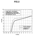
- Example 2 An R-Fe-B permanent magnet was prepared as in Example 1 except that the heat treatment was effected in air at 400°C for 30 minutes. Using this magnet as a test specimen, a similar tube test was carried out. The results are shown in FIG. 2 and Table 1.
- the samples of this example are low oxygen concentration alloys prepared by conducting crushing to sintering steps in an oxygen-blocked atmosphere.
- the starting materials Nd, Pr, Dy, Tb, electrolytic iron, Co, ferroboron, Al, Cu and optionally ferrozirconium or ferrohafnium were formulated to the composition shown in Table 2, following which the respective alloys were prepared by a double roll quenching process.
- the alloys were hydrogenated in a 1.5 ⁇ 0.5 kgf/cm 2 hydrogen atmosphere, followed by dehydrogenation at 600°C for 5 hours in a ⁇ 10 -2 torr vacuum.
- Each of the alloys obtained following hydrogenation and dehydrogenation was in the form of a coarse powder having a particle size of several hundred microns.
- the coarse powders were each mixed with 0.06 wt% of lauric acid as a lubricating agent in a V-type mixer, and comminuted to a mean particle size of about 3 ⁇ m under a nitrogen stream in a jet mill.
- the resulting fine powders were filled into the die of a press, oriented in a 13 kOe magnetic field, and compacted under a pressure of 1.2 ton/cm 2 applied perpendicular to the magnetic field.
- the powder compacts were sintered at 1,050°C for 2 hours in argon, cooled, and heat treated at 500°C for 2 hours in argon, yielding permanent magnet materials of the respective compositions.
- R-Fe-B base permanent magnet materials had a carbon content of 0.061 to 0.073 wt% and an oxygen content of 0.105 to 0.186 wt%. Their magnetic properties are shown in Table 2.
- the starting materials Nd, Dy, electrolytic iron, Co, ferroboron, Al, and Cu were formulated to the composition shown in Table 3, following which the formulations were induction melted and cast in a water-cooled copper mold to give ingots of the respective compositions.
- the cast ingots were roughly ground in a Brown mill.
- the resulting coarse powders were each mixed with 0.08 wt% of stearic acid as a lubricating agent in a V-type mixer, and comminuted to a mean particle size of about 3 ⁇ m under a nitrogen stream in a jet mill.
- the resulting fine powders were filled into the die of a press, oriented in a 12 kOe magnetic field, and compacted under a pressure of 1.5 ton/cm 2 applied perpendicular to the magnetic field.
- the powder compacts were sintered at 1,080°C for 2 hours in a ⁇ 10 -4 torr vacuum, cooled, and heat treated at 600°C for 1 hour in a ⁇ 10 -2 torr vacuum, yielding permanent magnet materials of the respective compositions.
- These R-Fe-B base permanent magnet materials had a carbon content of 0.081 to 0.092 wt% and an oxygen content of 0.058 to 0.071 wt%.
- Their magnetic properties are shown in Table 3. Sample No.
- This example attempted to achieve even higher magnetic properties by applying a two alloy process to the invention.
- the samples of this example are low oxygen concentration alloys prepared by conducting crushing to sintering steps in an oxygen-blocked atmosphere.
- the mother alloy was fabricated by single roll quenching, hydrogenated in a hydrogen atmosphere at 0.5 to 2.0 kgf/cm 2 , then semi-dehydrogenated in a ⁇ 10 -2 torr vacuum and at 500°C for 5 hours.
- the auxiliary alloy was induction melted, then cast in a water-cooled copper mold, giving a cast ingot.
- the powder compacts were sintered at 1,040°C for 2 hours under a vacuum of ⁇ 10 -4 torr, cooled, then heat treated at 500°C for 1 hour in an argon atmosphere, yielding permanent magnet materials of the respective compositions.
- These R-Fe-B base permanent magnet materials had a carbon content of 0.052 to 0.063 wt% and an oxygen content of 0.085 to 0.105 wt%.
- Their magnetic properties are shown in Table 4.
- the powder compacts were sintered at temperatures ranging from 1,020°C to 1,100°C in 10°C increments for 2 hours under a vacuum of ⁇ 10 -4 torr, cooled, then heat treated at 500°C for 1 hour in an argon atmosphere of ⁇ 10 -2 torr, yielding permanent magnet materials of the respective compositions.
- These R-Fe-B base permanent magnet materials had a carbon content of 0.063 to 0.075 wt% and an oxygen content of 0.328 to 0.457 wt%.
- Their magnetic properties are shown in Table 5.
- the powder compacts were sintered at temperatures ranging from 1,020°C to 1,100°C in 10°C increments for 2 hours under a ⁇ 10 -4 torr vacuum, cooled, then heat treated at 500°C for 1 hour under a ⁇ 10 -2 torr vacuum, yielding permanent magnet materials of the respective compositions.
- These R-Fe-B base permanent magnet. materials had a carbon content of 0.082 to 0.093 wt% and an oxygen content of 0.115 to 0.205 wt%.
- Their magnetic properties are shown in Table 6. Sample No. Components (wt%) Br (kG) iHc (kOe) Nd Pr Dy Tb Fe Co B Al Cu Zr Hf 13 Mother 29.0 0.0 0.0 0.0 bal.
- the invention is advantageously applicable to any permanent magnet sample independent of whether the auxiliary alloy was fabricated by induction melting, casting in a water-cooled mold, hydrogenation and semi-dehydrogenation, or by single or double chill roll quenching, hydrogenation and semi-dehydrogenation, or by single or double roll quenching and crushing in a Brown mill or the like.
- an R-Fe-B permanent magnet as appropriately processed is further heat treated to form a protective film on the surface whereby a highly oil resistant sintered permanent magnet having corrosion resistance and hydrogen barrier property even in a high pressure with hot environment of refrigerant and lubricant can be readily manufactured at a low cost.
- the invention is of great worth in the industry.
Landscapes
- Engineering & Computer Science (AREA)
- Power Engineering (AREA)
- Chemical & Material Sciences (AREA)
- Crystallography & Structural Chemistry (AREA)
- Inorganic Chemistry (AREA)
- Environmental & Geological Engineering (AREA)
- Manufacturing & Machinery (AREA)
- Manufacturing Cores, Coils, And Magnets (AREA)
- Hard Magnetic Materials (AREA)
Abstract
Description
comprising the steps of casting an alloy based on R, T and B, wherein R is neodymium or a combination of neodymium with one or more rare earth elements, T is iron or a mixture of iron and cobalt, and B is boron, said alloy consisting essentially of 17 to 33.5% by weight of neodymium, 26.8 to 33.5% by weight of the entire R (inclusive of neodymium), 0.78 to 1.25% by weight of B, 0.05 to 3.5% by weight of at least one element selected from the group consisting of Ni, Ga, Zr, Nb, Hf, Ta, Mn, Sn, Mo, Zn, Pb, Sb, Al, Si, V, Cr, Ti, Cu, Ca and Mg, the balance being T and incidental impurities; crushing the alloy in an oxygen-free atmosphere of argon, nitrogen or vacuum, followed by comminution, compacting under a magnetic field, sintering and aging, thereby yielding a sintered magnet having an oxygen concentration of up to 0.8% by weight, and magnetic properties including a residual flux density Br of 12.0 to 15.2 kG and a coercive force iHc of 9 to 35 kOe; cutting and/or polishing the sintered magnet to give a finished surface; and heat treating the sintered magnet in an argon, nitrogen or low-pressure vacuum atmosphere having an oxygen partial pressure of 10-6 to 10° torr for 10 minutes to 10 hours.
| Br | iHc | |
| Example 1 | 11.13 kG | 16.96 kOe |
| Comparative Example 1 | 8.50 kG | 14.99 kOe |
| Comparative Example 2 | 10.98 kG | 17.36 kOe |
| Deterioration* after tube test (150°C) | ||||||
| Commercial refrigerating machine oil | HFC Alternative | Deterioration after tube test (150°C) | ||||
| CE1 | EX1 | CE2 | ||||
| 500 hr | 1000 hr | 500 hr | 1000 hr | 500 hr | ||
| ester oil | R410A | 12.0% | 31.8% | 1.1% | 1.2% | 1.60% |
| ether oil | R410A | 31.9 % | unmeasurable (powered) | 1.2% | 1.5% | 8.90% |
| Sample No. | Components (wt%) | Br (kG) | iHc (kOe) | ||||||||||
| Nd | Pr | Dy | Tb | Fe | Co | B | Al | | Zr | Hf | |||
| 1 | 30.2 | 0.0 | 0.0 | 0.0 | bal. | 2.7 | 1.1 | 0.4 | 0.2 | 0.0 | 0.0 | 14.23 | 9.2 |
| 2 | 27.6 | 0.0 | 3.7 | 0.0 | bal. | 1.4 | 1.1 | 0.2 | 0.1 | 0.0 | 0.0 | 13.35 | 18.8 |
| 3 | 27.7 | 0.0 | 0.0 | 2.4 | bal. | 1.4 | 1.0 | 0.2 | 0.1 | 0.2 | 0.0 | 13.86 | 13.2 |
| 4 | 26.3 | 0.0 | 4.9 | 0.0 | bal. | 1.8 | 1.0 | 0.3 | 0.1 | 0.0 | 0.3 | 13.22 | 15.3 |
| Sample No. | Components (wt%) | Br (kG) | iHc (kOe) | ||||||||||
| Nd | Pr | Dy | Tb | Fe | Co | B | Al | Cu | Zr | Hf | |||
| 5 | 32.8 | 0.0 | 0.0 | 0.0 | bal. | 4.4 | 1.0 | 0.8 | 0.3 | 0.0 | 0.0 | 12.62 | 12.5 |
| 6 | 26.3 | 2.1 | 2.5 | 2.4 | bal. | 3.6 | 1.1 | 0.8 | 0.2 | 0.0 | 0.0 | 12.18 | 21.5 |
| Sample No. | Components (wt%) | Br (kG) | iHC (kOe) | |||||||||||
| Nd | Pr | Dy | Tb | Fe | Co | B | Al | Cu | Zr | Hf | ||||
| 7 | Mother | 27.6 | 0.0 | 0.0 | 0.0 | bal. | 0.9 | 1.0 | 0.4 | 0.0 | 0.0 | 0.0 | 14.45 | 16.3 |
| Auxiliary | 35.0 | 0.0 | 19.7 | 0.0 | 13.6 | bal. | 0.8 | 0.7 | 1.5 | 0.0 | 0.0 | |||
| Total | 28.0 | 0.0 | 2.0 | 0.0 | bal. | 3.7 | 1.0 | 0.4 | 0.2 | 0.0 | 0.0 | |||
| 8 | Mother | 27.3 | 0.0 | 0.0 | 0.0 | bal. | 0.5 | 1.0 | 0.4 | 0.0 | 0.0 | 0.0 | 14.89 | 11.3 |
| Auxiliary | 37.0 | 0.0 | 10.4 | 0.0 | 17.9 | bal. | 0.8 | 0.3 | 0.8 | 0.0 | 0.0 | |||
| Total | 28.2 | 0.0 | 1.0 | 0.0 | bal. | 3.4 | 1.0 | 0.4 | 0.1 | 0.0 | 0.0 | |||
| 9 | Mother | 27.3 | 0.0 | 0.0 | 0.0 | bal. | 0.2 | 1.0 | 0.4 | 0.0 | 0.0 | 0.0 | 15.11 | 9.8 |
| Auxiliary | 36.2 | 0.0 | 0.0 | 10.2 | 17.5 | bal. | 0.8 | 0.3 | 0.8 | 0.0 | 4.5 | |||
| Total | 28.2 | 0.0 | 1.0 | 0.0 | bal. | 3.1 | 1.0 | 0.4 | 0.1 | 0.0 | 0.4 |
| Sample No. | Components (wt%) | Br (kG) | iHc (kOe) | |||||||||||
| Nd | Pr | Dy | Tb | Fe | Co | B | Al | | Zr | Hf | ||||
| 10 | Mother | 28.2 | 0.0 | 0.0 | 0.5 | bal. | 0.5 | 1.2 | 0.8 | 0.0 | 0.0 | 0.0 | 13.45 | 24.0 |
| Auxiliary | 25.2 | 0.0 | 28.4 | 0.0 | bal. | 20.6 | 0.0 | 0.3 | 2.2 | 0.0 | 0.0 | |||
| Total | 28.0 | 0.0 | 3.4 | 0.5 | bal. | 2.1 | 1.1 | 0.8 | 0.2 | 0.0 | 0.0 | |||
| 11 | Mother | 26.9 | 2.2 | 1.3 | 0.0 | bal. | 0.5 | 1.2 | 0.4 | 0.0 | 0.0 | 0.0 | 12.80 | 22.8 |
| Auxiliary | 25.0 | 0.0 | 28.2 | 0.0 | 10.3 | bal. | 0.0 | 0.3 | 2.2 | 0.0 | 0.0 | |||
| Total | 26.7 | 2.0 | 3.4 | 0.0 | bal. | 3.1 | 1.1 | 0.1 | 0.2 | 0.0 | 0.0 | |||
| 12 | Mother | 26.6 | 1.0 | 0.0 | 0.0 | bal. | 1.8 | 1.2 | 0.4 | 0.5 | 0.0 | 0.0 | 13.12 | 17.5 |
| Auxiliary | 26.0 | 25.4 | 0.0 | 0.0 | 12.4 | bal. | 0.0 | 0.3 | 0.0 | 0.0 | 0.0 | |||
| Total | 26.6 | 4.0 | 2.3 | 0.0 | bal. | 4.5 | 1.1 | 0.4 | 0.5 | 0.0 | 0.0 |
| Sample No. | Components (wt%) | Br (kG) | iHc (kOe) | |||||||||||
| Nd | Pr | Dy | Tb | Fe | Co | B | Al | Cu | Zr | Hf | ||||
| 13 | Mother | 29.0 | 0.0 | 0.0 | 0.0 | bal. | 1.8 | 1.0 | 0.2 | 0.0 | 0.0 | 0.0 | 14.55 | 13.8 |
| Auxiliary | 34.4 | 0.0 | 19.4 | 3.8 | bal. | 21.1 | 0.8 | 1.0 | 2.3 | 0.0 | 0.0 | |||
| Total | 29.4 | 0.0 | 1.2 | 0.2 | bal. | 3.0 | 1.0 | 0.3 | 0.1 | 0.0 | 0.0 | |||
| 14 | Mother | 29.2 | 0.0 | 0.0 | 0.0 | bal. | 1.8 | 1.0 | 0.8 | 0.0 | 0.0 | 0.0 | 14.32 | 15.2 |
| Asiligy | 35.5 | 8.7 | 10.0 | 0.0 | bal. | 14.5 | 0.8 | 0.7 | 1-6 | 2.2 | 0.0 | |||
| Total | 29.6 | 0.5 | 0.6 | 0.0 | bal. | 2.6 | 1.0 | 0.8 | 0.1 | 0.1 | 0.0 | |||
| 15 | Mother | 29.3 | 0.0 | 0.0 | 0.0 | bal. | 0.5 | 1.0 | 0.8 | 0.0 | 0.0 | 0.0 | 13.71 | 14.5 |
| Auxiliary | 27.5 | 9.0 | 10.3 | 0.0 | bal. | 15.0 | 0.8 | 0.7 | 1.6 | 4.5 | 0.0 | |||
| Total | 29.2 | 0.5 | 0.6 | 0.0 | bal. | 1.3 | 1.0 | 0.8 | 0.1 | 0.0 | 0.3 |
Claims (7)
- A method for preparing a rare earth permanent magnet comprising the steps of:casting an alloy based on R, T and B, wherein R is neodymium or a combination of neodymium with one or more rare earth elements, T is iron or a mixture of iron and cobalt, and B is boron, said alloy consisting essentially of 17 to 33.5% by weight of neodymium, 26.8 to 33.5% by weight of the entire R, 0.78 to 1.25% by weight of B, 0.05 to 3.5% by weight of at least one element selected from the group consisting of Ni, Ga, Zr, Nb, Hf, Ta, Mn, Sn, Mo, Zn, Pb, Sb, Al, Si, V, Cr, Ti, Cu, Ca and Mg, the balance being T and incidental impurities,crushing the alloy in an oxygen-free atmosphere of argon, nitrogen or vacuum, followed by comminution, compacting under a magnetic field, sintering and aging, thereby yielding a sintered magnet having an oxygen concentration of up to 0.8% by weight, and magnetic properties including a residual flux density Br of 12.0 to 15.2 kG and a coercive force iHc of 9 to 35 kOe,cutting and/or polishing the sintered magnet to give a finished surface, andheat treating the sintered magnet in an argon, nitrogen or low-pressure vacuum atmosphere having an oxygen partial pressure of 10-6 to 10° torr for 10 minutes to 10 hours.
- A method for preparing a rare earth permanent magnet to be exposed to a refrigerant and/or lubricant for an extended period of time, comprising the steps of:furnishing a mother alloy based on R, T and B, wherein R is neodymium or a combination of neodymium with one or more rare earth elements, T is iron or a mixture of iron and cobalt, and B is boron, said mother alloy consisting essentially of 17 to 33.5% by weight of neodymium, 26.8 to 33.5% by weight of the entire R, 0.78 to 1.25% by weight of B, 0.05 to 3.5% by weight of at least one element selected from the group consisting of Ni, Ga, Zr, Nb, Hf, Ta, Mn, Sn, Mo, Zn, Pb, Sb, Al, Si, V, Cr, Ti, Cu, Ca and Mg, the balance being T and incidental impurities, and an auxiliary alloy consisting essentially of 28 to 70% by weight of R' wherein R' is at least one rare earth element, 0 to 1.5% by weight of B, 0.05 to 10% by weight of at least one element selected from the group consisting of Ni, Ga, Zr, Nb, Hf, Ta, Mo, Al, Si, V, Cr, Ti and Cu, the balance being a mixture of iron and cobalt and incidental impurities,hydriding and crushing the mother alloy in an oxygen-free atmosphere of argon, nitrogen or vacuum,mixing 85 to 99% by weight of the crushed mother alloy with 1 to 15% by weight of the auxiliary alloy, followed by comminution, compacting under a magnetic field, sintering and aging, thereby yielding a sintered magnet having an oxygen concentration of up to 0.8% by weight, and magnetic properties including a residual flux density Br of 12.0 to 15.2 kG and a coercive force iHc of 9 to 35 kOe,cutting and/or polishing the magnet to give a finished surface, andheat treating the magnet in an argon, nitrogen or low-pressure vacuum atmosphere having an oxygen partial pressure of 10-6 to 10° torr for 10 minutes to 10 hours.
- A method according to claims 1 or 2 wherein the sintered magnet has an oxygen concentration of 0.05 to 0.8% by weight and a carbon concentration of 0.03 to 0.10% by weight.
- A method according to any one of claims 1 to 3 wherein the heat treatment is effected at a temperature of 200 to 1,100°C.
- A rare earth permanent magnet obtainable by the method of any one of claims 1 to 4.
- A use of a rare earth permanent magnet according to claim 5 in a high efficiency motor.
- A use according to claim 6 including exposure of the magnet to a refrigerant and/or lubricant for an extended period of time.
Applications Claiming Priority (2)
| Application Number | Priority Date | Filing Date | Title |
|---|---|---|---|
| JP2000162301 | 2000-05-31 | ||
| JP2000162301 | 2000-05-31 |
Publications (3)
| Publication Number | Publication Date |
|---|---|
| EP1160804A2 true EP1160804A2 (en) | 2001-12-05 |
| EP1160804A3 EP1160804A3 (en) | 2003-01-15 |
| EP1160804B1 EP1160804B1 (en) | 2007-07-25 |
Family
ID=18666217
Family Applications (1)
| Application Number | Title | Priority Date | Filing Date |
|---|---|---|---|
| EP01304823A Expired - Lifetime EP1160804B1 (en) | 2000-05-31 | 2001-05-31 | Preparation of rare earth permanent magnets |
Country Status (3)
| Country | Link |
|---|---|
| US (1) | US6746545B2 (en) |
| EP (1) | EP1160804B1 (en) |
| DE (1) | DE60129506T2 (en) |
Cited By (5)
| Publication number | Priority date | Publication date | Assignee | Title |
|---|---|---|---|---|
| EP1562203A4 (en) * | 2003-03-12 | 2009-08-05 | Hitachi Metals Ltd | R-T-B FRITTE MAGNET AND PROCESS FOR PRODUCING SAME |
| CN104112560A (en) * | 2014-07-31 | 2014-10-22 | 江苏晨朗电子集团有限公司 | Low-cost 42H-grade and 35SH-grade sintered Nd-Fe-B permanent magnet and preparation method thereof |
| CN105779892A (en) * | 2016-04-15 | 2016-07-20 | 芜湖德业摩擦材料有限公司 | Preparation method of high-hardness and wear-resisting bearing bush |
| EP2388350A4 (en) * | 2009-01-16 | 2016-12-14 | Hitachi Metals Ltd | PROCESS FOR PRODUCTION OF FRITTED R-T-B MAGNET |
| CN104112560B (en) * | 2014-07-31 | 2017-01-04 | 江苏晨朗电子集团有限公司 | Low cost 42H and 35SH sintered Nd-Fe-B permanent magnet and preparation method thereof |
Families Citing this family (17)
| Publication number | Priority date | Publication date | Assignee | Title |
|---|---|---|---|---|
| WO2004046409A2 (en) * | 2002-11-18 | 2004-06-03 | Iowa State University Research Foundation, Inc. | Permanent magnet alloy with improved high temperature performance |
| US7592273B2 (en) * | 2007-04-19 | 2009-09-22 | Freescale Semiconductor, Inc. | Semiconductor device with hydrogen barrier and method therefor |
| US8105444B2 (en) * | 2007-05-30 | 2012-01-31 | Shin-Etsu Chemical Co., Ltd. | Process for producing highly anticorrosive rare earth permanent magnet and method of using the same |
| JP5786398B2 (en) * | 2011-03-24 | 2015-09-30 | 日立金属株式会社 | Surface-modified R-Fe-B based sintered magnet and method for producing the same |
| JP5914974B2 (en) * | 2011-03-25 | 2016-05-11 | 日立金属株式会社 | Method for producing surface-modified R-Fe-B sintered magnet |
| CN103377820B (en) | 2013-07-17 | 2015-11-25 | 烟台首钢磁性材料股份有限公司 | A kind of R-T-B-M based sintered magnet and manufacture method thereof |
| CN104752013A (en) * | 2013-12-27 | 2015-07-01 | 比亚迪股份有限公司 | Rare earth permanent magnetic material and preparation method thereof |
| US10079084B1 (en) | 2014-11-06 | 2018-09-18 | Ford Global Technologies, Llc | Fine-grained Nd—Fe—B magnets having high coercivity and energy density |
| CN104482762B (en) * | 2014-11-13 | 2016-05-04 | 孔庆虹 | A kind of continuous hydrogen treating apparatus of rare earth permanent magnet |
| CN107470636B (en) * | 2017-08-14 | 2019-09-03 | 廊坊京磁精密材料有限公司 | The milling method of sintered neodymium iron boron material |
| CN112216460B (en) * | 2019-07-12 | 2024-11-08 | 株式会社日立制作所 | Nanocrystalline NdFeB magnet and preparation method thereof |
| CN111636035B (en) * | 2020-06-11 | 2022-03-01 | 福建省长汀金龙稀土有限公司 | Heavy rare earth alloy, neodymium iron boron permanent magnet material, raw materials and preparation method |
| CN112071620B (en) * | 2020-09-08 | 2021-12-21 | 包头市英思特稀磁新材料股份有限公司 | Preparation process of permanent magnet alloy material |
| CN113035482A (en) * | 2021-04-23 | 2021-06-25 | 宁波佳丰磁材科技有限公司 | Double-alloy neodymium-iron-boron magnet and preparation method thereof |
| CN113205940A (en) * | 2021-04-30 | 2021-08-03 | 江西金力永磁科技股份有限公司 | Niobium-containing sintered neodymium-iron-boron magnet and preparation method thereof |
| US12531175B2 (en) | 2021-04-30 | 2026-01-20 | Jl Mag Rare Earth Co., Ltd | Sintered neodymium iron boron magnet and method of preparing the same |
| CN114823024B (en) * | 2022-04-21 | 2024-11-22 | 宁波元辰新材料有限公司 | A NdFeB permanent magnet material |
Family Cites Families (11)
| Publication number | Priority date | Publication date | Assignee | Title |
|---|---|---|---|---|
| US4684406A (en) * | 1983-05-21 | 1987-08-04 | Sumitomo Special Metals Co., Ltd. | Permanent magnet materials |
| EP0153744B1 (en) * | 1984-02-28 | 1990-01-03 | Sumitomo Special Metals Co., Ltd. | Process for producing permanent magnets |
| JPS6187825A (en) * | 1984-10-05 | 1986-05-06 | Hitachi Metals Ltd | Manufacture of permanent magnet material |
| JPS61195964A (en) * | 1985-02-27 | 1986-08-30 | Namiki Precision Jewel Co Ltd | Rust preventing method of permanent magnet alloy |
| KR960005323B1 (en) * | 1986-06-27 | 1996-04-23 | 나미기 세이미쓰 호오세키 가부시기가이샤 | Manufacturing method of permanent magnet |
| EP0261579B1 (en) * | 1986-09-16 | 1993-01-07 | Tokin Corporation | A method for producing a rare earth metal-iron-boron permanent magnet by use of a rapidly-quenched alloy powder |
| JPH0354806A (en) * | 1989-07-24 | 1991-03-08 | Shin Etsu Chem Co Ltd | Manufacture of rare-earth permanent magnet |
| US5405455A (en) * | 1991-06-04 | 1995-04-11 | Shin-Etsu Chemical Co. Ltd. | Rare earth-based permanent magnet |
| US5595608A (en) * | 1993-11-02 | 1997-01-21 | Tdk Corporation | Preparation of permanent magnet |
| JP3306361B2 (en) | 1997-11-15 | 2002-07-24 | 三洋電機株式会社 | Refrigerant compressor |
| EP0994493B1 (en) | 1998-10-14 | 2003-09-10 | Hitachi Metals, Ltd. | R-T-B sintered permanent magnet |
-
2001
- 2001-05-30 US US09/866,853 patent/US6746545B2/en not_active Expired - Lifetime
- 2001-05-31 DE DE60129506T patent/DE60129506T2/en not_active Expired - Lifetime
- 2001-05-31 EP EP01304823A patent/EP1160804B1/en not_active Expired - Lifetime
Cited By (6)
| Publication number | Priority date | Publication date | Assignee | Title |
|---|---|---|---|---|
| EP1562203A4 (en) * | 2003-03-12 | 2009-08-05 | Hitachi Metals Ltd | R-T-B FRITTE MAGNET AND PROCESS FOR PRODUCING SAME |
| EP2388350A4 (en) * | 2009-01-16 | 2016-12-14 | Hitachi Metals Ltd | PROCESS FOR PRODUCTION OF FRITTED R-T-B MAGNET |
| CN104112560A (en) * | 2014-07-31 | 2014-10-22 | 江苏晨朗电子集团有限公司 | Low-cost 42H-grade and 35SH-grade sintered Nd-Fe-B permanent magnet and preparation method thereof |
| CN104112560B (en) * | 2014-07-31 | 2017-01-04 | 江苏晨朗电子集团有限公司 | Low cost 42H and 35SH sintered Nd-Fe-B permanent magnet and preparation method thereof |
| CN105779892A (en) * | 2016-04-15 | 2016-07-20 | 芜湖德业摩擦材料有限公司 | Preparation method of high-hardness and wear-resisting bearing bush |
| CN105779892B (en) * | 2016-04-15 | 2018-01-02 | 芜湖德业摩擦材料有限公司 | A kind of preparation method of high-hardness abrasion-resistant bush |
Also Published As
| Publication number | Publication date |
|---|---|
| EP1160804A3 (en) | 2003-01-15 |
| DE60129506D1 (en) | 2007-09-06 |
| US6746545B2 (en) | 2004-06-08 |
| EP1160804B1 (en) | 2007-07-25 |
| DE60129506T2 (en) | 2008-04-17 |
| US20020033205A1 (en) | 2002-03-21 |
Similar Documents
| Publication | Publication Date | Title |
|---|---|---|
| US6746545B2 (en) | Preparation of rare earth permanent magnets | |
| JP4190743B2 (en) | Rare earth permanent magnet manufacturing method | |
| US8277578B2 (en) | Rare earth permanent magnet and its preparation | |
| EP2590181B1 (en) | Process of manufacturing an r-t-b based rare earth permanent magnet | |
| EP2302646B1 (en) | R-t-cu-mn-b type sintered magnet | |
| JP6536816B2 (en) | RTB based sintered magnet and motor | |
| JPWO2005123974A1 (en) | R-Fe-B rare earth permanent magnet material | |
| EP2415541A1 (en) | Alloy material for r-t-b-type rare-earth permanent magnet, process for production of r-t-b-type rare-earth permanent magnet, and motor | |
| US5486224A (en) | Powder mixture for use in compaction to produce rare earth iron sintered permanent magnets | |
| EP0344542A2 (en) | An Nd-Fe-B sintered magnet and method for producing the same | |
| US12548700B2 (en) | R-T-B-based permanent magnet and method for producing same, motor, and automobile | |
| US20040020563A1 (en) | Method of making sintered compact for rare earth magnet | |
| JP2009054704A (en) | Rare earth permanent magnet manufacturing method | |
| EP1607491B1 (en) | Process for production of a permanent magnet alloy having improved heat resistance | |
| US11244778B2 (en) | R-T-B based permanent magnet | |
| JP4303937B2 (en) | Permanent magnet alloy | |
| CN115007857B (en) | Magnetic steel for hybrid excitation synchronous motor and preparation method thereof | |
| JP2020155633A (en) | R-t-b based permanent magnet | |
| JP2005136356A (en) | Method of manufacturing sintered rare-earth magnet | |
| EP1494250A1 (en) | Rare earth sintered magnet and method for production thereof | |
| EP4394811A1 (en) | R-t-b based permanent magnet | |
| JP2005294556A (en) | Method of manufacturing rare-earth sintered magnet | |
| KR20070023643A (en) | R- フ e-B rare earth permanent magnet material | |
| JPS6244502A (en) | Production of rare earth-containing alloy powder |
Legal Events
| Date | Code | Title | Description |
|---|---|---|---|
| PUAI | Public reference made under article 153(3) epc to a published international application that has entered the european phase |
Free format text: ORIGINAL CODE: 0009012 |
|
| AK | Designated contracting states |
Kind code of ref document: A2 Designated state(s): AT BE CH CY DE DK ES FI FR GB GR IE IT LI LU MC NL PT SE TR |
|
| AX | Request for extension of the european patent |
Free format text: AL;LT;LV;MK;RO;SI |
|
| PUAL | Search report despatched |
Free format text: ORIGINAL CODE: 0009013 |
|
| AK | Designated contracting states |
Kind code of ref document: A3 Designated state(s): AT BE CH CY DE DK ES FI FR GB GR IE IT LI LU MC NL PT SE TR |
|
| AX | Request for extension of the european patent |
Free format text: AL;LT;LV;MK;RO;SI |
|
| RIC1 | Information provided on ipc code assigned before grant |
Free format text: 7H 01F 1/057 A, 7H 01F 41/02 B |
|
| 17P | Request for examination filed |
Effective date: 20030414 |
|
| AKX | Designation fees paid |
Designated state(s): DE FR GB |
|
| 17Q | First examination report despatched |
Effective date: 20030903 |
|
| GRAP | Despatch of communication of intention to grant a patent |
Free format text: ORIGINAL CODE: EPIDOSNIGR1 |
|
| GRAS | Grant fee paid |
Free format text: ORIGINAL CODE: EPIDOSNIGR3 |
|
| GRAA | (expected) grant |
Free format text: ORIGINAL CODE: 0009210 |
|
| AK | Designated contracting states |
Kind code of ref document: B1 Designated state(s): DE FR GB |
|
| REG | Reference to a national code |
Ref country code: GB Ref legal event code: FG4D |
|
| REF | Corresponds to: |
Ref document number: 60129506 Country of ref document: DE Date of ref document: 20070906 Kind code of ref document: P |
|
| ET | Fr: translation filed | ||
| PLBE | No opposition filed within time limit |
Free format text: ORIGINAL CODE: 0009261 |
|
| STAA | Information on the status of an ep patent application or granted ep patent |
Free format text: STATUS: NO OPPOSITION FILED WITHIN TIME LIMIT |
|
| 26N | No opposition filed |
Effective date: 20080428 |
|
| REG | Reference to a national code |
Ref country code: FR Ref legal event code: PLFP Year of fee payment: 16 |
|
| REG | Reference to a national code |
Ref country code: FR Ref legal event code: PLFP Year of fee payment: 17 |
|
| PGFP | Annual fee paid to national office [announced via postgrant information from national office to epo] |
Ref country code: FR Payment date: 20170413 Year of fee payment: 17 Ref country code: GB Payment date: 20170531 Year of fee payment: 17 |
|
| GBPC | Gb: european patent ceased through non-payment of renewal fee |
Effective date: 20180531 |
|
| PG25 | Lapsed in a contracting state [announced via postgrant information from national office to epo] |
Ref country code: FR Free format text: LAPSE BECAUSE OF NON-PAYMENT OF DUE FEES Effective date: 20180531 Ref country code: GB Free format text: LAPSE BECAUSE OF NON-PAYMENT OF DUE FEES Effective date: 20180531 |
|
| PGFP | Annual fee paid to national office [announced via postgrant information from national office to epo] |
Ref country code: DE Payment date: 20190521 Year of fee payment: 19 |
|
| REG | Reference to a national code |
Ref country code: DE Ref legal event code: R119 Ref document number: 60129506 Country of ref document: DE |
|
| PG25 | Lapsed in a contracting state [announced via postgrant information from national office to epo] |
Ref country code: DE Free format text: LAPSE BECAUSE OF NON-PAYMENT OF DUE FEES Effective date: 20201201 |