EP1160784A2 - Disc reproducing device - Google Patents
Disc reproducing device Download PDFInfo
- Publication number
- EP1160784A2 EP1160784A2 EP01113314A EP01113314A EP1160784A2 EP 1160784 A2 EP1160784 A2 EP 1160784A2 EP 01113314 A EP01113314 A EP 01113314A EP 01113314 A EP01113314 A EP 01113314A EP 1160784 A2 EP1160784 A2 EP 1160784A2
- Authority
- EP
- European Patent Office
- Prior art keywords
- disc
- lock
- diameter
- diameter disc
- chassis
- Prior art date
- Legal status (The legal status is an assumption and is not a legal conclusion. Google has not performed a legal analysis and makes no representation as to the accuracy of the status listed.)
- Withdrawn
Links
Images


Classifications
-
- G—PHYSICS
- G11—INFORMATION STORAGE
- G11B—INFORMATION STORAGE BASED ON RELATIVE MOVEMENT BETWEEN RECORD CARRIER AND TRANSDUCER
- G11B19/00—Driving, starting, stopping record carriers not specifically of filamentary or web form, or of supports therefor; Control thereof; Control of operating function ; Driving both disc and head
- G11B19/02—Control of operating function, e.g. switching from recording to reproducing
- G11B19/10—Control of operating function, e.g. switching from recording to reproducing by sensing presence or absence of record in accessible stored position or on turntable
Definitions
- the present invention relates to a disc reproducing device capable of reproducing a large-size disc 12 centimeters in diameter and a small-size disc 8 centimeters in diameter.
- a disc reproducing device of this type is designed to drive a large-size disc 12 centimeters in diameter inserted thereinto.
- the disc needs to be set in an adapter dedicated thereto before being inserted into the device.
- a disc reproducing device having a disc detecting mechanism.
- the disc detecting mechanism includes: a disc detecting lever; a lock plate; a lock pin; and means for positioning the large-diameter disc.
- the disc detecting lever has its main end rotated by being pressed by the outer periphery of a large-diameter disc inserted into the device and thereby having its front end moved horizontally. Also, the disc detecting lever rotates in the reverse direction after the passage of the largest dimensioned portion of the large-diameter disc.
- the lock plate follows the movement of the front end of the disc detecting lever so as to move horizontally.
- the lock pin is, in the normal state, locked by the lock plate in a protruding state so as to position a small-diameter disc inserted into the device. Also, the lock pin is unlocked by the horizontal movement of the lock plate, and is pushed by the outer periphery of the inserted large-diameter disc to its down position. Furthermore, the lock pin is locked in its falling-down state by the reverse-directional movement of the lock plate caused by the passage of the largest dimensioned portion of the large-diameter disc.
- the lock pin when a small-diameter disc is inserted into the device, the lock pin positions the small-diameter disc in a reproducing position, and when a large-diameter disc is inserted into the device, the lock pin is pressed by the outer periphery of the large-diameter disc so as to allow the passage of the large-diameter disc. Consequently, either a large-diameter or small-diameter disc can be reproduced.
- the aforementioned disc detecting mechanism has an adjusting plate and a shift arm.
- the adjusting plate follows the horizontal movement of the lock plate so as to move horizontally and moves rotatably about a shaft.
- the shift arm is arranged rotatably about the shaft, and is unlocked by the horizontal, inward movement of the adjusting plate so that it is rotated by being pressed by the outer periphery of the large-or small-diameter disc.
- the positioning of the inserted disc in the reproducing position can be detected by confirming the movement of the adjusting plate.
- the disc reproducing device of the present invention has a disc clamping mechanism with clamping means.
- the disc clamping means rotates in synchronization with the rotation of the adjusting plate and retains a large- or small-diameter disc inserted into the device in a turntable. In this construction, positioning and clamping of a disc can be achieved concurrently.
- the disc reproducing device of the present invention is characterized in that the position of the large-or small-diameter disc determined by the positioning means or the lock pin is offset inwardly in the device relative to the position of the large- or small-diameter disc retained in the turntable by the clamping means.
- the position of the large-or small-diameter disc determined by the positioning means or the lock pin is offset inwardly in the device relative to the position of the large- or small-diameter disc retained in the turntable by the clamping means.
- the disc reproducing device of the present invention has a suspension chassis.
- the suspension chassis rotationally supports the clamping arm of the disc clamping mechanism and is supported via a damper and a damper spring by the main chassis of the device.
- the suspension chassis which is in a floating state during reproduction of a disc, is provided with a disc clamping mechanism. This allows the disc reproducing device to be applied to an audio apparatus which receives vibration caused by vehicles or the like.
- the suspension chassis has suspension lock means.
- the suspension lock means in the normal state, fixes the suspension chassis to the main chassis, and releases the fixing during reproduction of a disc.
- the suspension chassis is fixed tightly to the main chassis, and, when the disc is activated, the suspension chassis is kept in a floating state. This enables disc reproduction free of sound fluctuation.
- the disc reproducing device of the present invention is characterized in that, when the adjusting plate rotates, the movement of the adjusting plate drives the suspension lock means to operate, and the movement of the suspension lock means rotates the clamping arm so as to clamp the large- or small-diameter disc.
- the operations ranging from insertion to clamping of a large- or small-diameter disc can be achieved successively in a short period of time.
- a disc reproducing device includes: a chassis mechanism composed of an upper chassis, a lower chassis, and a suspension chassis; a disc conveyance mechanism for conveying a disc between an insertion/ejection position and a reproducing position within the device; a disc detecting mechanism having lock means, the lock means having positioning means used for a small-diameter disc inserted, the lock means for releasing the locking of the positioning means so that it is pushed by the outer periphery of a large-diameter disc to its down position when the inserted disc is the large-diameter disc; a suspension lock mechanism for locking and unlocking the suspension chassis relatively to the lower chassis in synchronization with the movement of the disc detecting mechanism; a disc clamping mechanism disposed in the suspension chassis for clamping the disc conveyed to the reproducing position onto a turntable; and a disc reproducing mechanism for reproducing the clamped disc.
- a disc regardless of whether it is a large-diameter or small-
- the disc reproducing device of the present invention is constructed in the following manner. That is, the disc reproducing device having a disc detecting mechanism.
- the disc detecting mechanism includes: a disc detecting lever; a lock plate; a lock pin; and means for positioning the large-diameter disc.
- the disc detecting lever has its main end rotated by being pressed by the outer periphery of a large-diameter disc inserted into the device and thereby having its front end moved horizontally. Also, the disc detecting lever rotates in the reverse direction after the passage of the largest dimensioned portion of the large-diameter disc.
- the lock plate follows the movement of the front end of the disc detecting lever so as to move horizontally.
- the lock pin is, in the normal state, locked by the lock plate in a protruding state so as to position a small-diameter disc inserted into the device. Also, the lock pin is unlocked by the horizontal movement of the lock plate, and is pushed by the outer periphery of the inserted large-diameter disc to its down position. Furthermore, the lock pin is locked in its falling-down state by the reverse-directional movement of the lock plate caused by the passage of the largest dimensioned portion of the large-diameter disc.
- the disc reproducing device of the present invention is constructed in the following manner. That is, the disc reproducing device includes: a chassis mechanism composed of an upper chassis, a lower chassis, and a suspension chassis; a disc conveyance mechanism for conveying a disc between an insertion/ejection position and a reproducing position within the device; a disc detecting mechanism with lock means, the lock means having positioning means used for a small-diameter disc inserted, the lock means for releasing the locking of the positioning means so that it is pushed by the outer periphery of a large-diameter disc to its down position when the inserted disc is the large-diameter disc; a suspension lock mechanism for locking and unlocking the suspension chassis relatively to the lower chassis in synchronization with the movement of the disc detecting mechanism; a disc clamping mechanism disposed in the suspension chassis for clamping the disc conveyed to the reproducing position onto a turntable; and a disc reproducing mechanism for reproducing the clamped disc.
- a disc regardless of whether it
- the present invention has been made to solve the above described problems in the prior art, and has a first object to provide a disc reproducing device capable of reproducing either a large-diameter or small-diameter disc without using an adopter dedicated to a small-diameter disc, and has a second object to provide a disc reproducing device capable of reproducing a disc, regardless of whether it is a large-diameter or small-diameter disc, simply by inserting the disc into the device.
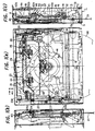
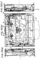
- Figs. 1(a) to 1(c) are views illustrating the structure of the disc reproducing device of the embodiment of the present invention, with Fig. 1(a) showing a plan view, Fig. 1(b) showing a left-hand side view, and Fig. 1(c) showing a right-hand side view.
- the constituent components are depicted without regard to their fore/aft and up/down relationships so that the positional relationships among them are shown in a single paper sheet.
- the areas of these components that have undergone hatching and smudging are not represented as cross sections but as appearances of the components.
- Figs. 1(a) to 1(c) are views illustrating the structure of the disc reproducing device of the embodiment of the present invention, with Fig. 1(a) showing a plan view, Fig. 1(b) showing a left-hand side view, and Fig. 1(c) showing a right-hand side view.
- the constituent components are depicted without regard to their fore/aft
- the entire disc reproducing device is provided with: a chassis mechanism 1 composed of an upper chassis, a lower chassis, and a suspension chassis; a disc conveyance mechanism 11 for conveying a disc between an insertion/ejection position and a reproducing position within the device; a disc detecting mechanism 21 having lock means, the lock means having positioning means used for a small-diameter disc D2 inserted, the lock means for releasing the locking of the positioning means so that it is pushed by the outer periphery of a large-diameter disc D1 to its down position when the inserted disc is a large-diameter disc D1; a suspension lock mechanism 31 for locking and unlocking the suspension chassis in the chassis mechanism 1 in synchronization with the movement of the disc detecting mechanism 21; a disc clamping mechanism 41 disposed in the suspension chassis for clamping the disc conveyed to the reproducing position onto a turntable; and a disc reproducing mechanism for reproducing the disc (not shown).
- the chassis mechanism 1 is composed of the lower chassis 2 and the upper chassis 3 constituting a main chassis, and the suspension chassis 4 supported relatively in the lower chassis 2 via a damper and a damper spring.
- the suspension chassis 4 is locked or unlocked by the suspension lock mechanism 31 with respect to the lower and upper chassises 2 and 3.
- the disc conveyance mechanism 11 has a feed roller 12 which conveys the inserted large disc D1 12 centimeters in diameter or small disc D2 8 centimeters in diameter between the insertion/ejection position and the reproducing position within the device.
- the feed roller 12, a drum-shaped roller whose center portion has a relatively small diameter, is disposed in a feed plate 13 arranged so as to be rockable about a shaft 13a with respect to the lower chassis 2.
- the feed roller 12 has its roller gear 14, formed in the shaft-end portion, engaged with a driving gear 15 disposed in the lower chassis 2, and is thereby rotationally driven.
- the driving gear 15 is rotationally driven by a feed motor (not shown).
- the disc detecting mechanism 21 is provided with a disc detecting lever 22, a lock plate 23, a lock pin 24, an adjusting plate 25, and a shift arm 26.
- the disc detecting lever 22 is rotatably disposed via a shaft 27 in the suspension chassis 4.
- the lock plate 23 moves horizontally in synchronization with the movement of the front end of the disc detecting lever 22.
- the lock pin 24 is, in the normal state, locked by the lock plate 23 in a protruding state so as to position the small-diameter disc D2 inserted into the device in the reproducing position.
- the lock plate 23 is unlocked by the movement of the lock plate 23 in a horizontal, inward direction A, and is pushed to its down position by being pressed by the outer periphery of the inserted large-diameter disc D1. Then, it is locked in its falling-down state by the movement of the lock plate 23 in a horizontal, outward direction B caused by the passage of the largest dimensioned portion of the large-diameter disc D1 over a pin 22a provided in the main end of the disc detecting lever 22.
- the adjusting plate 25 follows the horizontal movement of the lock plate 23 so as to move horizontally, and rotates about a shaft 28.
- the shift arm 26 is arranged so as to be rotatable about the shaft 28 of the adjusting plate 25. Also, the shift arm 26 is unlocked by the movement of the adjusting plate 25 in the horizontal, outward direction B so as to be rotated by being pressed by the outer periphery of the large- or small-diameter disc D1 or D2.
- the disc detecting lever 22 has a pin 22b clamped in its front end so as to extend upwardly.
- the pin 22b is engaged in a slot 23b formed in the front end of the lock plate 23.
- the lock plate 23 is caught in a folded piece 42a formed on the top surface of the clamping arm 42 and arranged so as to be horizontally slidable.
- the lock plate 23 is also loaded by an extension coil spring 23a with a force pushing it in the horizontal, outward direction B.
- the lock pin 24 having a substantially rectangular section is attached to the clamping arm 42 so as to be rotatable about a horizontal shaft 24a.
- the adjusting plate 25 is disposed on the top surface of the clamping arm 42 so as to be rotatable about the shaft 28, and is loaded by an extension coil spring 25a with a force rotating it in a clockwise direction.
- the adjusting plate 25 has its front end 25c abutted against the left end of a rack plate 33, and is thereby positioned.
- the shift arm 26 is disposed on the bottom surface of the clamping arm 42 so as to be rotatable about the shaft 28, and is loaded by an extension coil spring 26a with a force rotating it in a counterclockwise direction.
- the shaft 28 is clamped in the rear end of the shift arm 26 so as to extend upwardly. After passing through a circular hole formed in the clamping arm 42, it is floatably inserted through a slot 25d formed in the adjusting plate 25 and thereafter has its front end caulked. Accordingly, the adjusting plate 25 is movable within the slot 25d.
- the shift arm 26 has a guide pin 26b clamped in its middle portion so as to extend upwardly.
- the guide pin 26b is inserted through a guide hole 42b of the clamping arm 42 so as to be engaged in a guide hole 25e of the adjusting plate 25.
- the guide hole 25e has at both ends inwardly-bent hook-shaped catch portions 25f and 25g.
- an actuating pin 26c At the front end of the shift arm 26 is clamped an actuating pin 26c so as to extend downwardly.
- two positioning projections 42d for positioning the large-diameter disc D1 in the reproducing position are formed inside the clamping arm 42.
- the suspension lock mechanism 31 is provided with: suspension lock plates 32 (hereafter simply referred to as "the sus-lock plate”) disposed at both of left- and right-hand ends of the lower chassis 2 so as to be slidable in forward and backward directions; a lock plate 32a disposed in the lower portion of the sus-lock plate 32 so as to extend inwardly in a horizontal direction and having a Y-shaped lock groove 32b formed therein; a lock plate 4a disposed in the suspension chassis 4 so as to extend downwardly and having a Y-shaped lock groove 4b formed therein; the rack plate 33 disposed in the right-hand sus-lock plate 32 so as to be slidable in forward and backward directions; and an actuating pin 34 clamped in the right-hand sus-lock plate 32 so as to protrude outwardly in a horizontal direction.
- the sus-lock plate 32 and the rack plate 33 are each loaded by an extension coil spring with a force pulling them toward the inside of the device.
- the disc clamping mechanism 41 has clamping arms 42 disposed on both sides of the rear end of the suspension chassis 4 so as to be rockable about a shaft 43.
- the clamping arm 42 has on its top board the above-described disc detecting mechanism 21, and has on the end located in its central portion a circular disc clamp 44 via a clamping spring 45 shaped like a plate spring.
- the disc clamp 44 applies pressure to the disc put in the reproducing position so that the rotation axis of the turntable disposed in the suspension chassis 4 is inserted into the center hole of the disc.
- the right-hand plate 42c has in its front end a guide piece 46 protruding horizontally outwardly so that the clamping arm 42 is engageable with a guide pin 34 of the sus-lock plate 32.
- the disc reproducing mechanism is of conventional type that has a turntable for holding and rotating a disc and a optical pickup for reading a signal from the disc.
- the feed motor rotates and thereby the feed roller 12 conveys the large-diameter disc D1 toward the inside of the device.
- the disc detecting lever 22 is, at the pin 22a provided in its main end, pushed by the outer periphery of the large-diameter disc D1, and is thereby rotated about the shaft 27 in a clockwise direction. Then, through the slot 23b engaged in the pin 22b provided in the front end thereof, the lock plate 23 moves in the horizontal, inward direction A.
- the slot 25d of the adjusting plate 25 is guided by the shaft 28 in movement, and simultaneously the guide pin 26b of the shift arm 26 received in the catch portion 25f of the adjusting plate 25's guide hole 25e moves away from the catch portion 25f. This allows the shift arm 26 to be rotatable about the shaft 28 along the guide hole 25e.
- the lock plate 23 is loaded by the extension coil spring 23a with a force that keeps it pulled in the horizontal, outward direction B.
- the disc detecting lever 22 is rotated in a counterclockwise direction and simultaneously the lock plate 23 moves in the horizontal, outward direction B.
- the lock pin 24 kept in the falling-down state is pushed down from its top side by the outer edge of the lock groove 23c of the lock plate 23 so as to be locked away from the large-diameter disc D1 in the falling-down state.
- the shift lever 26 is, at its front-end pin 26c, pressed by the outer periphery of the large-diameter disc D1 so as to further rotate along with the adjusting plate 25 in a clockwise direction. Simultaneously, the outer periphery of the large-diameter disc D1 abuts against the positioning projection 42d provided in the rear end of the clamping arm 42, thereby achieving positioning. In this state, the center of the large-diameter disc D1 is located inwardly at an offset d relative to the center of the disc clamp, and the adjusting plate 25 is slightly moved toward its original position by the movement of the lock plate 23 in the horizontal, outward direction B. Thus, the shift lever 26 is, at its guide pin 26b, caught in the catch portion 25g provided inside the guide hole 25e of the adjusting plate 25, and is maintained in the state by the extension coil spring 26a.
- the large-diameter disc D1 is held in the device such that its center hole is positioned in the center axis of the turntable. In this way, the center of the large-diameter disc D1 coincides with the center of the turntable, and thus the outer edge of the back portion of the large-diameter disc D1 is located at an offset-equivalent distance from the positioning projection 42d and the front-end pin 26c of the shift arm 26. This state is maintained by the extension coil spring 26a of the adjusting plate 26.
- the turntable in response to the signal fed from the sensor after the detection of this state, the turntable is rotationally driven by the spindle motor, and the optical pickup is activated to read the signal recorded in the large-diameter disc D1, thereby achieving reproduction of the disc.
- the feed roller 12 makes contact with the large-diameter disc D1 so that the large-diameter disc D1 is ejected frontward out of the device.
- the remainder of the operation is the reverse of the above-described operation.
- the large-diameter disc D1 returns to the insertion/ejection position.
- Figs. 7 (a) to 7 (c) in the normal state, the lock plate 23 is maintained in its position by the pull of the extension coil spring 23a.
- the lock piece 24c of the lock pin 24 is pressed down from its top side by the outer edge of the lock groove 23c of the lock plate 23 so that the lock pin 24 protrudes downwardly toward the lower portion of the clamping arm 42.
- the adjusting plate 25 has its rear end 25c pressed by the rack plate 33 and has its front end 25b abutted against the lock plate 23, and is thereby maintained in its position.
- the photodetector detects the insertion and generates a signal.
- the feed motor rotates and thereby the feed roller 12 conveys the small-diameter disc D2 toward the inside of the device.
- the outer periphery of the small-diameter disc D2 pushes the front-end pin 26c of the shift arm 26.
- This causes the shift arm 26 to rotate about the shaft 28 in a clockwise direction.
- the guide pin 26b of the shift arm 26 is received in the catch portion 25f provided in the guide hole 25e of the adjusting plate 25.
- the rotation of the shift arm 26 causes the adjusting plate 25 to rotate. This rotation is stopped by abutting the outer periphery of the small-diameter disc D2 against the lock pin 24, thereby achieving positioning of the small-diameter disc D2.
- the center of the small-diameter disc D2 is located inwardly at an offset d relative to the center of the disc clamp 44.
- the rear end 25c of the adjusting plate 25 pushes the rack plate 33 slightly forward. This causes the rack 33a of the rack plate 33 to mesh with the rotating pinion 16.
- the rack plate 33 is coupled to the sus-lock plate 32 so as to move forward, and the suspension chassis 4 and the lower chassis 3 disengage with each other.
- the clamping arm 42 moves down, and, as shown in Figs. 9(a) to 9(c), the disc clamp 44 holds the small-diameter disc D2 in the turntable.
- the outer edge of the back portion of the small-diameter disc D2 is located at an offset-equivalent distance from the lock pin 24 and the front-end pin 26c of the shift arm 26.
- the turntable rotates and the optical pickup reads the signal recorded in the small-diameter disc D2, thereby achieving reproduction of the disc.
- the disc reproducing device of the embodiment is provided with a disc detecting mechanism 21, the disc detecting mechanism 21 including: a disc detecting lever 22 which is rotated about the shaft 27 by making contact with the outer periphery of the large-diameter disc D1 inserted into the device by the feed roller 12; a lock plate 23 which moves horizontally in synchronization with the movement of the front end of the disc detecting lever 22; a lock pin 24 which is, in the normal state, locked by the lock plate 23 in a protruding state so as to position the small-diameter disc D2 inserted into the device in the reproducing position, is unlocked by the movement of the lock plate 23 in the horizontal, inward direction A, is pushed by the outer periphery of the inserted large-diameter disc D1 to its down position, and is locked in the falling-down state by the movement of the lock plate 23 in the horizontal, outward direction B caused by the passage of the largest dimensioned portion of the large-diameter disc D1
- the lock pin 24 serves to position the small-diameter disc D2 in the reproducing position.
- the lock pin 24 is pushed by the outer periphery of the large-diameter disc D1 to its down position. Accordingly, it is possible to provide an inexpensive and structurally simple disc reproducing device capable of reproducing a disc, regardless of whether it is a large-diameter disc D1 or a small-diameter disc D2, simply by inserting the disc into the device.
Abstract
Description
- The present invention relates to a disc reproducing device capable of reproducing a large-
size disc 12 centimeters in diameter and a small-size disc 8 centimeters in diameter. - Conventionally, a disc reproducing device of this type is designed to drive a large-
size disc 12 centimeters in diameter inserted thereinto. Thus, to reproduce a small-size disc 8 centimeters in diameter, the disc needs to be set in an adapter dedicated thereto before being inserted into the device. - However, such a conventional disc reproducing method of using an adapter has the following disadvantages. An 8-cm - diameter disc cannot be reproduced without an adapter and thus dare needs to be taken for the storage of the adapter. Moreover, mounting an 8- cm-diameter disc in the adapter requires much time.
- According to one aspect of the present invention, there is provided a disc reproducing device having a disc detecting mechanism. The disc detecting mechanism includes: a disc detecting lever; a lock plate; a lock pin; and means for positioning the large-diameter disc. The disc detecting lever has its main end rotated by being pressed by the outer periphery of a large-diameter disc inserted into the device and thereby having its front end moved horizontally. Also, the disc detecting lever rotates in the reverse direction after the passage of the largest dimensioned portion of the large-diameter disc. The lock plate follows the movement of the front end of the disc detecting lever so as to move horizontally. The lock pin is, in the normal state, locked by the lock plate in a protruding state so as to position a small-diameter disc inserted into the device. Also, the lock pin is unlocked by the horizontal movement of the lock plate, and is pushed by the outer periphery of the inserted large-diameter disc to its down position. Furthermore, the lock pin is locked in its falling-down state by the reverse-directional movement of the lock plate caused by the passage of the largest dimensioned portion of the large-diameter disc. In this construction, when a small-diameter disc is inserted into the device, the lock pin positions the small-diameter disc in a reproducing position, and when a large-diameter disc is inserted into the device, the lock pin is pressed by the outer periphery of the large-diameter disc so as to allow the passage of the large-diameter disc. Consequently, either a large-diameter or small-diameter disc can be reproduced.
- Moreover, in the disc reproducing device of the present invention, the aforementioned disc detecting mechanism has an adjusting plate and a shift arm. The adjusting plate follows the horizontal movement of the lock plate so as to move horizontally and moves rotatably about a shaft. The shift arm is arranged rotatably about the shaft, and is unlocked by the horizontal, inward movement of the adjusting plate so that it is rotated by being pressed by the outer periphery of the large-or small-diameter disc. In this construction, regardless of whether a large-diameter disc or a small-diameter disc is inserted, the positioning of the inserted disc in the reproducing position can be detected by confirming the movement of the adjusting plate.
- Further, the disc reproducing device of the present invention has a disc clamping mechanism with clamping means. The disc clamping means rotates in synchronization with the rotation of the adjusting plate and retains a large- or small-diameter disc inserted into the device in a turntable. In this construction, positioning and clamping of a disc can be achieved concurrently.
- Further, the disc reproducing device of the present invention is characterized in that the position of the large-or small-diameter disc determined by the positioning means or the lock pin is offset inwardly in the device relative to the position of the large- or small-diameter disc retained in the turntable by the clamping means. In this construction, when thedisc is retained in the turntable, an offset-equivalent gap is secured between the disc and the positioning means or the lock pin. This makes smooth rotation of the disc possible.
- Further, the disc reproducing device of the present invention has a suspension chassis. The suspension chassis rotationally supports the clamping arm of the disc clamping mechanism and is supported via a damper and a damper spring by the main chassis of the device. In this construction, the suspension chassis, which is in a floating state during reproduction of a disc, is provided with a disc clamping mechanism. This allows the disc reproducing device to be applied to an audio apparatus which receives vibration caused by vehicles or the like.
- Further, in the disc reproducing device of the present invention, the suspension chassis has suspension lock means. The suspension lock means, in the normal state, fixes the suspension chassis to the main chassis, and releases the fixing during reproduction of a disc. In this construction, when a disc is deactivated, the suspension chassis is fixed tightly to the main chassis, and, when the disc is activated, the suspension chassis is kept in a floating state. This enables disc reproduction free of sound fluctuation.
- Further, the disc reproducing device of the present invention is characterized in that, when the adjusting plate rotates, the movement of the adjusting plate drives the suspension lock means to operate, and the movement of the suspension lock means rotates the clamping arm so as to clamp the large- or small-diameter disc. In this construction, the operations ranging from insertion to clamping of a large- or small-diameter disc can be achieved successively in a short period of time.
- According to another aspect of the present invention, a disc reproducing device includes: a chassis mechanism composed of an upper chassis, a lower chassis, and a suspension chassis; a disc conveyance mechanism for conveying a disc between an insertion/ejection position and a reproducing position within the device; a disc detecting mechanism having lock means, the lock means having positioning means used for a small-diameter disc inserted, the lock means for releasing the locking of the positioning means so that it is pushed by the outer periphery of a large-diameter disc to its down position when the inserted disc is the large-diameter disc; a suspension lock mechanism for locking and unlocking the suspension chassis relatively to the lower chassis in synchronization with the movement of the disc detecting mechanism; a disc clamping mechanism disposed in the suspension chassis for clamping the disc conveyed to the reproducing position onto a turntable; and a disc reproducing mechanism for reproducing the clamped disc. In this construction, a disc, regardless of whether it is a large-diameter or small-diameter disc, can be reproduced simply by inserting the disc into the device.
- Accordingly, the disc reproducing device of the present invention is constructed in the following manner. That is, the disc reproducing device having a disc detecting mechanism. The disc detecting mechanism includes: a disc detecting lever; a lock plate; a lock pin; and means for positioning the large-diameter disc. The disc detecting lever has its main end rotated by being pressed by the outer periphery of a large-diameter disc inserted into the device and thereby having its front end moved horizontally. Also, the disc detecting lever rotates in the reverse direction after the passage of the largest dimensioned portion of the large-diameter disc. The lock plate follows the movement of the front end of the disc detecting lever so as to move horizontally. The lock pin is, in the normal state, locked by the lock plate in a protruding state so as to position a small-diameter disc inserted into the device. Also, the lock pin is unlocked by the horizontal movement of the lock plate, and is pushed by the outer periphery of the inserted large-diameter disc to its down position. Furthermore, the lock pin is locked in its falling-down state by the reverse-directional movement of the lock plate caused by the passage of the largest dimensioned portion of the large-diameter disc. With this construction, a disc, regardless of whether it is a large-diameter or small-diameter disc, can be reproduced simply by inserting the disc into the device.
- Moreover, the disc reproducing device of the present invention is constructed in the following manner. That is, the disc reproducing device includes: a chassis mechanism composed of an upper chassis, a lower chassis, and a suspension chassis; a disc conveyance mechanism for conveying a disc between an insertion/ejection position and a reproducing position within the device; a disc detecting mechanism with lock means, the lock means having positioning means used for a small-diameter disc inserted, the lock means for releasing the locking of the positioning means so that it is pushed by the outer periphery of a large-diameter disc to its down position when the inserted disc is the large-diameter disc; a suspension lock mechanism for locking and unlocking the suspension chassis relatively to the lower chassis in synchronization with the movement of the disc detecting mechanism; a disc clamping mechanism disposed in the suspension chassis for clamping the disc conveyed to the reproducing position onto a turntable; and a disc reproducing mechanism for reproducing the clamped disc. With this construction, a disc, regardless of whether it is a large-diameter or small-diameter disc, can be reproduced simply by inserting the disc into the device.
- The present invention has been made to solve the above described problems in the prior art, and has a first object to provide a disc reproducing device capable of reproducing either a large-diameter or small-diameter disc without using an adopter dedicated to a small-diameter disc, and has a second object to provide a disc reproducing device capable of reproducing a disc, regardless of whether it is a large-diameter or small-diameter disc, simply by inserting the disc into the device.
-
- Fig. 1(a) is a schematic plan view illustrating the disc reproducing device of an embodiment of the present invention, wherein a large-diameter disc is inserted thereinto;
- Fig. 1(b) is a schematic left-hand side view illustrating the disc reproducing device of the embodiment of the present invention, wherein a large-diameter disc is inserted thereinto;
- Fig. 1(c) is a schematic right-hand side view illustrating the disc reproducing device of the embodiment of the present invention, wherein a large-diameter disc is inserted thereinto;
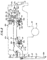
- Fig. 2 is a schematic plan view illustrating the structure of the disc detecting mechanism employed in the embodiment of the present invention;
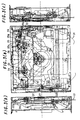
- Fig. 3 (a) is a schematic plan view illustrating the disc reproducing device of the embodiment of the present invention into which a large-diameter disc is inserted, with its lock pin being left in a released state;
- Fig. 3 (b) is a schematic left-hand side view illustrating the disc reproducing device of the embodiment of the present invention into which a large-diameter disc is inserted, with its lock pin being left in a released state;
- Fig. 3(c) is a schematic right-hand side view illustrating the disc reproducing device of the embodiment of the present invention into which a large-diameter disc is inserted, with its lock pin being left in a released state;
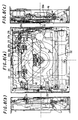
- Fig. 4(a) is a schematic plan view illustrating the disc reproducing device of the embodiment of the present invention into which a large-diameter disc is inserted, with the disc being positioned;
- Fig. 4(b) is a schematic left-hand side view illustrating the disc reproducing device of the embodiment of the present invention into which a large-diameter disc is inserted, with the disc being positioned;
- Fig. 4(c) is a schematic right-hand side view illustrating the disc reproducing device of the embodiment of the present invention into which a large-diameter disc is inserted, with the disc being positioned;
- Fig. 5(a) is a schematic plan view illustrating the disc reproducing device of the embodiment of the present invention into which a large-diameter disc is inserted, with the disc being clamped;
- Fig. 5 (b) is a schematic left-hand side view illustrating the disc reproducing device of the embodiment of the present invention into which a large-diameter disc is inserted, with the disc being clamped;
- Fig. 5(c) is a schematic right-hand side view illustrating the disc reproducing device of the embodiment of the present invention into which a large-diameter disc is inserted, with the disc being clamped;
- Fig. 6(a) is a schematic plan view illustrating the disc reproducing device of the embodiment of the present invention, wherein a large-diameter disc is being ejected therefrom;
- Fig. 6(b) is a schematic left-hand side view illustrating the disc reproducing device of the embodiment of the present invention, wherein a large-diameter disc is being ejected therefrom;
- Fig. 6(c) is a schematic right-hand side view illustrating the disc reproducing device of the embodiment of the present invention, wherein a large-diameter disc is being ejected therefrom;
- Fig. 7(a) is a schematic plan view illustrating the disc reproducing device of the embodiment of the present invention, wherein a small-diameter disc is inserted thereinto;
- Fig. 7 (b) is a schematic left-hand side view illustrating the disc reproducing device of the embodiment of the present invention, wherein a small-diameter disc is inserted thereinto;
- Fig. 7(c) is a schematic right-hand side view illustrating the disc reproducing device of the embodiment of the present invention, wherein a small-diameter disc is inserted thereinto;
- Fig. 8 (a) is a schematic plan view illustrating the disc reproducing device of the embodiment of the present invention into which a small-diameter disc is inserted, with the disc being positioned;
- Fig. 8(b) is a'schematic left-hand side view illustrating the disc reproducing device of the embodiment of the present invention into which a small-diameter disc is inserted, with the disc being positioned;
- Fig. 8(c) is a schematic right-hand side view illustrating the disc reproducing device of the embodiment of the present invention into which a small-diameter disc is inserted, with the disc being positioned;
- Fig. 9(a) is a schematic plan view illustrating the disc reproducing device of the embodiment of the present invention into which a small-diameter disc is inserted, with the disc being clamped;
- Fig. 9 (b) is a schematic left-hand side view illustrating the disc reproducing device of the embodiment of the present invention into which a small-diameter disc is inserted, with the disc being clamped;
- Fig. 9(c) is a schematic right-hand side view illustrating the disc reproducing device of the embodiment of the present invention into which a small-diameter disc is inserted, with the disc being clamped;
- Fig. 10(a) is a schematic plan view illustrating the disc reproducing device of the embodiment of the present invention, wherein a small-diameter disc is being ejected therefrom;
- Fig. 10(b) is a schematic left-hand side view illustrating the disc reproducing device of the embodiment of the present invention, wherein a small-diameter disc is being ejected therefrom; and
- Fig. 10(c) is a schematic right-hand side view illustrating the disc reproducing device of the embodiment of the present invention, wherein a small-diameter disc is being ejected therefrom.
-
- The above and further objects and features of the present invention will more fully be apparent from the following detailed description taken in conjunction with the accompanying drawings.
- Hereinafter, an embodiment of the present invention will be described with reference to the drawings. Note that the novel feature believed characteristic of the present invention is that a disc, regardless of whether it is a large-diameter or small-diameter disc, can be reproduced simply by inserting the disc into the device. Thus, only a brief description will be given as to the other structural aspects thereof.
- Figs. 1(a) to 1(c) are views illustrating the structure of the disc reproducing device of the embodiment of the present invention, with Fig. 1(a) showing a plan view, Fig. 1(b) showing a left-hand side view, and Fig. 1(c) showing a right-hand side view. In these figures, the constituent components are depicted without regard to their fore/aft and up/down relationships so that the positional relationships among them are shown in a single paper sheet. Moreover, the areas of these components that have undergone hatching and smudging are not represented as cross sections but as appearances of the components. In Figs. 1(a) to 1(c), the entire disc reproducing device is provided with: a chassis mechanism 1 composed of an upper chassis, a lower chassis, and a suspension chassis; a disc conveyance mechanism 11 for conveying a disc between an insertion/ejection position and a reproducing position within the device; a
disc detecting mechanism 21 having lock means, the lock means having positioning means used for a small-diameter disc D2 inserted, the lock means for releasing the locking of the positioning means so that it is pushed by the outer periphery of a large-diameter disc D1 to its down position when the inserted disc is a large-diameter disc D1; asuspension lock mechanism 31 for locking and unlocking the suspension chassis in the chassis mechanism 1 in synchronization with the movement of thedisc detecting mechanism 21; adisc clamping mechanism 41 disposed in the suspension chassis for clamping the disc conveyed to the reproducing position onto a turntable; and a disc reproducing mechanism for reproducing the disc (not shown). - The chassis mechanism 1 is composed of the
lower chassis 2 and theupper chassis 3 constituting a main chassis, and thesuspension chassis 4 supported relatively in thelower chassis 2 via a damper and a damper spring. Thesuspension chassis 4 is locked or unlocked by thesuspension lock mechanism 31 with respect to the lower and upper chassises 2 and 3. - The disc conveyance mechanism 11 has a
feed roller 12 which conveys the insertedlarge disc D1 12 centimeters in diameter or small disc D2 8 centimeters in diameter between the insertion/ejection position and the reproducing position within the device. Thefeed roller 12, a drum-shaped roller whose center portion has a relatively small diameter, is disposed in afeed plate 13 arranged so as to be rockable about ashaft 13a with respect to thelower chassis 2. Thefeed roller 12 has itsroller gear 14, formed in the shaft-end portion, engaged with adriving gear 15 disposed in thelower chassis 2, and is thereby rotationally driven. Thedriving gear 15 is rotationally driven by a feed motor (not shown). - The
disc detecting mechanism 21 is provided with adisc detecting lever 22, alock plate 23, alock pin 24, an adjustingplate 25, and ashift arm 26. Thedisc detecting lever 22 is rotatably disposed via ashaft 27 in thesuspension chassis 4. Thelock plate 23 moves horizontally in synchronization with the movement of the front end of thedisc detecting lever 22. Thelock pin 24 is, in the normal state, locked by thelock plate 23 in a protruding state so as to position the small-diameter disc D2 inserted into the device in the reproducing position. Also, it is unlocked by the movement of thelock plate 23 in a horizontal, inward direction A, and is pushed to its down position by being pressed by the outer periphery of the inserted large-diameter disc D1. Then, it is locked in its falling-down state by the movement of thelock plate 23 in a horizontal, outward direction B caused by the passage of the largest dimensioned portion of the large-diameter disc D1 over apin 22a provided in the main end of thedisc detecting lever 22. The adjustingplate 25 follows the horizontal movement of thelock plate 23 so as to move horizontally, and rotates about ashaft 28. Theshift arm 26 is arranged so as to be rotatable about theshaft 28 of the adjustingplate 25. Also, theshift arm 26 is unlocked by the movement of the adjustingplate 25 in the horizontal, outward direction B so as to be rotated by being pressed by the outer periphery of the large- or small-diameter disc D1 or D2. - As shown in Fig. 2, the
disc detecting lever 22 has apin 22b clamped in its front end so as to extend upwardly. Thepin 22b is engaged in aslot 23b formed in the front end of thelock plate 23. Thelock plate 23 is caught in a foldedpiece 42a formed on the top surface of the clampingarm 42 and arranged so as to be horizontally slidable. Thelock plate 23 is also loaded by an extension coil spring 23a with a force pushing it in the horizontal, outward direction B. Thelock pin 24 having a substantially rectangular section is attached to the clampingarm 42 so as to be rotatable about ahorizontal shaft 24a. Also, it is loaded by atorsion coil spring 24b with a force rotating it about thehorizontal shaft 24a in a counterclockwise direction as seen from the left-hand side. Furthermore, thelock pin 24 is caught, in the normal state, in arectangular lock groove 23c formed in thelock plate 23 so as to protrude downwardly, and is locked in the protruding state by having its inwardly-protrudinglock piece 24c pressed by the outer edge of thelock groove 23c of thelock plate 23. The adjustingplate 25 is disposed on the top surface of the clampingarm 42 so as to be rotatable about theshaft 28, and is loaded by an extension coil spring 25a with a force rotating it in a clockwise direction. The adjustingplate 25 has itsfront end 25c abutted against the left end of arack plate 33, and is thereby positioned. Theshift arm 26 is disposed on the bottom surface of the clampingarm 42 so as to be rotatable about theshaft 28, and is loaded by anextension coil spring 26a with a force rotating it in a counterclockwise direction. Theshaft 28 is clamped in the rear end of theshift arm 26 so as to extend upwardly. After passing through a circular hole formed in the clampingarm 42, it is floatably inserted through aslot 25d formed in the adjustingplate 25 and thereafter has its front end caulked. Accordingly, the adjustingplate 25 is movable within theslot 25d. Moreover, theshift arm 26 has aguide pin 26b clamped in its middle portion so as to extend upwardly. Theguide pin 26b is inserted through aguide hole 42b of the clampingarm 42 so as to be engaged in aguide hole 25e of the adjustingplate 25. Theguide hole 25e has at both ends inwardly-bent hook-shapedcatch portions shift arm 26 is clamped anactuating pin 26c so as to extend downwardly. Moreover, inside the clampingarm 42 twopositioning projections 42d for positioning the large-diameter disc D1 in the reproducing position are formed. - In Figs. 1(a) to 1(c), the
suspension lock mechanism 31 is provided with: suspension lock plates 32 (hereafter simply referred to as "the sus-lock plate") disposed at both of left- and right-hand ends of thelower chassis 2 so as to be slidable in forward and backward directions; alock plate 32a disposed in the lower portion of the sus-lock plate 32 so as to extend inwardly in a horizontal direction and having a Y-shapedlock groove 32b formed therein; alock plate 4a disposed in thesuspension chassis 4 so as to extend downwardly and having a Y-shapedlock groove 4b formed therein; therack plate 33 disposed in the right-hand sus-lock plate 32 so as to be slidable in forward and backward directions; and anactuating pin 34 clamped in the right-hand sus-lock plate 32 so as to protrude outwardly in a horizontal direction. The sus-lock plate 32 and therack plate 33 are each loaded by an extension coil spring with a force pulling them toward the inside of the device. - The
disc clamping mechanism 41 has clampingarms 42 disposed on both sides of the rear end of thesuspension chassis 4 so as to be rockable about ashaft 43. The clampingarm 42 has on its top board the above-describeddisc detecting mechanism 21, and has on the end located in its central portion acircular disc clamp 44 via aclamping spring 45 shaped like a plate spring. Thedisc clamp 44 applies pressure to the disc put in the reproducing position so that the rotation axis of the turntable disposed in thesuspension chassis 4 is inserted into the center hole of the disc. Moreover, of the plates provided on both sides of the clampingarm 42, the right-hand plate 42c has in its front end aguide piece 46 protruding horizontally outwardly so that the clampingarm 42 is engageable with aguide pin 34 of the sus-lock plate 32. The disc reproducing mechanism is of conventional type that has a turntable for holding and rotating a disc and a optical pickup for reading a signal from the disc. - Next, a description will be given below as to the operation of the disc reproducing device of the embodiment, as observed when a
large disc 12 centimeters in diameter is inserted thereinto. In Figs. 1(a) to 1(c) and Fig. 2, in the normal state, thelock plate 23 of thedisc detecting mechanism 21 is maintained in its position by the pull of the extension coil spring 23a. Thelock piece 24c of thelock pin 24 is pushed down from its top side by the outer edge of thelock groove 23c of thelock plate 23 so that thelock pin 24 protrudes downwardly toward the lower portion of the clampingarm 42. Moreover, the adjustingplate 25 has itsrear end 25c pushed by the rack plate 33 (stopped at a prescribed position), and is thereby maintained in its position. In this state, when thelarge disc D1 12 centimeter in diameter is inserted into the device, photodetector detects the insertion and generates a signal. In response to this signal, the feed motor rotates and thereby thefeed roller 12 conveys the large-diameter disc D1 toward the inside of the device. After the conveyance of the large-diameter disc D1, thedisc detecting lever 22 is, at thepin 22a provided in its main end, pushed by the outer periphery of the large-diameter disc D1, and is thereby rotated about theshaft 27 in a clockwise direction. Then, through theslot 23b engaged in thepin 22b provided in the front end thereof, thelock plate 23 moves in the horizontal, inward direction A. - In this way, as shown in Figs. 3(a) to (c), the
lock groove 23c of thelock plate 23 moves away from thelock pin 24. This allows thelock pin 24 to be rotatable about thehorizontal shaft 24a. Then, the downwardly protrudinglock pin 24 is pushed by the outer periphery of the large-diameter disc D1 against thetorsion spring 24b, and is thereby rotated so as to be brought to its down position. Consequently, the large-diameter disc D1 is further directed toward the inside of the device over thelock pin 24. Moreover, as shown in Fig. 2, as thelock plate 23 moves in the horizontal, inward direction A, its right-hand end pushes the adjustingplate 25 in the same direction. Thus, theslot 25d of the adjustingplate 25 is guided by theshaft 28 in movement, and simultaneously theguide pin 26b of theshift arm 26 received in thecatch portion 25f of the adjustingplate 25'sguide hole 25e moves away from thecatch portion 25f. This allows theshift arm 26 to be rotatable about theshaft 28 along theguide hole 25e. - Then, after the passage of the largest dimensioned portion of the large-diameter disc D1 over the
pin 22a provided in the main end of thedisc detecting lever 22, thelock plate 23 is loaded by the extension coil spring 23a with a force that keeps it pulled in the horizontal, outward direction B. Thus, as shown in Figs. 4(a) to 4(c), thedisc detecting lever 22 is rotated in a counterclockwise direction and simultaneously thelock plate 23 moves in the horizontal, outward direction B. Then, thelock pin 24 kept in the falling-down state is pushed down from its top side by the outer edge of thelock groove 23c of thelock plate 23 so as to be locked away from the large-diameter disc D1 in the falling-down state. Moreover, theshift lever 26 is, at its front-end pin 26c, pressed by the outer periphery of the large-diameter disc D1 so as to further rotate along with the adjustingplate 25 in a clockwise direction. Simultaneously, the outer periphery of the large-diameter disc D1 abuts against thepositioning projection 42d provided in the rear end of the clampingarm 42, thereby achieving positioning. In this state, the center of the large-diameter disc D1 is located inwardly at an offset d relative to the center of the disc clamp, and the adjustingplate 25 is slightly moved toward its original position by the movement of thelock plate 23 in the horizontal, outward direction B. Thus, theshift lever 26 is, at itsguide pin 26b, caught in thecatch portion 25g provided inside theguide hole 25e of the adjustingplate 25, and is maintained in the state by theextension coil spring 26a. - In Figs. 4(a) to 4(c), as the adjusting
plate 25 rotates about theshaft 28 in a clockwise direction, itsrear end 25c pushes therack plate 33 forward. Then, arack 33a of therack plate 33 meshes with apinion 16 which is rotationally disposed in thelower chassis 3 and is rotationally driven by the feed motor. By the action of thepinion 16, therack plate 33 is locked by the sus-lock plate 32 in a position slightly forward of its original position. In this way, as shown in Figs. 5(a) to 5(c), the sus-lock plate 32 is conveyed by thepinion 16 to the forward predetermined position. This causes the Y-shapedlock groove 32b of the sus-lock plate 32 to be disengaged from the Y-shapedlock groove 4b of thesuspension chassis 4, and thus thesuspension chassis 4 is supported by the damper in the floating state. Simultaneously, thefeed plate 13 is rotated by the front end of the sus-lock plate 32 about theshaft 13a in a clockwise direction, and thefeed roller 12 moves away from the large-diameter disc D1 and is locked in the state. Moreover, theguide pin 34 of the sus-lock plate 32 is detached from theguide piece 46 formed in the right-hand plate 42c of the clampingarm 42. This causes the clampingarm 42 to rotate downwardly about theshaft 43, and itsdisc clamp 44 pushes the large-diameter disc D1. Consequently, the large-diameter disc D1 is held in the device such that its center hole is positioned in the center axis of the turntable. In this way, the center of the large-diameter disc D1 coincides with the center of the turntable, and thus the outer edge of the back portion of the large-diameter disc D1 is located at an offset-equivalent distance from thepositioning projection 42d and the front-end pin 26c of theshift arm 26. This state is maintained by theextension coil spring 26a of the adjustingplate 26. Moreover, in response to the signal fed from the sensor after the detection of this state, the turntable is rotationally driven by the spindle motor, and the optical pickup is activated to read the signal recorded in the large-diameter disc D1, thereby achieving reproduction of the disc. - Now, an ejecting operation for ejecting the large-diameter disc D1 out of the device will be described below. On completion of reproduction of the large-diameter disc D1, the ejection button is pressed and the feed motor is rotated in the reverse direction. Consequently, in Figs. 5(a) to 5(c), the
pinion 16 acts to move therack plate 33 and the sus-lock plate 32 inward. This, as shown in Figs. 4(a) to 4(c), causes thefeed plate 13 to be unlocked and return to its original position by the force exerted by the spring. Subsequently, thefeed roller 12 makes contact with the large-diameter disc D1 so that the large-diameter disc D1 is ejected frontward out of the device. The remainder of the operation is the reverse of the above-described operation. On completion of the operation, as shown in Figs. 6(a) to 6(c), the large-diameter disc D1 returns to the insertion/ejection position. - Secondly, a description will be given below as to the operation of the disc reproducing device, as observed when a small disc 8 centimeters in diameter is inserted thereinto. In Figs. 7 (a) to 7 (c), in the normal state, the
lock plate 23 is maintained in its position by the pull of the extension coil spring 23a. Thelock piece 24c of thelock pin 24 is pressed down from its top side by the outer edge of thelock groove 23c of thelock plate 23 so that thelock pin 24 protrudes downwardly toward the lower portion of the clampingarm 42. Moreover, the adjustingplate 25 has itsrear end 25c pressed by therack plate 33 and has its front end 25b abutted against thelock plate 23, and is thereby maintained in its position. In this state, when the small-diameter disc D2 is inserted into the device, the photodetector detects the insertion and generates a signal. In response to this signal, the feed motor rotates and thereby thefeed roller 12 conveys the small-diameter disc D2 toward the inside of the device. - After the small-diameter disc D2 is conveyed inside the device, as shown in Figs. 8(a) to 8(C), the outer periphery of the small-diameter disc D2 pushes the front-
end pin 26c of theshift arm 26. This causes theshift arm 26 to rotate about theshaft 28 in a clockwise direction. Theguide pin 26b of theshift arm 26 is received in thecatch portion 25f provided in theguide hole 25e of the adjustingplate 25. Thus, the rotation of theshift arm 26 causes the adjustingplate 25 to rotate. This rotation is stopped by abutting the outer periphery of the small-diameter disc D2 against thelock pin 24, thereby achieving positioning of the small-diameter disc D2. In this state, the center of the small-diameter disc D2 is located inwardly at an offset d relative to the center of thedisc clamp 44. Then, therear end 25c of the adjustingplate 25 pushes therack plate 33 slightly forward. This causes therack 33a of therack plate 33 to mesh with therotating pinion 16. Then, in a manner similar to that described above, therack plate 33 is coupled to the sus-lock plate 32 so as to move forward, and thesuspension chassis 4 and thelower chassis 3 disengage with each other. Subsequently, the clampingarm 42 moves down, and, as shown in Figs. 9(a) to 9(c), thedisc clamp 44 holds the small-diameter disc D2 in the turntable. In this state, the outer edge of the back portion of the small-diameter disc D2 is located at an offset-equivalent distance from thelock pin 24 and the front-end pin 26c of theshift arm 26. In response to the signal fed from the sensor, the turntable rotates and the optical pickup reads the signal recorded in the small-diameter disc D2, thereby achieving reproduction of the disc. - On completion of reproduction of the small-diameter disc D2, the ejection button is pressed and the feed motor is rotated in the reverse direction. Thus, in Figs. 9(a) to 9(c), the
pinion 16 acts to move therack plate 33 and the sus-lock plate 32 inward. This, as shown in Figs. 8(a) to 8(c), causes thefeed plate 13 to be unlocked and return to its original position by the force exerted by the spring. Then, thefeed roller 12 makes contact with the small-diameter disc D2 so that the small-diameter disc D2 is ejected frontward out of the device. The remainder of the operation is the reverse of the above-described operation. On completion of the operation, as shown in Figs. 10 (a) to 10 (c), the small-diameter disc D2 returns to the insertion/ejection position. - As described heretofore, the disc reproducing device of the embodiment is provided with a disc detecting mechanism 21, the disc detecting mechanism 21 including: a disc detecting lever 22 which is rotated about the shaft 27 by making contact with the outer periphery of the large-diameter disc D1 inserted into the device by the feed roller 12; a lock plate 23 which moves horizontally in synchronization with the movement of the front end of the disc detecting lever 22; a lock pin 24 which is, in the normal state, locked by the lock plate 23 in a protruding state so as to position the small-diameter disc D2 inserted into the device in the reproducing position, is unlocked by the movement of the lock plate 23 in the horizontal, inward direction A, is pushed by the outer periphery of the inserted large-diameter disc D1 to its down position, and is locked in the falling-down state by the movement of the lock plate 23 in the horizontal, outward direction B caused by the passage of the largest dimensioned portion of the large-diameter disc D1 over the pin 22a provided in the main end of the disc detecting lever 22; an adjusting plate 25 which follows the horizontal movement of the lock plate 23 so as to move in the same direction, and is rotatable about the shaft 28; and a shift arm 26 which is so arranged as to be rotatable about the shaft 28, is unlocked by the horizontal movement of the adjusting plate 25, and is rotated by being pressed by the outer periphery of the large- or small-diameter disc D1 or D2. In this construction, when the small-diameter disc D2 is inserted into the device, the
lock pin 24 serves to position the small-diameter disc D2 in the reproducing position. On the other hand, when the large-diameter disc D1 is inserted into the device, thelock pin 24 is pushed by the outer periphery of the large-diameter disc D1 to its down position. Accordingly, it is possible to provide an inexpensive and structurally simple disc reproducing device capable of reproducing a disc, regardless of whether it is a large-diameter disc D1 or a small-diameter disc D2, simply by inserting the disc into the device. - Although the present invention has been particularly shown and described with reference to a preferred embodiment illustrated in the accompanying drawings, it will be apparent to those skilled in the art that various changes and modifications can be made without departing from the spirit of the present invention. Accordingly, it is intended to encompass within the appended claims all such changes and modifications that fall within the scope of the present invention.
Claims (8)
- A disc reproducing device having a disc detecting mechanism, the disc detecting mechanism comprising:a disc detecting lever having its main end rotated by being pressed by an outer periphery of a large-diameter disc inserted into the device and thereby having its front end moved horizontally, the disc detecting lever rotating in a reverse direction after passage of a largest dimensioned portion of said large-diameter disc;a lock plate which follows an movement of the front end of said disc detecting lever so as to move horizontally;a lock pin which is, in a normal state, locked by said lock plate in a protruding state so as to position a small-diameter disc inserted into the device, is unlocked by the horizontal movement of said lock plate, is pushed by the outer periphery of said inserted large-diameter disc to its down position, and is locked in its falling-down state by a reverse-direction movement of said lock plate caused by the passage of the largest dimensioned portion of said large-diameter disc; andmeans for positioning said large-diameter disc.
- The disc reproducing device according to claim 1, wherein said disc detecting mechanism further comprising:an adjusting plate which follows the horizontal movement of said lock plate so as to move horizontally, and moves rotatably about a shaft; anda shift arm arranged rotatably about said shaft, the shift arm being unlocked by a horizontal, inward movement of said adjusting plate and rotated by being pressed by the outer periphery of said large- or small-diameter disc.
- The disc reproducing device according to claim 2, further comprising:
a disc clamping mechanism having clamping means, the clamping means rotating in synchronization with a rotation of said adjusting plate and retaining said large- or small-diameter disc inserted into the device in a turntable. - The disc reproducing device according to claim 3,
wherein a position of said large- or small-diameter disc determined by said positioning means or said lock pin is offset inwardly in the device relative to a position of said large- or small-diameter disc retained in the turntable by said clamping means. - The disc reproducing device according to claim 4, further comprising:
a suspension chassis for rotationally supporting a clamping arm of said disc clamping mechanism, the suspension chassis being supported via a damper and a damper spring by a main chassis of the device. - The disc reproducing device according to claim 5,
wherein said suspension chassis has suspension lock means for fixing, in a normal state, said suspension chassis to said main chassis and for releasing the fixing during reproduction of a disc. - The disc reproducing device according to claim 6,
wherein, when said adjusting plate rotates, a movement of said adjusting plate drives said suspension lock means to operate, and a movement of said suspension lock means rotates said clamping arm so as to clamp said large- or small-diameter disc. - A disc reproducing device comprising:a chassis mechanism composed of an upper chassis, a lower chassis, and a suspension chassis;a disc conveyance mechanism for conveying a disc between an insertion/ejection position and a reproducing position within the device;a disc detecting mechanism having lock means, the lock means having positioning means used for a small-diameter disc inserted, the lock means for releasing the locking of said positioning means so that it is pushed by the outer periphery of a large-diameter disc to its down position when the inserted disc is the large-diameter disc;a suspension lock mechanism for locking and unlocking said suspension chassis relatively to said lower chassis in synchronization with the movement of said disc detecting mechanism;a disc clamping mechanism disposed in said suspension chassis for clamping the disc conveyed to said reproducing position onto a turntable; anda disc reproducing mechanism for reproducing said clamped disc.
Applications Claiming Priority (2)
| Application Number | Priority Date | Filing Date | Title |
|---|---|---|---|
| JP2000165088A JP3801842B2 (en) | 2000-06-01 | 2000-06-01 | Disc player |
| JP2000165088 | 2000-06-01 |
Publications (2)
| Publication Number | Publication Date |
|---|---|
| EP1160784A2 true EP1160784A2 (en) | 2001-12-05 |
| EP1160784A3 EP1160784A3 (en) | 2002-11-27 |
Family
ID=18668615
Family Applications (1)
| Application Number | Title | Priority Date | Filing Date |
|---|---|---|---|
| EP01113314A Withdrawn EP1160784A3 (en) | 2000-06-01 | 2001-05-31 | Disc reproducing device |
Country Status (4)
| Country | Link |
|---|---|
| US (1) | US6661764B2 (en) |
| EP (1) | EP1160784A3 (en) |
| JP (1) | JP3801842B2 (en) |
| CN (1) | CN1218312C (en) |
Cited By (1)
| Publication number | Priority date | Publication date | Assignee | Title |
|---|---|---|---|---|
| EP1396861A2 (en) * | 2002-09-03 | 2004-03-10 | Matsushita Electric Industrial Co., Ltd. | Optical disk driving apparatus |
Families Citing this family (10)
| Publication number | Priority date | Publication date | Assignee | Title |
|---|---|---|---|---|
| KR100427358B1 (en) * | 2002-02-25 | 2004-04-13 | 삼성전기주식회사 | Disk guide device of compact disk player for vehicle |
| KR100427360B1 (en) * | 2002-02-25 | 2004-04-13 | 삼성전기주식회사 | Clamp driving device of compact disk player for vehicle |
| KR100437111B1 (en) * | 2002-06-22 | 2004-06-23 | 삼성전자주식회사 | Optical disk roading apparatus for optical disk drive |
| JP4096817B2 (en) * | 2003-06-06 | 2008-06-04 | 日本ビクター株式会社 | Disk drive device |
| JP4316423B2 (en) * | 2004-05-19 | 2009-08-19 | パナソニック株式会社 | Disc transport device and optical disc recording / reproducing device |
| CN101142627B (en) * | 2005-04-12 | 2010-05-19 | 松下电器产业株式会社 | Disk device |
| JP3839833B1 (en) | 2005-04-25 | 2006-11-01 | タナシン電機株式会社 | Disk centering device. |
| CN101727936B (en) * | 2008-10-15 | 2011-05-04 | 谷林电器(深圳)有限公司 | Position detection device of optical disc loading terminal |
| US8887183B2 (en) * | 2011-11-18 | 2014-11-11 | Panasonic Corporation | Optical disc device and lens cleaner |
| CN110823049A (en) * | 2019-11-26 | 2020-02-21 | 奇瑞汽车股份有限公司 | Rear suspension lower body checking fixture and detection method thereof |
Citations (3)
| Publication number | Priority date | Publication date | Assignee | Title |
|---|---|---|---|---|
| GB2120831A (en) * | 1982-04-23 | 1983-12-07 | Staar Sa | Automatic disc loading apparatus |
| EP0296829A2 (en) * | 1987-06-23 | 1988-12-28 | Sony Corporation | Disc drive arrangement for CD player and the like capable of loading different size discs |
| US5031169A (en) * | 1988-04-30 | 1991-07-09 | Alpine Electronics Inc. | Recording disc player for discs of different diameter |
Family Cites Families (16)
| Publication number | Priority date | Publication date | Assignee | Title |
|---|---|---|---|---|
| JPS5788561A (en) * | 1980-11-19 | 1982-06-02 | Pioneer Electronic Corp | Automatic loading record player |
| BE893023A (en) * | 1982-04-29 | 1982-08-16 | Staar Sa | RECORDER WITH AUTOMATIC DISC LOADING. |
| DE4004562B4 (en) * | 1989-02-16 | 2008-05-08 | Pioneer Electronic Corp. | In-vehicle turntable |
| US5226028A (en) * | 1989-02-16 | 1993-07-06 | Pioneer Electronic Corporation | Centering mechanism for automotive disk player |
| US5173893A (en) * | 1989-03-03 | 1992-12-22 | Pioneer Electronic Corporation | Disc double insertion preventing mechanism for disc player |
| GB2230893B (en) * | 1989-03-13 | 1993-09-01 | Pioneer Electronic Corp | Guide mechanism for disc reproducing apparatus |
| US5031171A (en) * | 1989-03-27 | 1991-07-09 | Pioneer Electronic Corporation | Centering mechanism for automotive disc player |
| JPH0679405B2 (en) * | 1989-08-11 | 1994-10-05 | パイオニア株式会社 | Disc player |
| US5590109A (en) * | 1993-09-17 | 1996-12-31 | Matsushita Electric Industrial Co. | Disc apparatus |
| JPH08315478A (en) * | 1995-05-13 | 1996-11-29 | Nakamichi Corp | Disk transfer device |
| JPH1092080A (en) | 1996-09-13 | 1998-04-10 | Tokyo Pijiyon Kk | Disk device |
| EP0836184B1 (en) * | 1996-10-10 | 2004-12-29 | Lg Electronics Inc. | A disc loading and unloading apparatus of an optical disc player |
| US6445665B2 (en) * | 1997-01-20 | 2002-09-03 | Sony Corporation | Disc centering mechanism in disc playback and/or recording apparatus |
| JPH1186401A (en) * | 1997-09-04 | 1999-03-30 | Tanashin Denki Co | Disk loading device for disk reproducing device |
| KR100277960B1 (en) * | 1997-12-04 | 2001-01-15 | 윤종용 | Optical disc loading device |
| US6469971B1 (en) * | 1998-12-28 | 2002-10-22 | Pioneer Corporation | Device for reproducing optical discs |
-
2000
- 2000-06-01 JP JP2000165088A patent/JP3801842B2/en not_active Expired - Fee Related
-
2001
- 2001-05-31 EP EP01113314A patent/EP1160784A3/en not_active Withdrawn
- 2001-06-01 CN CN011221712A patent/CN1218312C/en not_active Expired - Fee Related
- 2001-06-01 US US09/870,997 patent/US6661764B2/en not_active Expired - Fee Related
Patent Citations (3)
| Publication number | Priority date | Publication date | Assignee | Title |
|---|---|---|---|---|
| GB2120831A (en) * | 1982-04-23 | 1983-12-07 | Staar Sa | Automatic disc loading apparatus |
| EP0296829A2 (en) * | 1987-06-23 | 1988-12-28 | Sony Corporation | Disc drive arrangement for CD player and the like capable of loading different size discs |
| US5031169A (en) * | 1988-04-30 | 1991-07-09 | Alpine Electronics Inc. | Recording disc player for discs of different diameter |
Cited By (2)
| Publication number | Priority date | Publication date | Assignee | Title |
|---|---|---|---|---|
| EP1396861A2 (en) * | 2002-09-03 | 2004-03-10 | Matsushita Electric Industrial Co., Ltd. | Optical disk driving apparatus |
| EP1396861A3 (en) * | 2002-09-03 | 2006-08-02 | Matsushita Electric Industrial Co., Ltd. | Optical disk driving apparatus |
Also Published As
| Publication number | Publication date |
|---|---|
| EP1160784A3 (en) | 2002-11-27 |
| CN1218312C (en) | 2005-09-07 |
| CN1337694A (en) | 2002-02-27 |
| JP3801842B2 (en) | 2006-07-26 |
| US6661764B2 (en) | 2003-12-09 |
| US20020018427A1 (en) | 2002-02-14 |
| JP2001344861A (en) | 2001-12-14 |
Similar Documents
| Publication | Publication Date | Title |
|---|---|---|
| US6661764B2 (en) | Disc reproducing device | |
| US6445665B2 (en) | Disc centering mechanism in disc playback and/or recording apparatus | |
| GB2098784A (en) | Rotary recording medium reproducing apparatus | |
| EP1100083B1 (en) | Disk player | |
| JPH07220353A (en) | Disk loading device | |
| JP3949856B2 (en) | Recording medium playback device | |
| JP3749124B2 (en) | Disk unit | |
| JPH0138767Y2 (en) | ||
| JP3949855B2 (en) | Recording medium playback device | |
| JP2900665B2 (en) | Disc loading device | |
| JP3714352B2 (en) | Disc loading device | |
| JP4141657B2 (en) | Disc player | |
| JPH0138772Y2 (en) | ||
| JP2005332550A (en) | Optical disk player of slot in type | |
| JP3739578B2 (en) | Recording medium driving device | |
| JPH0138771Y2 (en) | ||
| JPH0115016Y2 (en) | ||
| JP3329138B2 (en) | Magneto-optical disk recording / reproducing device | |
| JPH0138768Y2 (en) | ||
| JP3511487B2 (en) | Disk drive device | |
| JPH0222844Y2 (en) | ||
| JPH05128695A (en) | Disk loading device | |
| JP3591019B2 (en) | Disc loading mechanism | |
| JP3694417B2 (en) | Recording medium driving device | |
| JP3815560B2 (en) | Disk unit |
Legal Events
| Date | Code | Title | Description |
|---|---|---|---|
| PUAI | Public reference made under article 153(3) epc to a published international application that has entered the european phase |
Free format text: ORIGINAL CODE: 0009012 |
|
| AK | Designated contracting states |
Kind code of ref document: A2 Designated state(s): AT BE CH CY DE DK ES FI FR GB GR IE IT LI LU MC NL PT SE TR |
|
| AX | Request for extension of the european patent |
Free format text: AL;LT;LV;MK;RO;SI |
|
| PUAL | Search report despatched |
Free format text: ORIGINAL CODE: 0009013 |
|
| AK | Designated contracting states |
Kind code of ref document: A3 Designated state(s): AT BE CH CY DE DK ES FI FR GB GR IE IT LI LU MC NL PT SE TR |
|
| AX | Request for extension of the european patent |
Free format text: AL;LT;LV;MK;RO;SI |
|
| RIC1 | Information provided on ipc code assigned before grant |
Free format text: 7G 11B 19/10 A, 7G 11B 17/04 B, 7G 11B 19/12 B |
|
| AKX | Designation fees paid | ||
| REG | Reference to a national code |
Ref country code: DE Ref legal event code: 8566 |
|
| STAA | Information on the status of an ep patent application or granted ep patent |
Free format text: STATUS: THE APPLICATION IS DEEMED TO BE WITHDRAWN |
|
| 18D | Application deemed to be withdrawn |
Effective date: 20030528 |