EP1160697A2 - Bus performance evaluation method for algorithm description - Google Patents
Bus performance evaluation method for algorithm description Download PDFInfo
- Publication number
- EP1160697A2 EP1160697A2 EP01113431A EP01113431A EP1160697A2 EP 1160697 A2 EP1160697 A2 EP 1160697A2 EP 01113431 A EP01113431 A EP 01113431A EP 01113431 A EP01113431 A EP 01113431A EP 1160697 A2 EP1160697 A2 EP 1160697A2
- Authority
- EP
- European Patent Office
- Prior art keywords
- bus
- sources
- performance
- evaluation
- design
- Prior art date
- Legal status (The legal status is an assumption and is not a legal conclusion. Google has not performed a legal analysis and makes no representation as to the accuracy of the status listed.)
- Withdrawn
Links
Images






Classifications
-
- G—PHYSICS
- G06—COMPUTING OR CALCULATING; COUNTING
- G06F—ELECTRIC DIGITAL DATA PROCESSING
- G06F30/00—Computer-aided design [CAD]
- G06F30/30—Circuit design
- G06F30/32—Circuit design at the digital level
- G06F30/33—Design verification, e.g. functional simulation or model checking
-
- G—PHYSICS
- G06—COMPUTING OR CALCULATING; COUNTING
- G06F—ELECTRIC DIGITAL DATA PROCESSING
- G06F11/00—Error detection; Error correction; Monitoring
- G06F11/30—Monitoring
- G06F11/34—Recording or statistical evaluation of computer activity, e.g. of down time, of input/output operation ; Recording or statistical evaluation of user activity, e.g. usability assessment
- G06F11/3466—Performance evaluation by tracing or monitoring
- G06F11/349—Performance evaluation by tracing or monitoring for interfaces, buses
Definitions
- This invention is provided for verification of algorithms in order to facilitate architecture designs at high-level stages of design. Specifically, this invention relates to bus performance evaluation methods for algorithm descriptions in which evaluation is performed on performances of buses interconnecting between the hardware and software by use of sources described by general purpose high-level languages such as the C language and C++ language.
- FIG. 11 shows a flow of steps showing the conventional procedures for the design and development of LSI (hereinafter, simply referred to as LSI design and development) in manufacture of logic circuits, systems and devices.
- simulation platforms or algorithms
- step B1 verification is made as to whether the algorithms are correctly made or not.
- step B2 isolation of the hardware and software is performed on the structured simulation platforms, which are divided into hardware elements and software elements respectively. The isolation of the hardware and software is made by experiments.
- sources having equivalent functions of the algorithms are generally described by HDL (which stands for 'Hardware Description Language'), then, composition of circuitry is carried out (see step B3).
- step B4 verification is made as to whether the sources operate normally or not.
- the software design or S/W design
- sources having equivalent functions of the algorithms are generally described by the programming language having a CPU dependency (see step B5).
- step B6 verification is made as to whether the sources operate normally or not.
- cooperative verification is performed on combinations of the hardware and software (see step B7).
- the procedures for the LSI design and development should meet some essential conditions raising requirements of the system simulation and bus performance evaluation as well as the architecture design in which isolation of the hardware and software is performed by simulation.
- the system simulation is performed by the cooperative verification on the unification of the hardware and software.
- this invention provides improvements in procedures for the design and development of LSI. That is, after isolation of the hardware and software being effected with respect to sources described by the general purpose high-level language in algorithm design, an evaluation function is created to count traffic of the bus interconnecting between the hardware and software. The sources are modified such that the evaluation function is performed every time data (e.g., a variable) is loaded onto the bus. Then, evaluation is performed on the performance of the bus having a processing rate.
- isolation of the hardware and software is optimally performed at the prescribed stage of the architecture design.
- the LSI design and development in manufacture is actualized by algorithm design, architecture design, actual hardware and software design, and verification.
- the architecture design contains a simulation platform structuring process and a bus performance evaluation process, which are interconnected by a feedback loop.
- sources are described by the general purpose high-level language such as the C language and C++ language.
- the simulation platform structuring process the sources are subjected to isolation of the hardware and software, while an evaluation function is created to count bus traffic of the bus interconnecting between the hardware and software. Every time data is written to a pre-defined variable loaded onto the bus, the evaluation function is performed to modify the sources. Then, evaluation is performed on the performance of the bus, so that the bus traffic for its processing rate is finally produced.
- result of the bus performance evaluation process is fed back to the simulation platform structuring process such that isolation of the hardware and software is optimized in response to the bus traffic for the processing rate of the bus.
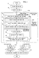
- FIG. 1 shows a flow of procedures for design and development of LSI in accordance with the invention.
- the present flow shown in FIG. 1 is facilitated in manufacture to enable the architecture design at the high-level stage of design and is characterized by adding a simulation platform structuring process and a bus performance evaluation process (see step A15). Details of these processes will be described below.
- step A1 algorithms are designed for logic circuits, devices and systems to be manufactured.
- step A2 verification is made as to whether the algorithms are made correctly or not.
- a simulation platform is structured to perform architecture design by using sources, which are used in the aforementioned algorithm design. Namely, in the simulation platform structuring process, the flow proceeds to step A3 to effect isolation of the hardware and software.
- step A4 an evaluation function is created. Herein, it is satisfactory that the evaluation function has an operation of counting a certain value.
- step A5 variables loaded onto the bus interconnecting between the hardware and software are being selected. Then, the flow proceeds to step A6 in which sources that are used in the algorithm design are modified by executing the created evaluation function when data are written to the variables loaded onto the bus, in other words, when data transfer is effected on the bus that is a subject of evaluation (hereinafter, simply referred to as the 'evaluated' bus). In response to modifications of the sources, the simulation platform for use in the architecture design is structured again.
- step A8 bus traffic is calculated by the prescribed method, which depends on the created evaluation function.
- a processing rate requested by a main function is already known.
- the bus traffic is calculated with respect to the processing rate of the evaluated bus in step A9.
- bus traffic that is calculated in response to the processing rate, it is possible to check validity with respect to isolation of the hardware and software and a bus configuration. If the validity check causes a change of the bus, the sources that are described by the general purpose high-level language such as the C language and C++ language are modified, then, the simulation platform is structured again and the performance evaluation is performed again. That is, the present procedures provide a feedback loop (see step A16) for feeding back the result of the performance evaluation of the bus. Due to provision of such a feedback loop, it is possible to actualize the architecture design at the high-level stage of design.
- step A15 After completion of the architecture design in step A15, the flow proceeds to the hardware design (H/W design) and the software design (S/W design) respectively.
- sources having equivalent functions of the algorithm(s) are generally described by the HDL (i.e., Hardware Description Language), then, composition of circuitry is performed in step A10.
- step A11 verification is made as to whether the sources operate normally or not.
- step A12 verification is made as to whether the sources operate normally or not.
- step A13 verification is made as to whether the sources operate normally or not.
- step A14 cooperative verification is performed on unification of the hardware and software.
- the architecture design is already completed at the high-level stage of design. This places the cooperative verification as one type of simulation for making operational confirmation only, in which no design is newly made. Namely, this eliminates the necessity to provide feedback loops being derived from the cooperative verification.
- FIG. 2 shows a list form representing a bus performance evaluation method in accordance with the first embodiment of the invention.
- three variables namely 'a', 'b' and 'c' being loaded onto the evaluated bus, wherein all of the variables are subjected to global definition.
- an evaluation function 'BUS0()' and a local variable 'bus0'.
- the evaluation function increments a static variable i to provide a return value.
- the local variable bus0 stores the return value from the evaluation function BUS0(). Namely, it represents a number of times in effecting data transfer on the evaluated bus.
- the same number of bits are set to binary representations of the three variables a, b, c being loaded onto the evaluated bus.
- the number of bits of each variable is smaller than the number of lines (or bits) of the evaluated bus.
- the first embodiment shown in FIG. 2 is designed to certainly execute the evaluation function BUS0() when data are written to the variables a, b, c loaded onto the evaluated bus. So, the evaluation function BUS0() is embedded subsequent to (or just after) the variables to which data are written respectively. Every time the evaluation function BUS0() is executed, the static variable i is incremented to provide a return value. The return value from the evaluation function BUS0() represents the number of times in writing data to the variables loaded onto the evaluated bus.
- bus traffic for the processing rate (number of times in effecting data transfer) / (processing rate)
- FIG. 3 shows an example of the 'restructured' simulation platform.
- the variable b is regarded as one that is not to be loaded onto the evaluated bus because of result of the performance evaluation of the bus. That is, the restructured simulation platform has only two variables a, b that are being loaded onto the evaluated bus. Since the variable b is not loaded onto the bus, the evaluation function BUS0() is not embedded subsequent to the variable b to which data is written. In contrast, the evaluation function BUS0() is certainly embedded subsequent to the variables a, c to which data are written respectively. Thus, the evaluation function BUS0() is certainly executed just after the variables a, c to which the data are written respectively.
- FIG. 4 shows a flow of steps that are performed by a computer system realizing the aforementioned bus performance evaluation method shown in FIG. 1.
- step C1 the flow firstly proceeds to step C1 in which a specific evaluation function is created. It is satisfactory that the evaluation function meets an operation of incrementing a certain value.
- the algorithm design uses sources that are described by the C language or C++ language.
- step C2 the system reads the sources line by line while effecting syntax analysis.
- step C3 a decision is made as to whether the read sources describe operations of writing data to the variables loaded onto the evaluated bus or not. If so, the flow proceeds to step C4 in which the evaluation function is embedded subsequent to the variables to which the data are written respectively. Due to the aforementioned works, the evaluation function is certainly executed when the data are written to the variables loaded onto the evaluated bus, in other words, when data transfer is caused on the evaluated bus.
- step C5 a decision is made as to whether description of the sources reading in the aforementioned works is completed up to the last line of the sources originally used in the algorithm design or not. Thus, modification is effected on the sources originally used in the algorithm design. After the modification proceeds to the last line of the sources used in the algorithm design, the flow proceeds to step C6 in which the system compiles the modified sources to structure the simulation platform for use in the architecture design.
- step C7 bus traffic is calculated for the evaluated bus by execution of the simulation platform. Because the processing rate requested by the main function is already known, the bus traffic for the processing rate is produced so that performance evaluation is performed on the evaluated bus in step C8.
- Figures 5 to 10 show examples of list forms representing the bus performance evaluation methods in accordance with other embodiments of the invention. Next, those embodiments will be described in detail in comparison with the aforementioned first embodiment shown in FIG. 2.
- FIG. 5 shows the bus performance evaluation method of the second embodiment that has tree variables a, b and c, which are loaded on the evaluated bus and all of which are locally defined.
- an evaluation function BUS0() and a local variable bus0().
- the evaluation function increments a static variable i to provide a return value.
- the local variable bus0() stores the return value from the evaluation function BUS0(). That is, it represents a number of times in effecting data transfer on the evaluated bus.
- All of the variables a, b and c consist of the same number of bits, which is smaller than a number of lines (or bits) of the evaluated bus.
- a main difference between the first embodiment of FIG. 2 and the second embodiment of FIG. 5 lies in manners of definition of the variables, that is, the variables loaded onto the evaluated bus are not defined globally but defined locally in FIG. 5.
- bus traffic for its processing rate is calculated in accordance with the aforementioned equation (1).
- the second embodiment is designed such that the variables loaded onto the evaluated bus are not defined globally but are defined locally, it proceeds to calculation of the bus traffic for the processing rate and performance evaluation of the bus, then, it feeds back the result of the performance evaluation to structuring of the simulation platform. Therefore, as similar to the first embodiment, the second embodiment allows the architecture design to be effected at the high-level stage of design.
- FIG. 6 shows the bus performance evaluation method of the third embodiment that has three variables a, b and c, which are loaded onto the evaluated bus and all of which are defined globally.
- an evaluation function BUS0() and a local variable bus0().
- the evaluation function increments a static variable i to provide a return value.
- the local variable bus0() stores the return value from the evaluation function BUS0(). That is, it represents a number of times in effecting data transfer on the evaluated bus.
- All of the variables a, b and c consist of the same number of bits, which is smaller than a number of lines (or bits) of the evaluated bus.
- a main difference between the first embodiment of FIG. 2 and the third embodiment of FIG. 6 lies in manners of embedding of the evaluation function BUS0(), that is, the evaluation function is embedded just before the variables to which data are written respectively.
- the evaluation function is certainly performed when the data are written to the variables respectively, in other words, when data transfer is effected on the evaluated bus.
- the third embodiment performs the performance evaluation upon calculation of the bus traffic for the processing rate by the aforementioned equation (1).
- the third embodiment is designed such that the evaluation function BUS0() is embedded just before the variables to which data are written respectively, in other words, it is designed such that the evaluation function BUS0() is to be certainly performed when data are written to the variables respectively or when data transfer is effected on the evaluated bus.
- the third embodiment proceeds to calculation of the bus traffic for the processing rate and performance evaluation of the bus, then, it feeds back the result of the performance evaluation to structuring of the simulation platform. Therefore, as similar to the first embodiment, the third embodiment allows the architecture design to be effected at the high-level stage of design.
- bus traffic for its processing rate (number of times in execution) ⁇ 4 / (processing rate)
- FIG. 7 shows the bus performance evaluation method of the fourth embodiment that has two variables a, b loaded onto the evaluated bus, wherein both of the variables are defined globally.
- an evaluation function BUS1() and a local variable bus 1.
- the evaluation function BUS 1() has two arguments, namely 'bit' and 'bus'. That is, it increments a static variable i by 'bit/bus' to provide a return value.
- the local variable bus1 stores the return value from the evaluation function BUS1(). That is, it represents a number of times in effecting data transfer on the evaluated bus.
- variable a loaded onto the evaluated bus consists of thirty-two bits while the variable b loaded onto the evaluated bus consists of sixteen bits, wherein the evaluated bus consists of eight bits.
- the fourth embodiment of FIG. 7 deals with two bits loaded onto the evaluated bus, wherein the two variables are configured by different numbers of bits, both of which are greater than the number of bits of the evaluated bus.
- the fourth embodiment of FIG. 7 is characterized by that the evaluation function having two arguments 'bit' and 'bus', and it increments the static variable i to provide a return value.
- bus traffic for its processing rate is calculated by the aforementioned equation (1).
- the fourth embodiment is designed such that the variables loaded onto the evaluated bus are configured by different numbers of bits, which are greater than the number of bits of the evaluated bus, it proceeds to calculation of the bus traffic for the processing rate and performance evaluation of the bus, then, it feeds back the result of the performance evaluation to structuring of the simulation platform. Therefore, as similar to the first embodiment, the fourth embodiment allows the architecture design to be effected at the high-level stage of design.
- FIG. 8 shows the bus performance evaluation method of the fifth embodiment that has two variables a, b loaded onto the evaluated bus, which are defined by specific arrays respectively.
- an evaluation function BUS0() and a local variable bus2.
- the evaluation function has an argument 'ele', so it increments a static variable i by 'ele' to provide a return value.
- the local variable bus2 stores the return value from the evaluation function BUS2(), so it represents a number of times in effecting data transfer on the evaluated bus.
- Both of the variables a, b loaded onto the evaluated bus consist of the same number of bits, which is smaller than a number of bits of the evaluated bus.
- the fifth embodiment of FIG. 8 is designed such that both of the variables loaded onto the evaluated bus are defined by specific arrays, and address transfer is effected in the main function.
- the fifth embodiment is characterized by that the evaluation function having an argument 'ele' increments the static variable i by 'ele' to provide a return value.
- bus traffic for its processing rate is calculated by the aforementioned equation (1).
- the fifth embodiment is designed such that the variables loaded onto the evaluated bus are defined by the specific arrays, and the address transfer is effected in the main function, the fifth embodiment proceeds to calculation of the bus traffic for the processing rate and performance evaluation of the bus, then, it feeds back the result of the performance evaluation to structuring of the simulation platform. Therefore, as similar to the first embodiment, the fifth embodiment allows the architecture design to be effected at the high-level stage of design.
- FIG. 9 shows the bus performance evaluation method of the sixth embodiment that has two variables a, b loaded onto the evaluated bus, wherein the variables are both defined globally.
- an evaluation function BUS3() and a global variable 'bus'.
- the evaluation function increments the global variable 'bus'.
- the global variable 'bus' represents a number of times in effecting data transfer on the evaluated bus.
- Both of the variables a, b consist of the same number of bits, which is smaller than a number of bits of the evaluated bus.
- the sixth embodiment of FIG. 9 is characterized by that the variables to be incremented by the evaluation function are defined globally.
- bus traffic for its processing rate is calculated by the foregoing equation (1).
- the sixth embodiment is designed such that the variables to be incremented by the evaluation function are defined globally, the sixth embodiment proceeds to calculation of the bus traffic for the processing rate and performance evaluation of the bus, then, it feeds back the result of the performance evaluation to structuring of the simulation platform. Therefore, as similar to the first embodiment, the sixth embodiment allows the architecture design to be effected at the high-level stage of design.
- FIG. 10 shows an example of a simulation platform that is structured by sources described by the C++ language.
- the simulation platform shown in FIG. 10 there are provided three buses, namely 'bus0', 'bus1' and 'bus2' which are subjected to BUS class definition as well as three variables a, b and c.
- the variable a is defined globally and is loaded onto the bus bus0.
- the variable b is defined locally and is loaded onto the bus bus1.
- the variable c is defined by a specific array and is loaded onto the bus bus2.
- a BUS class which has a function 'count()' for incrementing a member variable i by '1' as well as two arguments, namely 'bit' and 'bus'.
- a function 'Count_bit()' for incrementing the member variable i by 'bit/bus' and an argument 'ele'.
- a function 'count_hairetu()' for incrementing the member variable i by 'ele' is defined. Therefore, the member variable i within the BUS class represents a number of times in effecting data transfer on the evaluated bus.
- Both of the variables a, c loaded onto the evaluated bus consists of the same number of bits, which is smaller than numbers of bits of the buses bus0 and bus1 respectively.
- the variable b loaded onto the evaluated bus consists of thirty-two bits, while the bus bus1 consists of eight bits.
- the simulation platform of FIG. 10 is characterized by the sources being described by the C++ language.
- bus traffic for its processing rate is calculated by the aforementioned equation (1).
- simulation platform is structured using the sources described by the C++ language as shown in FIG. 10, it proceeds to calculation of the bus traffic for the processing rate and performance evaluation of the bus, then, it feeds back the result of the performance evaluation to restructuring of the simulation platform. Therefore, it is possible to carry out the architecture design at the high-level stage of design.
- this invention is designed such that when data transfer is caused on the bus interconnecting between the hardware and software to be evaluated, the sources that are used in the architecture design and are described by the general purpose high-level language such as the C language and C++ language are modified by executing the specific evaluation function, so that the simulation platform for use in the architecture design is structured. Then, simulation is performed using the structured simulation platform to calculate the bus traffic for the processing rate of the evaluated bus. Thus, it is possible to perform the bus performance evaluation at the high-level stage of design.
- this invention is characterized by placing the cooperative verification on the unification of the hardware and software as one type of simulation that merely performs operational confirmation. That is, it is possible to exclude actual designing steps from the cooperative verification, so it is possible to considerably reduce the time and cost that are needed for design and development of the logic circuits, systems and devices.
Landscapes
- Engineering & Computer Science (AREA)
- Theoretical Computer Science (AREA)
- Computer Hardware Design (AREA)
- Physics & Mathematics (AREA)
- General Engineering & Computer Science (AREA)
- General Physics & Mathematics (AREA)
- Evolutionary Computation (AREA)
- Geometry (AREA)
- Quality & Reliability (AREA)
- Design And Manufacture Of Integrated Circuits (AREA)
- Debugging And Monitoring (AREA)
Abstract
Description
- This invention is provided for verification of algorithms in order to facilitate architecture designs at high-level stages of design. Specifically, this invention relates to bus performance evaluation methods for algorithm descriptions in which evaluation is performed on performances of buses interconnecting between the hardware and software by use of sources described by general purpose high-level languages such as the C language and C++ language.
- Due to the recent developments of the semiconductor technologies, there are tendencies for the physical hardware system to be frequently actualized by a single LSI chip rather than by plural LSI chips arranged on boards. For this reason, signals of the LSI chips that are conventionally interconnected with external terminals are translated to internal signals and are incorporated within the LSI chips in these days. To verify the conventional systems using the boards, it is necessary to produce LSI devices specifically for use in evaluation that is performed as if all internal signals are interconnected with external terminals. However, it is troublesome for manufacturers to perform verification on the systems by using the specifically designed LSI devices. Actually, the recent developments raise a difficulty in which verification is difficult to perform using the foregoing boards.
- FIG. 11 shows a flow of steps showing the conventional procedures for the design and development of LSI (hereinafter, simply referred to as LSI design and development) in manufacture of logic circuits, systems and devices. Prior to the actual manufacturing, simulation platforms (or algorithms) are normally structured without consideration of distinctions between the hardware and software (see step B1). In step B2, verification is made as to whether the algorithms are correctly made or not. Next, isolation of the hardware and software is performed on the structured simulation platforms, which are divided into hardware elements and software elements respectively. The isolation of the hardware and software is made by experiments.
- In the hardware design (or H/W design), sources having equivalent functions of the algorithms are generally described by HDL (which stands for 'Hardware Description Language'), then, composition of circuitry is carried out (see step B3). In step B4, verification is made as to whether the sources operate normally or not. In the software design (or S/W design), sources having equivalent functions of the algorithms are generally described by the programming language having a CPU dependency (see step B5). In step B6, verification is made as to whether the sources operate normally or not. Lastly, cooperative verification is performed on combinations of the hardware and software (see step B7).
- Prior to the actual manufacturing of LSI, the procedures for the LSI design and development should meet some essential conditions raising requirements of the system simulation and bus performance evaluation as well as the architecture design in which isolation of the hardware and software is performed by simulation. Conventionally, the system simulation is performed by the cooperative verification on the unification of the hardware and software.
- Due to rapid increases in scales of integrated circuits being manufactured in these days, it becomes necessary to provide considerably large numbers of codes for use in description of the circuits to be created. This causes considerable reduction in simulation speed of the cooperative verification on descriptions using the HDL or other programming languages each having a CPU dependency. In practice, it becomes very difficult to perform the architecture design using the cooperative verification.
- In the architecture design using the cooperative verification, there may occur necessities of modifications on buses interconnecting between the hardware and software due to results of evaluation of performances of the buses. In that case, it is necessary to modify the HDL or other programming languages each having a CPU dependency (see steps B8, B9 in FIG. 11).
- Due to increasing numbers of codes for use in description of the circuits to be created, circuit descriptions must become more and more complicated, which in turn cause complicity in modifications of the circuit descriptions. That is, it takes much time and cost to perform operations regarding feedback loops being derived from results of the cooperative verification. Recently, there are tendencies in which periods for developments of LSI are considerably reduced while the circuit scales are increased more and more. To cope with such tendencies, the procedures of the LSI design and development should meet some essential conditions in which evaluation of performances of the buses interconnecting between the hardware and software and the architecture design are performed at high-level stages of design respectively.
- It is an object of the invention to provide a bus performance evaluation method for algorithm description by which it is possible to considerably reduce turnaround times in design of LSI by excluding unwanted operations regarding feedback loops derived from cooperative verification in the hardware design and software design. Basically, this invention provides improvements in procedures for the design and development of LSI. That is, after isolation of the hardware and software being effected with respect to sources described by the general purpose high-level language in algorithm design, an evaluation function is created to count traffic of the bus interconnecting between the hardware and software. The sources are modified such that the evaluation function is performed every time data (e.g., a variable) is loaded onto the bus. Then, evaluation is performed on the performance of the bus having a processing rate. Based on the bus traffic that is finally produced with respect to the processing rate, isolation of the hardware and software is optimally performed at the prescribed stage of the architecture design. Thus, it is possible to exclude the feedback loops regarding the isolation between the hardware and software from the cooperative verification after the actual coding. As a result, it is possible to considerably reduce the turnaround time in the design of LSI.
- More specifically, the LSI design and development in manufacture is actualized by algorithm design, architecture design, actual hardware and software design, and verification. Herein, the architecture design contains a simulation platform structuring process and a bus performance evaluation process, which are interconnected by a feedback loop. In the algorithm design, sources are described by the general purpose high-level language such as the C language and C++ language. In the simulation platform structuring process, the sources are subjected to isolation of the hardware and software, while an evaluation function is created to count bus traffic of the bus interconnecting between the hardware and software. Every time data is written to a pre-defined variable loaded onto the bus, the evaluation function is performed to modify the sources. Then, evaluation is performed on the performance of the bus, so that the bus traffic for its processing rate is finally produced. That is, result of the bus performance evaluation process is fed back to the simulation platform structuring process such that isolation of the hardware and software is optimized in response to the bus traffic for the processing rate of the bus. This results in exclusion of feedback loops derived from the cooperative verification after the actual coding, so it is possible to considerably reduce overall turnaround time of design.
- These and other objects, aspects and embodiments of the present invention will be described in more detail with reference to the following drawing figures, of which:
- FIG. 1 is a flowchart showing procedures for design and development of LSI in accordance with the invention;
- FIG. 2 shows a list form representing a bus performance evaluation method in accordance with a first embodiment of the invention;
- FIG. 3 shows a list form representing a simulation platform that is restructured in accordance with the first embodiment shown in FIG. 2;
- FIG. 4 is a flowchart showing procedures of works that are effected by the first embodiment shown in FIG. 2;
- FIG. 5 shows a list form representing a bus performance evaluation method in accordance with a second embodiment of the invention;
- FIG. 6 shows a list form representing a bus performance evaluation method in accordance with a third embodiment of the invention;
- FIG. 7 shows a list form representing a bus performance evaluation method in accordance with a fourth embodiment of the invention;
- FIG. 8 shows a list form representing a bus performance evaluation method in accordance with a fifth embodiment of the invention;
- FIG. 9 shows a list form representing a bus performance evaluation method in accordance with a sixth embodiment of the invention;
- FIG. 10 shows a list form representing a simulation platform that is structured using sources described by the C++ language; and
- FIG. 11 is a flowchart showing procedures for the conventional design and development of LSI.
-
- This invention will be described in further detail by way of examples with reference to the accompanying drawings.
- FIG. 1 shows a flow of procedures for design and development of LSI in accordance with the invention. As compared with the conventional flow of procedures for the LSI design and development that is described in conjunction with FIG. 11, the present flow shown in FIG. 1 is facilitated in manufacture to enable the architecture design at the high-level stage of design and is characterized by adding a simulation platform structuring process and a bus performance evaluation process (see step A15). Details of these processes will be described below.
- In step A1, algorithms are designed for logic circuits, devices and systems to be manufactured. In step A2, verification is made as to whether the algorithms are made correctly or not.
- Next, a simulation platform is structured to perform architecture design by using sources, which are used in the aforementioned algorithm design. Namely, in the simulation platform structuring process, the flow proceeds to step A3 to effect isolation of the hardware and software. In step A4, an evaluation function is created. Herein, it is satisfactory that the evaluation function has an operation of counting a certain value.
- In step A5, variables loaded onto the bus interconnecting between the hardware and software are being selected. Then, the flow proceeds to step A6 in which sources that are used in the algorithm design are modified by executing the created evaluation function when data are written to the variables loaded onto the bus, in other words, when data transfer is effected on the bus that is a subject of evaluation (hereinafter, simply referred to as the 'evaluated' bus). In response to modifications of the sources, the simulation platform for use in the architecture design is structured again.
- Next, evaluation is performed on the performance of the bus, which is a subject of evaluation, by using the structured simulation platform. That is, in the performance evaluation process, the flow proceeds to step A7 in which verification is performed using the structured simulation platform. In step A8, bus traffic is calculated by the prescribed method, which depends on the created evaluation function. Herein, a processing rate requested by a main function is already known. Hence, the bus traffic is calculated with respect to the processing rate of the evaluated bus in step A9.
- Using the bus traffic that is calculated in response to the processing rate, it is possible to check validity with respect to isolation of the hardware and software and a bus configuration. If the validity check causes a change of the bus, the sources that are described by the general purpose high-level language such as the C language and C++ language are modified, then, the simulation platform is structured again and the performance evaluation is performed again. That is, the present procedures provide a feedback loop (see step A16) for feeding back the result of the performance evaluation of the bus. Due to provision of such a feedback loop, it is possible to actualize the architecture design at the high-level stage of design.
- After completion of the architecture design in step A15, the flow proceeds to the hardware design (H/W design) and the software design (S/W design) respectively. In the hardware design, sources having equivalent functions of the algorithm(s) are generally described by the HDL (i.e., Hardware Description Language), then, composition of circuitry is performed in step A10. In step A11, verification is made as to whether the sources operate normally or not. In the software design, sources having equivalent functions of the algorithm(s) are generally described by the programming language having a CPU dependency in step A12. In step A13, verification is made as to whether the sources operate normally or not.
- In step A14, cooperative verification is performed on unification of the hardware and software. In the present flow of procedures for the design and development of LSI, the architecture design is already completed at the high-level stage of design. This places the cooperative verification as one type of simulation for making operational confirmation only, in which no design is newly made. Namely, this eliminates the necessity to provide feedback loops being derived from the cooperative verification.
- FIG. 2 shows a list form representing a bus performance evaluation method in accordance with the first embodiment of the invention. With reference to FIG. 2, there are provided three variables, namely 'a', 'b' and 'c' being loaded onto the evaluated bus, wherein all of the variables are subjected to global definition. In addition, there are provided an evaluation function 'BUS0()' and a local variable 'bus0'. Herein, the evaluation function increments a static variable i to provide a return value. The local variable bus0 stores the return value from the evaluation function BUS0(). Namely, it represents a number of times in effecting data transfer on the evaluated bus. The same number of bits are set to binary representations of the three variables a, b, c being loaded onto the evaluated bus. Herein, the number of bits of each variable is smaller than the number of lines (or bits) of the evaluated bus.
- The first embodiment shown in FIG. 2 is designed to certainly execute the evaluation function BUS0() when data are written to the variables a, b, c loaded onto the evaluated bus. So, the evaluation function BUS0() is embedded subsequent to (or just after) the variables to which data are written respectively. Every time the evaluation function BUS0() is executed, the static variable i is incremented to provide a return value. The return value from the evaluation function BUS0() represents the number of times in writing data to the variables loaded onto the evaluated bus.
- In addition, the number of times in writing the data to the variables loaded onto the evaluated bus represents a number of times in effecting data transfer on the evaluated bus, namely bus traffic. Because the processing rate requested by the main function is already known, it is possible to calculate the bus traffic for the processing rate and effect performance evaluation in accordance with the following equation (1).
- FIG. 3 shows an example of the 'restructured' simulation platform. With reference to the restructured simulation platform shown in FIG. 3, the variable b is regarded as one that is not to be loaded onto the evaluated bus because of result of the performance evaluation of the bus. That is, the restructured simulation platform has only two variables a, b that are being loaded onto the evaluated bus. Since the variable b is not loaded onto the bus, the evaluation function BUS0() is not embedded subsequent to the variable b to which data is written. In contrast, the evaluation function BUS0() is certainly embedded subsequent to the variables a, c to which data are written respectively. Thus, the evaluation function BUS0() is certainly executed just after the variables a, c to which the data are written respectively.
- After restructuring of the simulation platform, verification is performed by simulation. Then, the bus traffic for the processing rate is calculated again in accordance with the equation (1), so that evaluation is to be performed on the performance of the bus.
- Through the aforementioned operations, an average bus traffic is produced with respect to the data rate of the evaluated bus. Then, performance evaluation is performed on the bus, so that the result of the performance evaluation is fed back to structuring of the simulation platform. Hence, it is possible to actualize the architecture design at the high-level stage of design.
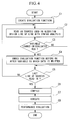
- FIG. 4 shows a flow of steps that are performed by a computer system realizing the aforementioned bus performance evaluation method shown in FIG. 1.
- With reference to FIG. 4, the flow firstly proceeds to step C1 in which a specific evaluation function is created. It is satisfactory that the evaluation function meets an operation of incrementing a certain value. Herein, the algorithm design uses sources that are described by the C language or C++ language. In step C2, the system reads the sources line by line while effecting syntax analysis.
- In step C3, a decision is made as to whether the read sources describe operations of writing data to the variables loaded onto the evaluated bus or not. If so, the flow proceeds to step C4 in which the evaluation function is embedded subsequent to the variables to which the data are written respectively. Due to the aforementioned works, the evaluation function is certainly executed when the data are written to the variables loaded onto the evaluated bus, in other words, when data transfer is caused on the evaluated bus.
- In step C5, a decision is made as to whether description of the sources reading in the aforementioned works is completed up to the last line of the sources originally used in the algorithm design or not. Thus, modification is effected on the sources originally used in the algorithm design. After the modification proceeds to the last line of the sources used in the algorithm design, the flow proceeds to step C6 in which the system compiles the modified sources to structure the simulation platform for use in the architecture design. In step C7, bus traffic is calculated for the evaluated bus by execution of the simulation platform. Because the processing rate requested by the main function is already known, the bus traffic for the processing rate is produced so that performance evaluation is performed on the evaluated bus in step C8.
- Figures 5 to 10 show examples of list forms representing the bus performance evaluation methods in accordance with other embodiments of the invention. Next, those embodiments will be described in detail in comparison with the aforementioned first embodiment shown in FIG. 2.
- FIG. 5 shows the bus performance evaluation method of the second embodiment that has tree variables a, b and c, which are loaded on the evaluated bus and all of which are locally defined. In addition, there are provided an evaluation function BUS0() and a local variable bus0(). The evaluation function increments a static variable i to provide a return value. The local variable bus0() stores the return value from the evaluation function BUS0(). That is, it represents a number of times in effecting data transfer on the evaluated bus.
- All of the variables a, b and c consist of the same number of bits, which is smaller than a number of lines (or bits) of the evaluated bus. A main difference between the first embodiment of FIG. 2 and the second embodiment of FIG. 5 lies in manners of definition of the variables, that is, the variables loaded onto the evaluated bus are not defined globally but defined locally in FIG. 5. To perform performance evaluation on the bus, bus traffic for its processing rate is calculated in accordance with the aforementioned equation (1).
- As the second embodiment is designed such that the variables loaded onto the evaluated bus are not defined globally but are defined locally, it proceeds to calculation of the bus traffic for the processing rate and performance evaluation of the bus, then, it feeds back the result of the performance evaluation to structuring of the simulation platform. Therefore, as similar to the first embodiment, the second embodiment allows the architecture design to be effected at the high-level stage of design.
- FIG. 6 shows the bus performance evaluation method of the third embodiment that has three variables a, b and c, which are loaded onto the evaluated bus and all of which are defined globally. In addition, there are provided an evaluation function BUS0() and a local variable bus0(). Herein, the evaluation function increments a static variable i to provide a return value. The local variable bus0() stores the return value from the evaluation function BUS0(). That is, it represents a number of times in effecting data transfer on the evaluated bus.
- All of the variables a, b and c consist of the same number of bits, which is smaller than a number of lines (or bits) of the evaluated bus. A main difference between the first embodiment of FIG. 2 and the third embodiment of FIG. 6 lies in manners of embedding of the evaluation function BUS0(), that is, the evaluation function is embedded just before the variables to which data are written respectively. Thus, the evaluation function is certainly performed when the data are written to the variables respectively, in other words, when data transfer is effected on the evaluated bus. Incidentally, the third embodiment performs the performance evaluation upon calculation of the bus traffic for the processing rate by the aforementioned equation (1).
- As described above, the third embodiment is designed such that the evaluation function BUS0() is embedded just before the variables to which data are written respectively, in other words, it is designed such that the evaluation function BUS0() is to be certainly performed when data are written to the variables respectively or when data transfer is effected on the evaluated bus. Herein, the third embodiment proceeds to calculation of the bus traffic for the processing rate and performance evaluation of the bus, then, it feeds back the result of the performance evaluation to structuring of the simulation platform. Therefore, as similar to the first embodiment, the third embodiment allows the architecture design to be effected at the high-level stage of design.
- Next, a description will be given with respect to the case where all of the variables a, b and c have the same number of bits, which is greater than the number of lines (or bits) of the evaluated bus. The description will be given with respect to the case where each of the variables a, b and c consists of n bits while the evaluated bus consists of m bits (where n≧m). For example, n is set to '32', and 'm' is set to '8'.
- In the aforementioned case, when data are written to the variables loaded onto the evaluated bus, data transfer is effected on the bus multiple times, a number of which is calculated by 'n/m', that is, four times. To perform the performance evaluation on the bus, bus traffic for its processing rate is calculated by the following equation (2).
- Next, further embodiments of the invention will be described with reference to Figures 7 to 10.
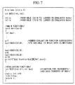
- FIG. 7 shows the bus performance evaluation method of the fourth embodiment that has two variables a, b loaded onto the evaluated bus, wherein both of the variables are defined globally. In addition, there are provided an evaluation function BUS1() and a local
variable bus 1. Herein, the evaluation function BUS 1() has two arguments, namely 'bit' and 'bus'. That is, it increments a static variable i by 'bit/bus' to provide a return value. The local variable bus1 stores the return value from the evaluation function BUS1(). That is, it represents a number of times in effecting data transfer on the evaluated bus. - Suppose that the variable a loaded onto the evaluated bus consists of thirty-two bits while the variable b loaded onto the evaluated bus consists of sixteen bits, wherein the evaluated bus consists of eight bits.
- Different from the foregoing first embodiment of FIG. 2, the fourth embodiment of FIG. 7 deals with two bits loaded onto the evaluated bus, wherein the two variables are configured by different numbers of bits, both of which are greater than the number of bits of the evaluated bus. In addition, the fourth embodiment of FIG. 7 is characterized by that the evaluation function having two arguments 'bit' and 'bus', and it increments the static variable i to provide a return value. To perform performance evaluation on the bus, bus traffic for its processing rate is calculated by the aforementioned equation (1).
- Although the fourth embodiment is designed such that the variables loaded onto the evaluated bus are configured by different numbers of bits, which are greater than the number of bits of the evaluated bus, it proceeds to calculation of the bus traffic for the processing rate and performance evaluation of the bus, then, it feeds back the result of the performance evaluation to structuring of the simulation platform. Therefore, as similar to the first embodiment, the fourth embodiment allows the architecture design to be effected at the high-level stage of design.
- FIG. 8 shows the bus performance evaluation method of the fifth embodiment that has two variables a, b loaded onto the evaluated bus, which are defined by specific arrays respectively. In addition, there are provided an evaluation function BUS0() and a local variable bus2. Herein, the evaluation function has an argument 'ele', so it increments a static variable i by 'ele' to provide a return value. The local variable bus2 stores the return value from the evaluation function BUS2(), so it represents a number of times in effecting data transfer on the evaluated bus.
- Both of the variables a, b loaded onto the evaluated bus consist of the same number of bits, which is smaller than a number of bits of the evaluated bus. Different from the first embodiment of FIG. 2, the fifth embodiment of FIG. 8 is designed such that both of the variables loaded onto the evaluated bus are defined by specific arrays, and address transfer is effected in the main function. In addition, the fifth embodiment is characterized by that the evaluation function having an argument 'ele' increments the static variable i by 'ele' to provide a return value.
- To perform performance evaluation on the bus, bus traffic for its processing rate is calculated by the aforementioned equation (1).
- Although the fifth embodiment is designed such that the variables loaded onto the evaluated bus are defined by the specific arrays, and the address transfer is effected in the main function, the fifth embodiment proceeds to calculation of the bus traffic for the processing rate and performance evaluation of the bus, then, it feeds back the result of the performance evaluation to structuring of the simulation platform. Therefore, as similar to the first embodiment, the fifth embodiment allows the architecture design to be effected at the high-level stage of design.
- FIG. 9 shows the bus performance evaluation method of the sixth embodiment that has two variables a, b loaded onto the evaluated bus, wherein the variables are both defined globally. In addition, there are provided an evaluation function BUS3() and a global variable 'bus'. The evaluation function increments the global variable 'bus'. The global variable 'bus' represents a number of times in effecting data transfer on the evaluated bus.
- Both of the variables a, b consist of the same number of bits, which is smaller than a number of bits of the evaluated bus. Different from the first embodiment of FIG. 1, the sixth embodiment of FIG. 9 is characterized by that the variables to be incremented by the evaluation function are defined globally.
- To perform performance evaluation on the bus, bus traffic for its processing rate is calculated by the foregoing equation (1).
- Although the sixth embodiment is designed such that the variables to be incremented by the evaluation function are defined globally, the sixth embodiment proceeds to calculation of the bus traffic for the processing rate and performance evaluation of the bus, then, it feeds back the result of the performance evaluation to structuring of the simulation platform. Therefore, as similar to the first embodiment, the sixth embodiment allows the architecture design to be effected at the high-level stage of design.
- FIG. 10 shows an example of a simulation platform that is structured by sources described by the C++ language.
- In the simulation platform shown in FIG. 10, there are provided three buses, namely 'bus0', 'bus1' and 'bus2' which are subjected to BUS class definition as well as three variables a, b and c. Herein, the variable a is defined globally and is loaded onto the bus bus0. The variable b is defined locally and is loaded onto the bus bus1. The variable c is defined by a specific array and is loaded onto the bus bus2.
- There is provided a BUS class, which has a function 'count()' for incrementing a member variable i by '1' as well as two arguments, namely 'bit' and 'bus'. In addition, there are provided a function 'Count_bit()' for incrementing the member variable i by 'bit/bus' and an argument 'ele'. Further, a function 'count_hairetu()' for incrementing the member variable i by 'ele' is defined. Therefore, the member variable i within the BUS class represents a number of times in effecting data transfer on the evaluated bus.
- Both of the variables a, c loaded onto the evaluated bus consists of the same number of bits, which is smaller than numbers of bits of the buses bus0 and bus1 respectively. In addition, the variable b loaded onto the evaluated bus consists of thirty-two bits, while the bus bus1 consists of eight bits.
- Different from the foregoing. embodiments (including the first embodiment of FIG. 2), the simulation platform of FIG. 10 is characterized by the sources being described by the C++ language. To perform performance evaluation on the bus, bus traffic for its processing rate is calculated by the aforementioned equation (1).
- Although the simulation platform is structured using the sources described by the C++ language as shown in FIG. 10, it proceeds to calculation of the bus traffic for the processing rate and performance evaluation of the bus, then, it feeds back the result of the performance evaluation to restructuring of the simulation platform. Therefore, it is possible to carry out the architecture design at the high-level stage of design.
- As described heretofore, this invention is designed such that when data transfer is caused on the bus interconnecting between the hardware and software to be evaluated, the sources that are used in the architecture design and are described by the general purpose high-level language such as the C language and C++ language are modified by executing the specific evaluation function, so that the simulation platform for use in the architecture design is structured. Then, simulation is performed using the structured simulation platform to calculate the bus traffic for the processing rate of the evaluated bus. Thus, it is possible to perform the bus performance evaluation at the high-level stage of design.
- Result of the bus performance evaluation is fed back to the sources that are used in verification of the algorithm(s). This enables the architecture design to be performed at the high-level stage of design. So, it is possible to reduce overall simulation time that is necessary for the architecture design. In addition, this invention is characterized by placing the cooperative verification on the unification of the hardware and software as one type of simulation that merely performs operational confirmation. That is, it is possible to exclude actual designing steps from the cooperative verification, so it is possible to considerably reduce the time and cost that are needed for design and development of the logic circuits, systems and devices.
- As described heretofore, this invention has a variety of effects and technical features, which will be described below.
- (1) When data are written to variables loaded onto the evaluated bus, sources that are described by the general purpose high-level language such as the C language and C++ language for use in the algorithm design are modified by executing a specific evaluation function for increment by a certain value, so that a simulation platform is structured. Hence, bus traffic is calculated in connection with the processing rate of the bus interconnecting between the hardware and software, so bus performance evaluation can be performed at the high-level stage of design in the LSI design and development. In addition, result of performance evaluation of the bus is fed back to structuring of the simulation platform, so it is possible to perform the architecture design at the high-level stage of design. Because the architecture design is performed using the sources that are described by the general purpose high-level language for use in the algorithm design, it is possible to considerably reduce overall simulation time for the architecture design. Generally speaking, as compared with the HDL, the C language and C++ language are increased in simulation speed to be approximately one-thousand times higher.
- (2) Because the architecture design is performed using the sources that are described by the general purpose high-level language, it is possible to simplify feedback procedures due to the architecture design. By optimally performing isolation of the hardware and software at the prescribed stage of the architecture design, it is possible to exclude feedback loops regarding the isolation of the hardware and software from the cooperative verification after the actual coding. This guarantees considerable reduction of the turnaround time of design. As compared with the HDL and other assembly languages, the C language and C++ language can be described using a relatively small number of codes. That is, those languages can be easily changed and modified according to needs.
- (3) This invention places the cooperative verification on unification of the hardware and software as one type of simulation for merely performing operational confirmation, wherein no design is newly performed. This brings exclusion of the feedback loops being derived from the cooperative verification. That is, it is possible to reduce a number of times in effecting simulation in RTL, so it is possible to considerably reduce overall time and cost for the design of circuitry. Such an effect becomes substantial as the scale of circuitry being manufactured increases.
-
- As this invention may be embodied in several forms without departing from the spirit of essential characteristics thereof, the present embodiments are therefore illustrative and not restrictive, since the scope of the invention is defined by the appended claims rather than by the description preceding them, and all changes that fall within metes and bounds of the claims, or equivalence of such metes and bounds are therefore intended to be embraced by the claims.
Claims (10)
- A bus performance evaluation method for algorithm description in which evaluation is performed on performance of a bus interconnecting between hardware and software by using sources described by a general purpose high-level language for verification of an algorithm, said bus performance evaluation method comprising the steps of:modifying the sources by executing a specific evaluation function when data transfer is caused on the bus; andin response to modified sources, structuring a simulation platform for use in an architecture design.
- A bus performance evaluation method for the algorithm description according to claim 1 further comprising the step of:
performing simulation using the simulation platform to allow calculation of bus traffic for a processing rate of the bus, so that the evaluation of the performance of the bus is performed at a high-level stage of design. - A bus performance evaluation method for the algorithm description according to claim 1 or 2 further comprising the step of:
feeding back result of the evaluation of the performance of the bus to the sources used in the verification of the algorithm, so that the architecture design is performed at a high-level stage of design. - A bus performance evaluation method for algorithm description in which evaluation is performed on performance of a bus interconnecting between hardware and software by using sources described by a general purpose high-level language for verification of an algorithm, said bus performance evaluation method comprising the steps of:structuring a simulation platform for use in an architecture design by using the sources;performing the evaluation of the performance of the bus by using the simulation platform;modifying the sources in response to result of the evaluation of the performance of the bus;restructuring the simulation platform in response to the modified sources; andperforming the evaluation again on the performance of the bus by using the restructured simulation platform.
- A bus performance evaluation method for the algorithm description according to claim 4 wherein structuring the simulation platform for use in an architecture design using the sources comprises the steps ofanalyzing the sources by prescribed units respectively to isolate a hardware portion and a software portion;creating an evaluation function for counting bus traffic of the bus; andeffecting syntax correction on the sources by executing the evaluation function every time data transfer is caused on the bus.
- A bus performance evaluation method for the algorithm description according to claim 4 or 5 wherein the evaluation is performed on the performance of the bus by using the evaluation function, so that in response to the bus traffic that is finally produced with respect to the processing rate of the bus, isolation of the hardware and software is optimized.
- A bus performance evaluation method for algorithm description in which evaluation is performed on performance of a bus interconnecting between hardware and software by using sources described by a general purpose high-level language, said bus performance evaluation method comprising the steps of:creating an evaluation function for counting bus traffic of the bus;sequentially reading in the sources line by line while effecting syntax analysis;making a determination as to whether description of the sources represent writing data to variables that are defined in advance and are loaded onto the bus to be evaluated;upon the determination, modifying the sources by using the evaluation function that is embedded just before or just after the variable to which the data is written;repeating the foregoing steps until the sources are completely read in and modified up to a last line;structuring a simulation platform for use in an architecture design by compiling the sources being modified;performing calculation on the bus traffic for the bus by executing the simulation platform;producing the bus traffic with regard to a processing rate of the bus that is already known; andperforming the evaluation on the performance of the bus in response to the bus traffic being produced.
- A bus performance evaluation method for the algorithm description according to claim 7 wherein the variables loaded onto the bus consist of n bits while the bus consists of m bits (where n, m are both integral numbers, and n≦m), so that the bus traffic for the processing rate is produced such that a number of times in effecting data transfer on the bus is multiplied by n/m and is then divided by the processing rate.
- A bus performance evaluation method according to any one of the preceding claims wherein the general purpose high-level language is C language or C++ language.
- A bus performance evaluation method according to any one of the preceding claims wherein the evaluation function is to increment a pre-defined variable loaded onto the bus.
Applications Claiming Priority (2)
| Application Number | Priority Date | Filing Date | Title |
|---|---|---|---|
| JP2000166630A JP2001344287A (en) | 2000-06-02 | 2000-06-02 | Bus Performance Evaluation Method in Algorithm Description |
| JP2000166630 | 2000-06-02 |
Publications (2)
| Publication Number | Publication Date |
|---|---|
| EP1160697A2 true EP1160697A2 (en) | 2001-12-05 |
| EP1160697A3 EP1160697A3 (en) | 2003-04-23 |
Family
ID=18669919
Family Applications (1)
| Application Number | Title | Priority Date | Filing Date |
|---|---|---|---|
| EP01113431A Withdrawn EP1160697A3 (en) | 2000-06-02 | 2001-06-01 | Bus performance evaluation method for algorithm description |
Country Status (3)
| Country | Link |
|---|---|
| US (1) | US7366647B2 (en) |
| EP (1) | EP1160697A3 (en) |
| JP (1) | JP2001344287A (en) |
Cited By (2)
| Publication number | Priority date | Publication date | Assignee | Title |
|---|---|---|---|---|
| EP1507222A1 (en) * | 2002-05-30 | 2005-02-16 | NEC Electronics Corporation | System large scale integrated circuit (LSI) designing method |
| CN110362438A (en) * | 2019-07-18 | 2019-10-22 | 浪潮商用机器有限公司 | A kind of bus performance detection method, device, equipment and readable storage medium storing program for executing |
Families Citing this family (9)
| Publication number | Priority date | Publication date | Assignee | Title |
|---|---|---|---|---|
| JP2006113934A (en) * | 2004-10-18 | 2006-04-27 | Hitachi Ltd | Program development support apparatus, program development support method, and program |
| JP2007310449A (en) * | 2006-05-16 | 2007-11-29 | Fujitsu Ltd | Model generation program and model generation method for software / hardware co-design |
| FR2911980A1 (en) * | 2007-01-30 | 2008-08-01 | Thales Sa | METHOD FOR DESIGNING A SYSTEM COMPRISING MATERIAL COMPONENTS AND SOFTWARE |
| JP5034955B2 (en) * | 2008-01-08 | 2012-09-26 | 富士通株式会社 | Performance evaluation simulation apparatus, performance evaluation simulation method, and performance evaluation simulation program |
| JP5200675B2 (en) * | 2008-06-11 | 2013-06-05 | 富士通株式会社 | SIMULATION DEVICE, SIMULATION METHOD, SIMULATION PROGRAM, AND COMPUTER-READABLE RECORDING MEDIUM CONTAINING THE PROGRAM |
| JP5903814B2 (en) * | 2011-09-15 | 2016-04-13 | 日本電気株式会社 | Semiconductor circuit performance estimation apparatus, method and program thereof |
| US8938535B2 (en) * | 2012-06-01 | 2015-01-20 | National Chiao Tung University | System for real traffic replay over wireless networks |
| EP3405866A4 (en) * | 2016-01-22 | 2019-08-07 | Sony Interactive Entertainment Inc. | SIMULATION OF PATRIMONIAL BUS BEHAVIOR FOR RETROCOMPATIBILITY |
| CN106020720B (en) * | 2016-05-16 | 2018-12-14 | 浪潮电子信息产业股份有限公司 | Method for optimizing IO performance of Smart Rack node |
Family Cites Families (8)
| Publication number | Priority date | Publication date | Assignee | Title |
|---|---|---|---|---|
| US5535331A (en) * | 1987-09-04 | 1996-07-09 | Texas Instruments Incorporated | Processor condition sensing circuits, systems and methods |
| US5555201A (en) * | 1990-04-06 | 1996-09-10 | Lsi Logic Corporation | Method and system for creating and validating low level description of electronic design from higher level, behavior-oriented description, including interactive system for hierarchical display of control and dataflow information |
| US5604895A (en) * | 1994-02-22 | 1997-02-18 | Motorola Inc. | Method and apparatus for inserting computer code into a high level language (HLL) software model of an electrical circuit to monitor test coverage of the software model when exposed to test inputs |
| US5768567A (en) * | 1996-05-14 | 1998-06-16 | Mentor Graphics Corporation | Optimizing hardware and software co-simulator |
| US6321366B1 (en) * | 1997-05-02 | 2001-11-20 | Axis Systems, Inc. | Timing-insensitive glitch-free logic system and method |
| EP1145159A3 (en) * | 1998-09-30 | 2002-07-10 | Cadence Design Systems, Inc. | Block based design methodology |
| JP4077578B2 (en) * | 1999-04-30 | 2008-04-16 | 松下電器産業株式会社 | Integrated circuit device design method |
| US6694488B1 (en) * | 2000-03-03 | 2004-02-17 | Nec Corporation | System for the design of high-performance communication architecture for system-on-chips using communication architecture tuners |
-
2000
- 2000-06-02 JP JP2000166630A patent/JP2001344287A/en active Pending
-
2001
- 2001-06-01 US US09/872,091 patent/US7366647B2/en not_active Expired - Fee Related
- 2001-06-01 EP EP01113431A patent/EP1160697A3/en not_active Withdrawn
Non-Patent Citations (2)
| Title |
|---|
| O'NILS M; ET AL: "Interactive hardware-software partitioning and memory allocation based on data transfer profiling", INTERNATIONAL CONFERENCE ON RECENT ADVANCES IN MECHATRONICS, vol. 1, 14 August 1995 (1995-08-14), pages 447 - 452, XP002239915 * |
| TAMMEMÄE K ET AL: "AKKA: A Tool-kit for Cosynthesis and Prototyping", IEE DIGEST - COLLOQUIM ON HARDWARE-SOFTWARE COSYNTHESIS FOR RECONFIGURABLE SYSTEMS, vol. 96, no. 036, February 1996 (1996-02-01), pages 8/1 - 8/8, XP002244550 * |
Cited By (4)
| Publication number | Priority date | Publication date | Assignee | Title |
|---|---|---|---|---|
| EP1507222A1 (en) * | 2002-05-30 | 2005-02-16 | NEC Electronics Corporation | System large scale integrated circuit (LSI) designing method |
| US7124311B2 (en) | 2002-05-30 | 2006-10-17 | Nec Electronics Corporation | Method for controlling processor in active/standby mode by third decoder based on instructions sent to a first decoder and the third decoder |
| CN110362438A (en) * | 2019-07-18 | 2019-10-22 | 浪潮商用机器有限公司 | A kind of bus performance detection method, device, equipment and readable storage medium storing program for executing |
| CN110362438B (en) * | 2019-07-18 | 2023-05-05 | 浪潮商用机器有限公司 | A bus performance detection method, device, equipment and readable storage medium |
Also Published As
| Publication number | Publication date |
|---|---|
| EP1160697A3 (en) | 2003-04-23 |
| JP2001344287A (en) | 2001-12-14 |
| US7366647B2 (en) | 2008-04-29 |
| US20020066082A1 (en) | 2002-05-30 |
Similar Documents
| Publication | Publication Date | Title |
|---|---|---|
| US9250973B2 (en) | Apparatus and associated methodology of generating a multi-core communications topology | |
| US8214189B2 (en) | Performance evaluation simulation | |
| US20080046849A1 (en) | Method for changing physical layout data using virtual layer | |
| US20080244476A1 (en) | System and method for simultaneous optimization of multiple scenarios in an integrated circuit design | |
| US20080034338A1 (en) | Timing analysis method and device | |
| EP1160697A2 (en) | Bus performance evaluation method for algorithm description | |
| US20060101367A1 (en) | Design method of semiconductor device and semiconductor device | |
| US20040078180A1 (en) | Method for automatically decomposing dynamic system models into submodels | |
| US6988266B2 (en) | Method of transforming variable loops into constant loops | |
| US7849429B2 (en) | Methods for conserving memory in statistical static timing analysis | |
| US6775810B2 (en) | Boosting simulation performance by dynamically customizing segmented object codes based on stimulus coverage | |
| US8782589B1 (en) | Soft pin insertion during physical design | |
| US20100257499A1 (en) | Techniques for fast area-efficient incremental physical synthesis | |
| US9671447B2 (en) | Method of analyzing error rate in system-on-chip | |
| JP3193167B2 (en) | Logic synthesis system | |
| US5764527A (en) | Optimizing method for logic circuit and logic circuit optimizing system | |
| JP2002269162A (en) | Action synthesizing method | |
| JP2009169694A (en) | High level synthesis method, high level synthesis apparatus and program | |
| US7424418B1 (en) | Method for simulation with optimized kernels and debugging with unoptimized kernels | |
| US20110072404A1 (en) | Parallel Timing Analysis For Place-And-Route Operations | |
| US7181720B2 (en) | Process and device for circuit design by means of high-level synthesis | |
| US7571409B2 (en) | Circuit design device and circuit design program | |
| US20060059451A1 (en) | Method for creating and synthesizing multiple instances of a component from a single logical model | |
| US12450414B2 (en) | Systems and methods for generating placements for circuit designs using pyramidal flows | |
| JP4531715B2 (en) | System LSI design method and recording medium storing the same |
Legal Events
| Date | Code | Title | Description |
|---|---|---|---|
| PUAI | Public reference made under article 153(3) epc to a published international application that has entered the european phase |
Free format text: ORIGINAL CODE: 0009012 |
|
| AK | Designated contracting states |
Kind code of ref document: A2 Designated state(s): AT BE CH CY DE DK ES FI FR GB GR IE IT LI LU MC NL PT SE TR |
|
| AX | Request for extension of the european patent |
Free format text: AL;LT;LV;MK;RO;SI |
|
| PUAL | Search report despatched |
Free format text: ORIGINAL CODE: 0009013 |
|
| AK | Designated contracting states |
Designated state(s): AT BE CH CY DE DK ES FI FR GB GR IE IT LI LU MC NL PT SE TR |
|
| AX | Request for extension of the european patent |
Extension state: AL LT LV MK RO SI |
|
| RAP1 | Party data changed (applicant data changed or rights of an application transferred) |
Owner name: NEC ELECTRONICS CORPORATION |
|
| 17P | Request for examination filed |
Effective date: 20030604 |
|
| 17Q | First examination report despatched |
Effective date: 20030710 |
|
| AKX | Designation fees paid |
Designated state(s): BE DE |
|
| 17Q | First examination report despatched |
Effective date: 20030710 |
|
| STAA | Information on the status of an ep patent application or granted ep patent |
Free format text: STATUS: THE APPLICATION IS DEEMED TO BE WITHDRAWN |
|
| 18D | Application deemed to be withdrawn |
Effective date: 20071212 |