EP1160573A2 - Microtitre plate and coupled multiple pipettor - Google Patents
Microtitre plate and coupled multiple pipettor Download PDFInfo
- Publication number
- EP1160573A2 EP1160573A2 EP01113301A EP01113301A EP1160573A2 EP 1160573 A2 EP1160573 A2 EP 1160573A2 EP 01113301 A EP01113301 A EP 01113301A EP 01113301 A EP01113301 A EP 01113301A EP 1160573 A2 EP1160573 A2 EP 1160573A2
- Authority
- EP
- European Patent Office
- Prior art keywords
- analyte
- pipette
- pipettes
- wells
- arrangement according
- Prior art date
- Legal status (The legal status is an assumption and is not a legal conclusion. Google has not performed a legal analysis and makes no representation as to the accuracy of the status listed.)
- Withdrawn
Links
Images

Classifications
-
- B—PERFORMING OPERATIONS; TRANSPORTING
- B01—PHYSICAL OR CHEMICAL PROCESSES OR APPARATUS IN GENERAL
- B01L—CHEMICAL OR PHYSICAL LABORATORY APPARATUS FOR GENERAL USE
- B01L3/00—Containers or dishes for laboratory use, e.g. laboratory glassware; Droppers
- B01L3/02—Burettes; Pipettes
- B01L3/021—Pipettes, i.e. with only one conduit for withdrawing and redistributing liquids
-
- G—PHYSICS
- G01—MEASURING; TESTING
- G01N—INVESTIGATING OR ANALYSING MATERIALS BY DETERMINING THEIR CHEMICAL OR PHYSICAL PROPERTIES
- G01N35/00—Automatic analysis not limited to methods or materials provided for in any single one of groups G01N1/00 - G01N33/00; Handling materials therefor
- G01N35/02—Automatic analysis not limited to methods or materials provided for in any single one of groups G01N1/00 - G01N33/00; Handling materials therefor using a plurality of sample containers moved by a conveyor system past one or more treatment or analysis stations
- G01N35/028—Automatic analysis not limited to methods or materials provided for in any single one of groups G01N1/00 - G01N33/00; Handling materials therefor using a plurality of sample containers moved by a conveyor system past one or more treatment or analysis stations having reaction cells in the form of microtitration plates
-
- G—PHYSICS
- G01—MEASURING; TESTING
- G01N—INVESTIGATING OR ANALYSING MATERIALS BY DETERMINING THEIR CHEMICAL OR PHYSICAL PROPERTIES
- G01N35/00—Automatic analysis not limited to methods or materials provided for in any single one of groups G01N1/00 - G01N33/00; Handling materials therefor
- G01N35/10—Devices for transferring samples or any liquids to, in, or from, the analysis apparatus, e.g. suction devices, injection devices
- G01N35/1065—Multiple transfer devices
- G01N35/1074—Multiple transfer devices arranged in a two-dimensional array
-
- B—PERFORMING OPERATIONS; TRANSPORTING
- B01—PHYSICAL OR CHEMICAL PROCESSES OR APPARATUS IN GENERAL
- B01L—CHEMICAL OR PHYSICAL LABORATORY APPARATUS FOR GENERAL USE
- B01L2300/00—Additional constructional details
- B01L2300/08—Geometry, shape and general structure
- B01L2300/0809—Geometry, shape and general structure rectangular shaped
- B01L2300/0829—Multi-well plates; Microtitration plates
-
- B—PERFORMING OPERATIONS; TRANSPORTING
- B01—PHYSICAL OR CHEMICAL PROCESSES OR APPARATUS IN GENERAL
- B01L—CHEMICAL OR PHYSICAL LABORATORY APPARATUS FOR GENERAL USE
- B01L2400/00—Moving or stopping fluids
- B01L2400/04—Moving fluids with specific forces or mechanical means
- B01L2400/0475—Moving fluids with specific forces or mechanical means specific mechanical means and fluid pressure
- B01L2400/0481—Moving fluids with specific forces or mechanical means specific mechanical means and fluid pressure squeezing of channels or chambers
-
- G—PHYSICS
- G01—MEASURING; TESTING
- G01N—INVESTIGATING OR ANALYSING MATERIALS BY DETERMINING THEIR CHEMICAL OR PHYSICAL PROPERTIES
- G01N35/00—Automatic analysis not limited to methods or materials provided for in any single one of groups G01N1/00 - G01N33/00; Handling materials therefor
- G01N35/10—Devices for transferring samples or any liquids to, in, or from, the analysis apparatus, e.g. suction devices, injection devices
- G01N2035/1027—General features of the devices
- G01N2035/1048—General features of the devices using the transfer device for another function
- G01N2035/1062—General features of the devices using the transfer device for another function for testing the liquid while it is in the transfer device
-
- Y—GENERAL TAGGING OF NEW TECHNOLOGICAL DEVELOPMENTS; GENERAL TAGGING OF CROSS-SECTIONAL TECHNOLOGIES SPANNING OVER SEVERAL SECTIONS OF THE IPC; TECHNICAL SUBJECTS COVERED BY FORMER USPC CROSS-REFERENCE ART COLLECTIONS [XRACs] AND DIGESTS
- Y10—TECHNICAL SUBJECTS COVERED BY FORMER USPC
- Y10T—TECHNICAL SUBJECTS COVERED BY FORMER US CLASSIFICATION
- Y10T436/00—Chemistry: analytical and immunological testing
- Y10T436/25—Chemistry: analytical and immunological testing including sample preparation
- Y10T436/25125—Digestion or removing interfering materials
-
- Y—GENERAL TAGGING OF NEW TECHNOLOGICAL DEVELOPMENTS; GENERAL TAGGING OF CROSS-SECTIONAL TECHNOLOGIES SPANNING OVER SEVERAL SECTIONS OF THE IPC; TECHNICAL SUBJECTS COVERED BY FORMER USPC CROSS-REFERENCE ART COLLECTIONS [XRACs] AND DIGESTS
- Y10—TECHNICAL SUBJECTS COVERED BY FORMER USPC
- Y10T—TECHNICAL SUBJECTS COVERED BY FORMER US CLASSIFICATION
- Y10T436/00—Chemistry: analytical and immunological testing
- Y10T436/25—Chemistry: analytical and immunological testing including sample preparation
- Y10T436/25375—Liberation or purification of sample or separation of material from a sample [e.g., filtering, centrifuging, etc.]
- Y10T436/255—Liberation or purification of sample or separation of material from a sample [e.g., filtering, centrifuging, etc.] including use of a solid sorbent, semipermeable membrane, or liquid extraction
-
- Y—GENERAL TAGGING OF NEW TECHNOLOGICAL DEVELOPMENTS; GENERAL TAGGING OF CROSS-SECTIONAL TECHNOLOGIES SPANNING OVER SEVERAL SECTIONS OF THE IPC; TECHNICAL SUBJECTS COVERED BY FORMER USPC CROSS-REFERENCE ART COLLECTIONS [XRACs] AND DIGESTS
- Y10—TECHNICAL SUBJECTS COVERED BY FORMER USPC
- Y10T—TECHNICAL SUBJECTS COVERED BY FORMER US CLASSIFICATION
- Y10T436/00—Chemistry: analytical and immunological testing
- Y10T436/25—Chemistry: analytical and immunological testing including sample preparation
- Y10T436/2575—Volumetric liquid transfer
Definitions
- the invention relates to an arrangement for receiving liquid Analytes.
- the arrangement known from [1] has a microtiter plate on with a variety of wells to accommodate a Analytes.
- microtiter plate is used, for example in various applications in medicine and Biotechnology for the inclusion of analytes Liquids, for example in the field of DNA analysis.
- each specialization analyte to be analyzed and introduced via a pipette usually over a large number as side by side So-called pipetting comb formed element, wherein for example, one pipette each for a pipetting comb for each well of a row of the microtiter plate is provided with depressions arranged in a matrix.
- the pipette is in accordance with the arrangement known from [1] via a hose with one of the respective pipettes clearly assigned pump with which the negative pressure is generated is coupled in such a way that the analyte by means of the pump can be sucked in via the corresponding pipette and accordingly again, controlled by the pump, into the Deepening can be introduced.
- Such a known microtiter plate has 96, for example Depressions with a size of 8 cm x 12 cm.
- Such a known microtiter plate can in principle any number, usually up to 384 wells exhibit.
- a disadvantage of the arrangement known from [1] is in particular to see in it that due to the high number of pumps it impractical until partially no longer possible on one such a small area of 8 cm x 12 cm for each well one line, i.e. for such a high number of pipettes to provide a separate pump.
- Another disadvantage is that the big one Number of required pumps with the corresponding arrangement of Hoses are very complicated and therefore prone to failure.
- Flow-Thru-Chip TM is in [2] described by means of which an analysis of the analyte regarding the existence of biological material in the Known analyte.
- the Flow-Thru-Chip TM an embodiment of an analysis chip, has a variety of channels through which the analyte is guided through the analysis chip, the surface of the Channels each with capture molecules, generally with molecules, which is the biological material accordingly sought, whose Existence in the analyte should be demonstrated, preferably can bind covalently.
- the DNA strands bind with the corresponding DNA capture molecules with opposite, i.e. complementary sequence.
- such an analysis chip is often used for analysis, i.e. for the detection of macromolecular biopolymers, including for example proteins or peptides or DNA strands a given frequency are to be understood, used.
- a membrane made of glass or Manufacture silicon that has a variety of pores with one constant diameter of 0.1 ⁇ m to 10 ⁇ m, for example also has 0.1 ⁇ m to 1 ⁇ m.
- the invention is therefore based on the problem of a Specify an arrangement for taking up liquid analytes at which also an increased number of wells in one Arrangement can be manufactured and operated more cost-effectively can, as this with an arrangement according to the prior art Technology is possible.
- An arrangement for taking up liquid analytes has one Microtiter plate with a variety of wells Uptake of an analyte.
- microtiter plate Under a microtiter plate is within the scope of the invention Plate with a variety of wells for receiving a To understand analytes, which are usually wells which are in a matrix form, i.e. in lines and Columns with usually constant distances from each other are arranged. However, it is in this context note that a microtiter plate is not on such Arrangement is limited, but that under the Invention to understand a microtiter plate is such that a structure with a large number of arbitrarily arranged Wells for holding a liquid analyte describes.
- a pipette For a well is a pipette, with a variety of Wells usually a variety of pipettes provided, each with an analyte from a pipette an associated depression, i.e. a depression above which the pipette is currently arranged, can be removed or can be introduced into this recess.
- the arrangement has a pump that has several Pipettes are coupled in such a way that one analyte each sucked in by means of the pump via an associated pipette can be done by operating the Analyte pump simultaneously sucked in or out of several wells several wells can be introduced.
- Analysis chips for analyzing the analyte are also provided, where each analysis chip is assigned to a specialization for the analysis of one introduced in the respective specialization Analyte.
- the area in contact with the analyte at least some of the analysis chips are of this type set up biological material to bind in molecules on the surface containing the analyte can be immobilized.
- the pipettes can be designed as a pipetting comb.
- the pipetting comb a first element and a has a second element coupled to the first element, the second element having the pipettes.
- a Plate may be arranged in which, according to one embodiment Invention the analysis chips for analyzing the analytes are arranged.
- the analysis chips for analyzing the analytes are arranged.
- each analysis chip each usually a recess for receiving each Analysis of one introduced in the respective specialization Analytes provided.
- At least the area that comes into contact with the analyte Part of the analysis chips can contain biological material have, which makes it possible in the analyte contained biological molecules, for example bind macromolecular biopolymers.
- Macromolecular biopolymers include these Invention, for example, proteins or peptides or even DNA molecules to understand.
- the Microtiter plate 96 wells or 384 wells for Recording one analyte at a time is provided.
- a baffle plate is provided for mixing the through the pipette filled analyts, which further extends the analysis result is improved because of the baffle plate in the Flow path of the analyte the mixture of the analyte and thus contacting the analyte with the capture molecules the surface of the fluid channels of the analysis chip is improved.
- these elements can be integrated in the analysis chip.
- the pump can be operated such that the Analyte sucked in by means of negative pressure generated in the pipette that is less than one in the pipette formed surface tension of the analyte.
- the invention can clearly be seen in that by providing a pump for several pipettes and their Design in such a way that each of several simultaneously Wells using a pump different analytes can be sucked in and analyzed accordingly Complexity and the cost of an arrangement for inclusion liquid analytes is significantly improved.
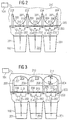
- FIG. 1 shows an arrangement 100 for taking up liquid analytes according to a first exemplary embodiment of the invention.
- the arrangement 100 has a microtiter plate 101 with a A variety of wells 102 for receiving usually different analytes, i.e. to be analyzed Liquids, on.
- a further plate 103 is on the microtiter plate 101 applied with the microtiter plate 101 by means of Screws (not shown) is coupled.
- the further one Plate 103 will be explained in more detail below.
- the pressure is within the others Plate 103, as described below, adjustable, i.e. it is in the corresponding room by the pump 104 Overpressure or underpressure freely adjustable.
- FIG. 2 shows an enlarged section 105 of the arrangement 100 from FIG. 1.
- an analyte 201 to be analyzed is usually introduced into the wells 102.
- the pipettes 202 arranged in the further plate 103 are arranged in the further plate 103 such that at Attach the further plate 103 to the microtiter plate 102 each using the screws, not shown Pipette 202 in an associated recess 102 and thus protrudes into the respective analyte 201.
- the pipettes 202 are on a lower plastic body 203 the further plate 103 is formed.
- the lower plastic body 203 is with an upper one Plastic body 204 coupled, for example glued.
- an intermediate plate 205 is arranged, in that of the analysis chips 206, according to this embodiment the analysis chip described in [2], also known as the Flow-Thru-Chip TM is referred to is introduced such that in each case an analysis chip 206 is provided for each well is.
- one analysis chip 206 each is provided for the analysis of an analyte 201, which in each case is contained in a depression 102 and according to an im further described methods on the pipette 202 and lower plastic body 203 through the analysis chip 206, i.e. through the fluid channels of the analysis chip 206 in the upper plastic body 204 is sucked.
- the analyte 201 is in each case with the Capture molecules on the surface of the fluid channels of the Analysis chips 206 brought into intimate contact.
- a membrane 207 is provided on the upper plastic body 204 .
- the upper plastic body 204 each a substantially the upper surface shape of the recess 102 corresponding space forms, each by side walls 208 of the upper plastic body 204 is formed.
- the upper plastic body 204 thus clearly shows Chambers 209 are formed, which are each limited by the Walls 208, the membrane 207 and the intermediate plate 205 with the integrated analysis chip 206.
- the membrane 207 is in each case an elastic membrane, For example, made of latex, which in by means of a pressure change one located above the upper plastic body 204 Room 210, which is coupled to the pump 104, changed can be.
- the space 210 can be filled with gas or with a liquid be, the membrane for the corresponding gas or Liquid with which space 210 is filled is not is permeable.
- the fluid channels in the Flow-Thru-Chip TM 206 are included biological material, i.e. with DNA capture molecules according to this embodiment shows that by means of the known Gold-sulfur coupling on the surface of the Liquid channels are bound in the analysis chip 206.
- the analyte to be analyzed has 201 DNA strands with a Sequence that corresponds to the DNA sequence of the DNA capture molecule is complementary, these DNA strands bind to the DNA capture molecules in the fluid channel of the analysis chip 206 covalent.
- the membrane 207 is thus clearly illustrated by a change in pressure, as shown in FIG . 3 , in accordance with the size of the membrane between the two extreme positions, symbolized in FIG. 3 by the tangents 211, 212 to the respectively maximum curved membrane.
- the amount of liquid pumped by means of the membrane 207 Analyte 201 should be significantly larger than that by the lower plastic body 203 for one pipette 202 each defined volume of a lower chamber 214 below the Analysis chips 206.
- the arrangement 100 is by means of maximum membrane position emptied in position 212.
- Flushing the arrangement by means of a flushing solution can in in the same way as the analysis.
- the second embodiment corresponds essentially to that first embodiment with the difference that none Membrane 207 is required.
- the pump 104 is operated such that a surface tension described below, which at the lower end of the respective pipette 202 in the Analyte forms, is not exceeded.
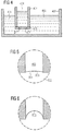
- FIG. 4 shows a pipette 401 which is immersed in a depression 402 and thereby in the analyte 403.
- the pipette 401 is as one Design tube with a diameter of about 1 cm and at its lower end 405 with a membrane 406 completed, for example glued, the membrane 406 a plurality of pores 407, but at least one pore 407, with a preferably constant diameter, according to this Embodiment contains a diameter of 10 microns.
- such a pore 407 may, for example, be one Have diameters from 0.1 ⁇ m to 100 ⁇ m.
- a membrane 407 such as it is known from [3], used from glass or silicon.
- the membrane 407 is designed to be hydrophilic.
- the analyte 403 now penetrates into the pores 407 of the membrane 406 one and can by a slight negative pressure, according to this Example of 0.03 bar in the Pipette 401 are sucked.
- Water is used as analyte and has a pore 407 has a radius of 10 ⁇ m, so for required pressure P a value of 0.29 bar.
- This control is usually not critical since, as above outlined, a vacuum of 0.03 bar is required to suck in the analyte, this pressure by one Power of ten is less than the critical pressure at which the surface tension would be overcome and it would become one Entry of air into the pore 407 could occur.
- hydrophobic membrane 407 it is of course also possible with one hydrophobic membrane 407, in a similar way a predeterminable Pump and gas using the arrangement described above liquid entry through the respective pore, generally by means of a capillary.
- This embodiment clearly illustrates one Detection is possible automatically, whether the entire analyte 403 from the respective specialization.
- FIG. 6 shows the enlarged section of a lower end of a pore 407 from Figure 4 at a negative pressure, which lies in a region which is on the verge of that air 502 enters the pore 407th
Landscapes
- Chemical & Material Sciences (AREA)
- Health & Medical Sciences (AREA)
- Biochemistry (AREA)
- Physics & Mathematics (AREA)
- Life Sciences & Earth Sciences (AREA)
- Analytical Chemistry (AREA)
- Chemical Kinetics & Catalysis (AREA)
- General Health & Medical Sciences (AREA)
- General Physics & Mathematics (AREA)
- Immunology (AREA)
- Pathology (AREA)
- Clinical Laboratory Science (AREA)
- Automatic Analysis And Handling Materials Therefor (AREA)
- Apparatus Associated With Microorganisms And Enzymes (AREA)
Abstract
Description
Die Erfindung betrifft eine Anordnung zur Aufnahme flüssiger Analyten.The invention relates to an arrangement for receiving liquid Analytes.
Eine solche Anordnung ist aus [1] bekannt.Such an arrangement is known from [1].
Die aus [1] bekannte Anordnung weist eine Mikrotiterplatte auf mit einer Vielzahl von Vertiefungen zur Aufnahme eines Analyten.The arrangement known from [1] has a microtiter plate on with a variety of wells to accommodate a Analytes.
Eine solche Mikrotiterplatte wird eingesetzt beispielsweise in unterschiedlichsten Anwendungen der Medizin und Biotechnologie zur Aufnahme von zu analysierenden Flüssigkeiten, beispielsweise im Bereich der DNA-Analyse.Such a microtiter plate is used, for example in various applications in medicine and Biotechnology for the inclusion of analytes Liquids, for example in the field of DNA analysis.
Üblicherweise wird in jeder Vertiefung ein unterschiedliches zu analysierendes Analyt eingebracht und über eine Pipette, üblicherweise über eine Vielzahl nebeneinander als sogenannter Pipettierkamm ausgebildetes Element, wobei beispielsweise bei einem Pipettierkamm jeweils eine Pipette für jeweils eine Vertiefung einer Zeile der Mikrotiterplatte mit matrixförmig angeordneten Vertiefungen vorgesehen ist.Usually there is a different one in each specialization analyte to be analyzed and introduced via a pipette, usually over a large number as side by side So-called pipetting comb formed element, wherein for example, one pipette each for a pipetting comb for each well of a row of the microtiter plate is provided with depressions arranged in a matrix.
Mittels einer Pipette wird jeweils aufgrund eines in der Pipette aufgebauten Unterdrucks ein Analyt aus der entsprechenden Vertiefung, in die das Analyt eingefüllt ist und in die die Pipette eingetaucht ist, entnommen, d.h. aufgesaugt.By means of a pipette, in each case on the basis of a Vacuum built up an analyte from the pipette corresponding recess in which the analyte is filled and into which the pipette is immersed, i.e. sucked up.
Die Pipette ist gemäß der aus [1] bekannten Anordnung jeweils über einen Schlauch mit einer der jeweiligen Pipette eindeutig zugeordneten Pumpe, mit der der Unterdruck erzeugt wird, derart gekuppelt, dass das Analyt mittels der Pumpe über die entsprechende Pipette angesaugt werden kann und entsprechend auch wieder, gesteuert von der Pumpe, in die Vertiefung eingebracht werden kann.The pipette is in accordance with the arrangement known from [1] via a hose with one of the respective pipettes clearly assigned pump with which the negative pressure is generated is coupled in such a way that the analyte by means of the pump can be sucked in via the corresponding pipette and accordingly again, controlled by the pump, into the Deepening can be introduced.
Eine solche bekannte Mikrotiterplatte weist beispielsweise 96 Vertiefungen bei einer Größe von 8 cm x 12 cm auf.Such a known microtiter plate has 96, for example Depressions with a size of 8 cm x 12 cm.
Eine solche bekannte Mikrotiterplatte kann aber grundsätzlich beliebig viele, üblicherweise bis zu 384 Vertiefungen aufweisen.Such a known microtiter plate can in principle any number, usually up to 384 wells exhibit.
Ein Nachteil der aus [1] bekannten Anordnung ist insbesondere darin zu sehen, dass aufgrund der hohen Anzahl von Pumpen es unpraktikabel bis teilweise nicht mehr möglich ist, auf einer derart kleinen Fläche von 8 cm x 12 cm für jede Vertiefung einer Zeile, d.h. für eine so hohe Anzahl von Pipetten jeweils eine eigene Pumpe vorzusehen.A disadvantage of the arrangement known from [1] is in particular to see in it that due to the high number of pumps it impractical until partially no longer possible on one such a small area of 8 cm x 12 cm for each well one line, i.e. for such a high number of pipettes to provide a separate pump.
Somit ist das Herstellen eines solchen Pipettenkamms und damit einer solchen Anordnung zur Aufnahme flüssiger Analyten sehr aufwendig und teuer.Thus, the manufacture of such a pipette comb and thus such an arrangement for taking up liquid analytes very complex and expensive.
Weiterhin ist anzumerken, dass bei der aus [1] bekannten Anordnung üblicherweise jeweils eine peristaltische Pumpe zum Ansaugen und Einbringen des Analyten aus bzw. in die jeweilige Vertiefung verwendet wird.It should also be noted that the one known from [1] Arrangement usually a peristaltic pump for Aspiration and introduction of the analyte from or into the respective recess is used.
Ein erheblicher Nachteil dieser bekannten Anordnung ist weiterhin darin zu sehen, dass für die Analyse üblicherweise eine Mindestmenge von einem zu analysierenden Analyt in der Größenordnung von 1 ml erforderlich ist.A significant disadvantage of this known arrangement is continue to be seen in that for analysis usually a minimum amount of one analyte to be analyzed in the The order of 1 ml is required.
Ein weiterer Nachteil ist darin zu sehen, dass die große Anzahl erforderlicher Pumpen mit zugehöriger Anordnung von Schläuchen sehr kompliziert und damit störanfällig ist.Another disadvantage is that the big one Number of required pumps with the corresponding arrangement of Hoses are very complicated and therefore prone to failure.
Weiterhin ist in [2] ein sogenannter Flow-Thru-Chip™ beschrieben, mittels dem eine Analyse des Analyten hinsichtlich der Existenz biologischen Materials in dem Analyt bekannt.Furthermore, a so-called Flow-Thru-Chip ™ is in [2] described by means of which an analysis of the analyte regarding the existence of biological material in the Known analyte.
Der Flow-Thru-Chip™, eine Ausgestaltung eines Analysechips, weist eine Vielzahl von Kanälen auf, durch die das Analyt durch den Analysechip geführt wird, wobei die Oberfläche der Kanäle jeweils mit Fängermolekülen, allgemein mit Molekülen, die das entsprechend gesuchte biologische Material, dessen Existenz in dem Analyt nachgewiesen werden soll, vorzugsweise kovalent binden können.The Flow-Thru-Chip ™, an embodiment of an analysis chip, has a variety of channels through which the analyte is guided through the analysis chip, the surface of the Channels each with capture molecules, generally with molecules, which is the biological material accordingly sought, whose Existence in the analyte should be demonstrated, preferably can bind covalently.
Ist als biologisches Material in dem Analyten ein DNA-Strang mit vorgegebener DNA-Sequenz zu ermitteln, so sind an der Oberfläche eines solchen Flüssigkeitskanals in dem Flow-Thru-Chip™ DNA-Fängermoleküle mit einer zu der zu ermittelnden DNA-Sequenz komplementären Sequenz aufgebracht.Is a DNA strand as a biological material in the analyte to be determined with a given DNA sequence Surface of such a liquid channel in the Flow-Thru-Chip ™ DNA capture molecules with one to be determined DNA sequence complementary sequence applied.
Ist in dem Analyten das DNA Material mit der gesuchten DNA-Sequenz vorhanden, so binden die DNA-Stränge mit den entsprechenden DNA-Fängermolekülen mit entgegengesetzter, d.h. komplementärer Sequenz.Is the DNA material in the analyte with the searched DNA sequence present, the DNA strands bind with the corresponding DNA capture molecules with opposite, i.e. complementary sequence.
Allgemein wird ein solcher Analysechip häufig zur Analyse, d.h. zum Nachweis makromolekularer Biopolymere, worunter beispielsweise Proteine oder Peptide oder auch DNA-Stränge einer jeweils vorgegebener Frequenz zu verstehen sind, eingesetzt.In general, such an analysis chip is often used for analysis, i.e. for the detection of macromolecular biopolymers, including for example proteins or peptides or DNA strands a given frequency are to be understood, used.
Ferner ist es aus [3] bekannt, eine Membran aus Glas oder Silizium herzustellen, die eine Vielzahl von Poren mit einem konstanten Durchmesser von 0,1 µm bis 10 µm, beispielsweise auch 0,1 µm bis 1 um aufweist.It is also known from [3], a membrane made of glass or Manufacture silicon that has a variety of pores with one constant diameter of 0.1 µm to 10 µm, for example also has 0.1 µm to 1 µm.
Somit liegt der Erfindung das Problem zugrunde, eine Anordnung zur Aufnahme flüssiger Analyten anzugeben, bei der auch eine erhöhte Anzahl von Vertiefungen in einer solchen Anordnung kostengünstiger hergestellt und betrieben werden kann, als dies mit einer Anordnung gemäß dem Stand der Technik möglich ist.The invention is therefore based on the problem of a Specify an arrangement for taking up liquid analytes at which also an increased number of wells in one Arrangement can be manufactured and operated more cost-effectively can, as this with an arrangement according to the prior art Technology is possible.
Das Problem wird durch die Anordnung zur Aufnahme flüssiger Analyten mit dem Merkmal gemäß dem unabhängigen Patentanspruch gelöst.The problem is made more fluid by the arrangement for taking up Analytes with the characteristic according to the independent Claim resolved.
Eine Anordnung zur Aufnahme flüssiger Analyten weist eine Mikrotiterplatte mit einer Vielzahl von Vertiefungen zur Aufnahme eines Analyten auf.An arrangement for taking up liquid analytes has one Microtiter plate with a variety of wells Uptake of an analyte.
Unter einer Mikrotiterplatte ist im Rahmen der Erfindung eine Platte mit einer Vielzahl von Vertiefungen zur Aufnahme eines Analyten zu verstehen, die üblicherweise Vertiefungen aufweisen, die in einer Matrixform, d.h. in Zeilen und Spalten mit üblicherweise konstanten Abständen von zueinander angeordnet sind. Es ist jedoch in diesem Zusammenhang anzumerken, dass eine Mikrotiterplatte nicht auf eine solche Anordnung beschränkt ist, sondern dass im Rahmen der Erfindung eine Mikrotiterplatte derart zu verstehen ist, dass sie eine Struktur mit einer Vielzahl beliebig angeordneter Vertiefungen zur Aufnahme eines flüssigen Analyten beschreibt.Under a microtiter plate is within the scope of the invention Plate with a variety of wells for receiving a To understand analytes, which are usually wells which are in a matrix form, i.e. in lines and Columns with usually constant distances from each other are arranged. However, it is in this context note that a microtiter plate is not on such Arrangement is limited, but that under the Invention to understand a microtiter plate is such that a structure with a large number of arbitrarily arranged Wells for holding a liquid analyte describes.
Für eine Vertiefung ist eine Pipette, bei einer Vielzahl von Vertiefungen üblicherweise einer Vielzahl von Pipetten vorgesehen, wobei jeweils mit einer Pipette ein Analyt aus einer zugehörigen Vertiefung, d.h. einer Vertiefung, über der die Pipette aktuell angeordnet ist, entnommen werden kann oder in diese Vertiefung eingebracht werden kann.For a well is a pipette, with a variety of Wells usually a variety of pipettes provided, each with an analyte from a pipette an associated depression, i.e. a depression above which the pipette is currently arranged, can be removed or can be introduced into this recess.
Ferner weist die Anordnung eine Pumpe auf, die mit mehreren Pipetten derart gekuppelt ist, dass jeweils ein Analyt mittels der Pumpe über eine zugehörige Pipette angesaugt werden kann und das durch Betätigen der Pumpe Analyte gleichzeitig aus mehreren Vertiefungen angesaugt oder in mehrere Vertiefungen eingebracht werden können. Furthermore, the arrangement has a pump that has several Pipettes are coupled in such a way that one analyte each sucked in by means of the pump via an associated pipette can be done by operating the Analyte pump simultaneously sucked in or out of several wells several wells can be introduced.
Auf diese Weise ist es möglich, mit einer sehr einfachen Anordnung, insbesondere einer verglichen mit der Anzahl von Vertiefungen erheblich verringerten Anzahl von Pumpen die Analyte anzusaugen, für den Fall, dass in dem Ansaugweg, d.h. in dem Flüssigkeitskanal innerhalb der Pipette ein Analysechip, beispielsweise der aus [2] beschriebene Flow-Thru-Chip™ mit auf den Oberflächen der Flüssigkeitskanäle aufgebrachten Fängermolekülen vorgesehen ist, zu gleicher Zeit jeweils mehrere, üblicherweise unterschiedliche Analyten zu analysieren.This way it is possible with a very simple one Arrangement, especially one compared to the number of Wells significantly reduced the number of pumps Aspirate analytes in the event that in the aspiration path, i.e. in the liquid channel inside the pipette Analysis chip, for example the Flow-Thru-Chip ™ described in [2] with on the surfaces of the liquid channels applied capture molecules is provided at the same Each time several, usually different analytes analyze.
Auf diese Weise wird die gesamte Anordnung erheblich kostengünstiger herstellbar und betreibbar.In this way, the entire arrangement becomes significant Can be manufactured and operated more cost-effectively.
Ferner ist die Anordnung erheblich weniger komplex und somit auch in erheblich geringeren Maßen störungsanfällig.Furthermore, the arrangement is considerably less complex and thus susceptible to failure even to a much lesser extent.
Ferner sind Analysechips zur Analyse des Analyt vorgesehen, wobei jeweils ein Analysechip einer Vertiefung zugeordnet ist zur Analyse eines in der jeweiligen Vertiefung eingebrachten Analyt. Die mit dem Analyt in Kontakt kommende Fläche zumindest eines Teils der Analysechips ist derart eingerichtet, dass biologisches Material zum Binden von in dem Analyten enthaltenen Molekülen auf der Fläche immobilisiert werden kann.Analysis chips for analyzing the analyte are also provided, where each analysis chip is assigned to a specialization for the analysis of one introduced in the respective specialization Analyte. The area in contact with the analyte at least some of the analysis chips are of this type set up biological material to bind in molecules on the surface containing the analyte can be immobilized.
Somit ist es erstmals auf einfache Weise möglich, biologisches Material auf robuste und dennoch kostengünstige und schnelle Weise parallelisiert zu analysieren.This makes it easy for the first time biological material on robust yet inexpensive and quickly analyze in parallel.
Die Pipetten können als Pipettierkamm ausgestaltet sein.The pipettes can be designed as a pipetting comb.
Gemäß einer weiteren Ausgestaltung der Erfindung ist es vorgesehen, dass der Pipettierkamm ein erstes Element und ein mit dem ersten Element gekuppeltes zweites Element aufweist, wobei das zweite Element die Pipetten aufweist. According to a further embodiment of the invention, it is provided that the pipetting comb a first element and a has a second element coupled to the first element, the second element having the pipettes.
Zwischen dem ersten Element und dem zweiten Element kann eine Platte angeordnet sein, in der gemäß einer Ausgestaltung der Erfindung die Analysechips zur Analyse der Analyten angeordnet sind. Für jeweils einen Analyse-Chip ist üblicherweise eine Vertiefung zur Aufnahme jeweils zur Analyse eines in der jeweiligen Vertiefung eingebrachten Analyten vorgesehen.Between the first element and the second element, a Plate may be arranged in which, according to one embodiment Invention the analysis chips for analyzing the analytes are arranged. For one analysis chip each usually a recess for receiving each Analysis of one introduced in the respective specialization Analytes provided.
Die mit dem Analyten in Kontakt kommende Fläche zumindest eines Teils der Analysechips kann biologisches Material aufweisen, wodurch es möglich wird, in dem Analyten enthaltene biologische Moleküle, beispielsweise makromolekulare Biopolymere zu binden.At least the area that comes into contact with the analyte Part of the analysis chips can contain biological material have, which makes it possible in the analyte contained biological molecules, for example bind macromolecular biopolymers.
Unter makromolekularen Biopolymeren sind im Rahmen dieser Erfindung beispielsweise Proteine oder Peptide oder auch DNA-Moleküle zu verstehen.Macromolecular biopolymers include these Invention, for example, proteins or peptides or even DNA molecules to understand.
Gemäß einer Ausgestaltung der Erfindung weist die Mikrotiterplatte 96 Vertiefungen oder 384 Vertiefungen zur Aufnahme jeweils eines Analyten auf.According to one embodiment of the invention, the Microtiter plate 96 wells or 384 wells for Recording one analyte at a time.
Über mindestens einen Teil der Pipetten kann jeweils eine elastische Membran dichtend angeordnet sein, so dass durch Verformung der Membran der Analyt aus der entsprechenden Vertiefung angesaugt oder in die entsprechende Vertiefung eingebracht werden kann.One can flow over at least some of the pipettes elastic membrane be arranged sealingly, so that by Deformation of the membrane of the analyte from the corresponding Well sucked in or into the corresponding well can be introduced.
Anschaulich bedeutete diese Ausgestaltung, dass mittels einer Verformung der Membran in der Pipette, d.h. zwischen der Membran und dem Analyten in der Pipette ein Unterdruck bzw. ein Überdruck erzeugt wird, wodurch eine Bewegung des Analyten innerhalb der Pipette, vorzugsweise durch den Analysechip hindurch, möglich ist. This configuration clearly meant that by means of a Deformation of the membrane in the pipette, i.e. between the Membrane and the analyte in the pipette a negative pressure or an overpressure is generated, causing movement of the Analytes within the pipette, preferably through the Analysis chip through, is possible.
Ein Vorteil bei Einsatz einer solchen Membran ist darin zu sehen, dass geschlossene Kammern gebildet werden, wodurch keine Dämpfe von den Analyten gebildet werden können, die möglicherweise für den Menschen giftig sein könnten.There is an advantage in using such a membrane see that closed chambers are formed, which no vapors can be generated by the analytes could be potentially toxic to humans.
Für jede Pipette ist gemäß einer Ausgestaltung der Erfindung eine Prellplatte vorgesehen zum Mischen des durch die Pipette gefüllten Analyts, wodurch das Analyseergebnis weiter verbessert wird, da aufgrund der Prellplatte in dem Strömungsweg des Analyten die Mischung des Analyten und damit das Inkontaktbringen des Analyts mit den Fängermolekülen auf der Oberfläche der Flüssigkeitskanäle des Analysechip weiter verbessert wird.For each pipette, according to an embodiment of the invention a baffle plate is provided for mixing the through the pipette filled analyts, which further extends the analysis result is improved because of the baffle plate in the Flow path of the analyte the mixture of the analyte and thus contacting the analyte with the capture molecules the surface of the fluid channels of the analysis chip is improved.
Weiterhin ist es gemäß einer Ausgestaltung der Erfindung vorgesehen für den Fall, dass eine Temperaturkontrolle in der Anordnung beispielsweise für chemische Reaktionen oder biologische Reaktionen erforderlich ist, dass in der Anordnung Messelemente und Heizelemente vorgesehen sind.Furthermore, it is according to an embodiment of the invention provided in the event that a temperature control in the Arrangement for example for chemical reactions or biological reactions that are required in the Arrangement measuring elements and heating elements are provided.
Diese Elemente können gemäß einer Ausgestaltung der Erfindung in dem Analysechip integriert sein.According to one embodiment of the invention, these elements can be integrated in the analysis chip.
Gemäß einer weiteren Ausgestaltung der Erfindung ist es vorgesehen, dass die Pumpe derart betreibbar ist, dass der Analyt mittels in der Pipette erzeugtem Unterdruck angesaugt wird, der geringer ist als eine in der Pipette möglicherweise gebildete Oberflächenspannung des Analyten.According to a further embodiment of the invention, it is provided that the pump can be operated such that the Analyte sucked in by means of negative pressure generated in the pipette that is less than one in the pipette formed surface tension of the analyte.
Auf diese Weise wird die Erkenntnis ausgenutzt, dass sich aufgrund des Kapillareffekts insbesondere bei derart geringen Dimensionen bei einer Pipette für eine Mikrotiterplatte ein sehr starker Kapillareffekt bildet, der zu einer sehr erheblichen Oberflächenspannung des aufzunehmenden Analyten führt, wenn der gesamte Analyt aus der Vertiefung angesaugt worden ist. In this way, the knowledge is exploited that due to the capillary effect, especially at such low levels Dimensions for a pipette for a microtiter plate very strong capillary effect that leads to a very considerable surface tension of the analyte to be absorbed leads when all of the analyte is sucked out of the well has been.
Auf diese Weise wird sehr einfach ohne eine zusätzlich erforderliche komplexe Steuerung vermieden, dass Luft oder ein anderes Gas in die Pipette angesaugt wird, nachdem das gesamte Analyt aus der jeweiligen Vertiefung aufgenommen worden ist.This way it becomes very easy without an additional one required complex control that avoided air or another gas is drawn into the pipette after that entire analyte taken from the respective well has been.
Es wird somit gewährleistet, dass immer genau soviel Analyt, allgemein Flüssigkeit und/oder Gas aufgenommen wird, wie zur Analyse erforderlich.This ensures that exactly as much analyte, generally liquid and / or gas is absorbed, such as Analysis required.
Anschaulich kann die Erfindung darin gesehen werden, dass durch Vorsehen einer Pumpe für mehrere Pipetten und deren Ausgestaltung derart, dass jeweils gleichzeitig aus mehreren Vertiefungen mittels einer Pumpe unterschiedliche Analyte angesaugt und entsprechend analysiert werden können, die Komplexität und die Kosten für eine Anordnung zur Aufnahme flüssiger Analyten erheblich verbessert wird.The invention can clearly be seen in that by providing a pump for several pipettes and their Design in such a way that each of several simultaneously Wells using a pump different analytes can be sucked in and analyzed accordingly Complexity and the cost of an arrangement for inclusion liquid analytes is significantly improved.
Ausführungsbeispiele der Erfindung sind in den Figuren dargestellt und werden im weiteren näher erläutert.Embodiments of the invention are in the figures shown and are explained in more detail below.
- Figur 1Figure 1
- eine Skizze einer Anordnung zur Aufnahme flüssiger Analyten gemäß einem ersten Ausführungsbeispiel der Erfindung;a sketch of an arrangement for taking liquid Analytes according to a first embodiment of the Invention;
- Figur 2Figure 2
- einen Ausschnitt der Anordnung aus Figur 1 im Querschnitt in einem Zustand, in dem sich das gesamte Analyt in den Vertiefungen befindet;a section of the arrangement of Figure 1 in Cross section in a state in which the whole Analyte located in the wells;
- Figur 3Figure 3
- den Ausschnitt aus Figur 2 in dem Zustand, dass ein Teil der Analyten durch die Pipetten in einen Aufnahmeraum angesaugt worden ist; the section of Figure 2 in the state that a Part of the analytes through the pipettes into one Recording room has been sucked in;
- Figur 4Figure 4
- einen Querschnitt durch eine Pipette, anhand der ein Prinzip, dem das zweite Ausführungsbeispiel der Erfindung zugrunde liegt, veranschaulicht ist;a cross section through a pipette, based on the Principle that the second embodiment of Invention underlying is illustrated;
- Figur 5Figure 5
- einen Querschnitt durch eine Pipette, anhand der ein Prinzip, dem das zweite Ausführungsbeispiel der Erfindung zugrunde liegt, veranschaulicht ist;a cross section through a pipette, based on the Principle that the second embodiment of Invention underlying is illustrated;
- Figur 6Figure 6
- einen Querschnitt durch eine Pipette, anhand der ein Prinzip, dem das zweite Ausführungsbeispiel der Erfindung zugrunde liegt, veranschaulicht ist.a cross section through a pipette, based on the Principle that the second embodiment of Invention is based, is illustrated.
Fig.1 zeigt eine Anordnung 100 zur Aufnahme flüssiger
Analyten gemäß einem ersten Ausführungsbeispiel der
Erfindung. 1 shows an
Die Anordnung 100 weist eine Mikrotiterplatte 101 mit einer
Vielzahl von Vertiefungen 102 zur Aufnahme von üblicherweise
jeweils unterschiedlichen Analyten, d.h. zu analysierenden
Flüssigkeiten, auf.The
Auf der Mikrotiterplatte 101 ist eine weitere Platte 103
aufgebracht, die mit der Mikrotiterplatte 101 mittels
Schrauben (nicht dargestellt) gekuppelt ist. Die weitere
Platte 103 wird im weiteren noch detailliert erläutert.A
Über der weiteren Platte 103, die entsprechend den
Vertiefungen 102 jeweils Pipetten, wie in Fig. 2 dargestellt,
aufweist, sind luftdicht mit einer auf der weiteren Platte
103 aufgebrachten Pumpe 104 gekuppelt.Over the
Mittels der Pumpe 104 ist der Druck innerhalb der weiteren
Platte 103, wie im weiteren beschrieben, einstellbar, d.h. es
ist in dem entsprechenden Raum durch die Pumpe 104 ein
Überdruck oder ein Unterdruck frei einstellbar. By means of the
Fig.2 zeigt einen vergrößerten Ausschnitt 105 der Anordnung
100 aus Fig.1. FIG. 2 shows an enlarged section 105 of the
Wie Fig.2 zu entnehmen ist, ist üblicherweise in die
Vertiefungen 102 jeweils ein zu analysierendes Analyt 201
eingebracht.As can be seen in FIG. 2 , an
Die in der weiteren Platte 103 angeordneten Pipetten 202 sind
derart in der weiteren Platte 103 angeordnet, dass bei
Befestigen der weiteren Platte 103 auf der Mikrotiterplatte
102 mittels der nicht dargestellten Schrauben jeweils eine
Pipette 202 in eine hierzu zugeordnete Vertiefung 102 und
damit in das jeweilige Analyt 201 hineinragt.The
Die Pipetten 202 sind an einem unteren Kunststoffkörper 203
der weiteren Platte 103 ausgebildet.The
Der untere Kunststoffkörper 203 ist mit einem oberen
Kunststoffkörper 204 gekuppelt, beispielsweise verklebt.The lower
Gemäß diesem Ausführungsbeispiel ist es vorgesehen, dass
zwischen dem unteren Kunststoffkörper 203 und dem oberen
Kunststoffkörper 204 eine Zwischenplatte 205 angeordnet ist,
in der der Analysechips 206, gemäß diesem Ausführungsbeispiel
der in [2] beschriebener Analysechip, der auch als Flow-Thru-Chip™
bezeichnet wird, eingebracht ist derart, dass jeweils
ein Analysechip 206 jeweils für eine Vertiefung vorgesehen
ist.According to this exemplary embodiment, it is provided that
between the lower
Anschaulich bedeutet dies, dass jeweils ein Analysechip 206
vorgesehen ist zur Analyse eines Analyts 201, welches jeweils
in einer Vertiefung 102 enthalten ist und gemäß einem im
weiteren beschriebenen Verfahren über die Pipette 202 und den
unteren Kunststoffkörper 203 durch den Analysechip 206, d.h.
durch die Flüssigkeitskanäle des Analysechips 206 in den
oberen Kunststoffkörper 204 eingesaugt wird. This clearly means that one
Auf diese Weise wird das Analyt 201 jeweils mit den
Fängermolekülen auf der Oberfläche der Flüssigkeitskanäle des
Analysechips 206 in innigen Kontakt gebracht.In this way, the
An dem oberen Kunststoffkörper 204 ist jeweils für eine
Vertiefung 102 eine Membran 207 vorgesehen.On the upper
Dies bedeutet, dass der obere Kunststoffkörper 204 jeweils
einen im wesentlichen der oberen Flächenform der Vertiefung
102 entsprechenden Raum bildet, der jeweils durch Seitenwände
208 des oberen Kunststoffkörpers 204 gebildet wird.This means that the upper
Anschaulich werden somit in dem oberen Kunststoffkörper 204
Kammern 209 gebildet, die jeweils begrenzt sind durch die
Wände 208, die Membran 207 sowie die Zwischenplatte 205 mit
dem integrierten Analysechip 206.The upper
Die Membran 207 ist jeweils eine elastische Membran,
beispielsweise aus Latex, die mittels einer Druckänderung in
einem sich über dem oberen Kunststoffkörper 204 befindenden
Raum 210, der mit der Pumpe 104 gekuppelt ist, verändert
werden kann.The
Der Raum 210 kann mit Gas oder mit einer Flüssigkeit gefüllt
sein, wobei die Membran für das entsprechende Gas oder die
Flüssigkeit, mit der der Raum 210 gefüllt ist, nicht
permeabel ist.The
Anschaulich wird somit aufgrund einer Druckveränderung in dem
Raum 210 die Membran 207 verformt, so dass eine
Druckveränderung in den jeweiligen Kammern 209 erzeugt wird,
wodurch das Analyt 201 über die Pipette 202 durch den
Analysechip 206 entweder angesaugt oder in die Vertiefung
zurückgedrückt wird. This becomes clear due to a change in pressure in the
Die Flüssigkeitskanäle in dem Flow-Thru-Chip™ 206 sind mit
biologischem Material, d.h. mit DNA-Fängermolekülen gemäß
diesem Ausführungsbeispiel belegt, die mittels der bekannten
Gold-Schwefel-Kopplung an der Oberfläche der
Flüssigkeitskanäle in dem Analysechip 206 gebunden sind.The fluid channels in the Flow-Thru-
Weist das zu analysierende Analyt 201 DNA-Stränge mit einer
Sequenz auf, die der DNA-Sequenz des DNA-Fängermoleküls
komplementär ist, so binden diese DNA-Stränge an die DNA-Fängermoleküle
in dem Flüssigkeitskanal des Analysechips 206
kovalent.The analyte to be analyzed has 201 DNA strands with a
Sequence that corresponds to the DNA sequence of the DNA capture molecule
is complementary, these DNA strands bind to the DNA capture molecules
in the fluid channel of the
Anschaulich wird somit die Membran 207 jeweils durch
Druckänderung, wie in Fig.3 dargestellt, entsprechend der
Größe der Membran zwischen den zwei Extrempositionen, in
Fig.3 symbolisiert durch die Tangenten 211, 212 an die
jeweils maximal gewölbten Membrane.The
Aufgrund der Verformung wird, wie oben beschrieben, das Analyt eingesaugt oder ausgegeben.Due to the deformation, as described above, the Analyte sucked in or released.
Weiterhin ist gemäß diesem Ausführungsbeispiel in dem unteren
Kunststoffkörper 203 für jede Pipette 202 jeweils zwischen
der Pipette 202 und der Zwischenplatte 205 eine Prellplatte
213 vorgesehen, durch die mittels einem Ausbilden einer
entsprechenden Strömungsform um die Prellplatte 213 herum ein
verbessertes Mischen des Analyts 201 gewährleistet ist.Furthermore, according to this embodiment is in the lower
Es sollte gemäß dieser Ausführungsform beachtet werden, dass
die mittels der Membran 207 umgepumpte Flüssigkeitsmenge des
Analyten 201 deutlich größer sein sollte als das durch den
unteren Kunststoffkörper 203 für jeweils eine Pipette 202
definierte Volumen einer unteren Kammer 214 unterhalb des
Analysechips 206.According to this embodiment, it should be noted that
the amount of liquid pumped by means of the
Nach erfolgter Analyse der Analyten, die beispielsweise im
Rahmen einer Hybridisierung typischerweise einige Stunden
andauert, wird die Anordnung 100 mittels Membran-Maximalstellung
in der Position 212 entleert.After analysis of the analytes, for example in
Hybridization typically takes a few hours
continues, the
Spülvorgänge der Anordnung mittels einer Spüllösung können in entsprechender Weise wie das Analysieren erfolgen.Flushing the arrangement by means of a flushing solution can in in the same way as the analysis.
Das zweite Ausführungsbeispiel entspricht im wesentlichen dem
ersten Ausführungsbeispiel mit dem Unterschied, dass keine
Membran 207 erforderlich ist.The second embodiment corresponds essentially to that
first embodiment with the difference that
Um zu gewährleisten, dass, nachdem das gesamte Analyt aus
einer jeweiligen Vertiefung angesaugt worden ist, keine Luft
oder ein anderes Gas aus der Vertiefung in die Pipette
eingesaugt wird, wird die Pumpe 104 derart betrieben, dass
eine im weiteren beschriebene Oberflächenspannung, die sich
an dem unteren Ende der jeweiligen Pipette 202 in dem
Analyten ausbildet, nicht überschritten wird.To ensure that after all the analyte is out
no air has been sucked into a respective depression
or another gas from the well into the pipette
is sucked in, the
Dieses Prinzip ist in Fig.4 veranschaulicht.This principle is illustrated in Fig.4 .
Fig.4 zeigt eine Pipette 401, die in eine Vertiefung 402 und
dabei in das Analyt 403 eingetaucht ist. 4 shows a
Ein in der Pipette 401 gebildeter Unterdruck ist in Fig.4
mittels eines Pfeils 404 symbolisiert.An underpressure formed in the
Die Pipette 401 gemäß diesem Ausführungsbeispiel ist als eine
Röhre mit einem Durchmesser von ungefähr 1 cm ausgestaltet
und an ihrem unteren Ende 405 mit einer Membran 406
abgeschlossen, beispielsweise verklebt, wobei die Membran 406
eine Vielzahl von Poren 407, mindestens jedoch eine Pore 407,
mit einem vorzugsweise konstanten Durchmesser, gemäß diesem
Ausführungsbeispiel einem Durchmesser von 10 µm, enthält. The
Allgemein kann eine solche Pore 407 beispielsweise einen Durchmesser von 0,1 µm bis 100 µm aufweisen.In general, such a pore 407 may, for example, be one Have diameters from 0.1 µm to 100 µm.
Gemäß diesem Ausführungsbeispiel wird eine Membran 407, wie sie aus [3] bekannt ist, aus Glas oder Silizium verwendet.According to this embodiment, a membrane 407, such as it is known from [3], used from glass or silicon.
Gemäß diesem Ausführungsbeispiel ist ohne Einschränkung der Allgemeingültigkeit angenommen, dass die Membran 407 hydrophil ausgestaltet ist.According to this embodiment, the It is generally assumed that the membrane 407 is designed to be hydrophilic.
Das Analyt 403 dringt nun in die Poren 407 der Membran 406
ein und kann durch einen geringen Unterdruck, gemäß diesem
Ausführungsbeispiel von beispielsweise 0,03 bar in die
Pipette 401 gesaugt werden.The
Ist die Vertiefung 402 geleert, d.h. ist das Analyt 403
vollständig in der Pipette 401 aufgenommen, so bildet sich,
wie in Fig.5 dargestellt, an jeder Porenöffnung 501 zwischen
dem Analyten 403 und der sich lediglich mehr in der
Vertiefung 402 befindlichen Luft 502 ein Meniskus 503.If the
Um den sich bildenden Meniskus 503 derart zu verformen, dass
ein Eintritt von Luft 502 in die Pore 407 möglich wird, muss
ein wesentlich stärkerer Unterdruck erzeugt werden als der
Unterdruck, der erforderlich ist, um das Analyt 403,
allgemein eine Flüssigkeit, in die Kapillare, d.h. in die
Pipette 401, einzusaugen.To deform the forming
Dieser erforderliche Druck P lässt sich gemäß folgender
Vorschrift abschätzen:
- mit S die Oberflächenspannung der jeweiligen
Flüssigkeit, d.h.
des Analyten 403, und - mit r der Radius der jeweiligen Pore 407, bezeichnet wird.
- with S the surface tension of the respective liquid, ie the
analyte 403, and - r denotes the radius of the respective pore 407.
Diese Größen sind für eine vorgegebene Anordnung üblicherweise bekannt.These sizes are for a given arrangement usually known.
Wird als Analyt Wasser verwendet und weist eine Pore 407 einen Radius von 10 µm auf, so ergibt sich für den erforderlichen Druck P ein Wert von 0,29 bar.Water is used as analyte and has a pore 407 has a radius of 10 µm, so for required pressure P a value of 0.29 bar.
Damit ein Lufteintritt in die Pore 407 verhindert werden kann, ist es erforderlich, einen Druck durch die Pumpe zu gewährleisten, der unterhalb dieses abgeschätzten Drucks liegt.This prevents air from entering the pore 407 can, it is necessary to apply pressure through the pump ensure that below this estimated pressure lies.
Diese Steuerung ist üblicherweise unkritisch, da, wie oben dargelegt, ein Unterdruck von 0,03 bar erforderlich ist, um das Analyt einzusaugen, wobei dieser Druck um eine Zehnerpotenz geringer ist als der kritische Druck, bei dem die Oberflächenspannung überwunden wäre und es zu einem Eintritt von Luft in die Pore 407 kommen könnte.This control is usually not critical since, as above outlined, a vacuum of 0.03 bar is required to suck in the analyte, this pressure by one Power of ten is less than the critical pressure at which the surface tension would be overcome and it would become one Entry of air into the pore 407 could occur.
Dies bedeutet anders ausgedrückt, das der in der Pipette erzeugte Unterdruck P für diese Pipette mit den oben genannten Abmessungen in einem Bereich von 0,03 < P < 0,29 bar liegt.In other words, that in the pipette generated negative pressure P for this pipette with the above mentioned dimensions in a range of 0.03 <P <0.29 bar.
Somit wird auf sehr einfache Weise ein Lufteintritt in die Pipette verhindert werden.Thus, an air entry into the Pipette can be prevented.
Es ist selbstverständlich ebenso möglich, bei einer hydrophoben Membran 407, in analoger Weise ein vorgebbares Gas mittels der oben beschriebenen Anordnung zu pumpen und einen Flüssigkeitseintritt durch die jeweilige Pore, allgemein durch eine Kapillare, zu verhindern. It is of course also possible with one hydrophobic membrane 407, in a similar way a predeterminable Pump and gas using the arrangement described above liquid entry through the respective pore, generally by means of a capillary.
Anschaulich ist durch dieses Ausführungsbeispiel eine
Erkennung automatisiert möglich, ob schon das gesamte Analyt
403 aus der jeweiligen Vertiefung aufgenommen worden ist.This embodiment clearly illustrates one
Detection is possible automatically, whether the
Es ist ferner automatisiert gewährleistet, dass kein anderes Medium in die Analysevorrichtung aufgenommen wird als das zu analysierende Material.It is also automatically guaranteed that no other Medium is included in the analyzer as that too analyzing material.
Fig.6 zeigt den vergrößerten Ausschnitt eines unteren Endes
einer Pore 407 aus Fig.4 bei einem Unterdruck, der in einem
Bereich liegt, der kurz davor ist, dass Luft 502 in die Pore
407 eintritt. 6 shows the enlarged section of a lower end of a pore 407 from Figure 4 at a negative pressure, which lies in a region which is on the verge of that
Dies wird deutlich aufgrund des stark gewölbten Meniskus 503. This becomes clear due to the strongly
In diesem Dokument sind folgende Veröffentlichungen zitiert:
- 100100
- Anordnungarrangement
- 101101
- MikrotiterplatteMicrotiter plate
- 102102
- Vertiefungdeepening
- 103103
- weitere Platteanother plate
- 104104
- Pumpepump
- 105105
- AusschnittNeckline
- 201201
- AnalytAnalyte
- 202202
- Pipettepipette
- 203203
- Unterer KunststoffkörperLower plastic body
- 204204
- Oberer KunststoffkörperUpper plastic body
- 205205
- ZwischenplatteIntermediate plate
- 206206
- AnalysechipAnalysis chip
- 207207
- Membranmembrane
- 208208
- Wändewalls
- 209209
- Obere KammerUpper chamber
- 210210
- Raumroom
- 211211
- Erste MembranpositionFirst membrane position
- 212212
- Zweite MembranpositionSecond membrane position
- 213213
- PrellplatteBaffle plate
- 214214
- Untere KammerLower chamber
- 401401
- Pipettepipette
- 402402
- Vertiefungdeepening
- 403403
- AnalytAnalyte
- 404404
- Pfeilarrow
- 405405
- Unterer Bereich PipetteLower area pipette
- 406406
- Membranmembrane
- 407407
- Porepore
- 501501
- PorenöffnungPore opening
- 502502
- Luftair
- 503503
- Meniskusmeniscus
Claims (10)
Applications Claiming Priority (2)
| Application Number | Priority Date | Filing Date | Title |
|---|---|---|---|
| DE10027087 | 2000-05-31 | ||
| DE10027087 | 2000-05-31 |
Publications (2)
| Publication Number | Publication Date |
|---|---|
| EP1160573A2 true EP1160573A2 (en) | 2001-12-05 |
| EP1160573A3 EP1160573A3 (en) | 2004-02-25 |
Family
ID=7644290
Family Applications (1)
| Application Number | Title | Priority Date | Filing Date |
|---|---|---|---|
| EP01113301A Withdrawn EP1160573A3 (en) | 2000-05-31 | 2001-05-31 | Microtitre plate and coupled multiple pipettor |
Country Status (2)
| Country | Link |
|---|---|
| US (1) | US7163660B2 (en) |
| EP (1) | EP1160573A3 (en) |
Cited By (6)
| Publication number | Priority date | Publication date | Assignee | Title |
|---|---|---|---|---|
| EP1990641A1 (en) * | 2007-05-11 | 2008-11-12 | Koninklijke Philips Electronics N.V. | Flow-through biosensor device |
| WO2011092324A1 (en) * | 2010-01-29 | 2011-08-04 | Paritec Gmbh | Peristaltic system, fluid delivery device, pipetting device, sleeve and method for operating the peristaltic system |
| RU2446394C1 (en) * | 2011-01-26 | 2012-03-27 | Российская Федерация в лице Министерства промышленности и торговли Российской Федерации (Минпромторг России) | Multichannel cable-scanner colorimetre for analysing multicomponent aqueous solutions |
| WO2012076636A1 (en) * | 2010-12-08 | 2012-06-14 | Novozymes A/S | Microplate sampling adapter |
| WO2019114996A1 (en) * | 2017-12-15 | 2019-06-20 | Technische Universität Ilmenau | Microbioreactor assembly |
| WO2023003985A1 (en) * | 2021-07-20 | 2023-01-26 | Siphox, Inc. | Integrated silicon photonic biosensors for plate readers, and related systems and methods |
Families Citing this family (34)
| Publication number | Priority date | Publication date | Assignee | Title |
|---|---|---|---|---|
| US20030003464A1 (en) * | 2000-11-27 | 2003-01-02 | Phan Brigitte C. | Dual bead assays including optical biodiscs and methods relating thereto |
| US20020172980A1 (en) * | 2000-11-27 | 2002-11-21 | Phan Brigitte Chau | Methods for decreasing non-specific binding of beads in dual bead assays including related optical biodiscs and disc drive systems |
| US20040248093A1 (en) * | 2000-11-27 | 2004-12-09 | Coombs James Howard | Magneto-optical bio-discs and systems including related methods |
| AU2002342499A1 (en) * | 2001-12-21 | 2003-07-09 | Tecan Trading Ag | Device and method for the transfer of liquid samples |
| US7354774B2 (en) * | 2002-05-13 | 2008-04-08 | Becton, Dickinson And Company | Self aliquoting sample storage plate |
| DE102005014572B4 (en) * | 2005-03-31 | 2007-01-04 | Eppendorf Ag | pipetting |
| TWI646230B (en) | 2013-08-05 | 2019-01-01 | 扭轉生物科技有限公司 | Re-synthesized gene bank |
| WO2016126987A1 (en) | 2015-02-04 | 2016-08-11 | Twist Bioscience Corporation | Compositions and methods for synthetic gene assembly |
| CA2975852A1 (en) | 2015-02-04 | 2016-08-11 | Twist Bioscience Corporation | Methods and devices for de novo oligonucleic acid assembly |
| WO2016130964A1 (en) | 2015-02-13 | 2016-08-18 | Abbott Laboratories | Decapping and capping apparatus, systems and methods for use in diagnostic analyzers |
| JP6787924B2 (en) | 2015-04-09 | 2020-11-18 | アングル ヨーロッパ リミテッド | Disposable bioassay cartridge, a method of performing multiple assay steps to transport fluid within the cartridge |
| WO2016172377A1 (en) | 2015-04-21 | 2016-10-27 | Twist Bioscience Corporation | Devices and methods for oligonucleic acid library synthesis |
| JP6982362B2 (en) | 2015-09-18 | 2021-12-17 | ツイスト バイオサイエンス コーポレーション | Oligonucleic acid mutant library and its synthesis |
| CN113604546A (en) | 2015-09-22 | 2021-11-05 | 特韦斯特生物科学公司 | Flexible substrates for nucleic acid synthesis |
| CN108603307A (en) | 2015-12-01 | 2018-09-28 | 特韦斯特生物科学公司 | functionalized surface and its preparation |
| AU2017315294B2 (en) | 2016-08-22 | 2023-12-21 | Twist Bioscience Corporation | De novo synthesized nucleic acid libraries |
| CN110248724B (en) | 2016-09-21 | 2022-11-18 | 特韦斯特生物科学公司 | Nucleic acid based data storage |
| EA201991262A1 (en) | 2016-12-16 | 2020-04-07 | Твист Байосайенс Корпорейшн | LIBRARIES OF OPTIONS OF IMMUNOLOGICAL SYNAPSIS AND THEIR SYNTHESIS |
| CN110892485B (en) | 2017-02-22 | 2024-03-22 | 特韦斯特生物科学公司 | Nucleic acid-based data storage |
| US10894959B2 (en) | 2017-03-15 | 2021-01-19 | Twist Bioscience Corporation | Variant libraries of the immunological synapse and synthesis thereof |
| WO2018231864A1 (en) | 2017-06-12 | 2018-12-20 | Twist Bioscience Corporation | Methods for seamless nucleic acid assembly |
| US10696965B2 (en) | 2017-06-12 | 2020-06-30 | Twist Bioscience Corporation | Methods for seamless nucleic acid assembly |
| KR20200047706A (en) | 2017-09-11 | 2020-05-07 | 트위스트 바이오사이언스 코포레이션 | GPCR binding protein and method for synthesis thereof |
| US10894242B2 (en) | 2017-10-20 | 2021-01-19 | Twist Bioscience Corporation | Heated nanowells for polynucleotide synthesis |
| EP3735459A4 (en) | 2018-01-04 | 2021-10-06 | Twist Bioscience Corporation | Dna-based digital information storage |
| CN112639130B (en) | 2018-05-18 | 2024-08-09 | 特韦斯特生物科学公司 | Polynucleotides, reagents and methods for nucleic acid hybridization |
| EP3581274B1 (en) * | 2018-06-15 | 2021-09-08 | Sartorius Biohit Liquid Handling Oy | Liquid handling device and a method for energizing a liquid handling device |
| US11130120B2 (en) * | 2018-10-01 | 2021-09-28 | Lifeng XIAO | Micro-pipette tip for forming micro-droplets |
| CA3131691A1 (en) | 2019-02-26 | 2020-09-03 | Twist Bioscience Corporation | Variant nucleic acid libraries for antibody optimization |
| SG11202109322TA (en) | 2019-02-26 | 2021-09-29 | Twist Bioscience Corp | Variant nucleic acid libraries for glp1 receptor |
| CA3144644A1 (en) | 2019-06-21 | 2020-12-24 | Twist Bioscience Corporation | Barcode-based nucleic acid sequence assembly |
| KR20220066151A (en) | 2019-09-23 | 2022-05-23 | 트위스트 바이오사이언스 코포레이션 | Variant Nucleic Acid Library for CRTH2 |
| KR20230016184A (en) | 2020-04-27 | 2023-02-01 | 트위스트 바이오사이언스 코포레이션 | Variant nucleic acid library for coronavirus |
| WO2022086866A1 (en) | 2020-10-19 | 2022-04-28 | Twist Bioscience Corporation | Methods of synthesizing oligonucleotides using tethered nucleotides |
Citations (11)
| Publication number | Priority date | Publication date | Assignee | Title |
|---|---|---|---|---|
| US3982438A (en) * | 1975-06-23 | 1976-09-28 | The Salk Institute For Biological Studies | Multiple sample pipetting apparatus |
| US4020830A (en) * | 1975-03-12 | 1977-05-03 | The University Of Utah | Selective chemical sensitive FET transducers |
| US4087248A (en) * | 1976-07-26 | 1978-05-02 | Miles Laughton E | Multiple assay machine and method |
| US4511534A (en) * | 1982-05-26 | 1985-04-16 | John T. Bennett | Liquid transfer device |
| US5000921A (en) * | 1986-10-24 | 1991-03-19 | Hanaway Richard W | Multiple pipette samples |
| DE4310607A1 (en) * | 1992-03-31 | 1993-10-14 | Toshiba Kawasaki Kk | Nozzle analyser for chemical or biochemical electrolyte measurement analysis - contains specimen suction nozzle in one piece with sol. component sensor |
| WO1997026539A1 (en) * | 1996-01-16 | 1997-07-24 | Beckman Instruments, Inc. | Analytical biochemistry system with robotically carried bioarray |
| EP0810438A2 (en) * | 1996-05-31 | 1997-12-03 | Packard Instrument Company, Inc. | Microvolume liquid handling system |
| US5843767A (en) * | 1993-10-28 | 1998-12-01 | Houston Advanced Research Center | Microfabricated, flowthrough porous apparatus for discrete detection of binding reactions |
| WO2000002038A1 (en) * | 1998-07-02 | 2000-01-13 | Molecular Dynamics, Inc. | Robotic microchannel bioanalytical instrument |
| WO2000021666A1 (en) * | 1998-10-14 | 2000-04-20 | Caliper Technologies Corp. | External material accession systems and methods |
Family Cites Families (22)
| Publication number | Priority date | Publication date | Assignee | Title |
|---|---|---|---|---|
| US4158035A (en) | 1978-03-15 | 1979-06-12 | Byrd William J | Multiple sample micropipette |
| US4444062A (en) | 1982-05-05 | 1984-04-24 | Bennett John T | Liquid transfer device |
| US4461328A (en) * | 1982-06-04 | 1984-07-24 | Drummond Scientific Company | Pipette device |
| US4532805A (en) | 1984-05-29 | 1985-08-06 | Flesher Robert W | Pipette system |
| SE458643B (en) | 1984-12-07 | 1989-04-17 | Pharmacia Ab | DEVICE WITH COLUMN ELEMENTS DIVIDED IN SAMPLE PARTY AND REFERENCE PATRIAR |
| EP0215536A3 (en) | 1985-08-13 | 1987-09-02 | Costar Corporation | Hand-held media transfer tool |
| DE3717211A1 (en) | 1987-05-22 | 1988-12-01 | Diagen Inst Molekularbio | DEVICE AND METHOD FOR SEPARATING AND CLEANING MOLECULES |
| JP2839560B2 (en) | 1989-07-10 | 1998-12-16 | 株式会社日立製作所 | Particle suspension mixing device, particle suspension mixing method, and particle measuring device |
| US5437979A (en) | 1989-07-24 | 1995-08-01 | Beckman Instruments, Inc. | Solid phase system for sequential reactions |
| US5171537A (en) | 1991-05-06 | 1992-12-15 | Richard E. MacDonald | Activated immunodiagnostic pipette tips |
| US5343909A (en) | 1992-12-17 | 1994-09-06 | Jack Goodman | Liquid transfer device |
| EP0763739B1 (en) * | 1995-03-20 | 2005-06-01 | Precision System Science Co., Ltd. | Method and apparatus for liquid treatment utilizing dispenser |
| US5545531A (en) * | 1995-06-07 | 1996-08-13 | Affymax Technologies N.V. | Methods for making a device for concurrently processing multiple biological chip assays |
| US5915284A (en) | 1996-07-22 | 1999-06-22 | Cyberlab, Inc. | Multiple channel pipetting device |
| WO1998026872A1 (en) | 1996-12-18 | 1998-06-25 | Ansys, Inc. | Method for conducting assays and separations for components of interest in fluid samples |
| US6048457A (en) * | 1997-02-26 | 2000-04-11 | Millipore Corporation | Cast membrane structures for sample preparation |
| US5906796A (en) | 1997-08-04 | 1999-05-25 | Ansys, Inc. | Solid phase extraction plate |
| US6838051B2 (en) * | 1999-05-03 | 2005-01-04 | Ljl Biosystems, Inc. | Integrated sample-processing system |
| WO2001077640A2 (en) * | 2000-04-05 | 2001-10-18 | Alexion Pharmaceuticals, Inc. | Methods and devices for storing and dispensing liquids |
| FR2821768B1 (en) * | 2001-03-08 | 2003-06-20 | Adil Instr | WASHING AND EXTRACTION HEAD FOR MICROPLATE WASHING APPARATUS AND CORRESPONDING APPARATUS |
| US6682703B2 (en) * | 2001-09-05 | 2004-01-27 | Irm, Llc | Parallel reaction devices |
| US7163284B2 (en) * | 2001-12-12 | 2007-01-16 | Industrial Technology Research Institute | Multi-reagent inkjet cartridge |
-
2001
- 2001-05-30 US US09/867,830 patent/US7163660B2/en not_active Expired - Lifetime
- 2001-05-31 EP EP01113301A patent/EP1160573A3/en not_active Withdrawn
Patent Citations (12)
| Publication number | Priority date | Publication date | Assignee | Title |
|---|---|---|---|---|
| US4020830A (en) * | 1975-03-12 | 1977-05-03 | The University Of Utah | Selective chemical sensitive FET transducers |
| US4020830B1 (en) * | 1975-03-12 | 1984-09-04 | ||
| US3982438A (en) * | 1975-06-23 | 1976-09-28 | The Salk Institute For Biological Studies | Multiple sample pipetting apparatus |
| US4087248A (en) * | 1976-07-26 | 1978-05-02 | Miles Laughton E | Multiple assay machine and method |
| US4511534A (en) * | 1982-05-26 | 1985-04-16 | John T. Bennett | Liquid transfer device |
| US5000921A (en) * | 1986-10-24 | 1991-03-19 | Hanaway Richard W | Multiple pipette samples |
| DE4310607A1 (en) * | 1992-03-31 | 1993-10-14 | Toshiba Kawasaki Kk | Nozzle analyser for chemical or biochemical electrolyte measurement analysis - contains specimen suction nozzle in one piece with sol. component sensor |
| US5843767A (en) * | 1993-10-28 | 1998-12-01 | Houston Advanced Research Center | Microfabricated, flowthrough porous apparatus for discrete detection of binding reactions |
| WO1997026539A1 (en) * | 1996-01-16 | 1997-07-24 | Beckman Instruments, Inc. | Analytical biochemistry system with robotically carried bioarray |
| EP0810438A2 (en) * | 1996-05-31 | 1997-12-03 | Packard Instrument Company, Inc. | Microvolume liquid handling system |
| WO2000002038A1 (en) * | 1998-07-02 | 2000-01-13 | Molecular Dynamics, Inc. | Robotic microchannel bioanalytical instrument |
| WO2000021666A1 (en) * | 1998-10-14 | 2000-04-20 | Caliper Technologies Corp. | External material accession systems and methods |
Non-Patent Citations (1)
| Title |
|---|
| STEEL A ET AL: "THE FLOW-THRU CHIP: A THREE-DIMENSIONAL BIOCHIP PLATFORM" MICROARRAY BIOCHIP TECHNOLOGY, NATICK, MA: EATON PUBLISHING, US, 2000, Seiten 87-117, XP008024842 ISBN: 1-881299-37-6 * |
Cited By (7)
| Publication number | Priority date | Publication date | Assignee | Title |
|---|---|---|---|---|
| EP1990641A1 (en) * | 2007-05-11 | 2008-11-12 | Koninklijke Philips Electronics N.V. | Flow-through biosensor device |
| WO2008139382A1 (en) * | 2007-05-11 | 2008-11-20 | Koninklijke Philips Electronics N.V. | Flow-through biosensor device |
| WO2011092324A1 (en) * | 2010-01-29 | 2011-08-04 | Paritec Gmbh | Peristaltic system, fluid delivery device, pipetting device, sleeve and method for operating the peristaltic system |
| WO2012076636A1 (en) * | 2010-12-08 | 2012-06-14 | Novozymes A/S | Microplate sampling adapter |
| RU2446394C1 (en) * | 2011-01-26 | 2012-03-27 | Российская Федерация в лице Министерства промышленности и торговли Российской Федерации (Минпромторг России) | Multichannel cable-scanner colorimetre for analysing multicomponent aqueous solutions |
| WO2019114996A1 (en) * | 2017-12-15 | 2019-06-20 | Technische Universität Ilmenau | Microbioreactor assembly |
| WO2023003985A1 (en) * | 2021-07-20 | 2023-01-26 | Siphox, Inc. | Integrated silicon photonic biosensors for plate readers, and related systems and methods |
Also Published As
| Publication number | Publication date |
|---|---|
| EP1160573A3 (en) | 2004-02-25 |
| US7163660B2 (en) | 2007-01-16 |
| US20020076353A1 (en) | 2002-06-20 |
Similar Documents
| Publication | Publication Date | Title |
|---|---|---|
| EP1160573A2 (en) | Microtitre plate and coupled multiple pipettor | |
| DE60214851T2 (en) | MICROFLUIDIC DEVICE AND METHOD FOR CHEMICAL TRIALS | |
| DE602004013339T2 (en) | MIXING IN MICROFLUID DEVICES | |
| WO2018086901A1 (en) | Device and method for the inclined processing of microfluidic cartridges | |
| EP1796838B1 (en) | Method for carrying out an electrochemical measurement on a liquid measuring sample in a measuring chamber that can be accessed by lines | |
| DE60035111T2 (en) | MICROFLUIDIC SYSTEMS WITH INDICATION COMPONENTS | |
| DE69706313T2 (en) | METHOD AND DEVICE FOR TRANSFERRING AND COMBINING REAGENTS | |
| EP1161995B1 (en) | Method and apparatus for absorbing a medium into a capillary device | |
| DE60013848T2 (en) | MICROFLUID DEVICES FOR THE CONTROLLED HANDLING OF SMALL VOLUMES | |
| EP1566215A2 (en) | Microstructured platform and method of handling a liquid | |
| DE10393406T5 (en) | Parallel loading of arrays | |
| DE112011102770T5 (en) | Microfluidic unit with auxiliary and side channels | |
| DE102014200483B4 (en) | Method for operating a microfluidic chip and microfluidic chip | |
| DE102006057300A1 (en) | Arrangement for processing a plurality of samples for analysis | |
| EP3538267A1 (en) | Microfluidic device and method for analysing nucleic acids | |
| DE10213272A1 (en) | Device and method for coupling lines to fluidic microsystems | |
| DE102007011866A1 (en) | Apparatus for receiving, treating and storing small-volume samples | |
| EP1262759B1 (en) | Microplate for processing samples | |
| EP2624954B1 (en) | Method for washing a microfluid cavity | |
| WO2013026808A1 (en) | Novel poc test system and method | |
| DE102014205728B3 (en) | A chip laboratory cartridge for a microfluidic system for analyzing a sample of biological material, a microfluidic system for analyzing a sample of biological material, and a method and apparatus for analyzing a sample of biological material | |
| WO2021063667A1 (en) | System and process for handling a fluid volume and transferring said volume into a microfluidic system | |
| WO2004000463A1 (en) | Device for handling liquids contained in a plurality of channels | |
| EP2959297B1 (en) | New poc test system and method | |
| EP2893980A1 (en) | Microfluidic system and method for analysing a sample of biological material |
Legal Events
| Date | Code | Title | Description |
|---|---|---|---|
| PUAI | Public reference made under article 153(3) epc to a published international application that has entered the european phase |
Free format text: ORIGINAL CODE: 0009012 |
|
| AK | Designated contracting states |
Kind code of ref document: A2 Designated state(s): AT BE CH CY DE DK ES FI FR GB GR IE IT LI LU MC NL PT SE TR |
|
| AX | Request for extension of the european patent |
Free format text: AL;LT;LV;MK;RO;SI |
|
| PUAL | Search report despatched |
Free format text: ORIGINAL CODE: 0009013 |
|
| AK | Designated contracting states |
Kind code of ref document: A3 Designated state(s): AT BE CH CY DE DK ES FI FR GB GR IE IT LI LU MC NL PT SE TR |
|
| AX | Request for extension of the european patent |
Extension state: AL LT LV MK RO SI |
|
| RIC1 | Information provided on ipc code assigned before grant |
Ipc: 7B 01J 19/00 B Ipc: 7G 01N 35/02 A |
|
| 17P | Request for examination filed |
Effective date: 20040326 |
|
| AKX | Designation fees paid |
Designated state(s): DE FR GB |
|
| STAA | Information on the status of an ep patent application or granted ep patent |
Free format text: STATUS: THE APPLICATION HAS BEEN WITHDRAWN |
|
| 18W | Application withdrawn |
Effective date: 20050823 |