TECHNICAL FIELD
The present invention relates to a technique of
performing a temperature calibration in an infrared imaging
device, and a technique of displaying an infrared image in a
more legible manner.
BACKGROUND ART
An infrared imaging device is capable of remotely
measuring the temperature of an object, and is used as a
surveillance camera, or the like, for detecting a human or
detecting a car.
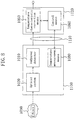
FIG. 8 is a diagram illustrating an exemplary
configuration of a conventional infrared imaging device
(described in Japanese Laid-Open Patent Publication No. 5-302855).
The configuration of FIG. 8 is used for the purpose
of calibrating the relationship between the output signal and
the temperature.
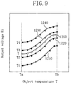
In FIG. 8, the characteristics of an infrared
detector 1010 (object temperature versus brightness table) as
illustrated in FIG. 9 are pre-stored in temperature
characteristic correction means 1050. Each of graph curves
1210, 1220, 1230 and 1240 of FIG. 9 represents a relationship
between an object temperature T and an output voltage Ei of
the infrared detector 1010, with temperatures T1, T2, T3 and
T4 in the vicinity of the infrared detector 1010 being used
as parameters.
Temperature measurement means 1080 measures a
temperature Tx in the vicinity of the infrared detector 1010.
Temperature characteristic correction means 1050 uses the
temperature Tx and the characteristics of FIG. 9 to obtain
the object temperature T from the output voltage Ei of the
infrared detector 1010. Assuming that T2<Tx<T3, the
temperature characteristic correction means 1050 creates a
characteristic curve 1250 by interpolating the graph curves
1220 and 1230, respectively corresponding to the temperatures
T2 and T3, and converts the output voltage Ei of the infrared
detector 1010 into the object temperature T by using the
characteristic curve 1250.
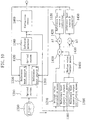
FIG. 10 is a diagram illustrating another exemplary
configuration of a conventional infrared imaging device
(described in Japanese Laid-Open Patent Publication No. 10-111172).
In FIG. 10, optical systems 1310 and 1320 cause the
infrared image of an object 1330 to form an image on an
infrared detector 1340. Each of a reference heat source A
1350 and a reference heat source B 1360 is a heat source
using a Peltier element, and the temperature thereof is
variable and controlled by controllers 1440 and 1450,
respectively.
The infrared imaging device illustrated in FIG. 10
images the target object during an effective scanning period,
while it images the reference heat source A 1350 and the
reference heat source B 1360 during an ineffective scanning
period. Average value calculation means 1370 calculates the
average value of the output of the infrared detector 1340
during the effective scanning period. Reference heat source
A output calculation means 1380 calculates the average value
of the output of the infrared detector 1340 while imaging the
reference heat source A 1350 during the ineffective scanning
period, whereas the reference heat source output calculation
means 1390 calculates the average value of the output of the
infrared detector 1340 while imaging the reference heat
source B 1360 during the ineffective scanning period, and
median value output means 1400 outputs the median value of
these calculation results. A subtractor 1410 subtracts the
output of the median value output means 1400 from the output
of the average value calculation means 1370, and an adder
1420 adds a predetermined temperature difference ÄT to the
subtraction result and provides the obtained value to the
reference heat source A controller 1440, whereas a subtractor
1430 subtracts the temperature difference ÄT from the
subtraction result and provides the obtained value to the
reference heat source B controller 1450. The controllers
1440 and 1450 perform a feedback control so that the
subtraction result of the subtractor 1410 is zero, i.e., the
output of the average value calculation means 1370 and the
output of the median value output means 1400 are equal to
each other.
With such a control, even if the scene being imaged
changes, the temperatures of the reference heat source A 1350
and the reference heat source B 1360 change according to the
average value of the temperature of the obtained image, and
are always controlled within a predetermined temperature
range (average value±Ät). Correction means 1460 obtains a
correction coefficient used for correcting output variations,
based on the output of the infrared detector 1340 while
imaging the reference heat source A 1350 and the reference
heat source B 1360 during the ineffective scanning period.
In this way, a temperature calibration suitable for the
temperature range to be measured is realized.
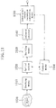
FIG. 11 is a diagram illustrating another exemplary
configuration of a conventional infrared imaging device
(described in Japanese Laid-Open Patent Publication No. 10-142065).
The configuration of FIG. 11 is used for the
purpose of eliminating two-dimensional output variations.
In FIG. 11, first shutting means 1510 is provided for
shading correction, and second shutting means 1530 is
provided for inter-pixel output variation correction. During
an imaging operation, the first and second shutting means
1510 and 1530 are open, whereby an infrared radiation coming
through an optical system 1520 forms an image on an infrared
detector 1540.
The first shutting means 1510 is closed by a control
means 1560 once in every 30 seconds so as to shut off the
infrared radiation. In this state, inter-pixel output
variation correction means 1550 determines a shading
correction value based on the output of the infrared detector
1540. On the other hand, the second shutting means 1530 is
also closed by the control means 1560 once in every 30
seconds so as to shut off the infrared radiation. In this
state, the inter-pixel output variation correction means 1550
determines a sensitivity correction value based on the output
of the infrared detector 1540.
PROBLEMS TO BE SOLVED BY THE INVENTION
In order to obtain, with a good precision, the
temperature information of the object by using an infrared
imaging device, it is necessary to perform two types of image
correction. One is a so-called "temperature calibration",
i.e., a calibration of the relationship between the output
signal (brightness signal) and the temperature, and the other
is a correction of two-dimensional output variations in the
image.
Possible factors necessitating the temperature
calibration include changes in characteristics due to changes
in the temperature of the infrared detector itself,
fluctuations in the amount of infrared radiation from an
optical system such as a lens or a lens barrel due to changes
in temperature, etc. For example, when an infrared imaging
device is used outdoors, there are violent temperature
changes, whereby even immediately after a temperature
calibration, the correspondence between the temperature and
the brightness shifts from the actual values, thereby
reducing the legibility of the image. Moreover, when it
rains, the brightness level substantially decreases for the
same object being imaged due to a temperature decrease.
There are two factors for two-dimensional output
variations. One is sensitivity variations among various
pixels of an infrared detector, and non-uniformities are
introduced to the surface of an infrared image by such
sensitivity variations. The other is what is called "lens
shading", which is a phenomenon wherein the amount of light
received by a central portion of the infrared detector is
uniformly higher than that received by a peripheral portion
thereof, due to the nature of the optical system.
In the conventional example of FIG. 8, the
temperature in the vicinity of the infrared detector 1010 is
measured, and an object temperature versus brightness table
is referenced based on the vicinity temperature. However, in
the case of imaging with an infrared imaging device being
installed outdoors, for example, the temperature of an
optical system 1020 is substantially different from the
temperature in the vicinity of the infrared detector 1010,
whereby the amount of infrared radiation from the optical
system 1020 during an imaging operation is substantially
different from that when the table is created. As a result,
it is not always possible to realize a high precision
temperature compensation.
In the conventional example of FIG. 10, the heat
sources serving as references for the temperature calibration
are provided between the optical systems. Therefore, in the
case of imaging with an infrared imaging device being
installed outdoors, for example, there are violent
fluctuations in the temperature of the optical systems, and
the calibration cannot be performed with the influence of the
fluctuations in the temperature of the optical systems being
taken into consideration. Particularly, the fluctuations in
the infrared radiation from the optical system 1310 on the
outer side with respect to the heat sources are substantial,
thereby fluctuating the apparent measured temperature of the
object.
Moreover, the conventional example of FIG. 11,
despite the complicated configuration with two shutting means,
can only correct two-dimensional output variations, and
cannot calibrate the relationship between the output signal
and the temperature. Moreover, since the timing at which to
perform a correction is fixed, it is not suitable for use as
a surveillance camera, or the like, because there are periods
during which an imaging operation cannot be performed.
As described above, conventional infrared imaging
devices have not necessarily succeeded in realizing a high
precision image correction. Particularly, serious problems
arise when they are used under environments with violent
changes such as when they are installed in a vehicle.
DISCLOSURE OF THE INVENTION
An object of the present invention is to provide an
infrared imaging device with a simple structure capable of
realizing an image correction with a higher precision than in
the prior art.
Specifically, the present invention provides an
infrared imaging device, including: an infrared detector; an
optical system for causing an infrared radiation from an
object to form an image on the infrared detector; shutting
means configured so that the shutting means can be
opened/closed and so as to shut off an infrared radiation
coming into the optical system when the shutting means is
closed; and correction means for correcting an output of the
infrared detector, wherein the correction means determines a
correction coefficient for correcting fluctuations in an
amount of infrared radiation from the optical system by using
an output of the infrared detector imaging the shutting means
while the shutting means is closed.
According to the present invention, the shutting
means is provided for shutting off, when it is closed, the
infrared radiation coming into the optical system, and the
correction coefficient for correcting the fluctuations in the
amount of infrared radiation from the optical system while
the shutting means is closed. Therefore, it is possible to
perform a correction with the fluctuations in the radiation
from the optical system being taken into consideration.
Therefore, it is possible to realize an image correction with
a higher precision than in the prior art.
It is preferred that the correction means in the
infrared imaging device according to the present invention
determines a second correction coefficient for correcting
variations in a DC offset among pixels and fluctuations in an
amount of infrared radiation from the optical system by using
the output of the infrared detector imaging the shutting
means being closed and a first correction coefficient
proportional to a sensitivity of each pixel of the infrared
detector and shading.
It is preferred that the infrared imaging device
includes second shutting means configured so that the second
shutting means can be opened/closed and so as to shut off an
infrared radiation coming into the optical system when the
second shutting means is closed; and the correction means
determines the first correction coefficient by using the
output of the infrared detector imaging the shutting means
being closed and an output of the infrared detector imaging
the second shutting means being closed.
It is preferred that the infrared imaging device
includes temperature setting means for setting a temperature
of the shutting means; and the correction means determines
the first correction coefficient by using an output of the
infrared detector imaging the shutting means being closed,
which has been set to a first temperature by the temperature
setting means, and an output of the infrared detector imaging
the shutting means being closed, which has been set to a
second temperature by the temperature setting means.
It is preferred that the infrared imaging device
according to the present invention includes temperature
measurement means for measuring a surface temperature of the
shutting means; and the correction means determines the
correction coefficient by using a temperature measured by the
temperature measurement means.
It is preferred that the optical system in the
infrared imaging device according to the present invention is
set to a non-focused state while the shutting means is closed.
It is preferred that the shutting means in the
infrared imaging device according to the present invention is
a flat-plate member having a uniform temperature distribution.
It is preferred that the infrared imaging device
according to the present invention includes temperature
setting means for setting a temperature of the shutting
means; and the temperature setting means sets the temperature
of the shutting means to a temperature in a vicinity of a
temperature of a particular object to be imaged while the
shutting means is closed.
The present invention also provides an infrared
imaging device to be installed in a moving object, the
infrared imaging device including: an infrared detector;
correction means for correcting an output of the infrared
detector; and control means for controlling a timing at which
the correction means determines a correction coefficient
based on a signal sent from at least one of the following
means provided in the moving object: means for detecting a
speed of the moving object; means for identifying a traffic
signal of a traffic light located in a traveling direction of
the moving object; and means for determining presence/absence
of an object to be detected in the traveling direction of the
moving object.
According to the present invention, when the infrared
imaging device is installed in a moving object, the timing at
which to determine the correction coefficient is controlled
based on at least one of the following: the speed of the
moving object; the traffic signal of the traffic light
located in the traveling direction of the moving object; and
the presence/absence of an object to be detected in the
traveling direction of the moving object. Therefore, it is
possible to determine the correction coefficient at
appropriate timings.
The present invention also provides a vehicle having
the infrared imaging device according to the present
invention, the vehicle including means for detecting a speed
of the vehicle, wherein the control means provided in the
infrared imaging device receives an output signal of the
speed detection means to control the timing at which to
determine the correction coefficient. Alternatively, the
vehicle includes means for identifying a traffic signal of a
traffic light located in a traveling direction of the vehicle,
wherein the control means provided in the infrared imaging
device receives an output signal of the traffic light
identification means to control the timing at which to
determine the correction coefficient. Alternatively, the
vehicle includes means for determining presence/absence of an
object to be detected in a traveling direction of the vehicle,
wherein the control means provided in the infrared imaging
device receives an output signal of the object determination
means to control the timing at which to determine the
correction coefficient.
The present invention also provides an infrared
imaging device to be installed in a vehicle, the infrared
imaging device including: an infrared detector; an optical
system for causing an infrared radiation from an object to
form an image on the infrared detector; and a temperature
retaining structure for stabilizing a temperature in a
vicinity of the infrared detector and the optical system by
using a mechanism in the vehicle.
According to the present invention, when the infrared
imaging device is installed in a vehicle, the temperature in
the vicinity of the infrared detector and the optical system
is stabilized by the temperature retaining structure using a
mechanism in the vehicle. In this way, fluctuations of the
image quality are suppressed.
It is preferred that the temperature retaining
structure circulates an engine coolant of the vehicle in the
vicinity of the infrared detector and the optical system.
The present invention also provides a vehicle,
including: an infrared imaging device; and a temperature
retaining structure for stabilizing a temperature in a
vicinity of the infrared imaging device by using a mechanism
in the vehicle.
It is preferred that the temperature retaining
structure circulates an engine coolant of the vehicle in the
vicinity of the infrared imaging device.
The present invention also provides an infrared
imaging device to be installed in a vehicle, the infrared
imaging device including a mechanism for setting/changing a
imaging direction of the infrared imaging device, wherein the
mechanism sets the imaging direction toward outside of the
vehicle during a normal operation, and sets the imaging
direction toward a part of the vehicle, which is to be a
temperature reference, during a calibration operation.
The present invention also provides a vehicle,
including: an infrared imaging device; and a mechanism for
setting/changing a imaging direction of the infrared imaging
device, wherein the mechanism sets the imaging direction
toward outside of the vehicle during a normal operation, and
sets the imaging direction toward a part of the vehicle,
which is to be a temperature reference, during a calibration
operation.
With such configurations of the present invention, an
infrared imaging device installed in a vehicle can calibrate
temperature characteristics without providing a special
temperature reference.
The present invention also provides an infrared image
adjustment device for adjusting a display temperature range
of an infrared image, including: first means for detecting,
from the infrared image, an upper limit and a lower limit of
a temperature range suitable for displaying the infrared
image; second means for storing a predetermined temperature
based on a particular object to be imaged; and third means
for setting the display temperature range so as to include at
least the predetermined temperature, based on the upper and
lower limit temperatures detected by the first means and the
predetermined temperature stored in the second means.
According to the present invention, since the
predetermined temperature based on the particular object to
be imaged is included in the display temperature range, the
display brightness of the infrared image does not fluctuate
even in cases where the object to be imaged appears and
disappears in the obtained image. Therefore, it is possible
to display a stable image, whereby a detailed classification
operation, or the like, using an infrared image pattern can
be realized.
In the infrared imaging device according to the
present invention, the second means stores, as the
predetermined temperature, an upper limit and a lower limit
of a temperature range based on the particular object to be
imaged; and the third means sets, as an upper limit of the
display temperature range, a larger one of the upper limit
temperature detected by the first means and the upper limit
temperature stored in the second means, while setting, as a
lower limit of the display temperature range, a smaller one
of the lower limit temperature detected by the first means
and the lower limit temperature stored in the second means.
The first means in the infrared imaging device
according to the present invention detects a highest
temperature and a lowest temperature among temperatures
indicated by the infrared image as an upper limit and a lower
limit, respectively, of the temperature range.
BRIEF DESCRIPTION OF THE DRAWINGS
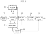
FIG. 1 is a block diagram illustrating a
configuration of an infrared imaging device according to the
first embodiment of the present invention.
FIG. 2 is a diagram showing a model for illustrating
a calibration method according to the first embodiment of the
present invention.
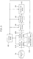
FIG. 3 is a diagram illustrating an alternative
example of the configuration of FIG. 1.
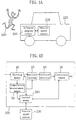
FIG. 4 is a diagram illustrating a configuration of a
vehicle having an infrared imaging device according to the
second embodiment of the present invention installed therein.
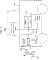
FIG. 5 is a diagram illustrating a configuration of a
vehicle having an infrared imaging device according to the
third embodiment of the present invention installed therein.
FIG. 6 is a diagram illustrating a configuration of a
vehicle having an infrared imaging device according to the
fourth embodiment of the present invention installed therein.
FIG. 7 is a diagram illustrating a configuration of a
vehicle having an infrared imaging device according to the
fifth embodiment of the present invention installed therein.
FIG. 8 is a diagram illustrating a configuration of a
conventional infrared imaging device.
FIG. 9 is a diagram illustrating an object
temperature versus brightness table of a temperature
characteristic correction means of FIG. 8.
FIG. 10 is a configuration of a conventional infrared
imaging device.
FIG. 11 is a configuration of a conventional infrared
imaging device.
BEST MODE FOR CARRYING OUT THE INVENTION
(FIRST EMBODIMENT)
FIG. 1 is a block diagram illustrating a
configuration of an infrared imaging device according to the
first embodiment of the present invention. In FIG. 1, 10 is
an infrared detector such as a microbolometer for detecting
an infrared radiation, 20 is an optical system having a lens
for causing an infrared radiation from an object 70 to form
an image on the infrared detector 10, and 30 is correction
means 30 for correcting the output of the infrared detector
10. Shutting means 40 is configured so that it can be
opened/closed and so as to shut off the infrared radiation
coming from the object 70 into the optical system 20 when it
is closed. Temperature measurement means 50 measures the
surface temperature of the shutting means 40. Control means
60 controls the open/closed state of the shutting means 40,
and also controls the optical system 20, the correction means
30 and the temperature measurement means 50.
Herein, it is assumed that the infrared detector 10
is a two-dimensional area sensor having pixels in a two-dimensional
arrangement. Temperature setting means 52 will
be described later.
The operation of the infrared imaging device having
such a configuration will now be described.
First, while imaging the object 70, the shutting
means 40 is closed by a control of the control means 60.
Therefore, an infrared radiation from the object 70 is caused
by the optical system 20 to form an image as an infrared
image on the infrared detector 10. The infrared detector 10
outputs a signal according to the amount of light received by
each pixel. The output of the infrared detector 10 is
corrected by the correction means 30. The correction means
30 corrects the sensitivity variations among pixels, the DC
offset variations among pixels, the shading effect of the
lens, and the influence of the infrared radiation from the
optical system 20.
Next, the correction method of the correction means
30 will be described.
FIG.
2 is a diagram showing a model for illustrating
a calibration method according to the present embodiment. In
the model of FIG.
2, the following values are defined for the
pixel coordinates (x,y) of the
infrared detector 10.
Herein, in the model of FIG.
2, the following expression
holds:
e(x,y,T0)
=a(x,y) · (S(x,y) · L0(x,y,T0)+L1(x,y,T1))+b(x,y)
1) Determination of first correction coefficient
Flat objects 70 having a uniform distribution at
temperatures Ta and Tb, respectively, are imaged so as to
obtain the difference in the output of the infrared detector
10 therebetween.
e(x,y,Ta)-e(x,y,Tb)
=a(x,y)·S(x,y)·(L0(x,y,Ta)-L0(x,y,Tb))
Within a narrow ordinary temperature range (e.g., 0°C to
60°C), the infrared radiation L0 can be approximated by a
linear function of the temperature T0 as in the following
expression:
L0(x,y,T0)=c·T0+d
Herein, c and d are constants. Substitute Expression (3)
into Expression (2) and divide each side by the temperature
difference (Ta-Tb) to obtain a first correction coefficient
G(x,y). Thus,
G(x,y)=(e(x,y,Ta)-e(x,y,Tb))/(Ta-Tb)
=a(x,y)·S(x,y)·c
Then, the obtained first correction coefficient G(x,y) is
stored in the correction means 30.
As can be seen from Expression (4), the first
correction coefficient G(x,y) is proportional to the
sensitivity (gain) of each pixel and the lens shading. By
using the first correction coefficient G(x,y), it is possible
to correct the influence of the lens shading effect and the
sensitivity variations among pixels.
Note that the sensitivity variations among pixels are
caused primarily by variations in the processing dimension
among pixels during the manufacture process, and do not
substantially change after the device is manufactured.
Therefore, the determination of the first correction
coefficient G(x,y) does not need to be performed periodically
during use of the device, and needs to be performed only once
when the device is manufactured particularly in cases where
the optical system 20 of a fixed focus type is used.
2) Determination of second correction coefficient
At start-up of the infrared imaging device, or after
a long-time imaging operation, image non-uniformities or
fluctuations in the average brightness level occur because of
the temperature variations of the optical system 20 and/or
slight output variations among pixels of the infrared
detector 10 due to temperature fluctuations. When such
phenomena occur, the control means 60 is manually activated
so as to determine a second correction coefficient for
correcting the output variations among pixels.
First, the shutting means 40 is closed from the open
state by a control signal from the control means 60, thereby
shutting off the infrared radiation coming into the optical
system 20. Then, an average temperature Tc of the shutting
means 40 is measured by the temperature measurement means 50.
At this time, the optical system 20 is preferably set to a
non-focused state. Moreover, it is preferred that the
shutting means 40 is a flat-plate member having a uniform
temperature distribution. When the focal point of the
optical system 20 is at a distance of a few meters or more,
the shutting means 40, which is placed immediately before the
optical system 20, forms an image on the infrared detector 10
in a defocused state. Herein, the second correction
coefficient H(x,y) expressed as
H(x,y)=K-e(x,y,Tc)/G(x,y)
is obtained, and stored in the correction means 30. K is a
constant. Thus, the second correction coefficient H(x,y) is
obtained so that the outputs from all pixels are uniform when
imaging the shutting means 40 at the temperature Tc.
The second correction coefficient H(x,y) is a
correction coefficient for correcting DC offset variations
among pixels and fluctuations in the amount of infrared
radiation from the optical system 20 (DC component
variations). Now, by dividing both sides of Expression (1)
by both sides of the Expression (4), respectively, it is
possible to eliminate the influence of the lens shading and
the sensitivity variations among pixels. What remains there
is only the influence of DC component variations.
e(x,y,T0)/G(x,y)
=L0(x,y,T0)/c
+L1(x,y,T1)/c·S(x,y)+b(x,y)/G(x,y)
In Expression (6), the first term of the right side
represents the radiation of the object 70, and the second
term and the third term represent the DC component, which
varies among pixels. Of the terms representing the DC
component, what is varied by environmental fluctuations is
the term of the radiation L1 of the optical system 20. This
term varies according to the temperature T1 of the optical
system 20. Therefore, it is desirable that the second
correction coefficient H(x,y) is updated each time the
temperature T1 of the optical system 20 changes.
3) Correction of imaging signal
During an imaging operation, imaging signals are
corrected as follows. The control means 60 opens the
shutting means 40, and starts imaging the object 70. At this
time, the correction output signal E(x,y,T0) is obtained as
in the following expression:
E(x,y,T0)
=e(x,y,T0)/G(x,y)+H(x,y)
At this time,
dE/dT0=c2
Thus, the correction output E increases by c2 for each 1-degree
increase in the temperature of the object 70. Since
E=K when T0=Tc,
E(x,y,T0)
=c2·(T0-Tc)+K
Rearranging the expression with respect to T0 gives
T0=(E(x,y,T0)-K)/c2+Tc
Herein, c2 is a constant that is not fluctuated by the
environment.
The correction output signal E(x,y,T0) ensures that
Expression (10) holds as long as the temperature of the
optical system 20 is constant both upon determination of the
second correction coefficient H(x,y) and upon imaging of the
object while the infrared radiation from the object 70 does
not fluctuate. Thus, the correction output signal E(x,y,T0)
is a signal representing the two-dimensional temperature
distribution of the object 70 with the output variations
among pixels being corrected. The correction means 30
converts the correction output signal E(x,y,T0) into a video
image signal of a dynamic range suitable for display, and
outputs the video image signal.
Thereafter, if the temperature of the optical system
20 changes due to external temperature fluctuations or heat
radiation of the internal electric circuits, etc., thereby
causing non-uniformities to be introduced into the image
and/or increasing the difference between the actual
temperature and the temperature calculated from the imaging
signal, the control means 60 may be activated to update the
second correction coefficient H(x,y) again. Therefore, it is
desirable to start imaging the object before the temperature
of the optical system 20 substantially changes after updating
the second correction coefficient H(x,y).
Moreover, the temperature setting means 52 for
setting the temperature of the shutting means 40 may be
provided. The temperature setting means 52 can be easily
implemented by, for example, a combination of a heater and a
temperature sensor. By using the temperature setting means
52, it is possible to set the temperature Tc of the shutting
means 40 to a desired value when obtaining the second
correction coefficient H(x,y). The temperature Tc of the
shutting means 40 at this time is preferably set to a
temperature in the vicinity of the temperature of the
particular object to be imaged (e.g., a "human").
Moreover, the shutting means 40 may be used also when
setting the first correction coefficient G(x,y). In such a
case, the shutting means 40 can be imaged while being closed
and set to the first temperature Ta using the temperature
setting means 52, and then imaged while being closed and set
to the second temperature Tb.
FIG. 3 is a diagram illustrating an alternative
example of the infrared imaging device according to the first
embodiment of the present invention. In the configuration of
FIG. 3, two shutting means 110 and 120 are provided as means
for shutting off an infrared radiation coming into the
optical system 20. The temperature measurement means 130 is
configured so that it can measure the temperature of each of
the first and second shutting means 110 and 120.
With the configuration of FIG. 3, the first and
second shutting means 110 and 120 can be used for setting the
first correction coefficient G(x,y). Specifically, first,
the output of the infrared detector 10 while imaging the
first shutting means 110 having the uniform first temperature
Ta, with the second shutting means 120 being open and the
first shutting means 110 being closed, is stored. Then, the
output of the infrared detector 10 while imaging the second
shutting means 120 having the uniform second temperature Tb,
with the first shutting means 110 being open and the second
shutting means 120 being closed, is stored. Then, the first
correction coefficient G(x,y) can be obtained by a method as
described above using the stored output signals.
Note that the temperature calibration may be
performed using the shutting means 40 by another method other
than the calibration method described above in the present
embodiment. By using the shutting means 40 for shutting off
the infrared radiation coming into the optical system 20, it
is possible to realize a correction with the influence of the
radiation of the optical system 20 being taken into
consideration.
Alternatively, the temperature measurement means 50
may not be provided. When the temperature measurement means
50 is not provided, the temperature Tc of the shutting means
40 when obtaining the second correction coefficient H(x,y) is
unknown, whereby the temperature T0 of the object 70 cannot
be obtained by using Expression (9). However, the relative
temperature versus brightness characteristics can be obtained
more accurately than in the prior art. Specifically, in
Expression (6), the characteristics variations among pixels
due to shading of the optical system 20 are corrected by the
first term of the right side, and the fluctuations in the
radiation from the optical system 20 are corrected by the
second term of the right side. In this way, the effect of
shading and the fluctuations in the radiation from the
optical system 20 can be corrected individually, whereby it
is possible to obtain more accurate relative temperature
versus brightness characteristics.
(SECOND EMBODIMENT)
FIG. 4 is a diagram illustrating a general
configuration of a vehicle having an infrared imaging device
according to the second embodiment of the present invention
installed therein. In FIG. 4, those elements that are also
shown in FIG. 1 are provided with the same reference numerals
as in FIG. 1. As illustrated in FIG. 4(b), an infrared
imaging device 200 illustrated in FIG. 4(a) installed in a
vehicle 220, as a moving object, has substantially the same
configuration as that of the first embodiment. The infrared
imaging device 200 is installed for imaging on the front side
of the vehicle 220 with respect to the traveling direction
thereof in order to detect an object 240 (a human or another
vehicle) on the front side with respect to the traveling
direction. An output signal of a vehicle speed sensor 230,
as means for detecting the speed of the vehicle 220, is
provided to control means 210 of the infrared imaging device
200.
When the infrared imaging device 200 is installed in
the vehicle 220, it is subject to the influence of the
weather, the temperature, the traveling speed, etc., whereby
the temperature of the optical system 20 thereof fluctuates
easily. Therefore, the second correction coefficient H(x,y)
illustrated in the first embodiment needs to be updated
frequently. Since a normal imaging operation cannot be
performed while updating the correction coefficient, it is
not preferable to update the correction coefficient
frequently while the vehicle 220 is running.
In view of this, the present embodiment uses the
output signal of the vehicle speed sensor 230 so that the
correction coefficient is updated during a period in which
the vehicle 220 is at a stop or during a period in which the
vehicle 220 is running at a very low speed. In this way, the
calibration is performed only when there is substantially no
possibility of hitting an obstacle, thereby realizing a
temperature calibration without losing the meaning of
providing the infrared imaging device.
Specifically, the calibration is performed as in the
first embodiment. That is, the first correction coefficient
G(x,y) is obtained in advance when the infrared imaging
device 200 is manufactured. Then, when it is detected from
the output signal of the vehicle speed sensor 230 that the
vehicle 220 has come to a stop or the speed thereof has
become less than or equal to a predetermined value, the
shutting means 40 is closed and the second correction
coefficient H(x,y) is updated.
Note that also with other correction methods, it is
preferred that the timing at which to perform the calibration
is controlled by using the output signal of the vehicle speed
sensor 230 as in the present embodiment. Moreover, the
device can be used with a moving object other than a vehicle,
e.g., a train, a ship, an airplane, etc.
(THIRD EMBODIMENT)
FIG. 5 is a diagram illustrating a general
configuration of a vehicle having an infrared imaging device
according to the third embodiment of the present invention
installed therein. In FIG. 5, those elements that are also
shown in FIG. 4 are provided with the same reference numerals
as in FIG. 4. The infrared imaging device 200 employs a
configuration of FIG. 4(b).
In FIG. 5, the infrared imaging device 200 installed
in the vehicle 220 receives, at the control means 210, an
output signal of means 310 for identifying the traffic signal
of a traffic light located in the traveling direction and an
output signal of means 340 for determining the
presence/absence of a human, as a detection object, in the
traveling direction, in addition to the output signal of the
vehicle speed sensor 230. The traffic light identification
means 310 detects the position of a traffic light from the
camera image and determines the color of the light that is
turned ON. Moreover, the human detection/determination means
340 extracts an image of a predetermined temperature range
from the infrared image, and determines the presence/absence
of a human based on the size, the shape, etc., of the image.
In the present embodiment, the traffic light
identification means 310 or the human detection/determination
means 340 are used, in addition to the vehicle speed sensor
230, for controlling the calibration timing. In this way, it
is possible to reliably ensure activation of the infrared
imaging device 200 when the operation thereof is needed. For
example, the infrared imaging device 200 is designed so that
it updates the correction coefficient only when the vehicle
speed sensor 230 detects that the traveling speed of the
vehicle 220 is zero, the traffic light identification means
310 identifies that the traffic signal of the traffic light
in front of the vehicle 220 indicates "STOP" to the vehicle
220, and the human detection/determination means 340 is not
detecting a human. In this way, it is possible to perform a
calibration only when there is substantially no possibility
of hitting an obstacle in an even more reliable manner than
in the second embodiment.
Moreover, in the infrared imaging device 200, a
peripheral structure 320 thereof is filled with a circulating
engine coolant provided from a radiator 330 of the vehicle
220. Since the temperature of a coolant is substantially
constant after the vehicle 220 has been warmed up, the
temperature of the infrared imaging device 200 in operation
is stabilized by the peripheral structure 320, as a
temperature retaining structure. This reduces the
temperature fluctuations of the optical system and reduces
the fluctuations in the image quality.
Note that any one or two of the vehicle sensor 230,
the traffic light identification means 310 and the human
detection means 340 may be used for controlling the
calibration timing, or another sensor may be used in addition.
Moreover, the peripheral structure 320 may be either
provided integrally with the infrared imaging device 200 or
provided on the vehicle 220 side so that the infrared imaging
device 200 is fitted therein. Moreover, another mechanism of
the vehicle 220 may be used to realize the temperature
retaining structure.
(FOURTH EMBODIMENT)
FIG. 6 is a diagram illustrating a configuration of a
vehicle having an infrared imaging device according to the
fourth embodiment of the present invention installed therein.
In FIG. 6, those elements that are also shown in FIG. 1 and
FIG. 4 are provided with the same reference numerals as in
FIG. 1 and FIG. 4. In FIG. 6, 410 and 420 are mirrors for
reflecting an infrared radiation of wavelengths used for
imaging, 430 is a mirror driving device for controlling the
direction of the mirror 420, 440 is a radiator of the vehicle
220, and 450 is temperature measurement means for measuring
the temperature of the radiator 440. The angle and position
of the mirror 410 are fixed. Moreover, in the configuration
of FIG. 6, shutting means is not provided.
The infrared imaging device illustrated in FIG. 6
performs a calibration when the speed of the vehicle 220
detected by the vehicle speed sensor 230 is less than or
equal to a predetermined value, as in the second embodiment.
In the present embodiment, the radiator 440 is imaged as a
temperature reference during a calibration.
During a calibration, the mirror driving device 430
sets the direction of the mirror 420 so that an infrared
radiation coming from outside the vehicle 220 into the
optical system 20 is shut off while an infrared radiation
radiated from the radiator 440 and reflected by the mirror
410 is allowed to come into the optical system 20. In this
state, a calibration as that of the first embodiment, for
example, is performed. Since the temperature of the radiator
440 is kept substantially constant while the vehicle 220 is
running, the radiator 440 can be used as a temperature
reference in a calibration.
On the other hand, during a normal imaging operation,
the mirror driving device 430 sets the direction of the
mirror 420 so that an infrared radiation radiated from the
radiator 440 and reflected by the mirror 410 is shut off
while an infrared radiation coming from outside the vehicle
220 is allowed to come into the optical system 20.
As described above, according to the present
embodiment, an infrared imaging device installed in a vehicle
can calibrate temperature characteristics without providing a
special temperature reference such as the shutting means
provided in the first embodiment.
Note that while the radiator 440 is used as a
temperature reference in the present embodiment, any other
part of the vehicle whose temperature is constant may be used
as a temperature reference.
Moreover, in the present embodiment, a mechanism for
setting/changing the imaging direction is implemented by the
mirror 420 and the mirror driving device 430. Alternatively,
any other mechanism, e.g., a mechanism for changing the
direction of the imaging device itself, including the
infrared detector 10 and the optical system 20, may be used.
Moreover, the mechanism for setting/changing the imaging
direction may be either provided integrally with the infrared
imaging device or provided on the vehicle side.
(FIFTH EMBODIMENT)
FIG. 7 is a diagram illustrating a configuration of
an infrared image adjustment device according to the fifth
embodiment of the present invention. In FIG. 7, an infrared
imaging device 500 has a configuration as illustrated in FIG.
1, and it is assumed that the first correction coefficient
G(x,y) and the second correction coefficient H(x,y) have
already been obtained according to the procedure illustrated
in the first embodiment. Thus, the correspondence between
the brightness signal output from the infrared imaging device
500 and the temperature of the object is known.
An infrared image adjustment device 590 adjusts the
display temperature range of an infrared image. In the
infrared image adjustment device 590, 510 is an image memory
for storing infrared image data, 520 is a highest temperature
detection section for detecting a highest temperature Th from
the infrared image data stored in the image memory 510, and
530 is a lowest temperature detection section for detecting a
lowest temperature Tl from the infrared image data stored in
the image memory 510. 540 is a memory storing an upper limit
Toh and a lower limit Tol of the measured temperature range
based on the temperature of a particular object to be imaged,
550 is a first comparison section for comparing the highest
temperature Th with the upper limit Toh of the temperature
range so as to selectively output the larger value, and 560
is a second comparison section for comparing the lowest
temperature T1 with the lower limit Tol of the temperature
range so as to selectively output the smaller value.
The image memory 510, the highest temperature
detection section 520 and the lowest temperature detection
section 530 together form first means, the temperature range
upper/lower limit memory 540 forms second means, and the
first and second comparison sections 550 and 560 together
form third means. The infrared image adjustment device 590
outputs the selective outputs of the first and second
comparison sections 550 and 560 as an upper limit temperature
Tah and a lower limit temperature Tal, respectively, of the
display temperature range.
The video image signal generation section 570
receives the output of the infrared imaging device 500 and
generates a video image signal used for displaying an
infrared image on a video image display device 580. At this
time, the dynamic range of the video image signal is adjusted
by using the upper limit temperature Tah and the lower limit
temperature Tal output from the infrared image adjustment
device 590 so that the upper limit temperature Tah matches
the white level and the lower limit temperature Tal matches
the black level.
Now, it is assumed that an imaging operation is
performed by using the infrared imaging device 500 in order
to detect a "human" outdoors in winter. In this case, for
example, the upper limit Toh and the lower limit Tol of the
measured temperature range are set to 35°C and 30°C,
respectively.
When a control circuit 600 activates the infrared
image adjustment device 590, one frame of image data output
from the infrared imaging device 500 is stored in the image
memory 510. The highest temperature detection section 520
detects the temperature Th indicated by the highest
brightness pixel in the object frame image, and the lowest
temperature detection section 530 detects the temperature Tl
indicated by the lowest brightness pixel in the object frame
image.
When outdoors in winter, the temperature of a
building, the asphalt on a road, etc., is lower than the
surface temperature of a human. Thus, the following
relationship:
Tl<Th<Tol<Toh
holds. Therefore, the first comparison section 550 outputs,
instead of the highest temperature Th detected by the highest
temperature detection section 520, the upper limit
temperature Toh stored in the temperature range upper/lower
limit memory 540 as the upper limit temperature Tah of the
display temperature range, while the second comparison
section 560 outputs the lowest temperature T1 detected by the
lowest temperature detection section 530 as the lower limit
temperature Tal of the display temperature range.
In this way, the temperature range of a human, which
is the object to be imaged, is always included in the dynamic
range of the video image signal. Therefore, even in cases
where a human appears and disappears in the obtained image,
the dynamic range of the video image signal does not
fluctuate, and abrupt fluctuations in the brightness of a
video image as those that occur due to AGC (Auto Gain
Control) do not occur. Thus, a detailed classification
operation, or the like, using pattern recognition, for
example, can be easily realized.
Similarly, when detecting a "human" outdoors during
the daytime in summer, the following relationship:
Tol<Toh<Tl<Th
usually holds. Therefore, the first comparison section 550
outputs the highest temperature Th detected by the highest
temperature detection section 520 as the upper limit
temperature Tah of the display temperature range, while the
second comparison section 560 outputs, instead of the lowest
temperature T1 detected by the lowest temperature detection
section 530, the lower limit Tol stored in the temperature
range upper/lower limit memory 540 as the lower limit
temperature Tal of the display temperature range. In this
way, the temperature range of a human, which is the object to
be imaged, is always included in the dynamic range of the
video image signal, and abrupt fluctuations in the brightness
of a video image do not occur.
In cases where the dynamic range of the image becomes
insufficient or the image is saturated due to fluctuations in
the temperature of the background being imaged, the video
image signal adjustment device 590 may be activated again by
the control circuit 600 so as to re-set the display
temperature range. Alternatively, the setting of the display
temperature range may be performed for each frame image as in
the case of AGC.
As described above, according to the present
embodiment, a predetermined temperature range based on the
temperature of a particular object to be imaged is included,
in advance, in the display temperature range, whereby it is
possible to display a stable infrared image even when an
object to be imaged suddenly comes into the imaging range.
Note that the infrared image adjustment device 590 of
the present embodiment may be either provided integrally with
infrared imaging device 500 or provided integrally with the
video image signal generation section 570 and the video image
display device 580.
Moreover, in the present embodiment, the highest
temperature and the lowest temperature of an infrared image
are detected first. Alternatively, the upper limit and the
lower limit of a temperature range suitable for displaying an
infrared image may be detected. For example, a pixel having
a brightness that is substantially different from other
pixels may be excluded from the temperature detection.
Moreover, instead of setting a measured temperature
range, a single predetermined temperature may be set so that
the predetermined temperature is included in the display
temperature range. In the present embodiment, this can be
achieved easily by a setting such that Toh=Tol.