EP1160480A2 - Caliper and a method for assembly of a brake mechanism in said caliper - Google Patents
Caliper and a method for assembly of a brake mechanism in said caliper Download PDFInfo
- Publication number
- EP1160480A2 EP1160480A2 EP01112018A EP01112018A EP1160480A2 EP 1160480 A2 EP1160480 A2 EP 1160480A2 EP 01112018 A EP01112018 A EP 01112018A EP 01112018 A EP01112018 A EP 01112018A EP 1160480 A2 EP1160480 A2 EP 1160480A2
- Authority
- EP
- European Patent Office
- Prior art keywords
- caliper
- brake
- brake mechanism
- bearing bracket
- opening
- Prior art date
- Legal status (The legal status is an assumption and is not a legal conclusion. Google has not performed a legal analysis and makes no representation as to the accuracy of the status listed.)
- Withdrawn
Links
- 230000007246 mechanism Effects 0.000 title claims abstract description 68
- 238000000034 method Methods 0.000 title claims abstract description 12
- 238000007789 sealing Methods 0.000 claims description 11
- 238000003754 machining Methods 0.000 description 10
- 230000014509 gene expression Effects 0.000 description 1
- 238000004519 manufacturing process Methods 0.000 description 1
- 238000003801 milling Methods 0.000 description 1
Images


Classifications
-
- F—MECHANICAL ENGINEERING; LIGHTING; HEATING; WEAPONS; BLASTING
- F16—ENGINEERING ELEMENTS AND UNITS; GENERAL MEASURES FOR PRODUCING AND MAINTAINING EFFECTIVE FUNCTIONING OF MACHINES OR INSTALLATIONS; THERMAL INSULATION IN GENERAL
- F16D—COUPLINGS FOR TRANSMITTING ROTATION; CLUTCHES; BRAKES
- F16D65/00—Parts or details
- F16D65/38—Slack adjusters
- F16D65/40—Slack adjusters mechanical
- F16D65/52—Slack adjusters mechanical self-acting in one direction for adjusting excessive play
- F16D65/56—Slack adjusters mechanical self-acting in one direction for adjusting excessive play with screw-thread and nut
- F16D65/567—Slack adjusters mechanical self-acting in one direction for adjusting excessive play with screw-thread and nut for mounting on a disc brake
- F16D65/568—Slack adjusters mechanical self-acting in one direction for adjusting excessive play with screw-thread and nut for mounting on a disc brake for synchronous adjustment of actuators arranged in parallel
-
- F—MECHANICAL ENGINEERING; LIGHTING; HEATING; WEAPONS; BLASTING
- F16—ENGINEERING ELEMENTS AND UNITS; GENERAL MEASURES FOR PRODUCING AND MAINTAINING EFFECTIVE FUNCTIONING OF MACHINES OR INSTALLATIONS; THERMAL INSULATION IN GENERAL
- F16D—COUPLINGS FOR TRANSMITTING ROTATION; CLUTCHES; BRAKES
- F16D65/00—Parts or details
- F16D65/14—Actuating mechanisms for brakes; Means for initiating operation at a predetermined position
- F16D65/16—Actuating mechanisms for brakes; Means for initiating operation at a predetermined position arranged in or on the brake
- F16D65/18—Actuating mechanisms for brakes; Means for initiating operation at a predetermined position arranged in or on the brake adapted for drawing members together, e.g. for disc brakes
-
- B—PERFORMING OPERATIONS; TRANSPORTING
- B23—MACHINE TOOLS; METAL-WORKING NOT OTHERWISE PROVIDED FOR
- B23C—MILLING
- B23C3/00—Milling particular work; Special milling operations; Machines therefor
-
- F—MECHANICAL ENGINEERING; LIGHTING; HEATING; WEAPONS; BLASTING
- F16—ENGINEERING ELEMENTS AND UNITS; GENERAL MEASURES FOR PRODUCING AND MAINTAINING EFFECTIVE FUNCTIONING OF MACHINES OR INSTALLATIONS; THERMAL INSULATION IN GENERAL
- F16D—COUPLINGS FOR TRANSMITTING ROTATION; CLUTCHES; BRAKES
- F16D65/00—Parts or details
- F16D65/14—Actuating mechanisms for brakes; Means for initiating operation at a predetermined position
- F16D65/16—Actuating mechanisms for brakes; Means for initiating operation at a predetermined position arranged in or on the brake
- F16D65/18—Actuating mechanisms for brakes; Means for initiating operation at a predetermined position arranged in or on the brake adapted for drawing members together, e.g. for disc brakes
- F16D65/183—Actuating mechanisms for brakes; Means for initiating operation at a predetermined position arranged in or on the brake adapted for drawing members together, e.g. for disc brakes with force-transmitting members arranged side by side acting on a spot type force-applying member
-
- B—PERFORMING OPERATIONS; TRANSPORTING
- B23—MACHINE TOOLS; METAL-WORKING NOT OTHERWISE PROVIDED FOR
- B23C—MILLING
- B23C2215/00—Details of workpieces
- B23C2215/08—Automotive parts
-
- B—PERFORMING OPERATIONS; TRANSPORTING
- B23—MACHINE TOOLS; METAL-WORKING NOT OTHERWISE PROVIDED FOR
- B23C—MILLING
- B23C2270/00—Details of milling machines, milling processes or milling tools not otherwise provided for
- B23C2270/18—Milling internal areas of components
-
- F—MECHANICAL ENGINEERING; LIGHTING; HEATING; WEAPONS; BLASTING
- F16—ENGINEERING ELEMENTS AND UNITS; GENERAL MEASURES FOR PRODUCING AND MAINTAINING EFFECTIVE FUNCTIONING OF MACHINES OR INSTALLATIONS; THERMAL INSULATION IN GENERAL
- F16D—COUPLINGS FOR TRANSMITTING ROTATION; CLUTCHES; BRAKES
- F16D55/00—Brakes with substantially-radial braking surfaces pressed together in axial direction, e.g. disc brakes
- F16D2055/0004—Parts or details of disc brakes
- F16D2055/0016—Brake calipers
-
- F—MECHANICAL ENGINEERING; LIGHTING; HEATING; WEAPONS; BLASTING
- F16—ENGINEERING ELEMENTS AND UNITS; GENERAL MEASURES FOR PRODUCING AND MAINTAINING EFFECTIVE FUNCTIONING OF MACHINES OR INSTALLATIONS; THERMAL INSULATION IN GENERAL
- F16D—COUPLINGS FOR TRANSMITTING ROTATION; CLUTCHES; BRAKES
- F16D55/00—Brakes with substantially-radial braking surfaces pressed together in axial direction, e.g. disc brakes
- F16D2055/0004—Parts or details of disc brakes
- F16D2055/0037—Protective covers
-
- F—MECHANICAL ENGINEERING; LIGHTING; HEATING; WEAPONS; BLASTING
- F16—ENGINEERING ELEMENTS AND UNITS; GENERAL MEASURES FOR PRODUCING AND MAINTAINING EFFECTIVE FUNCTIONING OF MACHINES OR INSTALLATIONS; THERMAL INSULATION IN GENERAL
- F16D—COUPLINGS FOR TRANSMITTING ROTATION; CLUTCHES; BRAKES
- F16D2121/00—Type of actuator operation force
- F16D2121/14—Mechanical
-
- F—MECHANICAL ENGINEERING; LIGHTING; HEATING; WEAPONS; BLASTING
- F16—ENGINEERING ELEMENTS AND UNITS; GENERAL MEASURES FOR PRODUCING AND MAINTAINING EFFECTIVE FUNCTIONING OF MACHINES OR INSTALLATIONS; THERMAL INSULATION IN GENERAL
- F16D—COUPLINGS FOR TRANSMITTING ROTATION; CLUTCHES; BRAKES
- F16D2125/00—Components of actuators
- F16D2125/18—Mechanical mechanisms
- F16D2125/20—Mechanical mechanisms converting rotation to linear movement or vice versa
- F16D2125/22—Mechanical mechanisms converting rotation to linear movement or vice versa acting transversely to the axis of rotation
- F16D2125/26—Cranks
-
- F—MECHANICAL ENGINEERING; LIGHTING; HEATING; WEAPONS; BLASTING
- F16—ENGINEERING ELEMENTS AND UNITS; GENERAL MEASURES FOR PRODUCING AND MAINTAINING EFFECTIVE FUNCTIONING OF MACHINES OR INSTALLATIONS; THERMAL INSULATION IN GENERAL
- F16D—COUPLINGS FOR TRANSMITTING ROTATION; CLUTCHES; BRAKES
- F16D2125/00—Components of actuators
- F16D2125/18—Mechanical mechanisms
- F16D2125/58—Mechanical mechanisms transmitting linear movement
- F16D2125/64—Levers
-
- F—MECHANICAL ENGINEERING; LIGHTING; HEATING; WEAPONS; BLASTING
- F16—ENGINEERING ELEMENTS AND UNITS; GENERAL MEASURES FOR PRODUCING AND MAINTAINING EFFECTIVE FUNCTIONING OF MACHINES OR INSTALLATIONS; THERMAL INSULATION IN GENERAL
- F16D—COUPLINGS FOR TRANSMITTING ROTATION; CLUTCHES; BRAKES
- F16D2125/00—Components of actuators
- F16D2125/18—Mechanical mechanisms
- F16D2125/58—Mechanical mechanisms transmitting linear movement
- F16D2125/68—Lever-link mechanisms, e.g. toggles with change of force ratio
-
- F—MECHANICAL ENGINEERING; LIGHTING; HEATING; WEAPONS; BLASTING
- F16—ENGINEERING ELEMENTS AND UNITS; GENERAL MEASURES FOR PRODUCING AND MAINTAINING EFFECTIVE FUNCTIONING OF MACHINES OR INSTALLATIONS; THERMAL INSULATION IN GENERAL
- F16D—COUPLINGS FOR TRANSMITTING ROTATION; CLUTCHES; BRAKES
- F16D2250/00—Manufacturing; Assembly
- F16D2250/0084—Assembly or disassembly
-
- Y—GENERAL TAGGING OF NEW TECHNOLOGICAL DEVELOPMENTS; GENERAL TAGGING OF CROSS-SECTIONAL TECHNOLOGIES SPANNING OVER SEVERAL SECTIONS OF THE IPC; TECHNICAL SUBJECTS COVERED BY FORMER USPC CROSS-REFERENCE ART COLLECTIONS [XRACs] AND DIGESTS
- Y10—TECHNICAL SUBJECTS COVERED BY FORMER USPC
- Y10T—TECHNICAL SUBJECTS COVERED BY FORMER US CLASSIFICATION
- Y10T29/00—Metal working
- Y10T29/49—Method of mechanical manufacture
- Y10T29/49826—Assembling or joining
-
- Y—GENERAL TAGGING OF NEW TECHNOLOGICAL DEVELOPMENTS; GENERAL TAGGING OF CROSS-SECTIONAL TECHNOLOGIES SPANNING OVER SEVERAL SECTIONS OF THE IPC; TECHNICAL SUBJECTS COVERED BY FORMER USPC CROSS-REFERENCE ART COLLECTIONS [XRACs] AND DIGESTS
- Y10—TECHNICAL SUBJECTS COVERED BY FORMER USPC
- Y10T—TECHNICAL SUBJECTS COVERED BY FORMER US CLASSIFICATION
- Y10T82/00—Turning
- Y10T82/12—Radially moving rotating tool inside bore
Definitions
- the present invention concerns a caliper for a disc brake and a method for assembly of a brake mechanism in said caliper.
- the caliper and brake mechanism according to the present invention is primarily intended for a heavy road vehicle but may quite as well be used for a lighter road vehicle or a rail vehicle.
- the machining is made from the side closest to the brake disc, normally referred to as the front side. This is often cumbersome and time consuming and thus rather expensive, as there is a rather long distance for the tool. It is also previously known to machine support surfaces for the lever of the brake mechanism, through holes in the flanks of the caliper. Thus, there is a need for a method of machining the inside of the caliper, which is less time consuming and less expensive.
- the assembly of the brake mechanism in the caliper is often cumbersome due to a tight tolerance between the size of the brake mechanism and the caliper. Due to the tight tolerance the time for assembly is rather long. Thus, there is a need for a method of assembly, which will reduce the difficulties and the time it takes to assemble the brake mechanism inside the caliper.
- the side of the caliper facing the brake disc is normally referred to as the front side.
- the opposite side of the caliper is referred to as the rear side.
- One object of the present invention is to facilitate machining of the inside of the caliper.
- the inside of the caliper is normally machined.
- the machining is preferably made through an opening of the caliper.
- the opening is placed on the rear side of the caliper.
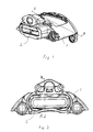
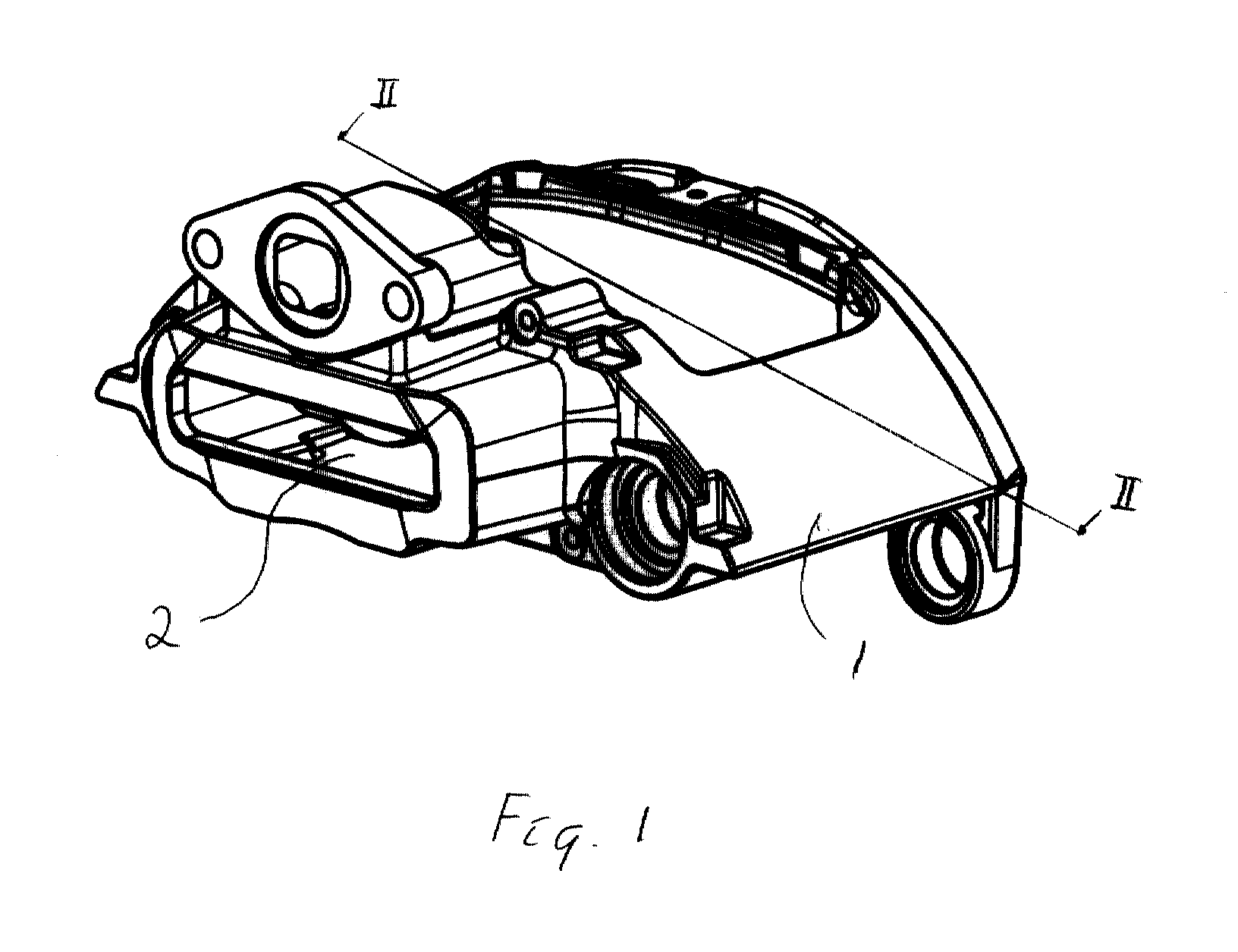
- the caliper will have an open design and is in this description often referred to as an open caliper.
- the caliper In order to give the bearing bracket of the brake mechanism correct and accurate position the caliper has to be machined from the rear. It is difficult and time consuming to machine the caliper from the inside as it will demand the use of an angular cutter and an extensive fixture which is not feasible in line production.
- a further object of the present invention is to facilitate assembly of the brake mechanism inside the caliper.
- the invention makes it possible to assemble the brake mechanism without the use of fastening means between the brake mechanism and the rear of the caliper. This is of advantage as the reaction forces on the fastening means will be considerable at a high braking torque.
- the brake mechanism is held in position by means of a spring urging the mechanism against the caliper.
- the bearing bracket may be made in any optional and suitable material.
- the brake mechanism may be assembled as one unit in the caliper. However, due to the dimensions of the caliper and/or the brake mechanism it may be necessary to assemble the brake mechanism in two or more parts. It may not be physically possible to insert the brake mechanism as one unit.
- the brake mechanism of the present invention is preferably pneumatically actuated, but it may also be hydraulically or electrically actuated.
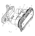
- the caliper 1 Before assembly of the brake mechanism the caliper 1 has to be machined.
- the caliper 1 is furnished with an opening 2 on the rear side, i.e. in the wall furthest from the brake disc (not shown).
- a tool e.g. in the form of a rotary milling tool 3
- the inside of the caliper 1 is machined to give a plane and smooth surface for the brake mechanism.
- the opening 2 of the caliper 1 facilitates the machining of the inside of the caliper 1.
- the brake mechanism After the machining of the inside of the caliper 1 the brake mechanism is assembled.
- the brake mechanism may be assembled as one unit, or in several steps as two or more units.
- the open caliper 1 will surround the brake disc (not shown) on both sides, thus, reaching over the brake disc. Furthermore, the caliper 1 has a cavity 20 for receiving the brake mechanism.
- the brake mechanism comprises a bearing bracket 4, which is received in the opening 2 of the caliper 1.
- the bearing bracket 4 may be made of any optional material.
- the bearing bracket 4 is to withstand the actuating forces of the disc brake.
- a lever 5 and two reset and adjuster shafts 8 form one unit together with the bearing bracket 4.
- the lever 5 is held at the bearing bracket 4 by means of clips (cf. Fig. 5).
- the brake mechanism further comprises a cross bar 6, a closing plate 10, thrust plates, an adjuster mechanism and a synchronisation unit, etc. Some of these parts are not shown in Fig. 4. Said further parts form a second unit of the brake mechanism held together by a brace 12.
- the brake mechanism is assembled in the caliper 1 as one or more units.
- the caliper 1 is machined from the rear side of the caliper 1 to guarantee a correct and accurate position for the bearing bracket 4.'The machining is done in an area on the inside of the caliper 1 surrounding the opening 2.
- the lever 5 and the bearing bracket 4 forms one unit. Corresponding parts are given the same reference signs in the embodiments of both Figs. 4 and 5.
- the bearing bracket 4 holds the lever 5 by means of clips 11.
- the other part of the brake mechanism is held together by means of a brace 12.
- This second unit of the brake mechanism comprises e.g. thrust units 14, a reset shaft 15, an adjuster mechanism 9, synchronisation gears 13, a cross bar 6, a return spring 18, a closing plate 10 and a thrust plate 7.
- the brake mechanism of Fig. 5 may be mounted in the brake caliper 1 as one or two units.
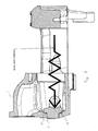
- Fig. 6 the brake mechanism of Fig. 5 is shown in cross section mounted in the brake caliper 1.
- a sealing 19 (indicated in Figs. 6 and 7, respectively) is placed between the bearing bracket 4 and the open caliper 1.
- the sealing 19 between the bearing bracket 4 and the open caliper 1 is received in a groove of the bearing bracket 4 or the caliper 1.
- the groove and thus the sealing 19 may be placed in any position axially or radially in the bearing bracket 4 or caliper 1. If the sealing 19 is placed in a groove of the caliper 1, the sealing 19 is normally mounted by means of the opening 2 of the caliper 1 before assembly of the brake mechanism.
- the cross bar 6 has four protruding parts 17.
- the protruding parts 17 of the cross bar 6 are to abut the inside of the caliper 1 allowing a slight movement between the cross bar 6 and the caliper 1.
- the brake mechanism is assembled without the use of fastening means between the brake mechanism and the rear of the caliper 1.
- the part of the caliper 1 in contact with the protruding parts 17 of the cross bar 6 is machined to give a smooth surface. This machining is also done via the opening 2 of the open caliper 1.
- the bearing bracket 4 is received in the opening 2 of the caliper 1.
- the bearing bracket 4 has a shoulder 16 abutting the inside of the caliper 1 and thus, the bearing bracket 4 is placed in the opening 2 of the caliper 1 from the inside.
- the reaction of the clamp force of the brake is transmitted by means of the shoulder 16 of the bearing bracket 4 to the open caliper 1.
- the force is transmitted in an area surrounding the opening 2.
- the bearing bracket 4 is a loaded part of the brake mechanism the bearing bracket and its shoulder 16 should have enough strength to transmit the force of reaction.
- the module consisting of the lever 5 and bearing bracket 4 is normally first brought into the open caliper 1, then the other module is brought in and the closing plate 10 is fixed to the caliper 1.
- the bearing bracket 4 may be held from the outside while the rest of the brake mechanism is mounted. As stated above the brake mechanism may be inserted as one unit in the caliper. After assembly the brake mechanism will be held together within the brake caliper 1 by screws (not shown) fixing the closing plate 10 to the caliper 1. As indicated in Fig. 7 the bearing bracket 4 is held in position by means of a spring force executed by the return spring 18 (see Fig. 6). The return spring 18 acts between the closing plate 10 and the brake mechanism. The closing plate 10 is fixed to the caliper 1.
- the assembly is facilitated by the possibility to operate from two directions. Thus, it is possible to keep the bearing bracket 4 fixed from the outside until the rest of the mechanism including the return spring 18 has been mounted.
Landscapes
- Engineering & Computer Science (AREA)
- General Engineering & Computer Science (AREA)
- Mechanical Engineering (AREA)
- Braking Arrangements (AREA)
Abstract
Description
Claims (10)
- A method of assembly of a brake mechanism for a disc brake in a caliper (1), which caliper (1) is to surround the brake disc on both sides and has a cavity (20) for receiving the brake mechanism, characterized in that before assembly the inside of the caliper (1) is machined by a tool introduced through an opening (2) in the wall of the caliper (1) furthest from the brake disc.
- The method of claim 1, characterized in that the area surrounding the opening (2) on the inside of the wall is machined to give an accurate bearing surface for a bearing bracket (4) of the brake mechanism and that the bearing mechanism is brought to abutment against the bearing surface by means of the bearing bracket (4) closing the opening (2) of the rear side wall of the caliper (1).
- The method of claim 1 or 2, characterized in that a sealing (19) is placed in a groove on the inside of the caliper (1) by means of the opening before the brake mechanism is assembled.
- The method of claim 1 or 2, characterized in that a sealing (19) is received in a groove of the bearing bracket (4).
- The method of any of the claims 2 to 4, characterized in that the bearing bracket (4) including at least a lever (5) is first mounted as one unit in the caliper (1).
- The method of claim 5, characterized in that the rest of the brake mechanism is then mounted as one unit in the caliper (1) and that the bearing bracket (4) is fixed from the outside until the rest of the mechanism has been mounted.
- A brake caliper (1) for a disc brake, which caliper (1) surrounds the brake disc on both sides and has a cavity (20) for receiving a brake mechanism, characterized in that the caliper (1) has an opening (2) in the wall furthest from the brake disc.
- The caliper (1) of claim 7, characterized in that a bearing bracket (4) of the brake mechanism is to be mounted from the inside of the caliper (1), abutting the wall in the area of the opening (2) and closing said opening (2) and that the bearing bracket (4) is formed as a force transmitting part between the brake mechanism and the caliper (1).
- The caliper of claim 7 or 8, characterized in that a sealing (19) is mounted in a groove on the inside of the caliper (1) by means of the opening (2) of the caliper (1).
- The caliper of claim 7 or 8, characterized in that a sealing (19) is placed between the caliper (1) and the bearing bracket (4) in a groove of a shoulder (15) of the bearing bracket (4).
Applications Claiming Priority (4)
| Application Number | Priority Date | Filing Date | Title |
|---|---|---|---|
| SE0002058A SE516495C2 (en) | 2000-05-31 | 2000-05-31 | Brake mechanism and caliper for a disc brake |
| SE0002058 | 2000-05-31 | ||
| SE0002943A SE522332C2 (en) | 2000-05-31 | 2000-08-18 | Method of mounting a brake mechanism in a caliper and such caliper |
| SE0002943 | 2000-08-18 |
Publications (2)
| Publication Number | Publication Date |
|---|---|
| EP1160480A2 true EP1160480A2 (en) | 2001-12-05 |
| EP1160480A3 EP1160480A3 (en) | 2003-09-17 |
Family
ID=26655132
Family Applications (1)
| Application Number | Title | Priority Date | Filing Date |
|---|---|---|---|
| EP20010112018 Withdrawn EP1160480A3 (en) | 2000-05-31 | 2001-05-23 | Caliper and a method for assembly of a brake mechanism in said caliper |
Country Status (8)
| Country | Link |
|---|---|
| US (1) | US6634468B2 (en) |
| EP (1) | EP1160480A3 (en) |
| KR (1) | KR20010109137A (en) |
| CN (1) | CN1326055A (en) |
| BR (1) | BR0102226A (en) |
| CZ (1) | CZ20011938A3 (en) |
| HU (1) | HUP0102228A2 (en) |
| SE (1) | SE522332C2 (en) |
Cited By (9)
| Publication number | Priority date | Publication date | Assignee | Title |
|---|---|---|---|---|
| US6634468B2 (en) * | 2000-05-31 | 2003-10-21 | Haldex Brake Products Ab | Method for assembly of a brake mechanism in said caliper |
| US6962244B2 (en) * | 2000-05-31 | 2005-11-08 | Haldex Brake Products Ab | Brake mechanism and a method of controlling force amplification |
| DE102008035753A1 (en) | 2008-07-31 | 2010-02-04 | Wabco Radbremsen Gmbh | Method for producing a caliper, machining tool for carrying out the method, brake caliper produced by the method and disc brake with such a caliper |
| EP2546541A1 (en) * | 2011-07-14 | 2013-01-16 | KNORR-BREMSE Systeme für Nutzfahrzeuge GmbH | Composants d'un frein à disque |
| DE202013102651U1 (en) | 2013-01-09 | 2013-07-25 | Knorr-Bremse Systeme für Nutzfahrzeuge GmbH | Disc brake for a commercial vehicle |
| WO2013143988A1 (en) * | 2012-03-26 | 2013-10-03 | Knorr-Bremse Systeme für Nutzfahrzeuge GmbH | Brake application device of a disk brake |
| CN106002251A (en) * | 2016-07-06 | 2016-10-12 | 苏州科技学院 | Assembly line and assembly method for front calipers |
| WO2017036765A1 (en) * | 2015-08-31 | 2017-03-09 | Knorr-Bremse Systeme für Nutzfahrzeuge GmbH | Disc brake having a synchronization unit |
| WO2018033178A1 (en) * | 2016-08-16 | 2018-02-22 | Bpw Bergische Achsen Kg | Method for machining the interior of a brake caliper of a disc brake |
Families Citing this family (16)
| Publication number | Priority date | Publication date | Assignee | Title |
|---|---|---|---|---|
| SE516495C2 (en) * | 2000-05-31 | 2002-01-22 | Haldex Brake Prod Ab | Brake mechanism and caliper for a disc brake |
| DE10152248B4 (en) * | 2001-10-23 | 2006-03-16 | Knorr-Bremse Systeme für Nutzfahrzeuge GmbH | Disc brake with electric motor operated adjustment system |
| GB0301798D0 (en) * | 2003-01-25 | 2003-02-26 | Meritor Heavy Vehicle Braking | Force transmission device for a disc brake |
| USD488414S1 (en) | 2003-03-24 | 2004-04-13 | Akebono Corporation (North America) | Opening in a brake caliper |
| USD515482S1 (en) | 2003-03-24 | 2006-02-21 | Akebono Corporation | Opening in a brake caliper |
| USD492229S1 (en) | 2003-03-24 | 2004-06-29 | Akebono Corporation (North America) | Brake caliper |
| USD493754S1 (en) | 2003-03-24 | 2004-08-03 | Akebono Corporation (North America) | Brake caliper |
| USD488750S1 (en) | 2003-03-24 | 2004-04-20 | Akebono Corporation (North America) | Opening in a brake caliper |
| US20050230197A1 (en) * | 2004-04-14 | 2005-10-20 | Jedele Philip N | One piece sliding brake caliper |
| EP2639473A1 (en) | 2012-03-16 | 2013-09-18 | Meritor Heavy Vehicle Braking Systems (UK) Limited | Disc brake caliper |
| DE102012108670A1 (en) * | 2012-09-17 | 2014-03-20 | Knorr-Bremse Systeme für Nutzfahrzeuge GmbH | Pneumatically or electromechanically actuated disc brake |
| JP6572102B2 (en) | 2015-04-27 | 2019-09-04 | 曙ブレーキ工業株式会社 | Disc brake device |
| US20170067522A1 (en) * | 2015-09-03 | 2017-03-09 | Bendix Spicer Foundation Brake Llc | Brake actuator apparatus for an air disc brake of a vehicle air braking system |
| JP6633427B2 (en) * | 2016-03-04 | 2020-01-22 | Ntn株式会社 | Electric brake device |
| DE102016116793A1 (en) * | 2016-09-08 | 2018-03-08 | Knorr-Bremse Systeme für Nutzfahrzeuge GmbH | Brake caliper of a disc brake |
| DE102023103290B3 (en) * | 2023-02-10 | 2024-07-18 | Hl Mando Corporation | Floating brake caliper with plate-shaped area for contact with a brake pad and tool and method for machining the same |
Family Cites Families (57)
| Publication number | Priority date | Publication date | Assignee | Title |
|---|---|---|---|---|
| DE1189333B (en) | 1960-08-16 | 1965-03-18 | Teves Kg Alfred | Partly lined disc brake |
| DE1625826A1 (en) | 1967-09-15 | 1970-02-05 | Teves Gmbh Alfred | Partly lined disc brake |
| FR2082723A5 (en) | 1970-03-25 | 1971-12-10 | Dba | |
| DE2057322C3 (en) | 1970-11-21 | 1981-03-12 | Alfred Teves Gmbh, 6000 Frankfurt | Actuating device for a partially lined disc brake |
| US3724616A (en) | 1971-04-22 | 1973-04-03 | Bendix Corp | Tandem cylinder disc brake |
| US3800923A (en) * | 1972-02-14 | 1974-04-02 | Dayton Steel Foundry Co | Disc brake caliper and friction pad mounting means |
| US3937304A (en) | 1972-04-11 | 1976-02-10 | Girling Limited | Disc brake calipers |
| US3830343A (en) | 1972-12-12 | 1974-08-20 | Goodrich Co B F | Disc brake with adjustable cam operator and thrust distributer |
| US3837437A (en) | 1973-01-22 | 1974-09-24 | Airheart Prod | Ratchet actuated brake wear compensation |
| CH585326A5 (en) | 1974-12-06 | 1977-02-28 | Habegger Ag Maschf | |
| US3967705A (en) | 1975-04-02 | 1976-07-06 | The Bendix Corporation | Application adjuster for disc brake |
| CA1030881A (en) | 1975-04-02 | 1978-05-09 | Donald D. Johannesen | Mechanically actuated disc brake |
| US4036329A (en) | 1975-11-12 | 1977-07-19 | Rockwell International Corporation | Disc brake with rotary cam actuated reciprocating pistons |
| US4018310A (en) | 1976-03-15 | 1977-04-19 | The Bendix Corporation | Disc brake |
| US4071118A (en) | 1976-10-22 | 1978-01-31 | The Bendix Corporation | Variable adjuster for disc brake |
| US4184571A (en) | 1976-12-20 | 1980-01-22 | Tokico Ltd. | Disc Brake |
| US4222310A (en) | 1978-12-04 | 1980-09-16 | Eaton Corporation | Brake actuator fastener assembly |
| AU6171580A (en) | 1979-08-30 | 1981-03-05 | Lucas Industries Limited | Brake adjusters |
| DE3026817A1 (en) * | 1980-07-16 | 1982-02-11 | Alfred Teves Gmbh, 6000 Frankfurt | FLOATING SADDLE PARTIAL DISC BRAKE, ESPECIALLY FOR MOTOR VEHICLES |
| GB2090355A (en) | 1980-12-12 | 1982-07-07 | Lucas Industries Ltd | Improvements relating to brake adjusters |
| GB2093934B (en) | 1981-03-03 | 1985-01-30 | Lucas Industries Ltd | Improvements relating to the construction of pin sliding calipers |
| FR2504076B1 (en) | 1981-04-17 | 1985-06-14 | Valeo | MECHANICAL BRAKE CONTROL CONSISTING OF AN ECCENTRIC |
| EP0070106A1 (en) | 1981-07-14 | 1983-01-19 | Automotive Products Public Limited Company | Disc brakes |
| FR2548309B1 (en) | 1983-06-30 | 1985-12-13 | Valeo | COUPLING APPARATUS SUCH AS BRAKE OR THE LIKE HAVING A WEAR RETRACTOR |
| FR2554194B1 (en) | 1983-10-28 | 1986-01-17 | Dba | AUTOMATICALLY ADJUSTABLE BRAKE MOTOR |
| FR2564925B1 (en) | 1984-05-23 | 1986-10-03 | Dba | AUTOMATICALLY ADJUSTABLE DISC BRAKE |
| DE3438209C2 (en) | 1984-10-18 | 1994-06-23 | Teves Gmbh Alfred | Disc brake, in particular for motor vehicles |
| DE8434025U1 (en) | 1984-11-20 | 1986-03-27 | Lucas Industries P.L.C., Birmingham, West Midlands | Brake actuator |
| JPH0346264Y2 (en) | 1985-03-28 | 1991-09-30 | ||
| DE3610569C2 (en) | 1986-03-27 | 1994-02-17 | Knorr Bremse Ag | Disc brake for vehicles |
| GB8622617D0 (en) | 1986-09-19 | 1986-10-22 | Lucas Ind Plc | Disc brakes |
| DE8633923U1 (en) | 1986-12-18 | 1988-04-21 | Lucas Industries P.L.C., Birmingham, West Midlands | Actuating device with automatic adjustment for brakes, in particular of heavy-duty vehicles |
| DE3716202C3 (en) | 1987-05-14 | 2000-03-09 | Knorr Bremse Systeme | Disc brake for vehicles |
| JPS646423A (en) | 1987-06-26 | 1989-01-11 | Sato Road Co Ltd | Water pervious water purifying road structure |
| JPH032022A (en) | 1989-05-31 | 1991-01-08 | Rika Kogyo Kk | Device for controlling picture display in extrusion molding line |
| DE9000257U1 (en) | 1990-01-11 | 1991-05-16 | Lucas Industries P.L.C., Birmingham, West Midlands | Actuating device for a vehicle brake, in particular a disc brake |
| JP2888921B2 (en) | 1990-05-08 | 1999-05-10 | パイオニア株式会社 | Disc playback device |
| JPH0429141A (en) | 1990-05-24 | 1992-01-31 | Seiko Epson Corp | Image forming device and heat developing device |
| DE4031616C2 (en) | 1990-10-05 | 1999-11-25 | Perrot Bremse Gmbh Deutsche | Automatic adjustment device for a mechanically operated sliding calliper disc brake |
| DE4032886A1 (en) | 1990-10-17 | 1992-04-23 | Knorr Bremse Ag | DISC BRAKE FOR VEHICLES, IN PARTICULAR ROAD VEHICLES |
| DE4032885A1 (en) | 1990-10-17 | 1992-04-23 | Knorr Bremse Ag | DISC BRAKE FOR VEHICLES, IN PARTICULAR ROAD VEHICLES |
| GB9100944D0 (en) | 1991-01-16 | 1991-02-27 | Lucas Ind Plc | Brake actuator |
| DE4131631C2 (en) | 1991-09-23 | 1999-05-27 | Julius Dipl Ing Nadas | Mechanical application device for vehicle brakes |
| DE4231560C2 (en) | 1992-09-21 | 2002-07-11 | Perrot Bremse Gmbh Deutsche | Actuator for a sliding caliper disc brake |
| DE4307019B4 (en) | 1993-03-05 | 2006-06-14 | Deutsche Perrot-Bremse Gmbh | Clamping device for a disc brake |
| JPH07208514A (en) * | 1994-01-19 | 1995-08-11 | Tokico Ltd | Disc brake |
| DE4430258C1 (en) | 1994-08-25 | 1996-01-04 | Perrot Bremsen Gmbh | Actuating mechanism for disc brake |
| SE505339C2 (en) | 1994-10-24 | 1997-08-11 | Haldex Ab | Disc brake caliper |
| DE19515063C2 (en) | 1995-04-27 | 2002-06-06 | Knorr Bremse Systeme | Disc brake for vehicles, in particular road vehicles |
| DE29508001U1 (en) * | 1995-05-15 | 1996-09-12 | Lucas Industries P.L.C., Solihull, West Midlands | Disc brake application device and seal therefor |
| US5590742A (en) | 1995-06-07 | 1997-01-07 | Itt Automotive, Inc. | Stamped caliper adapter |
| GB9716363D0 (en) * | 1997-08-02 | 1997-10-08 | Lucas Ind Plc | Improvements relating to disc brakes |
| US5957245A (en) * | 1997-08-05 | 1999-09-28 | Itt Manufacturing Enterprises Inc. | Disc brake, disc brake caliper and disc brake shoe |
| US6000506A (en) * | 1998-02-23 | 1999-12-14 | General Motors Corporation | Disc brake caliper |
| US5960914A (en) | 1999-02-02 | 1999-10-05 | Goshen Industries Inc. | Mechanical disc brake |
| AUPP995099A0 (en) * | 1999-04-26 | 1999-05-20 | Pbr Automotive Pty Ltd | Disc brake caliper |
| SE522332C2 (en) * | 2000-05-31 | 2004-02-03 | Haldex Brake Prod Ab | Method of mounting a brake mechanism in a caliper and such caliper |
-
2000
- 2000-08-18 SE SE0002943A patent/SE522332C2/en not_active IP Right Cessation
-
2001
- 2001-05-23 EP EP20010112018 patent/EP1160480A3/en not_active Withdrawn
- 2001-05-25 US US09/865,259 patent/US6634468B2/en not_active Expired - Fee Related
- 2001-05-29 HU HU0102228A patent/HUP0102228A2/en unknown
- 2001-05-29 KR KR1020010029618A patent/KR20010109137A/en not_active Withdrawn
- 2001-05-31 BR BR0102226A patent/BR0102226A/en not_active Application Discontinuation
- 2001-05-31 CN CN01121308A patent/CN1326055A/en active Pending
- 2001-05-31 CZ CZ20011938A patent/CZ20011938A3/en unknown
Cited By (19)
| Publication number | Priority date | Publication date | Assignee | Title |
|---|---|---|---|---|
| US6634468B2 (en) * | 2000-05-31 | 2003-10-21 | Haldex Brake Products Ab | Method for assembly of a brake mechanism in said caliper |
| US6962244B2 (en) * | 2000-05-31 | 2005-11-08 | Haldex Brake Products Ab | Brake mechanism and a method of controlling force amplification |
| DE102008035753A1 (en) | 2008-07-31 | 2010-02-04 | Wabco Radbremsen Gmbh | Method for producing a caliper, machining tool for carrying out the method, brake caliper produced by the method and disc brake with such a caliper |
| EP2546541A1 (en) * | 2011-07-14 | 2013-01-16 | KNORR-BREMSE Systeme für Nutzfahrzeuge GmbH | Composants d'un frein à disque |
| WO2013143988A1 (en) * | 2012-03-26 | 2013-10-03 | Knorr-Bremse Systeme für Nutzfahrzeuge GmbH | Brake application device of a disk brake |
| DE202013102651U1 (en) | 2013-01-09 | 2013-07-25 | Knorr-Bremse Systeme für Nutzfahrzeuge GmbH | Disc brake for a commercial vehicle |
| DE102013100173A1 (en) | 2013-01-09 | 2014-07-10 | Knorr-Bremse Systeme für Nutzfahrzeuge GmbH | Disc brake for a commercial vehicle |
| DE102013100173B4 (en) | 2013-01-09 | 2021-07-15 | Knorr-Bremse Systeme für Nutzfahrzeuge GmbH | Disc brake for a commercial vehicle |
| WO2017036765A1 (en) * | 2015-08-31 | 2017-03-09 | Knorr-Bremse Systeme für Nutzfahrzeuge GmbH | Disc brake having a synchronization unit |
| US10626940B2 (en) | 2015-08-31 | 2020-04-21 | Knorr-Bremse Systeme Fuer Nutzfahrzeuge Gmbh | Disc brake having a synchronization unit |
| CN106002251B (en) * | 2016-07-06 | 2018-02-09 | 苏州科技学院 | Preceding clamp assembly line and assembly method |
| CN106002251A (en) * | 2016-07-06 | 2016-10-12 | 苏州科技学院 | Assembly line and assembly method for front calipers |
| WO2018033178A1 (en) * | 2016-08-16 | 2018-02-22 | Bpw Bergische Achsen Kg | Method for machining the interior of a brake caliper of a disc brake |
| DE102016115176A1 (en) * | 2016-08-16 | 2018-02-22 | Bpw Bergische Achsen Kg | Method for internal machining of a brake caliper of a disc brake |
| CN109715970A (en) * | 2016-08-16 | 2019-05-03 | Bpw 矿用轴公司 | Method for machining the inside of a disc brake caliper |
| EP3500769B1 (en) | 2016-08-16 | 2020-04-01 | BPW Bergische Achsen KG | Method for machining the interior of a brake caliper of a disc brake |
| US10682711B2 (en) | 2016-08-16 | 2020-06-16 | Bpw Bergische Achsen Kg | Method for machining the interior of a brake caliper of a disc brake |
| CN109715970B (en) * | 2016-08-16 | 2021-05-07 | Bpw 矿用轴公司 | Method for machining the inside of a disc brake caliper |
| EP3500769B2 (en) † | 2016-08-16 | 2023-08-30 | BPW Bergische Achsen KG | Method for machining the interior of a brake caliper of a disc brake |
Also Published As
| Publication number | Publication date |
|---|---|
| SE522332C2 (en) | 2004-02-03 |
| EP1160480A3 (en) | 2003-09-17 |
| HU0102228D0 (en) | 2001-08-28 |
| SE0002943L (en) | 2001-12-01 |
| KR20010109137A (en) | 2001-12-08 |
| CN1326055A (en) | 2001-12-12 |
| US6634468B2 (en) | 2003-10-21 |
| US20020014376A1 (en) | 2002-02-07 |
| BR0102226A (en) | 2002-02-13 |
| SE0002943D0 (en) | 2000-08-18 |
| HUP0102228A2 (en) | 2002-05-29 |
| CZ20011938A3 (en) | 2002-01-16 |
Similar Documents
| Publication | Publication Date | Title |
|---|---|---|
| EP1160480A2 (en) | Caliper and a method for assembly of a brake mechanism in said caliper | |
| USRE38874E1 (en) | Disc brake for vehicles having insertable actuator | |
| US6668981B2 (en) | Disc brake comprising a brake mechanism | |
| CN100398864C (en) | Method for controlling an adjustment system of a disc brake | |
| JP2019505427A (en) | Electric drum brake system with a streamlined electric parking brake actuator | |
| BR9904687A (en) | Hydraulic release system | |
| US20060054425A1 (en) | Floating caliper-type disc brake | |
| HUP0102230A2 (en) | Brake mechanism and caliper for a disc brake | |
| US7422091B2 (en) | Disc brake having an electromotively actuated adjusting system | |
| CN1005124B (en) | Disc brake with parking brake holding device | |
| EP3074284A1 (en) | Ball nut assembly for an electromechanically actuable parking brake assembly of a brake assembly | |
| JP2004286216A (en) | One piece sliding brake caliper | |
| EP1892433A2 (en) | Disc brake actuator mounting arrangement | |
| US6068091A (en) | Externally mounted bracket system for disc brakes | |
| DE19880620T1 (en) | Clutch mechanism for a friction clutch with low release force, especially for motor vehicles | |
| GB2236825B (en) | An actuating assembly for a clutch release bearing,in particular for an automotive vehicle | |
| EP0108680A1 (en) | A caliper for a disc brake and a method for manufacturing the same | |
| US4094389A (en) | Disc brakes | |
| PL166326B1 (en) | Disc brake with partial lining and brake shoe for partially lined disc brakes | |
| US20180306255A1 (en) | Disc brake and method of producing the disc brake | |
| US20190203786A1 (en) | Brake Caliper of a Disc Brake | |
| TW201842267A (en) | Cylinder lock | |
| US20040060780A1 (en) | Parking brake and control device therefor | |
| EP3772599B1 (en) | Brake caliper for a vehicle brake and method for assembling a brake caliper | |
| BR9805456A (en) | Method for installing a carrier plate and wedge lock assembly. |
Legal Events
| Date | Code | Title | Description |
|---|---|---|---|
| PUAI | Public reference made under article 153(3) epc to a published international application that has entered the european phase |
Free format text: ORIGINAL CODE: 0009012 |
|
| AK | Designated contracting states |
Kind code of ref document: A2 Designated state(s): AT BE CH CY DE DK ES FI FR GB GR IE IT LI LU MC NL PT SE TR |
|
| AX | Request for extension of the european patent |
Free format text: AL;LT;LV;MK;RO;SI |
|
| PUAL | Search report despatched |
Free format text: ORIGINAL CODE: 0009013 |
|
| AK | Designated contracting states |
Kind code of ref document: A3 Designated state(s): AT BE CH CY DE DK ES FI FR GB GR IE IT LI LU MC NL PT SE TR |
|
| AX | Request for extension of the european patent |
Extension state: AL LT LV MK RO SI |
|
| RIC1 | Information provided on ipc code assigned before grant |
Ipc: 7F 16D 55/225 B Ipc: 7F 16D 65/56 B Ipc: 7F 16D 65/18 A |
|
| AKX | Designation fees paid | ||
| REG | Reference to a national code |
Ref country code: DE Ref legal event code: 8566 |
|
| STAA | Information on the status of an ep patent application or granted ep patent |
Free format text: STATUS: THE APPLICATION IS DEEMED TO BE WITHDRAWN |
|
| 18D | Application deemed to be withdrawn |
Effective date: 20040318 |