EP1160432A1 - Turboréacteur - Google Patents
Turboréacteur Download PDFInfo
- Publication number
- EP1160432A1 EP1160432A1 EP00870117A EP00870117A EP1160432A1 EP 1160432 A1 EP1160432 A1 EP 1160432A1 EP 00870117 A EP00870117 A EP 00870117A EP 00870117 A EP00870117 A EP 00870117A EP 1160432 A1 EP1160432 A1 EP 1160432A1
- Authority
- EP
- European Patent Office
- Prior art keywords
- prechamber
- combustion
- compressor
- flow
- chamber
- Prior art date
- Legal status (The legal status is an assumption and is not a legal conclusion. Google has not performed a legal analysis and makes no representation as to the accuracy of the status listed.)
- Granted
Links
- 238000002485 combustion reaction Methods 0.000 claims abstract description 110
- 239000000567 combustion gas Substances 0.000 claims abstract description 27
- 229920001169 thermoplastic Polymers 0.000 claims abstract description 27
- 239000004416 thermosoftening plastic Substances 0.000 claims abstract description 27
- 238000000034 method Methods 0.000 claims abstract description 13
- 239000007789 gas Substances 0.000 claims description 42
- 239000000446 fuel Substances 0.000 claims description 27
- 239000012815 thermoplastic material Substances 0.000 claims description 23
- 238000002844 melting Methods 0.000 claims description 15
- 230000008018 melting Effects 0.000 claims description 15
- 239000007800 oxidant agent Substances 0.000 claims description 15
- 239000000463 material Substances 0.000 claims description 11
- 238000003763 carbonization Methods 0.000 claims description 9
- 239000000203 mixture Substances 0.000 claims description 5
- 230000001590 oxidative effect Effects 0.000 claims description 5
- 239000004020 conductor Substances 0.000 claims description 4
- 239000011248 coating agent Substances 0.000 claims description 3
- 238000000576 coating method Methods 0.000 claims description 3
- 230000035515 penetration Effects 0.000 claims description 3
- 239000003054 catalyst Substances 0.000 claims description 2
- 239000004033 plastic Substances 0.000 claims description 2
- 238000010438 heat treatment Methods 0.000 description 8
- 239000012943 hotmelt Substances 0.000 description 5
- 238000002347 injection Methods 0.000 description 5
- 239000007924 injection Substances 0.000 description 5
- 238000004519 manufacturing process Methods 0.000 description 5
- 230000006835 compression Effects 0.000 description 4
- 238000007906 compression Methods 0.000 description 4
- 239000002184 metal Substances 0.000 description 3
- 238000003780 insertion Methods 0.000 description 2
- 230000037431 insertion Effects 0.000 description 2
- 239000007788 liquid Substances 0.000 description 2
- VNWKTOKETHGBQD-UHFFFAOYSA-N methane Chemical compound C VNWKTOKETHGBQD-UHFFFAOYSA-N 0.000 description 2
- 238000002156 mixing Methods 0.000 description 2
- 238000003756 stirring Methods 0.000 description 2
- 229910045601 alloy Inorganic materials 0.000 description 1
- 239000000956 alloy Substances 0.000 description 1
- QVGXLLKOCUKJST-UHFFFAOYSA-N atomic oxygen Chemical compound [O] QVGXLLKOCUKJST-UHFFFAOYSA-N 0.000 description 1
- 239000011324 bead Substances 0.000 description 1
- 230000015572 biosynthetic process Effects 0.000 description 1
- 230000003197 catalytic effect Effects 0.000 description 1
- 238000010790 dilution Methods 0.000 description 1
- 239000012895 dilution Substances 0.000 description 1
- 229920001971 elastomer Polymers 0.000 description 1
- 239000000806 elastomer Substances 0.000 description 1
- 239000012530 fluid Substances 0.000 description 1
- 230000004927 fusion Effects 0.000 description 1
- 239000008240 homogeneous mixture Substances 0.000 description 1
- 239000003350 kerosene Substances 0.000 description 1
- 238000012423 maintenance Methods 0.000 description 1
- 239000011159 matrix material Substances 0.000 description 1
- 229910001092 metal group alloy Inorganic materials 0.000 description 1
- 239000012768 molten material Substances 0.000 description 1
- 239000001301 oxygen Substances 0.000 description 1
- 229910052760 oxygen Inorganic materials 0.000 description 1
- -1 petrol Substances 0.000 description 1
- 239000003208 petroleum Substances 0.000 description 1
- 238000003825 pressing Methods 0.000 description 1
- 230000001141 propulsive effect Effects 0.000 description 1
- 230000005855 radiation Effects 0.000 description 1
- 238000005096 rolling process Methods 0.000 description 1
- 238000002604 ultrasonography Methods 0.000 description 1
- 238000011144 upstream manufacturing Methods 0.000 description 1
- 238000009834 vaporization Methods 0.000 description 1
- 230000008016 vaporization Effects 0.000 description 1
Images


Classifications
-
- F—MECHANICAL ENGINEERING; LIGHTING; HEATING; WEAPONS; BLASTING
- F01—MACHINES OR ENGINES IN GENERAL; ENGINE PLANTS IN GENERAL; STEAM ENGINES
- F01D—NON-POSITIVE DISPLACEMENT MACHINES OR ENGINES, e.g. STEAM TURBINES
- F01D1/00—Non-positive-displacement machines or engines, e.g. steam turbines
- F01D1/24—Non-positive-displacement machines or engines, e.g. steam turbines characterised by counter-rotating rotors subjected to same working fluid stream without intermediate stator blades or the like
-
- F—MECHANICAL ENGINEERING; LIGHTING; HEATING; WEAPONS; BLASTING
- F02—COMBUSTION ENGINES; HOT-GAS OR COMBUSTION-PRODUCT ENGINE PLANTS
- F02C—GAS-TURBINE PLANTS; AIR INTAKES FOR JET-PROPULSION PLANTS; CONTROLLING FUEL SUPPLY IN AIR-BREATHING JET-PROPULSION PLANTS
- F02C3/00—Gas-turbine plants characterised by the use of combustion products as the working fluid
- F02C3/14—Gas-turbine plants characterised by the use of combustion products as the working fluid characterised by the arrangement of the combustion chamber in the plant
- F02C3/145—Gas-turbine plants characterised by the use of combustion products as the working fluid characterised by the arrangement of the combustion chamber in the plant the combustion chamber being in the reverse flow-type
-
- F—MECHANICAL ENGINEERING; LIGHTING; HEATING; WEAPONS; BLASTING
- F23—COMBUSTION APPARATUS; COMBUSTION PROCESSES
- F23R—GENERATING COMBUSTION PRODUCTS OF HIGH PRESSURE OR HIGH VELOCITY, e.g. GAS-TURBINE COMBUSTION CHAMBERS
- F23R3/00—Continuous combustion chambers using liquid or gaseous fuel
- F23R3/28—Continuous combustion chambers using liquid or gaseous fuel characterised by the fuel supply
- F23R3/34—Feeding into different combustion zones
- F23R3/346—Feeding into different combustion zones for staged combustion
-
- F—MECHANICAL ENGINEERING; LIGHTING; HEATING; WEAPONS; BLASTING
- F23—COMBUSTION APPARATUS; COMBUSTION PROCESSES
- F23R—GENERATING COMBUSTION PRODUCTS OF HIGH PRESSURE OR HIGH VELOCITY, e.g. GAS-TURBINE COMBUSTION CHAMBERS
- F23R3/00—Continuous combustion chambers using liquid or gaseous fuel
- F23R3/40—Continuous combustion chambers using liquid or gaseous fuel characterised by the use of catalytic means
-
- F—MECHANICAL ENGINEERING; LIGHTING; HEATING; WEAPONS; BLASTING
- F23—COMBUSTION APPARATUS; COMBUSTION PROCESSES
- F23R—GENERATING COMBUSTION PRODUCTS OF HIGH PRESSURE OR HIGH VELOCITY, e.g. GAS-TURBINE COMBUSTION CHAMBERS
- F23R3/00—Continuous combustion chambers using liquid or gaseous fuel
- F23R3/42—Continuous combustion chambers using liquid or gaseous fuel characterised by the arrangement or form of the flame tubes or combustion chambers
- F23R3/54—Reverse-flow combustion chambers
-
- F—MECHANICAL ENGINEERING; LIGHTING; HEATING; WEAPONS; BLASTING
- F05—INDEXING SCHEMES RELATING TO ENGINES OR PUMPS IN VARIOUS SUBCLASSES OF CLASSES F01-F04
- F05D—INDEXING SCHEME FOR ASPECTS RELATING TO NON-POSITIVE-DISPLACEMENT MACHINES OR ENGINES, GAS-TURBINES OR JET-PROPULSION PLANTS
- F05D2260/00—Function
- F05D2260/60—Fluid transfer
- F05D2260/601—Fluid transfer using an ejector or a jet pump
Definitions
- the present invention relates to a turbojet engine.
- Document GB-A-650,661 discloses a turbojet engine comprising at least a compressor sucking and compressing air so as to form at least one flow main compressed air, one or more combustion chambers, at least one means to bring fuel into the combustion chamber (s), at least one means for bringing an oxidizer into the combustion chamber (s), and to the minus one turbine receiving the combustion gases from the chamber (s) combustion, driving the compressor and followed by an expansion nozzle.
- the main flow of air from the compressor essentially serves for the combustion of fuel and it is introduced into the combustion chamber (s) only greatly slowed down and disturbed before serving for the stirring necessary for complete combustion and moving on to across the turbine.
- the necessary disturbance of the main flow is required to ensure a substantially homogeneous mixture with the fuel, attachment and maintenance of the flame, complete progression of combustion, while ensuring an acceptable temperature for the walls of the chamber (s) s) and for the turbine (s).
- the turbojet engine according to the invention comprises at less a combustion prechamber comprising means or means of an oxidizer and a fuel.
- the combustion prechamber includes or is associated with a means for supplying the combustion gases from the prechamber in at least one combustion chamber.
- the means for bringing the combustion gases from the prechamber into the chamber combustion is part of the prechamber.
- the prechamber has advantageously a zone of oxidant-fuel mixture and their precombustion, possibly preceded by an oxidizer-fuel premix substantially free of combustion.
- the turbojet engine according to the invention has the advantage of allowing by a prechamber of reduced volume and which is advantageously angled with respect to the combustion chamber, a reduction the axial size (in the longitudinal direction) of the turbojet engine, as well as a reduction of the pressure drop of gases in their transit in all areas necessary for complete combustion.
- the turbojet engine has a means to direct at least part of the main compressed air flow from the compressor in the combustion chamber, said means being arranged relative to the means for bringing combustion gases into the combustion chamber so at least part of the main compressed air flow from the compressor advantageously directed directly into the combustion chamber creates at least one suction of the combustion gases from the prechamber to ensure at least the transit of gases between the prechamber and the chamber, as well as to ensure in said combustion chamber additional combustion, so advantageous substantially complete, unburned fuel in the prechamber, this suction being advantageously combined with a mixture of the gases of combustion with part of the main flow of compressed air in the combustion.
- said means is arranged to also ensure an air supply in the prechamber.
- the turbojet engine can include one or more pre-chambers of combustion associated with one or more combustion chambers.
- the turbojet engine comprises several separate combustion pre-chambers, the combustion gases of which are brought into the same combustion chamber, and / or several separate combustion chambers, including combustion gases are brought into several separate combustion chambers, in particular including the combustion gases from each prechamber are brought into a separate combustion.
- the prechamber therefore designates a or several separate pre-chambers, in particular arranged in parallel
- the combustion chamber means one or more separate chambers, in particular arranged in parallel.
- the compressor and / or the means for directing at least one part of the main compressed air flow from the compressor in the chamber combustion are arranged to ensure a speed for this part of the flow main introduced into the chamber at least greater than the velocity of the gases leaving of the prechamber, advantageously at least twice the speed gases exiting the prechamber, preferably at least five times greater than the velocity of the gases leaving the prechamber, and to ensure that the prechamber in relation to the room, in particular in relation to its surroundings or neighborhood and to the combustion chamber.
- the means directing at least part of the main air flow compressed from the compressor is constituted by a wall of the means ensuring the passage of gases from the prechamber into the chamber or through a wall associated with the means ensuring the passage of gases from the prechamber into the chamber.
- the means for directing at least part of the main flow compressed air from the compressor in the combustion chamber is arranged so that substantially all of the compressed air flow leaving the compressor is brought in to pass through the combustion chamber substantially without disturbance significant of its speed and direction.
- This embodiment is advantageous because it reduces the pressure drop during the passage of air and gases in all the means necessary for combustion, pressure losses which are far from negligible in conventional combustion chambers.
- the speed of the main flow of compressed air passing through the combustion is at least equal to 75% of the initial speed of the main incoming flow in the combustion chamber, in particular at least equal to 85% of the speed initial main flow entering the combustion chamber, preferably substantially equal to the initial speed of the main flow entering the combustion.
- the fuel supply means and of oxidizer in the prechamber are closer to the turbine of the turbojet or are further from the compressor.
- the prechamber with its means for supplying fuel and oxidizer is advantageously arranged so that the flow of combustion gases in the prechamber is essentially at against the flow of gas into the combustion chamber.
- turbojet engine it is possible to use as fuel liquid type fuels, such as petrol, petroleum, kerosene, etc., as well as gaseous fuels such as methane, etc.
- fuel liquid type fuels such as petrol, petroleum, kerosene, etc.
- gaseous fuels such as methane, etc.
- the supply is carried out by means of a conduit in contact with a part or hot zone of the turbojet engine to ensure natural vaporization of the fuel at the time of its injection into the prechamber.
- air from the compressor and / or external compressed air (not coming from the turbojet compressor) and / or any other suitable oxidizer.
- partially or completely air is used directly from the compressor and / or from the main compressed air flow after it has previously passed through the combustion chamber.
- Air from compressor can be brought into the prechamber without passing through the combustion, this air being for example mainly supplied by one or more conduits or orifices, advantageously substantially adjacent to the axis of the turbojet, at the prechamber by the sides of the prechamber facing the axis of the turbojet engine and / or on the front face of the prechamber (face facing the compressor) and / or by the rear face or the bottom of the prechamber.
- the turbojet engine according to the invention has means ensuring a passage of compressed air from the compressor in the prechamber, said means being adapted so that the compressed air flow ratio from the compressor introduced into the prechamber / compressed air flow from the compressor introduced into the chamber is less than 1/5, advantageously less than 1/8, preferably less than 1/10, even more so preferred less than 1/20.
- the report will be adjusted as necessary, particularly in as a function of the maximum admissible temperature in the turbine.
- the turbojet engine has means ensuring a passage of gas from the chamber to the prechamber, said means being arranged for gases from the chamber to enter the prechamber between the fuel supply means in the prechamber and the means for bring the combustion gases from the prechamber into the combustion chamber.
- the passage of gas from the combustion chamber to the prechamber and / or the passage air directly from the compressor in the prechamber ensures the precombustion by better fuel-oxidant mixing in the prechamber and / or by the gradual increase in the proportion of air in the process of precombustion.
- the means (which advantageously form a wall of the prechamber) bringing the combustion gases from the prechamber into the combustion chamber comprise or form means dividing the air flow upstream compressed (from the compressor) in a first flow entering the chamber and in a second flow supplying the prechamber through sound orifices envelope, said second flow having a flow rate lower than the first flow, in particular significantly lower than the first flow allowing the prechamber to have a volume reduced.
- the prechamber advantageously comprises means for bringing the said second flow or part of it, in particular in one or more means to bring the combustion gases from the prechamber to the combustion chamber to feed it or to supply them with oxidizer.
- the means or means sharing the two air flows is adapted so that the second flow / first flow ratio is less than 1: 5, advantageously less than 1: 8, preferably less than 1: 10, in particular less than 1: 20.
- this or these means bring air compressed in the prechamber or in its part forming the means guiding the gases of combustion of the prechamber in the room.
- This air supply ensures mixing air and gases with the fuel and thus allows pre-combustion.
- the way bringing the compressed air is or forms for example one or more air injectors outer tablet or one or more holes drilled on the various faces of the envelope from the prechamber.
- turbojet engine is provided with means ensuring the passage of gas from the room towards the prechamber, it is advantageous that these means are arranged to not be located in the wake (or extension) of the gas flow leaving the medium of the prechamber guiding the gases from the prechamber into the combustion chamber. This ensures that the gases from the chamber passing through the prechamber do not contain little combustion gas or consist mainly of air from the main flow of the compressor.
- At least part of the prechamber, in particular at least part of its means guiding its gases combustion from the prechamber to the combustion chamber has at least one coating containing at least one combustion catalyst.
- the compressor comprises a stator at least partially rotary (for example fully rotary), in particular counter-rotating (for example fully contra-rotating).
- the stator has a fixed section and a rotary section, in particular counter-rotating, this movable section of the stator being connected to a turbine which his own.
- the outer wall of the rotary stator, in particular counter-rotating, is possibly attached to an auxiliary compressor rotor or to a blower auxiliary or to elements forming an auxiliary compressor or blower.
- This auxiliary compressor or blower forms an external compressor or blower, advantageously placed within the axial or longitudinal limits of the compressor main to ensure reduced longitudinal dimensions, the air leaving the auxiliary compressor or auxiliary blower advantageously used for dilute the gases ejected from the central body of the turbo, thereby improving the propulsion efficiency.
- the compressor comprises a stator with blades and a rotor with blades, the rotor and / or the stator comprising a layer of thermoplastic material or is made of a thermoplastic material, in which are engaged the blade bases made of conductive material of the heat, in particular metal or any metal alloy suitable for the production of compressor blades and able to adhere to the thermoplastic material.
- the invention also relates to a turbojet engine of the type described in the first paragraph of this memo, in which the compressor comprises a stator and a rotor (rotatable relative to the stator and the turbojet frame), the stator being at least partially rotatable (for example fully rotatable) relative to the frame and at least partially counter-rotating with respect to the rotor.
- the compressor comprises a stator and a rotor (rotatable relative to the stator and the turbojet frame), the stator being at least partially rotatable (for example fully rotatable) relative to the frame and at least partially counter-rotating with respect to the rotor.
- This turbojet engine includes a casing, a suction compressor and compressing air so as to form at least one main flow of compressed air, a combustion chamber, at least one means for bringing fuel into the combustion chamber, at least one means for bringing an oxidant into the combustion chamber, and at least one two-stage turbine receiving the gases from combustion of the combustion chamber, in which the compressor has a stator (wholly or partly rotatable relative to the casing), and a rotor (rotatable by relative to the stator), the rotating part of the stator being connected to one or more stages of the turbine, while the rotor is connected to one or more other stages of the turbine.
- the compressor has a stator (wholly or partly rotatable relative to the casing), and a rotor (rotatable by relative to the stator), the rotating part of the stator being connected to one or more stages of the turbine, while the rotor is connected to one or more other stages of the turbine.
- stage or stages of the turbine connected to the rotary stator and the stage or stages of the turbine connected to the rotor are arranged so that the stator is counter-rotating relative to to the rotor.
- the rotary part of the stator is integral with a blower or constitutes the rotor body of an auxiliary compressor on its face facing the envelope to create an air flow outside and / or along the wall of the envelope, additional to the main flow to which it subsequently mixes to improve the propulsive efficiency of the whole while maintaining the longitudinal or axial size of the main compressor.
- Yet another object according to the invention is a method of fixing parts conductive of heat in a thermoplastic layer, in particular for manufacture parts with blades or fins and more specifically for manufacture a rotor and / or a stator of a compressor.
- This method for fixing at least one end of a conductive part of the heat in a thermoplastic layer is to heat at least the end of the part at a temperature higher than the softening temperature, preferably higher than the melting point of the thermoplastic material, and exert a pressure force between the part and the layer so that the end of the part penetrates into the thermoplastic layer.
- we heat the end of the part at a temperature of 10 to 50 ° C higher than the melting temperature of the thermoplastic material without reaching a carbonization state (for example in remaining below the carbonization temperature or by heating for a very short time at a temperature above the carbonization temperature).
- cavities or grooves or holes are provided where one end of a part must be inserted.
- the cavities, grooves or holes are suitable to receive softened or molten thermoplastic and the part of the part to be inserted when the part penetrates the thermoplastic layer.
- the cavities, grooves or holes have a chamber adapted to receive softened or molten thermoplastic and the part of the part to be inserted, during penetration of the part into the thermoplastic layer.
- heat conducting parts are advantageously used having a softening point higher than the melting temperature of the layer thermoplastic.
- the softening or melting point of the part heat conductive to be inserted into the thermoplastic layer is at least 100 ° C higher than the melting temperature of the thermoplastic layer.
- the end of the part, advantageously metallic, which is inserted into the layer thermoplastic is advantageously machined so that this end has a smaller section than the body of the part, especially for its heating or for its positioning.
- thermoplastic layer instead of using a complex injection matrix with inserts, or performing the local heating of the thermoplastic layer by means and the complex application of ultrasound, it is advantageously carried out the heating of the part or the end thereof by conduction, convection, radiation. Of preferably this heating is carried out by the passage of electric current through the room.
- an object of the invention is a method for placing blades made in heat conducting material on a stator and / or a rotor of a turbojet engine, in particular a turbojet engine according to the invention, this stator and / or rotor being provided a layer of thermoplastic material or made of thermoplastic material, in which is heated at least the end of the blade to be inserted in the plastic at a temperature above the melting point of the material thermoplastic, and a pressure force is exerted between the blade and the material thermoplastic so that the tip of the blade enters the material thermoplastic.
- this arrangement also makes it possible to constitute all or part of the body of the compressor rotor in a light material making it possible not to reach too soon one of its critical speeds of rotation and therefore allowing it to be able to rotate more quickly.
- the end of the part is heated to a temperature of 10 to 50 ° C higher than the melting temperature of the thermoplastic material, without reaching a carbonization state (temperature below the carbonization temperature or heating for a time very short above the carbonization temperature).
- cavities or grooves or holes are formed in the thermoplastic material beforehand at the places where one end of a blade must be inserted.
- the cavities, grooves or holes are preferably adapted to receive softened or molten thermoplastic material, when the blade penetrates into the thermoplastic material, and thus serve as vents and / or means for positioning the dawn.
- the cavities, grooves or holes have a chamber adapted to receive softened or molten thermoplastic material and the remainder of the body of the part inserted, during the penetration of this part into the thermoplastic layer.
- heat conducting parts advantageously having a softening point higher than the melting point of the thermoplastic layer are advantageously used.
- the softening or melting point of the heat conducting part to be inserted in the thermoplastic layer is at least 100 ° C higher than the melting temperature of the thermoplastic layer.
- the end of the part, advantageously metallic, which is inserted into the thermoplastic layer is advantageously machined so that this end has a part of smaller section than the body of the part, in particular for its heating or for its positioning.
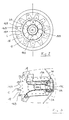
- the turbojet engine of FIG. 1 comprises a compressor 1 aspirating and compressing air so as to form at least one main flow FP of compressed air, a combustion chamber 2, a combustion chamber 3 substantially bent, at at least one means 4 for bringing a fuel into the combustion prechamber 3, at least one means 5 for supplying an oxidizer (air or gas surrounding the prechamber combustion (possibly external compressed air for example) in the combustion prechamber 3, a means 7 of the prechamber for bringing the gases of combustion of the prechamber in chamber 2, and at least one turbine 6 receiving the combustion gases from combustion chamber 2.
- the combustion chamber 2 is associated with a means 8 for receiving and directing to the at least part of the main flow of compressed air from the compressor, said means being arranged relative to the means of the prechamber bringing the gases of combustion of the prechamber in the combustion chamber so that the power and relative speed of the main compressed air flow or part of it this which is directed into the combustion chamber creates a strong suction of combustion gases from prechamber 3 and a mixture of combustion gases from prechamber with at least part of the main compressed air flow ensuring combustion of unburned fuel in the prechamber and its excess dilution of air.
- the prechamber 3 is placed in depression with respect to the combustion 2.
- the compressor comprises a rotor 10 provided with a series blades 100, and a stator 11 comprising a series of blades 110.
- the rotor 10 is extended by a shaft 12, the end of which carries a disc 14 provided with blades 15, said blades forming the blades of the turbine 6.
- the shaft 12 is put in rotation, from which the rotor 10 rotates relative to the stator 11.
- the rotation of the rotor 10 causes an air suction and compression thereof.
- the air compressed by the compressor is separated into a main flow FP and a flow secondary FS.
- This division of the compressed air leaving the compressor is obtained by the wall 16 of the prechamber facing the compressor, the crown of which outside is cut at the combustion chamber to form teeth 16A, two adjacent teeth being separated from each other by a passage 17.
- the edge of the wall 16 is extended towards the turbine 6 by a cowling or profile 18 substantially following the shape of the outer contour C of the wall and the teeth 16A.
- the wall 16 is extended by the wall 3A of the prechamber 3, which wall is turned towards the axis of rotation A-A of the turbojet, this wall having the shape of a funnel.
- Compressed air from compressor 1 passes through the central channel of the funnel in which the rotor shaft 10 extends to be brought through openings 19B and 19C of the wall 3A and of the rear wall or bottom 3B of the prechamber in the prechamber.
- the compressed air passing through the passages 17 forms the main flow FP, this main flow being guided by the outer surface of the cowling or profile 18, before to enter combustion chamber 2.
- Teeth 16A (fully open from side of the combustion chamber) form a wall of the means 7 guiding the gases combustion of the prechamber 3 towards the combustion chamber, while the face internal cover or profile 18 forms another wall of the means 7.
- the teeth 16A and / or the profile 18 have one or more openings 16B allowing air passage compressed from compressor 1 in means 7.
- This compressed air introduced into the medium 7 through the passages 16B, as well as in the orifices 19A, 19B, 19C supplies the prechamber by oxidizing and ensuring the precombustion.
- the prechamber 3 and the chamber 2 are separated from each other by a wall 19 substantially cylindrical.
- the wall 19 has a series of passages 19A allowing a gas passage from the combustion chamber 2 to the prechamber 3.
- the 19A passages are as an extension of the main air flow from passages 17.
- the means 4 for supplying the fuel into the prechamber 3 comprises a pipe 4A crossing chamber 2 and ending with an injection ramp 4B directing the fuel (vaporizable at the outlet due to the heating thereof during its passage through the pipe 4A passing through the chamber 2) towards the means 7.
- a means 5 of additional oxidizer, such as compressed air outside the compressor, for example comprises a pipe 5A passing through chamber 2 and ending with an injection ramp 5B directing the oxidant towards the means 7.
- the gases leaving chamber 2 pass through fixed guidelines 20 directing the gas flow on the blades of the turbine 6 to ensure its rotation.
- the secondary flow of compressed air does not corresponds to a fraction or part of the main flow of compressed air.
- openings 16B, 19A, 19B and 19C allow a sufficient supply of air or oxidizing in the prechamber, it is possible not to have to use means 5.
- the walls of the prechamber 3 and of the means 7 are advantageously provided in all or part of a catalytic coating ensuring better combustion.
- the turbojet engine of Figure 4 is similar to that shown in Figure 1, except that the compressor 1 comprises a totally counter-rotating stator 11 driven by a specific stage 6A (blades 30) of the turbine 6 and constituting a compressor rotor external auxiliary.
- the turbojet engine has a fixed outer casing 31 having blades interior 31A.
- the rotary stator 11 has vanes 110 on its inner face working with the blades 100 of the central rotor 10 to compress air and form the main air flows.
- the stator 11 On its outer face, the stator 11 has vanes 111 which ensures compression of an auxiliary external flow along the contour of the casing 31 of the turbojet engine.
- Combustion chamber 2 and prechamber 3 are integral with the casing 31.
- a fluid seal 32 provides a seal between a ring 33 secured to the envelopes 29 and 31 and the rotary stator 11.
- Bearings with rolling systems 34 rotate around the central axis A, rotor 10 and stator 11.
- the casing 31 is secured to arms 35 to support the combustion chamber 2, prechamber 3, as well as bearings 34.
- the stator is extended by a part forming a hollow cylinder 40 delivering passage to the shaft 12 of the rotor 10.
- the part 11 of the stator carrying the blades 110 is attached to the cylinder 40 by means of link arms 43 serving as bladders or guidelines ensuring the air passage from the compressor 1 to the chamber 2 and to the prechamber 3 by the openings 19B and 19C.
- the directors 44 integral with the casing 31 via the inner casing 29 ensures optimum direction of the gases combustion.
- the guidelines 44 are integral with a disc 45 carrying a system bearing 46.
- stator 11 can rotate in the same direction as the rotor 10, it can be advantageous to adapt the inclination of the blades 30 and the blades 15 of the turbines, to ensure that the stator is counter-rotating relative to the rotor increasing the speed relative stator-rotor blades, so as to ensure for example compression more air in compressor 1 or a reduction in the number of its necessary stages, reducing its axial size, or even reducing the mechanical stresses of rotation of the rotor and its turbine by moderating the speed rotation required.
- the invention therefore also relates to a turbojet engine type described in the first paragraph of this memo, but presenting a stator compressor of the type described for the turbojet engine of FIG. 4.
- the rotor and / or stator body of compressor 1 of the turbojets shown in Figures 1 and 4 is advantageously made by means of a layer of material thermoplastic 200 into which blades 201 are inserted in material conductive of heat, for example metal vanes which can adhere to the thermoplastic material.
- the rotor body is made of a suitable metal or alloy and is provided a layer of hot-melt material, for example a hot-melt elastomer, possibly loaded with thermoplastic material.
- a layer of hot-melt material for example a hot-melt elastomer, possibly loaded with thermoplastic material.
- the operation of pressing a blade on the layer 201 takes place once the temperature of the dawn or the end of it which has to be inserted into the hot melt layer is higher than the melting temperature of the hot-melt layer, for example 5 ° C to 50 ° C higher than the temperature of melting of the hot-melt layer, but below the carbonization temperature.
- the layer advantageously has cavities 202 or holes in the places where blades should be placed.
- These cavities 202 have advantageously a section or chamber 202A capable of receiving material in fusion when inserting the 201A end into the cavity and the part to be inserted from the body of the part.
- the cross section ST of the part 20 advantageously ballasts greater than that of the cavity ST1, while the volume of the chamber 202A advantageously corresponds to the volume V of molten material necessary for the correct insertion of the part in the layer.
- the tip 201A of the blade which is to be inserted into the layer 200 is advantageously machined to ensure a more correct positioning of the blade, in particular to avoid the formation of too large beads or to ensure a optimal evacuation of molten thermoplastic material. (figure 9).
- the part is advantageously provided with one or more holes or passages or recesses 201B in the part intended to be inserted in layer 200.
- This or these holes or passages allow to create a thermoplastic link extending through the room.
- This is particularly advantageous for flat parts to be inserted in the layer 200, for example pieces having a thickness of less than 1 cm, advantageously less than 0.5 cm.
- the room has two or more two (for example three, four, five, etc.) holes or passages in the part to insert into the thermoplastic layer.
Landscapes
- Engineering & Computer Science (AREA)
- Mechanical Engineering (AREA)
- General Engineering & Computer Science (AREA)
- Chemical & Material Sciences (AREA)
- Combustion & Propulsion (AREA)
- Chemical Kinetics & Catalysis (AREA)
- Structures Of Non-Positive Displacement Pumps (AREA)
- Turbine Rotor Nozzle Sealing (AREA)
- Engine Equipment That Uses Special Cycles (AREA)
- Separation By Low-Temperature Treatments (AREA)
Abstract
Description
La nécessaire perturbation du flux principal est requise pour assurer un mélange sensiblement homogène avec le carburant, un accrochage et un maintien de la flamme, une progression complète de la combustion, tout en assurant une température admissible pour les parois de(s) la chambre(s) et pour la (les) turbines.
De préférence, on chauffe l'extrémité de la pièce à une température de 10 à 50°C supérieure à la température de fusion de la matière thermoplastique, sans atteindre un état de carbonisation (température inférieure à la température de carbonisation ou chauffage pendant un temps très court au dessus de la température de carbonisation). De façon avantageuse, on forme préalablement dans la matière thermoplastique des cavités ou des gorges ou des trous aux endroits où une extrémité d'une aube doit être insérée. Les cavités, gorges ou trous sont de préférence adaptés pour recevoir de la matière thermoplastique ramollie ou en fusion, lors de la pénétration de l'aube dans la matière thermoplastique, et servir ainsi d'évents et/ou de moyens de positionnement de l'aube.
Par exemple, les cavités, gorges ou trous présentent une chambre adaptée pour recevoir de le matière thermoplastique ramollie ou en fusion et le restant du corps de la pièce inséré, lors de la pénétration de cette pièce dans la couche thermoplastique. Dans ce procédé, on utilise avantageusement des pièces conductrices de la chaleur ayant un point de ramollissement supérieur à la température de fusion de la couche thermoplastique. En particulier, le point de ramollissement ou de fusion de la pièce conductrice de la chaleur à insérer dans la couche thermoplastique est au moins 100°C supérieur à la température de fusion de la couche thermoplastique.
Selon une variante de ce procédé, l'extrémité de la pièce, avantageusement métallique, qui est insérée dans la couche thermoplastique est avantageusement usinée de manière à ce que cette extrémité présente une partie de moindre section que le corps de la pièce, notamment pour son chauffage ou pour son positionnement.
Claims (15)
- Turboréacteur comprenant un compresseur (1) aspirant et comprimant de l'air de manière à former au moins un flux principal (FP) d'air comprimé, une ou des chambres de combustion (2), et au moins une turbine (6) recevant les gaz de combustion de la chambre de combustion, caractérisé en ce qu'il comporte une préchambre de combustion (3) comportant un moyen ou des moyens d'amenée d'un comburant et d'un carburant (4,5), et un moyen (7) pour amener les gaz de combustion de la préchambre dans une ou des chambres de combustion, et en ce qu'il comporte un moyen (18) pour diriger au moins une partie du flux principal (FP) d'air comprimé provenant du compresseur (1) dans la, des ou les chambres de combustion, ledit moyen (18) étant agencé par rapport au moyen (7) d'amenée des gaz de combustion de la préchambre (3) dans la, des ou les chambres de combustion (2) de manière à ce qu'au moins une partie du flux principal (FP) d'air comprimé provenant du compresseur (1) dirigée dans la, des ou les chambres de combustion (2) crée une aspiration des gaz de combustion de la préchambre pour assurer dans ladite chambre de combustion (2) une combustion complémentaire, de façon avantageuse sensiblement complète, du carburant non brûlé dans la préchambre (3), cette aspiration étant avantageusement combinée avec un mélange des gaz de combustion avec une partie du flux principal (FP) d'air comprimé dans la, des ou les chambres de combustion (2).
- Turboréacteur suivant la revendication 1, caractérisé en ce que le compresseur et/ou le moyen pour diriger au moins une partie du flux principal d'air comprimé provenant du compresseur dans la chambre de combustion sont agencés pour assurer une vitesse pour la partie du flux principal introduit dans la chambre au moins supérieure à la vitesse des gaz sortant de la préchambre, de façon avantageuse au moins deux fois supérieure à la vitesse des gaz sortant de la préchambre, de préférence au moins cinq fois supérieure à la vitesse des gaz sortant de la préchambre, et pour assurer une mise en dépression de la préchambre par rapport au moins à la chambre, de préférence par rapport à la chambre et à son entourage.
- Turboréacteur selon la revendication 1, caractérisé en ce que, par rapport à la position du moyen (7) d'amenée des gaz de combustion de la préchambre (3) à la chambre de combustion (2), les moyens d'amenée de carburant et de comburant (4,5) dans la préchambre (3) sont plus proches de la turbine (6) du turboréacteur ou sont plus éloignés du compresseur (1).
- Turboréacteur selon l'une quelconque des revendications 1 à 3, caractérisé en ce qu'il présente des moyens (16A,16B,19A,19B,19C) assurant un passage d'air comprimé (FS) provenant du compresseur (1) dans la préchambre (3), lesdits moyens (16A,16B,19A,19B,19C) étant adaptés pour que le rapport flux d'air comprimé provenant du compresseur introduit dans la préchambre/flux d'air comprimé provenant du compresseur introduit dans la chambre est inférieur à 1/5, avantageusement inférieur à 1/8, de préférence inférieur à 1/10.
- Turboréacteur selon l'une des revendications 1 à 4, caractérisé en ce qu'il présente des moyens (19A) assurant un passage de gaz de la chambre (2) vers la préchambre (3), lesdits moyens (19A) étant agencés pour que des gaz de la chambre (2) entrent dans la préchambre (3) entre le moyen d'amenée de carburant (4) dans la préchambre (3) et les moyens (7), faisant avantageusement partie de la préchambre, qui amènent les gaz de combustion de la préchambre (3) dans la chambre de combustion (2) et/ou des moyens (19B,19C) assurant un passage d'air comprimé du compresseur directement vers la préchambre, en particulier vers une partie de la préchambre adjacente du moyen d'amenée de carburant.
- Turboréacteur selon l'une quelconque des revendications précédentes, caractérisé en ce que les moyens (7), faisant avantageusement partie de la préchambre, pour amener les gaz de combustion de la préchambre (3) dans la chambre de combustion (2) comportent ou forment des moyens (16, 16A, 16B, 18) divisant le flux d'air comprimé provenant du compresseur en un premier flux (FP) et en un deuxième flux (FS), ledit deuxième flux (FS) ayant un débit inférieur au premier flux (FP), et en ce qu'il comporte des moyens (16B,19B,19C) pour amener ledit deuxième flux (FS) ou une partie de celui-ci dans la préchambre (3) et/ou dans un ou des moyens (7) amenant les gaz de combustion de la préchambre (3) vers la chambre de combustion (2).
- Turboréacteur selon la revendication précédente, caractérisé en ce que le moyen (16B,19B,19C) amenant de l'air comprimé dans la préchambre (3) est adapté pour que le rapport deuxième flux (FS)/premier flux (FP) est inférieur à 1 : 5, de façon avantageuse inférieur à 1 : 8, de préférence inférieur à 1 : 10.
- Turboréacteur suivant la revendication 5 et l'une des revendications 6 et 7, caractérisé en ce que les moyens (19A) assurant un passage de gaz de la chambre (2) vers la préchambre (3) sont agencés pour ne pas être situés dans le sillage ou prolongement du flux de gaz sortant du moyen (7) guidant les gaz de la préchambre (3) dans la chambre de combustion (2).
- Turboréacteur suivant l'une quelconque des revendications précédentes, caractérisé en ce que le compresseur (1) comporte un stator (11) au moins partiellement rotatif, en particulier au moins partiellement contrarotatif par rapport au rotor (10), éventuellement solidaire d'une soufflante extérieure ou du rotor d'un compresseur auxiliaire extérieur.
- Turboréacteur suivant l'une quelconque des revendications précédentes, caractérisé en que le compresseur comporte un stator (11) muni d'aubes (110) et un rotor (10) muni d'aubes (100), le corps du rotor ou du stator comprenant une couche (200) en matière thermoplastique ou est réalisé en matière thermoplastique dans laquelle sont engagées les bases d'aubes réalisées en une matière conductrice de la chaleur.
- Turboréacteur suivant l'une quelconque des revendications précédentes, caractérisé en ce que la préchambre (3) et/ou son moyen (7) guidant les gaz de combustion de la préchambre (3) vers la chambre de combustion (2) comportent en tout ou partie au moins un revêtement contenant au moins un catalyseur de combustion.
- Procédé pour placer des aubes réalisées en matière appropriée conductrice de la chaleur sur un stator et/ou un rotor du turboréacteur de la revendication 10, ce stator et/ou rotor étant muni d'une couche en matière thermoplastique ou réalisé en matière thermoplastique, dans lequel on chauffe au moins l'extrémité de l'aube à insérer dans la matière plastique à une température supérieure à la température de ramollissement, de préférence supérieure à la température de fusion de la matière thermoplastique, et on exerce un effort de pression entre l'aube et la matière thermoplastique pour que l'extrémité de l'aube pénètre dans la matière thermoplastique.
- Procédé suivant la revendication 12, dans lequel on chauffe l'extrémité de la pièce à une température de 10 à 50°C supérieure à la température de fusion de la matière thermoplastique, mais à une température inférieure à la température de carbonisation et/ou pendant une période inférieure au temps de carbonisation.
- Procédé suivant la revendication 12 ou 13, dans lequel on forme dans la matière thermoplastique des cavités ou des gorges ou des trous aux endroits où une extrémité d'une aube doit être insérée.
- Procédé suivant la revendication 14, dans lequel les cavités, gorges ou trous sont adaptés notamment pour recevoir de la matière thermoplastique ramollie ou en fusion, lors de la pénétration de l'aube dans la matière thermoplastique.
Priority Applications (4)
| Application Number | Priority Date | Filing Date | Title |
|---|---|---|---|
| AT00870117T ATE435967T1 (de) | 2000-05-31 | 2000-05-31 | Gasturbinentriebwerk |
| EP00870117A EP1160432B1 (fr) | 2000-05-31 | 2000-05-31 | Turboréacteur |
| DE60042519T DE60042519D1 (de) | 2000-05-31 | 2000-05-31 | Gasturbinentriebwerk |
| US09/871,207 US6553765B2 (en) | 2000-05-31 | 2001-05-31 | Turbojet engine |
Applications Claiming Priority (1)
| Application Number | Priority Date | Filing Date | Title |
|---|---|---|---|
| EP00870117A EP1160432B1 (fr) | 2000-05-31 | 2000-05-31 | Turboréacteur |
Publications (2)
| Publication Number | Publication Date |
|---|---|
| EP1160432A1 true EP1160432A1 (fr) | 2001-12-05 |
| EP1160432B1 EP1160432B1 (fr) | 2009-07-08 |
Family
ID=8175757
Family Applications (1)
| Application Number | Title | Priority Date | Filing Date |
|---|---|---|---|
| EP00870117A Expired - Lifetime EP1160432B1 (fr) | 2000-05-31 | 2000-05-31 | Turboréacteur |
Country Status (4)
| Country | Link |
|---|---|
| US (1) | US6553765B2 (fr) |
| EP (1) | EP1160432B1 (fr) |
| AT (1) | ATE435967T1 (fr) |
| DE (1) | DE60042519D1 (fr) |
Families Citing this family (3)
| Publication number | Priority date | Publication date | Assignee | Title |
|---|---|---|---|---|
| WO2003008792A1 (fr) * | 2001-07-18 | 2003-01-30 | Jae-Chang Lee | Turboreacteur utilisant des gaz d'echappement |
| FR2858999B1 (fr) * | 2003-08-18 | 2005-11-11 | Snecma Moteurs | Turbomachine pour aeronef a emissions de bruit reduites |
| US8708643B2 (en) * | 2007-08-14 | 2014-04-29 | General Electric Company | Counter-rotatable fan gas turbine engine with axial flow positive displacement worm gas generator |
Citations (5)
| Publication number | Priority date | Publication date | Assignee | Title |
|---|---|---|---|---|
| GB650661A (en) | 1939-12-04 | 1951-02-28 | Rateau Soc | Jet reaction propulsion unit for aircraft |
| US3691766A (en) * | 1970-12-16 | 1972-09-19 | Rolls Royce | Combustion chambers |
| US4168609A (en) * | 1977-12-01 | 1979-09-25 | United Technologies Corporation | Folded-over pilot burner |
| US5177956A (en) * | 1991-02-06 | 1993-01-12 | Sundstrand Corporation | Ultra high altitude starting compact combustor |
| US5473881A (en) * | 1993-05-24 | 1995-12-12 | Westinghouse Electric Corporation | Low emission, fixed geometry gas turbine combustor |
Family Cites Families (2)
| Publication number | Priority date | Publication date | Assignee | Title |
|---|---|---|---|---|
| US4870824A (en) * | 1987-08-24 | 1989-10-03 | Westinghouse Electric Corp. | Passively cooled catalytic combustor for a stationary combustion turbine |
| DE4318405C2 (de) * | 1993-06-03 | 1995-11-02 | Mtu Muenchen Gmbh | Brennkammeranordnung für eine Gasturbine |
-
2000
- 2000-05-31 AT AT00870117T patent/ATE435967T1/de not_active IP Right Cessation
- 2000-05-31 EP EP00870117A patent/EP1160432B1/fr not_active Expired - Lifetime
- 2000-05-31 DE DE60042519T patent/DE60042519D1/de not_active Expired - Fee Related
-
2001
- 2001-05-31 US US09/871,207 patent/US6553765B2/en not_active Expired - Lifetime
Patent Citations (5)
| Publication number | Priority date | Publication date | Assignee | Title |
|---|---|---|---|---|
| GB650661A (en) | 1939-12-04 | 1951-02-28 | Rateau Soc | Jet reaction propulsion unit for aircraft |
| US3691766A (en) * | 1970-12-16 | 1972-09-19 | Rolls Royce | Combustion chambers |
| US4168609A (en) * | 1977-12-01 | 1979-09-25 | United Technologies Corporation | Folded-over pilot burner |
| US5177956A (en) * | 1991-02-06 | 1993-01-12 | Sundstrand Corporation | Ultra high altitude starting compact combustor |
| US5473881A (en) * | 1993-05-24 | 1995-12-12 | Westinghouse Electric Corporation | Low emission, fixed geometry gas turbine combustor |
Also Published As
| Publication number | Publication date |
|---|---|
| ATE435967T1 (de) | 2009-07-15 |
| DE60042519D1 (de) | 2009-08-20 |
| US6553765B2 (en) | 2003-04-29 |
| EP1160432B1 (fr) | 2009-07-08 |
| US20020026787A1 (en) | 2002-03-07 |
Similar Documents
| Publication | Publication Date | Title |
|---|---|---|
| EP4072943B1 (fr) | Systeme de propulsion pour un aeronef, ledit systeme de propulsion comportant une pile a combustible | |
| EP2880285B1 (fr) | Rampe d'injection modulaire a double circuit | |
| EP2478198B1 (fr) | Turbomoteur a arbres paralleles | |
| EP0604279B1 (fr) | Injecteur avec paroi poreuse pour chambre de combustion d'une fusée | |
| FR2915521A1 (fr) | Generateur de tourbillons d'ecoulement de fluide caloporteur pour un moteur-fusee | |
| FR2541371A1 (fr) | Circuit de refroidissement pour moteur a turbine a gaz | |
| FR2967725A1 (fr) | Propulseur combine turboreacteur et statoreacteur | |
| CA2929798A1 (fr) | Enceinte avant etanche lors du desassemblage modulaire d'un turboreacteur a reducteur | |
| EP3545176B1 (fr) | Turbomachine, notamment turbogenerateur et echangeur pour une telle turbomachine | |
| EP0323299A1 (fr) | Appareil destiné à assurer la combustion étagée d'un mélange combustible-comburant diminuant la production d'oxydes d'azote | |
| FR2602309A1 (fr) | Buse de coupe siderurgique a double couronne de chauffe | |
| EP0499535B1 (fr) | Chambre de combustion pour turboréacteur à faible niveau d'émissions polluantes | |
| CA2605947C (fr) | Canal de transition entre deux etages de turbine | |
| CA2494433C (fr) | Bras monobloc accroche-flammes pour un dispositif de post-combustion d`un turboreacteur a double flux | |
| EP3156635A1 (fr) | Moteur fusée à torche d'allumage versatile | |
| EP0031770B1 (fr) | Perfectionnements apportés aux moteurs à combustion interne suralimentés, notamment aux moteurs Diesel | |
| EP1553282A1 (fr) | Dispositif d'alimentation en air de refroidissement de volets de tuyère | |
| EP1342904B1 (fr) | Chambre de combustion pour statoréacteur et statoréacteur pourvu d'une telle chambre de combustion | |
| EP2748532A1 (fr) | Paroi de chambre de combustion | |
| EP1160432B1 (fr) | Turboréacteur | |
| EP2078822B1 (fr) | Moteur à turbine à gaz avec clapet de mise en communication de deux enceintes | |
| EP3688294B1 (fr) | Chambre de combustion à volume constant et système de combustion pour turbomachine associé | |
| FR2712962A1 (fr) | Dispositif de postcombustion comprenant un dispositif accroche-flammes perfectionné. | |
| FR3115066A1 (fr) | Moteur à combustion interne et procédé de fonctionnement d'un moteur à combustion interne | |
| FR2880381A1 (fr) | Turbomachine a aubes |
Legal Events
| Date | Code | Title | Description |
|---|---|---|---|
| PUAI | Public reference made under article 153(3) epc to a published international application that has entered the european phase |
Free format text: ORIGINAL CODE: 0009012 |
|
| AK | Designated contracting states |
Kind code of ref document: A1 Designated state(s): AT BE CH CY DE DK ES FI FR GB GR IE IT LI LU MC NL PT SE |
|
| AX | Request for extension of the european patent |
Free format text: AL;LT;LV;MK;RO;SI |
|
| 17P | Request for examination filed |
Effective date: 20020525 |
|
| AKX | Designation fees paid |
Free format text: AT BE CH CY DE DK ES FI FR GB GR IE IT LI LU MC NL PT SE |
|
| 17Q | First examination report despatched |
Effective date: 20061127 |
|
| GRAP | Despatch of communication of intention to grant a patent |
Free format text: ORIGINAL CODE: EPIDOSNIGR1 |
|
| GRAS | Grant fee paid |
Free format text: ORIGINAL CODE: EPIDOSNIGR3 |
|
| GRAA | (expected) grant |
Free format text: ORIGINAL CODE: 0009210 |
|
| AK | Designated contracting states |
Kind code of ref document: B1 Designated state(s): AT BE CH CY DE DK ES FI FR GB GR IE IT LI LU MC NL PT SE |
|
| REG | Reference to a national code |
Ref country code: GB Ref legal event code: FG4D Free format text: NOT ENGLISH |
|
| REG | Reference to a national code |
Ref country code: CH Ref legal event code: EP |
|
| REG | Reference to a national code |
Ref country code: IE Ref legal event code: FG4D |
|
| REF | Corresponds to: |
Ref document number: 60042519 Country of ref document: DE Date of ref document: 20090820 Kind code of ref document: P |
|
| NLV1 | Nl: lapsed or annulled due to failure to fulfill the requirements of art. 29p and 29m of the patents act | ||
| PG25 | Lapsed in a contracting state [announced via postgrant information from national office to epo] |
Ref country code: AT Free format text: LAPSE BECAUSE OF FAILURE TO SUBMIT A TRANSLATION OF THE DESCRIPTION OR TO PAY THE FEE WITHIN THE PRESCRIBED TIME-LIMIT Effective date: 20090708 Ref country code: ES Free format text: LAPSE BECAUSE OF FAILURE TO SUBMIT A TRANSLATION OF THE DESCRIPTION OR TO PAY THE FEE WITHIN THE PRESCRIBED TIME-LIMIT Effective date: 20091019 Ref country code: FI Free format text: LAPSE BECAUSE OF FAILURE TO SUBMIT A TRANSLATION OF THE DESCRIPTION OR TO PAY THE FEE WITHIN THE PRESCRIBED TIME-LIMIT Effective date: 20090708 |
|
| REG | Reference to a national code |
Ref country code: IE Ref legal event code: FD4D |
|
| PG25 | Lapsed in a contracting state [announced via postgrant information from national office to epo] |
Ref country code: NL Free format text: LAPSE BECAUSE OF FAILURE TO SUBMIT A TRANSLATION OF THE DESCRIPTION OR TO PAY THE FEE WITHIN THE PRESCRIBED TIME-LIMIT Effective date: 20090708 |
|
| PG25 | Lapsed in a contracting state [announced via postgrant information from national office to epo] |
Ref country code: PT Free format text: LAPSE BECAUSE OF FAILURE TO SUBMIT A TRANSLATION OF THE DESCRIPTION OR TO PAY THE FEE WITHIN THE PRESCRIBED TIME-LIMIT Effective date: 20091109 |
|
| PG25 | Lapsed in a contracting state [announced via postgrant information from national office to epo] |
Ref country code: IE Free format text: LAPSE BECAUSE OF FAILURE TO SUBMIT A TRANSLATION OF THE DESCRIPTION OR TO PAY THE FEE WITHIN THE PRESCRIBED TIME-LIMIT Effective date: 20090708 Ref country code: DK Free format text: LAPSE BECAUSE OF FAILURE TO SUBMIT A TRANSLATION OF THE DESCRIPTION OR TO PAY THE FEE WITHIN THE PRESCRIBED TIME-LIMIT Effective date: 20090708 |
|
| PLBE | No opposition filed within time limit |
Free format text: ORIGINAL CODE: 0009261 |
|
| STAA | Information on the status of an ep patent application or granted ep patent |
Free format text: STATUS: NO OPPOSITION FILED WITHIN TIME LIMIT |
|
| 26N | No opposition filed |
Effective date: 20100409 |
|
| PG25 | Lapsed in a contracting state [announced via postgrant information from national office to epo] |
Ref country code: GR Free format text: LAPSE BECAUSE OF FAILURE TO SUBMIT A TRANSLATION OF THE DESCRIPTION OR TO PAY THE FEE WITHIN THE PRESCRIBED TIME-LIMIT Effective date: 20091009 |
|
| BERE | Be: lapsed |
Owner name: BREGENTZER, DANIEL Effective date: 20100531 |
|
| PG25 | Lapsed in a contracting state [announced via postgrant information from national office to epo] |
Ref country code: MC Free format text: LAPSE BECAUSE OF NON-PAYMENT OF DUE FEES Effective date: 20100531 |
|
| REG | Reference to a national code |
Ref country code: CH Ref legal event code: PL |
|
| PG25 | Lapsed in a contracting state [announced via postgrant information from national office to epo] |
Ref country code: LI Free format text: LAPSE BECAUSE OF NON-PAYMENT OF DUE FEES Effective date: 20100531 Ref country code: CH Free format text: LAPSE BECAUSE OF NON-PAYMENT OF DUE FEES Effective date: 20100531 |
|
| PG25 | Lapsed in a contracting state [announced via postgrant information from national office to epo] |
Ref country code: IT Free format text: LAPSE BECAUSE OF FAILURE TO SUBMIT A TRANSLATION OF THE DESCRIPTION OR TO PAY THE FEE WITHIN THE PRESCRIBED TIME-LIMIT Effective date: 20090708 Ref country code: BE Free format text: LAPSE BECAUSE OF NON-PAYMENT OF DUE FEES Effective date: 20100531 |
|
| PG25 | Lapsed in a contracting state [announced via postgrant information from national office to epo] |
Ref country code: DE Free format text: LAPSE BECAUSE OF NON-PAYMENT OF DUE FEES Effective date: 20101201 |
|
| PG25 | Lapsed in a contracting state [announced via postgrant information from national office to epo] |
Ref country code: CY Free format text: LAPSE BECAUSE OF FAILURE TO SUBMIT A TRANSLATION OF THE DESCRIPTION OR TO PAY THE FEE WITHIN THE PRESCRIBED TIME-LIMIT Effective date: 20090708 |
|
| PG25 | Lapsed in a contracting state [announced via postgrant information from national office to epo] |
Ref country code: SE Free format text: LAPSE BECAUSE OF FAILURE TO SUBMIT A TRANSLATION OF THE DESCRIPTION OR TO PAY THE FEE WITHIN THE PRESCRIBED TIME-LIMIT Effective date: 20090708 Ref country code: LU Free format text: LAPSE BECAUSE OF NON-PAYMENT OF DUE FEES Effective date: 20100531 |
|
| PGFP | Annual fee paid to national office [announced via postgrant information from national office to epo] |
Ref country code: FR Payment date: 20130603 Year of fee payment: 14 |
|
| REG | Reference to a national code |
Ref country code: FR Ref legal event code: ST Effective date: 20150130 |
|
| PG25 | Lapsed in a contracting state [announced via postgrant information from national office to epo] |
Ref country code: FR Free format text: LAPSE BECAUSE OF NON-PAYMENT OF DUE FEES Effective date: 20140602 |
|
| PGFP | Annual fee paid to national office [announced via postgrant information from national office to epo] |
Ref country code: GB Payment date: 20150623 Year of fee payment: 16 |
|
| GBPC | Gb: european patent ceased through non-payment of renewal fee |
Effective date: 20160531 |
|
| PG25 | Lapsed in a contracting state [announced via postgrant information from national office to epo] |
Ref country code: GB Free format text: LAPSE BECAUSE OF NON-PAYMENT OF DUE FEES Effective date: 20160531 |