EP1160377A2 - Drying section with a coated drying cylinder - Google Patents
Drying section with a coated drying cylinder Download PDFInfo
- Publication number
- EP1160377A2 EP1160377A2 EP01660105A EP01660105A EP1160377A2 EP 1160377 A2 EP1160377 A2 EP 1160377A2 EP 01660105 A EP01660105 A EP 01660105A EP 01660105 A EP01660105 A EP 01660105A EP 1160377 A2 EP1160377 A2 EP 1160377A2
- Authority
- EP
- European Patent Office
- Prior art keywords
- web
- drying
- coating
- ceramic
- metal
- Prior art date
- Legal status (The legal status is an assumption and is not a legal conclusion. Google has not performed a legal analysis and makes no representation as to the accuracy of the status listed.)
- Withdrawn
Links
Images


Classifications
-
- D—TEXTILES; PAPER
- D21—PAPER-MAKING; PRODUCTION OF CELLULOSE
- D21F—PAPER-MAKING MACHINES; METHODS OF PRODUCING PAPER THEREON
- D21F5/00—Dryer section of machines for making continuous webs of paper
- D21F5/02—Drying on cylinders
- D21F5/021—Construction of the cylinders
-
- D—TEXTILES; PAPER
- D21—PAPER-MAKING; PRODUCTION OF CELLULOSE
- D21F—PAPER-MAKING MACHINES; METHODS OF PRODUCING PAPER THEREON
- D21F5/00—Dryer section of machines for making continuous webs of paper
- D21F5/02—Drying on cylinders
- D21F5/04—Drying on cylinders on two or more drying cylinders
Definitions
- the present invention relates to paper machines. More specifically, the present invention relates to an arrangement for improving the beginning of the drying section joined to the closed web transfer following the press section of the paper machine, in which paper machine: moisture is removed from the web in the press section; and the web is transferred from the press section to a first bank of drying cylinders, in which drying section the web will dry against the heated drying cylinder surfaces essentially to a coating or calendering moisture content.
- the web transfer from the press section to the drying section is typically either open or closed, and the drying cylinders are typically cast iron or steel cylinders.
- An open web transfer means that the web travels freely from the press section to the drying section, that is, without any support from a supporting means, such as typically a transfer belt or felt.
- a drying wire is guided against the web and the web is transferred together with the drying wire and comes into contact with the surface of a drying cylinder made of cast iron or steel.
- the advantage of open web transfer is that there is hardly any working up or formation of fluff on the web surface, whereby following the drying wire the web will separate relatively easily from the drying cylinder surface and no essential runability problems will occur.
- it is a problem with open web transfer that the web receives all the tensile stress.
- Loose material or fibre fluff or bundles may also separate more easily from a web adhering more strongly to the drying cylinder surface, and these will adhere to the drying cylinder surface, from which they must be removed before the drying cylinder again rotates against the web, and the web separates less easily from the drying cylinder surface.
- various doctor solutions are used which contact the drying cylinder surface. But it is a common problem with doctors that loose material gathering behind and under the doctor will bypass the doctor and get in contact with the web, whereby loose material will adhere to the web, which adds essentially to the quality problems.
- Closed web transfer in the press section and from the press section to the drying section means that in the press section the web travels all the time supported by a supporting means located above and/or under the web.
- a supporting means typically a transfer belt or felt, on the upper or bottom side of which the web is supported and it is transferred forward from the press section.
- the web is separated from the supporting means before the drying cylinder with the aid of a suction roll, whereby an endless supporting means loop travels around the leading roll and the web is pressed against the drying wire travelling around the suction roll and it transfers together with the drying wire to get in contact with the drying cylinder surface.
- a first objective of the present invention is to eliminate or at least to reduce the problems relating to the known web transfer and to bring about a new and inventive arrangement for web transfer in a paper machine after the press section.
- a special objective of the present invention, along with a new and inventive arrangement, is to:
- the invention is based on the new and inventive basic idea that in order to achieve less fouling, that is, formation of fluff, on the drying cylinder, to improve separation of the web from the drying cylinder surface, to achieve easier doctoring of the drying cylinder surface and a better doctoring tolerance, the surface of at least the first drying cylinder in the drying cylinder bank is surface-coated or coated with a thin, preferably hard coating, to which the web attaches weakly, or the drying cylinder surface has absorbed a material, to which the web will attach weakly.
- the supporting means of the web will receive entirely or at least partly the tensile stress applied to the web; the web will separate essentially without effort together with the drying wire from the drying cylinder surface; less loose material or fibre fluff or fibre bundles will separate from the web on to the drying cylinder surface; and less cleaning is needed with a doctor stressing the drying cylinder surface.
- a coating which is chosen so that adherence of the web to the drying cylinder surface is made as weak as possible, is a ceramic material or metal ceramic or a mixture or compound of these.
- the coating may also be a mixture of the above-mentioned ceramic materials or of metal ceramics and a metal.
- Such a ceramic material or metal ceramic coating the thickness of which is preferably in a range between 0.03 and 6 mm, can be sprayed thermally on to the roll surface, and in order to ensure adhesion a thin adhesive layer may be used between the coating and the coat iron or steel surface of the cylinder.
- the porous drying cylinder surface may be covered or coated with fluorated plastic or with fluorated epoxy, which has the same properties as fluoroplastic, either alone or in addition to the above-mentioned coating.
- Figure 1 is a schematic view of the press section 1 in a paper machine, wherein water is pressed out of web W and wherein a closed web transfer is arranged for web W through the press section 1 to the drying section 3.
- web W is dried to a solids content required by the web treatment after the drying section, such as e.g. coating or calendering or reeling etc.
- web W travels through press rolls 14 and 15 in between a press felt 10 and a transfer means 4.
- the press felt 10 is illustrated by a line of dots and dashes and the endless loop which it forms travels around the leading rolls 12 of the press felt 10.
- the transfer means 4 is preferably a transfer belt impervious to liquid and/or air, but it may also be a press felt or equivalent, and in Figure 1 it is illustrated by a dashed line. Transfer belt 4 forms an endless loop, which travels around leading rolls 13. After press rolls 14 and 15, press felt 10 is separated from web W, whereupon the web is held on to transfer means 4, which supports it.
- press section 1 the web proceeds in closed web transfer on the transfer means 4 to the drying unit 3.
- the press unit 1 In the travelling direction of the web, that is, in the MD direction of the paper machine, the press unit 1 is followed by a suction roll 5, around which a drying wire 8 is turning. Suction affecting in the suction zone of suction roll 5 forces the web W against the drying wire 8, which in Figure 1 is illustrated by a dotted line, and along with this to a first drying cylinder 6 1 .
- the suction roll 5 is followed, preferably immediately, by the leading roll 13 of the transfer means 4, and the leading roll is used to guide the travel of transfer means 4 away from the bottom surface of web W.
- web W travels supported against the bottom surface of drying wire 8 to the first bank of drying cylinders of drying unit 3 and into direct contact with the heated cylinder surface of the first drying cylinder 6 1 .
- web W turns around hitch roll 7, whereby drying wire 8 is against the cylinder surface of the hitch roll and web W is outside drying wire 8, to the second drying cylinder 6 2 of the first bank of drying cylinders.
- the endless drying wire loop revolving in the first bank of drying cylinders in the drying section travels both by way of the leading rolls 41 of drying wire 8 and also around suction roll 5, the first drying cylinder 6 1 and the first hitch roll 7, and after the first drying cylinder-hitch roll pair 6 1 , 7 it zigzags around the following drying cylinder-hitch roll pairs 6 n , 7.
- the surface of at least the first drying cylinder 6 1 of the drying cylinder bank is surface-coated or coated with a thin, preferably hard coating 60.
- a coating 60 to which the web will adhere weakly, is absorbed into the surface of the drying cylinder 6 1-n made alternatively or optionally of cast iron or with a surface of some other material or with a hard-coated surface.
- the absorption material 60 hereby need not cover the metal surface of the drying cylinder 6 1-n uniformly and everywhere.
- the surface-coating or coating or absorption material 60 is chosen so that web W will adhere weakly to the surface-coating or coating or absorption material 60.
- web W separates together with drying wire 8 essentially effortlessly from the surface of drying cylinder 6 1-n and less loose material or fibre fluff or fibre bundles will separate from web W on to the surface of drying cylinder 6 1-n , which again reduces the cleaning work to be done on the surface of drying cylinder 6 1-n with a doctor 9 1a and with a secondary doctor 9 1b .
- the first possible place where the entire web W can be run in a controlled fashion down into pulper 31, is the first drying cylinder 6 1 after suction roll 5.
- Figure 1 shows in connection with the first drying cylinder two successive doctors 9 1a , 9 1b to ensure that all loose material or the leader or the whole web is safely separated from the surface of drying cylinder 6 1 and guided into the pulper 31 located below.
- the surface-coating in accordance with the invention is arranged in the drying unit in the first drying cylinder 61 of at least the first bank of drying cylinders. It should be emphasised, that in order to minimise adherence and to minimise the need for doctoring, the surface-coating or coating of the surface or absorption of the surface according to the invention may also be arranged in the following drying cylinders 6 2- n . Hereby it is possible to reduce the cleaning work stressing the surface of drying cylinders 6 2-n , which is to be performed in the whole drying unit by all doctors 9 2-n .
- Another noteworthy advantage is achieved in that loose material or fibre fluff or fibre bundles separate less than before in connection with the cleaning work, whereby less loose material of all kinds is gathered in pulper 31 as a result of the doctoring work.
- the work to overcome friction resistance is also reduced, which reduces the drying section's need for rotating power, which may form a restricting factor in existing machines with increasing speeds of rotation.
- tension variations in webs are reduced in web-driven systems.
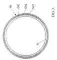
- FIG. 3 is a schematic cross-sectional view of the drying cylinder 6 1 according to the invention.
- the coating 60 according to an advantageous embodiment of the invention of drying cylinder 6 1 includes or the coating 60 consists of a hard layer 602 of a ceramic material, which is preferably oxide ceramic, such as Zr, Al, Si, Ti, Y, Cr oxide ceramics, or carbide ceramic, such as Cr, W, Ti, Ni carbide ceramics.
- the hard layer 602 may also consist of a mixture or compound of the above-mentioned ceramic materials.
- the hard layer 602 of coating 60 may according to the invention also be a mixture or compound of the above-mentioned ceramic materials and a metal, preferably chrome, nickel and/or molybdenum. Such mixtures and compounds are generally known by the name of metal ceramics or cerametals or cermet.
- the hard layer 602 of coating 60 may be made not only of a ceramic material or metal ceramics, but also of a metal, which preferably is chrome, molybdenum and/or nickel,
- the thickness of the ceramic material or metal ceramics coating 60 forming the hard layer 602 of coating 60 is preferably in a range of 0.03-6 mm, most preferably in a range of 0.05-2 mm.
- Such a coating 60 can be spread out by plasma spraying or by HVOF (High Velocity Oxy Fuel) spraying thermally on to the roll surface, whereby a surface of ceramic material or metal ceramics is formed.
- a thin adhesive layer 601 may be used, which is e.g. a non-porous metal layer, which thus does not have any essential effect on the total thermal conductivity of the drying cylinder and which functions as a protective layer against corrosion at the same time.
- fluorated plastic preferably PTFE (Polytetrafluoroethylene, a known trademark of which is TEFLON®), or fluorated epoxy with the same properties as PTFE
- PTFE Polytetrafluoroethylene, a known trademark of which is TEFLON®
- fluorated epoxy with the same properties as PTFE
- the cast iron or steel surface of the drying cylinder is first surface-coated with the above-mentioned hard coating 602, which is made to adhere to the drying cylinder surface by an adhesive layer 601. Because the hard coating 602 leaves the outer surface porous, fluorated plastic or fluorated epoxy may be absorbed into the pores of the hard surface.
- the coating 60 When fluorated plastic or fluorated epoxy is also absorbed into the coating 60 of the drying cylinder including a hard layer 602, the coating 60 according to the most preferable embodiment of the invention consists of a PTFE coated ceramic material or of PTFE coated metal ceramics.
- the cylinder may also be surface-coated by coating the cylinder surface with fluorated plastic, which is preferably PTFE, with a coated metal layer, wherein the metal is preferably nickel, chrome or molybdenum.
- fluorated plastic which is preferably PTFE
- a coated metal layer wherein the metal is preferably nickel, chrome or molybdenum.
- the coating is a PTFE coated metal.
- Figure 2 is a graphic view of the paper web's separation force from different drying cylinder surfaces as a function of the separation angle based on test runs carried out at a production velocity of 22 m/s.
- the most essential coatings are the following, besides metal coatings:
- Figure 2 illustrates the separation force of the paper web from surfaces, which are:
- Figure 2 illustrates for the sake of comparison the separation force of the paper web from a cylinder surface made of cast iron or steel at a corresponding production velocity.
- the press section and drying section shown in Figure 1 it is possible to arrange one or more desired units, e.g. a web transfer and/or pre-drying unit, on to which the web is taken from the press section as closed web transfer and from which the web is taken further as closed web transfer to the drying section, the first drying cylinder of which is a coated drying cylinder in accordance with the invention.
- desired units e.g. a web transfer and/or pre-drying unit
Landscapes
- Paper (AREA)
- Drying Of Solid Materials (AREA)
Abstract
Description
- reduce fouling, that is, formation of fluff, on the drying cylinder,
- improve separation of the web from the drying cylinder surface,
- facilitate doctoring of the drying cylinder surface, and
- reduce wear of both the doctor touching the drying cylinder and of the drying cylinder and to improve the doctoring tolerance of both the drying cylinder and the doctor blade,
i. a metallic material or a metal alloy
ii. a ceramic material, such as oxide or carbide ceramic, or a mixture or compound of ceramic materials
iii. a ceramic formed by oxidisation, usually a metal oxide
iv. a carbide usually formed by carbon and a metal
v. a mixture or compound of a ceramic material and a metal
Claims (13)
- Arrangement for improving the beginning of the drying section (3) joined to closed web transfer after the press section (1) in a paper machine, in which paper machine: moisture is removed from the web (W) in the press section (1); and the web is guided from the press section to the first bank of drying cylinders of the drying section (3), in which drying section (3) the web dries against heated drying cylinder surfaces essentially to the solids content required for treatment of the web after the drying section (3), such as e.g. coating or calendering or reeling or other such, characterised in that in order to achieve less fouling of the drying cylinder (61-n), that is, less fluff formation, to achieve better doctorability and better doctoring tolerance of the drying cylinder (61-n) surface in the drying section (3) there is a coating (60) on the surface of at least the first drying cylinder (61), which coating includes a thin, preferably hard layer (602) of ceramic material and/or metal ceramic and/or metal, to which the web will adhere weakly, and/or another softer material (603), to which the web will adhere weakly is absorbed into the drying cylinder (61-n) surface, whereby separation of the web (W) from the surface of the drying cylinder (61-n) is improved.
- Arrangement as defined in claim 1, characterised in that at least the first two drying cylinders (61-n) of the drying section (3) include a thin preferably hard coating layer (60) of a ceramic material and/or metal ceramic and/or metal.
- Arrangement as defined in claim 1 and/or 2, characterised in that fluorated plastic or fluorated epoxy (603) is absorbed into the surface of the drying cylinder (61...n).
- Arrangement as defined in claim 3, characterised in that the fluorated plastic is polytetrafluoroethylene.
- Arrangement as defined in claim 1 and/or 2, characterised in that the coating (60) of the drying cylinder (61...n) made of cast iron or steel includes a lower hard layer (602), which is of a ceramic material, metal ceramic and/or metal, and a softer layer (603) of fluorated plastic or epoxy of the kind absorbed into the hard layer (602).
- Arrangement as defined in claim 1 and/or 2, characterised in that the coating (60) consists of a hard layer (602) only, which is ceramic material, metal ceramic and/or metal.
- Arrangement as defined in any one of claims 1-6, characterised in that the ceramic material (602) forming the hard layer (602) of the coating (60) is oxide ceramic, preferably Zr, Al, Si, Ti, Y or Cr oxide ceramic, and/or carbide ceramic, preferably Cr, W, Ti or Ni carbide ceramic.
- Arrangement as defined in any one of claims 1-6, characterised in that the metal ceramic forming the hard layer (602) of the coating (60) is a mixture or compound of an oxide ceramic, which is preferably Zr, Al, Si, Ti, Y or Cr oxide ceramic, and/or a carbide ceramic, which is preferably Cr, W, Ti or Ni carbide ceramic, and a metal, which is preferably Cr, Ni or Mo.
- Arrangement as defined in any one of claims 1-6, characterised in that the metal forming the hard layer (602) of the coating (60) is preferably Cr, Ni or Mo.
- Arrangement as defined in any one of claims 1-6, characterised in that the lower hard layer (602) of the coating (60) is a mixture or compound of at least two materials, which materials have been chosen from a set including:and that a softer layer (603) of fluorated plastic, such as PTFE, and/or fluorated epoxy, is absorbed into the surface of the hard layer (602).oxide ceramics, preferably Zr, Al, Si, Ti, Y and Cr oxide ceramics,carbide ceramics, preferably Cr, W, Ti and Ni carbide ceramics,metal ceramics, preferably Zr, Al, Si, Ti, Y and Cr oxide ceramics, and/or mixtures or compounds of Cr, W, Ti or Ni carbide ceramics and metals, preferably Cr, Ni or Mo, andmetals, preferably Ni, Cr and Mo,
- Arrangement as defined in any one of claims 1-10, characterised in that the thickness of the hard layer (602) of a ceramic material and/or a metal ceramic in the coating (60) is preferably in a range of 0.03-6 mm, most preferably in a range of 0.05-2 mm.
- Arrangement as defined in any one of claims 1-11, characterised in that the hard layer (602) of the coating (60) is sprayed thermally on to the surface of the drying cylinder (61-n) and that to ensure adhesion an adhesive layer (601), which is preferably a non-porous metal layer, is used in between the hard layer (602) of the coating (60) and the cast iron or steel cylinder surface of the drying cylinder (61, 62, 6n).
- Arrangement as defined in any one of claims 1-12, characterised in that fluorated plastic is absorbed into the coating (6) including the hard layer (602), whereby the coating (60) consists of a PTFE coated ceramic material or of a PTFE coated metal ceramic or of a PTFE coated metal.
Applications Claiming Priority (4)
| Application Number | Priority Date | Filing Date | Title |
|---|---|---|---|
| FI20001332A FI20001332A0 (en) | 2000-06-02 | 2000-06-02 | Arrangements for improving the beginning of the drying section connecting to the web guide between the pressing portion and the drying portion of a paper machine |
| FI20001332 | 2000-06-02 | ||
| FI20002122 | 2000-09-27 | ||
| FI20002122A FI20002122L (en) | 2000-06-02 | 2000-09-27 | Arrangement for improving the start of the drying section of a paper machine |
Publications (2)
| Publication Number | Publication Date |
|---|---|
| EP1160377A2 true EP1160377A2 (en) | 2001-12-05 |
| EP1160377A3 EP1160377A3 (en) | 2002-06-12 |
Family
ID=26161019
Family Applications (1)
| Application Number | Title | Priority Date | Filing Date |
|---|---|---|---|
| EP01660105A Withdrawn EP1160377A3 (en) | 2000-06-02 | 2001-05-29 | Drying section with a coated drying cylinder |
Country Status (3)
| Country | Link |
|---|---|
| US (1) | US20020060023A1 (en) |
| EP (1) | EP1160377A3 (en) |
| FI (1) | FI20002122L (en) |
Cited By (6)
| Publication number | Priority date | Publication date | Assignee | Title |
|---|---|---|---|---|
| EP1382739A1 (en) * | 2002-07-19 | 2004-01-21 | Mitsubishi Heavy Industries, Ltd. | Drive control in a paper machine |
| WO2006072505A1 (en) * | 2005-01-05 | 2006-07-13 | Voith Patent Gmbh | Device and method for producing and/or transforming a web of fibrous material |
| EP1698727A1 (en) * | 2005-03-04 | 2006-09-06 | Voith Paper Patent GmbH | Paper machine |
| CN103842586A (en) * | 2011-07-06 | 2014-06-04 | 沃依特专利有限责任公司 | Removal-force-profiled drying cylinder |
| CN107407052A (en) * | 2015-03-12 | 2017-11-28 | 亚赛利纸业设备有限公司 | The controllable Yankee dryer of thermal expansion |
| WO2020035318A1 (en) * | 2018-08-14 | 2020-02-20 | Voith Patent Gmbh | Paper machine and method for producing a paper or paperboard web |
Families Citing this family (5)
| Publication number | Priority date | Publication date | Assignee | Title |
|---|---|---|---|---|
| DE102005000782A1 (en) | 2005-01-05 | 2006-07-20 | Voith Paper Patent Gmbh | Drying cylinder for use in the production or finishing of fibrous webs, e.g. paper, comprises heating fluid channels between a supporting structure and a thin outer casing |
| US9428861B2 (en) * | 2011-12-14 | 2016-08-30 | Voith Patent Gmbh | Device for manufacturing a material web |
| ITFI20130241A1 (en) * | 2013-10-15 | 2015-04-16 | Celli Paper S P A A | "PLANT COMPONENTS FOR THE PRODUCTION OF DAMP PAPER" |
| CN106930135B (en) * | 2017-03-09 | 2018-05-04 | 松阳县晨丰纸业有限公司 | A kind of not viscous Drying processing technology of food-grade filter paper dedicated drying machine |
| CN107191472B (en) * | 2017-05-17 | 2019-04-19 | 安徽巨泰机械制造有限公司 | A kind of agricultural machinery high-strength wearable idler wheel |
Family Cites Families (4)
| Publication number | Priority date | Publication date | Assignee | Title |
|---|---|---|---|---|
| US5272821A (en) * | 1989-10-15 | 1993-12-28 | Institute Of Paper Science And Technology, Inc. | Method and apparatus for drying web |
| FI98387C (en) * | 1995-02-01 | 1997-06-10 | Valmet Corp | Process for making surface-treated paper, especially fine paper, and dry end for a paper machine |
| FI950849A7 (en) * | 1995-02-24 | 1996-08-25 | Valmet Corp | Method for controlling the surface properties of paper machine surfaces and use of the method for surface treatment of paper machine surfaces |
| US6049998A (en) * | 1997-11-10 | 2000-04-18 | Beloit Technologies Inc. | Apparatus and method for high temperature pressing followed by high intensity drying |
-
2000
- 2000-09-27 FI FI20002122A patent/FI20002122L/en unknown
-
2001
- 2001-05-29 EP EP01660105A patent/EP1160377A3/en not_active Withdrawn
- 2001-05-30 US US09/870,192 patent/US20020060023A1/en not_active Abandoned
Cited By (6)
| Publication number | Priority date | Publication date | Assignee | Title |
|---|---|---|---|---|
| EP1382739A1 (en) * | 2002-07-19 | 2004-01-21 | Mitsubishi Heavy Industries, Ltd. | Drive control in a paper machine |
| WO2006072505A1 (en) * | 2005-01-05 | 2006-07-13 | Voith Patent Gmbh | Device and method for producing and/or transforming a web of fibrous material |
| EP1698727A1 (en) * | 2005-03-04 | 2006-09-06 | Voith Paper Patent GmbH | Paper machine |
| CN103842586A (en) * | 2011-07-06 | 2014-06-04 | 沃依特专利有限责任公司 | Removal-force-profiled drying cylinder |
| CN107407052A (en) * | 2015-03-12 | 2017-11-28 | 亚赛利纸业设备有限公司 | The controllable Yankee dryer of thermal expansion |
| WO2020035318A1 (en) * | 2018-08-14 | 2020-02-20 | Voith Patent Gmbh | Paper machine and method for producing a paper or paperboard web |
Also Published As
| Publication number | Publication date |
|---|---|
| US20020060023A1 (en) | 2002-05-23 |
| FI20002122A0 (en) | 2000-09-27 |
| FI20002122A7 (en) | 2001-12-03 |
| FI20002122L (en) | 2001-12-03 |
| EP1160377A3 (en) | 2002-06-12 |
Similar Documents
| Publication | Publication Date | Title |
|---|---|---|
| CA2167856C (en) | Method for producing surface-treated paper and dry end of a paper machine | |
| US20020060023A1 (en) | Arrangement for improving the beginning of the drying section | |
| JP4644372B2 (en) | Paper web or cardboard web processing method and processing apparatus | |
| SE531891C2 (en) | Structural lining and method for making a tissue paper web | |
| EP2072673B1 (en) | Belt assembly and paper- or board making machine comprising the belt assembly | |
| JP3764049B2 (en) | Use of transfer belts for soft tissue paper machines | |
| JPH11500792A (en) | Method and apparatus for removing water from paper or paperboard web by pressing | |
| CA2165974A1 (en) | Process and device for producing paper webs coated on both sides | |
| EP1285127B1 (en) | Method for calendering a board web | |
| FI111976B (en) | Method and apparatus for producing paper webs coated on each side | |
| EP0820546B1 (en) | Method in film transfer coating and equipment intended for carrying out the method | |
| CA1121196A (en) | Procedure and apparatus for separating the web from the former wire and for transferring it to a fabric belonging to the press section | |
| JP3802933B2 (en) | Application of thermal barrier coating to paper machine drying cylinder to prevent over-drying of paper edge | |
| FI104434B (en) | Drying batches with medium calibration for the paper machine | |
| JP3597870B2 (en) | Coating blade | |
| EP0830477B1 (en) | Alloy coating for wet and high temperature pressing roll | |
| EP1125020B1 (en) | Method and arrangement for handling paper or cardboard webs | |
| WO2008000885A1 (en) | Press section of a paper or board machine | |
| SE441017B (en) | METHOD AND DEVICE FOR DRYING A MOISTURE FIBER COAT | |
| FI60583B (en) | FRAME RELEASE FRAME FRAME RELEASE SHEET | |
| WO2013072560A1 (en) | Fiber web machine equipped with fabric heater | |
| CN101680181A (en) | Method and device for producing an at least essentially wood-free coated paper web | |
| PL159717B1 (en) | paper PL PL | |
| FI94883B (en) | Method and apparatus for double-sided coating of a thin printing paper web containing mechanical pulp | |
| CA2136057A1 (en) | Roll cleaning apparatus |
Legal Events
| Date | Code | Title | Description |
|---|---|---|---|
| PUAI | Public reference made under article 153(3) epc to a published international application that has entered the european phase |
Free format text: ORIGINAL CODE: 0009012 |
|
| AK | Designated contracting states |
Kind code of ref document: A2 Designated state(s): AT BE CH CY DE DK ES FI FR GB GR IE IT LI LU MC NL PT SE TR |
|
| AX | Request for extension of the european patent |
Free format text: AL;LT;LV;MK;RO;SI |
|
| PUAL | Search report despatched |
Free format text: ORIGINAL CODE: 0009013 |
|
| AK | Designated contracting states |
Kind code of ref document: A3 Designated state(s): AT BE CH CY DE DK ES FI FR GB GR IE IT LI LU MC NL PT SE TR |
|
| AX | Request for extension of the european patent |
Free format text: AL;LT;LV;MK;RO;SI |
|
| RIC1 | Information provided on ipc code assigned before grant |
Free format text: 7D 21F 5/02 A, 7D 21F 5/04 B |
|
| AKX | Designation fees paid |
Designated state(s): AT BE CH CY DE DK ES FI FR GB GR IE IT LI LU MC NL PT SE TR |
|
| STAA | Information on the status of an ep patent application or granted ep patent |
Free format text: STATUS: THE APPLICATION IS DEEMED TO BE WITHDRAWN |
|
| 18D | Application deemed to be withdrawn |
Effective date: 20021213 |