EP1160351A2 - Electron beam evaporation source - Google Patents
Electron beam evaporation source Download PDFInfo
- Publication number
- EP1160351A2 EP1160351A2 EP01304805A EP01304805A EP1160351A2 EP 1160351 A2 EP1160351 A2 EP 1160351A2 EP 01304805 A EP01304805 A EP 01304805A EP 01304805 A EP01304805 A EP 01304805A EP 1160351 A2 EP1160351 A2 EP 1160351A2
- Authority
- EP
- European Patent Office
- Prior art keywords
- crucible
- cover
- pockets
- uncovered
- Prior art date
- Legal status (The legal status is an assumption and is not a legal conclusion. Google has not performed a legal analysis and makes no representation as to the accuracy of the status listed.)
- Granted
Links
- 238000005566 electron beam evaporation Methods 0.000 title 1
- 239000000463 material Substances 0.000 claims abstract description 52
- 238000000576 coating method Methods 0.000 claims abstract description 38
- 239000011248 coating agent Substances 0.000 claims abstract description 37
- 238000011109 contamination Methods 0.000 claims abstract description 25
- 238000010894 electron beam technology Methods 0.000 claims abstract description 16
- 230000000903 blocking effect Effects 0.000 claims abstract description 13
- 238000012864 cross contamination Methods 0.000 claims abstract description 12
- 230000008021 deposition Effects 0.000 claims abstract description 5
- 230000004888 barrier function Effects 0.000 claims description 19
- 230000007246 mechanism Effects 0.000 description 21
- 238000010438 heat treatment Methods 0.000 description 17
- 230000008901 benefit Effects 0.000 description 11
- 238000000034 method Methods 0.000 description 6
- 238000001771 vacuum deposition Methods 0.000 description 6
- 239000004065 semiconductor Substances 0.000 description 4
- 238000000151 deposition Methods 0.000 description 3
- 238000012423 maintenance Methods 0.000 description 3
- 238000004519 manufacturing process Methods 0.000 description 3
- OKTJSMMVPCPJKN-UHFFFAOYSA-N Carbon Chemical compound [C] OKTJSMMVPCPJKN-UHFFFAOYSA-N 0.000 description 2
- 239000000356 contaminant Substances 0.000 description 2
- 229910002804 graphite Inorganic materials 0.000 description 2
- 239000010439 graphite Substances 0.000 description 2
- 238000002844 melting Methods 0.000 description 2
- 230000008018 melting Effects 0.000 description 2
- 229910052751 metal Inorganic materials 0.000 description 2
- 239000002184 metal Substances 0.000 description 2
- 150000002739 metals Chemical class 0.000 description 2
- 230000008569 process Effects 0.000 description 2
- 239000007787 solid Substances 0.000 description 2
- 235000012431 wafers Nutrition 0.000 description 2
- 238000003466 welding Methods 0.000 description 2
- RYGMFSIKBFXOCR-UHFFFAOYSA-N Copper Chemical compound [Cu] RYGMFSIKBFXOCR-UHFFFAOYSA-N 0.000 description 1
- ZOKXTWBITQBERF-UHFFFAOYSA-N Molybdenum Chemical compound [Mo] ZOKXTWBITQBERF-UHFFFAOYSA-N 0.000 description 1
- 230000009471 action Effects 0.000 description 1
- 239000004411 aluminium Substances 0.000 description 1
- 229910052782 aluminium Inorganic materials 0.000 description 1
- XAGFODPZIPBFFR-UHFFFAOYSA-N aluminium Chemical compound [Al] XAGFODPZIPBFFR-UHFFFAOYSA-N 0.000 description 1
- 230000008275 binding mechanism Effects 0.000 description 1
- 230000015572 biosynthetic process Effects 0.000 description 1
- 238000009835 boiling Methods 0.000 description 1
- 230000015556 catabolic process Effects 0.000 description 1
- 239000000919 ceramic Substances 0.000 description 1
- 239000011247 coating layer Substances 0.000 description 1
- 238000010276 construction Methods 0.000 description 1
- 238000001816 cooling Methods 0.000 description 1
- 229910052802 copper Inorganic materials 0.000 description 1
- 239000010949 copper Substances 0.000 description 1
- 230000003247 decreasing effect Effects 0.000 description 1
- 238000006731 degradation reaction Methods 0.000 description 1
- 238000005516 engineering process Methods 0.000 description 1
- PCHJSUWPFVWCPO-UHFFFAOYSA-N gold Chemical compound [Au] PCHJSUWPFVWCPO-UHFFFAOYSA-N 0.000 description 1
- 239000010931 gold Substances 0.000 description 1
- 229910052737 gold Inorganic materials 0.000 description 1
- 230000006872 improvement Effects 0.000 description 1
- 230000002452 interceptive effect Effects 0.000 description 1
- 239000010410 layer Substances 0.000 description 1
- 229910052750 molybdenum Inorganic materials 0.000 description 1
- 239000011733 molybdenum Substances 0.000 description 1
- 230000003287 optical effect Effects 0.000 description 1
- 230000002265 prevention Effects 0.000 description 1
- 230000001902 propagating effect Effects 0.000 description 1
- 230000009467 reduction Effects 0.000 description 1
- 239000011819 refractory material Substances 0.000 description 1
- 238000007789 sealing Methods 0.000 description 1
- 239000000758 substrate Substances 0.000 description 1
- 238000010301 surface-oxidation reaction Methods 0.000 description 1
- 238000010408 sweeping Methods 0.000 description 1
- WFKWXMTUELFFGS-UHFFFAOYSA-N tungsten Chemical compound [W] WFKWXMTUELFFGS-UHFFFAOYSA-N 0.000 description 1
- 229910052721 tungsten Inorganic materials 0.000 description 1
- 239000010937 tungsten Substances 0.000 description 1
- XLYOFNOQVPJJNP-UHFFFAOYSA-N water Substances O XLYOFNOQVPJJNP-UHFFFAOYSA-N 0.000 description 1
Images





Classifications
-
- C—CHEMISTRY; METALLURGY
- C23—COATING METALLIC MATERIAL; COATING MATERIAL WITH METALLIC MATERIAL; CHEMICAL SURFACE TREATMENT; DIFFUSION TREATMENT OF METALLIC MATERIAL; COATING BY VACUUM EVAPORATION, BY SPUTTERING, BY ION IMPLANTATION OR BY CHEMICAL VAPOUR DEPOSITION, IN GENERAL; INHIBITING CORROSION OF METALLIC MATERIAL OR INCRUSTATION IN GENERAL
- C23C—COATING METALLIC MATERIAL; COATING MATERIAL WITH METALLIC MATERIAL; SURFACE TREATMENT OF METALLIC MATERIAL BY DIFFUSION INTO THE SURFACE, BY CHEMICAL CONVERSION OR SUBSTITUTION; COATING BY VACUUM EVAPORATION, BY SPUTTERING, BY ION IMPLANTATION OR BY CHEMICAL VAPOUR DEPOSITION, IN GENERAL
- C23C14/00—Coating by vacuum evaporation, by sputtering or by ion implantation of the coating forming material
- C23C14/22—Coating by vacuum evaporation, by sputtering or by ion implantation of the coating forming material characterised by the process of coating
- C23C14/24—Vacuum evaporation
- C23C14/28—Vacuum evaporation by wave energy or particle radiation
- C23C14/30—Vacuum evaporation by wave energy or particle radiation by electron bombardment
-
- C—CHEMISTRY; METALLURGY
- C23—COATING METALLIC MATERIAL; COATING MATERIAL WITH METALLIC MATERIAL; CHEMICAL SURFACE TREATMENT; DIFFUSION TREATMENT OF METALLIC MATERIAL; COATING BY VACUUM EVAPORATION, BY SPUTTERING, BY ION IMPLANTATION OR BY CHEMICAL VAPOUR DEPOSITION, IN GENERAL; INHIBITING CORROSION OF METALLIC MATERIAL OR INCRUSTATION IN GENERAL
- C23C—COATING METALLIC MATERIAL; COATING MATERIAL WITH METALLIC MATERIAL; SURFACE TREATMENT OF METALLIC MATERIAL BY DIFFUSION INTO THE SURFACE, BY CHEMICAL CONVERSION OR SUBSTITUTION; COATING BY VACUUM EVAPORATION, BY SPUTTERING, BY ION IMPLANTATION OR BY CHEMICAL VAPOUR DEPOSITION, IN GENERAL
- C23C14/00—Coating by vacuum evaporation, by sputtering or by ion implantation of the coating forming material
- C23C14/22—Coating by vacuum evaporation, by sputtering or by ion implantation of the coating forming material characterised by the process of coating
- C23C14/24—Vacuum evaporation
- C23C14/243—Crucibles for source material
Definitions
- This invention generally relates to crucible covers for multiple pocket electron beam sources used in vacuum coating systems in which individual crucible pockets containing coating materials are heated to produce coating vapours.
- the invention further relates to cooperating cover and crucible combinations that isolate heated pockets from all other pockets by forming a line-of-sight blocking baffle.
- Vacuum coating or deposition of materials is a process commonly used in the manufacture of a variety of products including, but not limited to, semiconductors, optics, and the formation of thermal barriers on high temperature components.
- One method for coating materials having very small vapour pressures, such as metals or ceramics is by placing the coating material and a workpiece to be coated in a vacuum chamber, reducing the pressure (typically in the range of 10 -7 to 10 -4 Torr), and heating the material. The resulting coating vapour streams outwards from the material and coats the surface of the workpiece. Due to the low vacuum chamber pressure, vaporized coating materials travel nearly unimpeded, following an approximately line-of-sight trajectory. The most common sample heating method uses directed electron beam energy.
- the arrangement is that of a flat, fixed cover and a multiple pocket crucible that rotates the samples through a heating region, allowing each pocket in turn to become a heated pocket.
- the cover and crucible are separated by a small gap that limits, but does not eliminate, line-of-sight contamination.
- coating deposits can build up on the lid, interfering with the desired operation of the cover and requiring much maintenance.
- this type of cover can result in a new path for contamination - cover deposits can be scraped off or flake off into crucibles containing different materials.
- Nearly all covers known in the art rely on close tolerances to reduce, but not eliminate, line-of-sight contamination, and thus they still have the disadvantage of providing a path for contamination.
- a crucible cover for a multiple pocket vapour source the vapour produced by an electron beam that can be directed to uncovered crucible pockets, comprising:
- the invention therefore circumvents the problems in prior art systems by relying on a noncontacting baffle arrangement that is unaffected by unwanted deposits to a much greater degree.
- the invention comprises a cover and crucible with matching features that, in combination, can form a baffle to block the line-of-sight between heated and unheated crucible pockets, thereby reducing contamination.
- the rotation of the multiple crucible and lifting of the cover can be controlled by separate mechanisms to provide flexibility in the design and operation of the source. Selection of any of the multiple pockets can be achieved by rotating the crucible to the pocket of interest with the cover clear of the crucible.
- Cross-contamination protection can be achieved by lowering the cover over the crucible to form a line-of-sight baffle after the selected crucible is properly aligned.
- the portion of the baffle nearest the heated pocket has a trough or grooves in the crucible with a cover lip that protrudes into the groove.
- This configuration allows the normal build up of coating materials on the cover top surface without causing degradation in performance from contamination or interference of moving parts.
- the covers of the invention lift away from the crucible prior to crucible rotation.
- the invention reduces the amount of crucible surface area needed to implement the cover arrangement by providing a mechanism to lift the cover that does not depend on the rotation of the crucible.
- the noncontact baffle arrangement of the invention is an improvement over prior art covers are configured to either a) limit the line-of-sight between heated and unheated pockets with a close tolerance between cover and crucible, or b) forming a seal between cover and crucible.
- Both of those prior art covers have problems resulting from the build up of coating materials on the cover that tend to reduce their performance or that require frequent maintenance.
- some prior art covers place the edge of the cover near the top of the crucible pocket, thus allowing for the possibility of contamination due to deposits dropping directly into crucible pockets.
- the invention circumvents many of the problems with the prior art, allowing the cover to provide more contamination reduction for longer periods of time.
- a crucible cover for a multiple pocket evaporative source can be operated to greatly reduce cross-contamination of coating materials and that materials coating back onto the source not reduce the efficacy of the cover to reduce contamination or become a source for contamination. It is yet another advantage of the invention that a multiple pocket crucible forms a line-of-sight blocking baffle in cooperation with a movable crucible cover, reducing cross-contamination between pockets without crucible-to-cover contact between heated and unheated crucible pockets.
- the vacuum coating system 101 includes a vacuum chamber 103, an evaporative source 105 producing vapours of a coating material 107, and a framework 111 generally positioned to uniformly coat a plurality of optical components, flat panel display panels, semiconductor wafers or other workpieces 109 that may be located approximately equidistant from the source 105 or on a spherical surface of approximately constant coating rate.
- the vacuum chamber 103 is opened, and one or more substrates 109 are loaded onto the framework 111.
- materials with high boiling points or low vapour pressure include many metals, semiconductors and refractory materials, can be coated or deposited onto workpieces.
- the low pressures under which coating from evaporative and reactive evaporative processes occur from about 10 -7 to about 10 -4 Torr, the amount of background material in the vacuum chamber 103 is very small, and the material 107 travels nearly collision free, and in nearly a straight line, from the source 105 to workpiece 109, coating surfaces within line-of-sight of the source.
- the invention is directed to an evaporative source that can hold many different materials for coating while reducing contamination between materials. As such it is applicable to a wide variety of coating systems, and this description is not meant to limit its use to the configuration of Figure 1.
- Other applicable configurations include: fixing the framework to vacuum chamber, rotating the framework with a motor or executing more complex motion with a planetary gear system, moving the source within the chamber, and rotating the workpiece relative to the source.
- FIG. 2 Details of a first embodiment of the present are shown in Figures. 2 to 6. Details of an evaporative source 105 are shown in the perspective views of Figures. 2 and 3.
- a turreted crucible or turret 301 with six crucible pockets 201 is mounted inside a source housing 217.
- a variety of crucible materials and construction techniques are known to those skilled in the art.
- the invention can be used in conjunction with any of these crucibles, including but not limited to: crucibles with high thermal conductivity, low melting point materials, such as copper or aluminium, that incorporate water cooling; crucibles constructed out of high melting point materials such as graphite, tungsten, or molybdenum; and crucibles with graphite liners or those that use surface oxidation to limit thermal conductivity from the evaporant to the crucible surface.
- the intersection of the pockets 201 on the crucible surface 213 defines pocket edges 311 around each pocket.
- Turret 301 may have more or fewer pockets, the choice of six pockets being for illustrative purposes only.
- the crucible is mounted to the source such that it can rotate about the crucible axis of rotation 303.
- An electron beam source (not shown) located inside the source has an exit 203, from which an electron beam 205 emanates.
- the beam is directed from the exit to the material heating location 207 by magnets, also located inside the source (also not shown).
- the deflection of electron beams for evaporative heating, as well as sweeping the beam for controllable heating is well known in the art.
- the heating location 207 comprises a finite area that is generally within the heated pocket edge.
- a crucible lid or cover 209 is positioned over the pockets has a cover opening 211 formed by a protrusion or lip 215. Rotation of the turret 301 allows for any one of the pockets to be open at a time.
- the uncovered pocket is aligned with the heating location 207 and is thus termed the "heated pocket," while all of the other pockets are termed "unheated pockets.”
- the location 207 is fixed relative to the electron beam 205, while the each of the crucible pockets 201 can be positioned near the location 207 for sweepable heating of the exposed material.
- the area occupied by heating the location 207 need not be larger than any one of the pocket edges 311 to provide control of heating of the material in the pocket.
- Each of the crucible pockets 201 has a trough, recess or groove 305 located on the crucible surface 213 that is located between each pocket and all of the other pockets.
- the groove surrounding each pocket may either be isolated (not connected) to the other grooves, may be interconnected with the others, as in Figure 3, and may by contained on the surface 213 or extend beyond the edge of the surface.
- the three-dimensional shape of the groove 305 matches that of the lip 215 in the vicinity of the heated pocket, in matching pairs, that produces an interlocking, noncontacting baffle.
- the lip 215 and the groove 305 thus situated, cooperate to form a baffle, thereby blocking the line-of-sight between the heated and all of the unheated pockets.
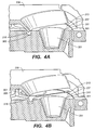
- FIG. 4 Greater detail near the heated pocket of one embodiment is shown in Figure 4.
- the pocket edge 311 shown in Figure 4 contains the heating position 207, and thus the pocket 201 shown in Figure 4 is the heated pocket.
- Figure 4a shows the source configured for coating, with the cover 209 in the "down" position. In the down position, the lip 215 extends into the groove 305 without making contact. The baffle thus formed extends around the pocket 201 far enough to provide a baffle between the heated and unheated pockets.
- Figure 4b shows the cover "up" position, in which the lip 215 is retracted from the groove 305, permitting rotation of the turreted crucible 301.
- a vertical clearance between lip 215 and the adjacent groove 305 should exceed approximately 0.005 inches for line-of-sight blocking, and may have a horizontal clearance between the lip edge closest to the heated pocket of as large as 0.050 inches to accommodate deposits.
- the cover and crucible baffle arrangement blocks contaminants from propagating from heated to unheated pockets by eliminating the line-of-sight movement of coating vapours. Due to the low pressure, vapours travel nearly unimpeded until they strike one of the surfaces within the system 101. Upon impact, a substantial amount of incident vapour molecules will stick to the surface, resulting in an accumulating deposit. By allowing sufficient clearance between baffle surfaces, deposits can accumulate over some period of time without presenting a source for cross-contamination. Thus the clearance between cover and crucible allows for deposits to accumulate on those surfaces without decreasing the ability of the baffle to block contaminants, since deposits further limit the line-of-sight, or to allow deposits to easily flake or rub off and contaminate other pockets.
- the arrangement of the cover in this invention stands in contrast to prior art covers that relied on small clearances to reduce contamination, either by limiting (but not eliminating) line-of-sight contamination or by sealing the cover and crucible. It is important that the cover and crucible meet without contact, yet cooperate to form a baffle between heated and unheated pockets, and be movable between multiple pockets. It is also desirable to allow space for deposits in such a way the deposits will not interfere with the noncontact line-of-sight baffle.
- cover and crucible will form the type of baffle to which this invention is directed, including, but not limited to, other cover lip and crucible groove shapes, a flat cover and a crucible with an edge that extends above the crucible, a cover with a groove and a crucible with a ridge, and combinations that result in more complex sinuous baffles. Additional contours or flat surfaces may also be included to separate deposits from crucible pockets.
- cross-contamination prevention configurations within the scope of the invention include pockets having non-circular openings, such as regular or irregularly shaped two-dimensional shapes, multiple pockets of varying sizes, including shapes and/or volumes, pockets arranged linearly or in multiple rows on the crucible surface, or arranged in a close packed configuration to increase the amount of usable crucible space on the crucible surface, or in multiple circular patterns.
- the relative motion between turret and cover should proceed in a manner that does not allow for the crucible and cover to contact.
- crucible selection motion and cover motion must be controlled to provided the stated advantages.
- contact between the baffle component, or between and any parts which have accumulated deposits should be minimized during pocket selection.
- Many different mechanisms and control systems could be configured to achieve those advantages.
- the cover and crucible form two halves of a baffle that would impede rotation of the turret 301.
- the first embodiment thus includes a rotation mechanism (not shown) for rotating the turret 301 to select from among the multiple pockets 201, and a lifting mechanism 300 to allow rotation without contact of the cover 209 and the turret 301.
- the rotation mechanisms couples the turret 301 to the source housing 217, and can be controlled by external devices not shown to rotate the turret 301 about an axis of rotation 303. By controlling the rotational position of the turret 301, any of the pockets 201 can be brought into the heating location 207.
- the rotation mechanism can consist of AC or DC motors or rotary or linear pneumatic actuators, and may also include sensors mounted on turret and housing to detect rotational position.
- Figure 5 shows a bottom perspective view shows the lifting mechanism 300, including an actuator 307 and rods 309 that provide lifting motion to the cover 209 (not shown). Also shown is the turreted crucible 301 and the electron beam source exit 203.
- the actuator 307 is a single action pneumatic actuator with a spring return enclosed in a bellows, with the spring forcing the cover into a normally up position.
- the actuator 307 is double acting, providing both raising and lower operations.
- Other lifting mechanism that could be used with this invention include, but are not limited to, lead screws, piezo-electric actuators, bimetallic elements, magnetic solenoid, and linear motors.
- the motion involved in lifting the cover is shown more clearly in the side view of Figure 6.
- the solid and dashed cover lifting components (actuator 307, rods 309 and cover 209) shows the extreme points of motion.
- the cover is connected at its corners through the rods 309 to the actuator 307.
- the lip 215 clears the obstructing crucible, and in the forced down, solid position, the cover 209 is fully engaged.
- the combination of a rotational and lifting mechanism is generally useful for rotational turrets as illustrated in the first embodiment, providing a way of covering and uncovering multiple pockets without allowing contact of surfaces which may have deposits, especially near pockets which may become contaminated.
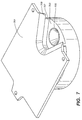
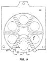
- Figures. 5 and 7 to 10 Details of a second embodiment of the invention is shown in Figures. 5 and 7 to 10, of which Figure 5 shows a bottom view of the cover lifting mechanism, Figure 7 is a perspective view, Figure 8 is an exploded perspective view, Figure 9 is a top view, and cross-sectional views of the cover are shown in an up configuration ( Figure 10a) and down configuration ( Figure 10b).
- a crucible cover 701 with a lip 709 is positioned over turreted crucible 703 which includes multiple pockets 705 and is rotatably mounted in a housing using techniques well known to those in the art for mounting and controlling crucible rotation, as discussed in the first embodiment.
- the cover 701 is liftably mounted to the housing, using the mechanism 300 as shown in Figure 5.
- the crucible 703 has a plurality of pockets 705, each of which has a barrier 707 extending away from crucible 703.
- the lip 709 is adapted to have approximately the same contour as the barrier 707, as is best seen in Figure 9.
- the cover 701 is aligned with the crucible 703 as shown in Figures 7 or 9, one of the pockets 705 is uncovered, with the lip 709 near the barrier 707 closest to the uncovered pocket.
- the edge of the uncovered pocket corresponds to the heating location 207, and thus the uncovered pocket is the heated pocket.
- the cover 701 Extending away from the cover 701 towards the crucible 703 are protrusions 801 that fit into the space between the barriers 707.
- the cover 701 has an external lifting and rotation mechanism (not shown) that moves the cover 701 away from the crucible 703, can rotate any of the pockets 705 within the lip 709 such that protrusions 801 fit within the barriers 707, and then lowers the cover onto the crucible, coming close to but not touching the ends of the barriers.
- the cover protrusions 801 By lowering the cover protrusions 801 below the tops of the barrier 707, the line-of-sight between the uncovered and all of the covered pockets is blocked.
- FIGs 10a and b are sectional views of Figure 9 taken through a heated pocket 1001 and an unheated pocket 1003.
- the cover 701 includes a protrusion 801 that forms a ledge 1005 near the lip 709.
- a ray 1007 is illustrative of a glancing trajectory of vapours that might leave the heated pocket 1001 and deposit on the cover 701.
- the cover 701 is situated below the ray 1007, thus reducing line-of-sight contamination of the cover. Contaminates migrating over the barrier 707 from the heated pocket 1001 towards the unheated pocket 1003 will accumulated on the cover 701 at the ledge 1005. This will restrict the flow of coating vapours towards unheated pockets and reduce cross-contamination.
- Figure 10b shows the cover 701 of the second embodiment in an "up" position, allowing for rotation of the turret 711 without contact between the barrier 707 and the cover 701.
- Line-of-sight blocking with the second embodiment is controlled independently of the shape of crucible contours, since blocking is not due to mutually mated surfaces as with the first embodiment.
- the degree of blocking can be varied by changing the protrusion 801 size and shape as well as the closest approach of the cover 701 with the crucible 703.
- preferred dimensions include barriers 707 that extends from approximately 0.1 inch to approximately 1 inch above the crucible 703 towards the cover 701, protrusions 801 that extend at least approximately 0.02 inch down from the lip 709 to form the ledge 1005, and a vertical clearance between the barrier 707 and the lip 709 of approximately 0.005 inch.
- an additional embodiments of the invention would have a fixed cover and a movable crucible, while other embodiments would be to have a cover that is hinged so that only part of the cover need be raised for turret motion, or the barrier may be designed such that a specific motion in a plane parallel to the crucible surface maneuvers the pockets into a selected position without a lifting motion.
Landscapes
- Chemical & Material Sciences (AREA)
- Organic Chemistry (AREA)
- Engineering & Computer Science (AREA)
- Materials Engineering (AREA)
- Mechanical Engineering (AREA)
- Metallurgy (AREA)
- Chemical Kinetics & Catalysis (AREA)
- Health & Medical Sciences (AREA)
- Toxicology (AREA)
- Physical Vapour Deposition (AREA)
- Crystals, And After-Treatments Of Crystals (AREA)
- Vaporization, Distillation, Condensation, Sublimation, And Cold Traps (AREA)
- Muffle Furnaces And Rotary Kilns (AREA)
Abstract
Description
Claims (11)
- A crucible cover for a multiple pocket vapour source, the vapour produced by an electron beam that can be directed to uncovered crucible pockets, comprising:a) a crucible having a crucible surface, the surface having a plurality of pockets for holding coating materials to be evaporative heated; andb) a crucible cover with a covering surface facing the crucible, where the pockets are covered or uncovered, and where there is at least one uncovered pocket and at least one covered pocket, such that the crucible surface and cover surface have cooperating surface features forming a line-of-sight blocking baffle the between the uncovered pockets and the covered pockets, whereby line-of-sight material contamination from heated vapours is reduced and that deposition on the cover and crucible does not result in cross-contamination between pockets.
- A cover according to Claim 1 in which the clearance between the crucible surface and cover surface adjacent to a heated pocket is greater than about 0.005 inch.
- A cover according to Claim 1 or Claim 2 in which at least a portion of the cover can move relative to the crucible, such that the cover can be moved between a down position for pocket covering and an up position to facilitate crucible rotation without interference between the cover and crucible.
- A cover according to any preceding claim in which the cooperating surface features are comprised of at least one recess on the crucible surface and a matching protrusion on the covering surface.
- A cover according to any preceding claim in which the cooperating surface feature nearest the covered pocket is comprised of a groove on the crucible surface and a matching protrusion on the covering surface, and where the cover surface protrusion is within line-of-sight of the heated pocket.
- A cover according to any preceding claim in which the cooperating surface features comprise a crucible barrier extending from the perimeter of the crucible pockets towards the covering surface and a matching protrusion on the covering surface towards said crucible pocket and adjacent to said crucible barrier.
- A covered, multiple pocket vapour source assembly, the vapour produced by an electron beam that can be directed to uncovered crucible pockets, comprising:a) a housing;b) a turreted crucible rotatably mounted within the housing, the crucible having a surface;c) a plurality of pockets in the crucible, the pockets adapted for containing coating materials, and the turreted crucible rotatable to bring any of the material pockets into a position to receive energy from the electron beam;d) a cover with a covering surface facing the crucible surface, the cover mounted to the housing, and the cover extending over all pockets not receiving energy; ande) matching pairs of cooperating surface features on the cover surface and crucible surface, such that the cooperating surface features form a line-of-sight blocking baffle the between the uncovered pockets and the covered pockets.
- An assembly according to Claim 7 in which the cooperating surface features includes a protrusion on the cover surface towards the crucible surface.
- An assembly according to Claim 7 or Claim 8 in which the clearance between the cooperating surface features adjacent to a heated pocket is greater than about 0.005 inch.
- An assembly according to any one of Claims 7 to 9 in which at least a portion of the cover is liftably connected to the housing, such that the cover can be moved between a down position for pocket covering and an up position to facilitate crucible rotation without interference between the cover and crucible.
- An assembly according to Claim 10 in which the cover is liftably connected to the housing with a pneumatic actuator.
Priority Applications (1)
| Application Number | Priority Date | Filing Date | Title |
|---|---|---|---|
| EP08153868A EP1967607A1 (en) | 2000-06-01 | 2001-05-31 | Electron beam evaporation source |
Applications Claiming Priority (2)
| Application Number | Priority Date | Filing Date | Title |
|---|---|---|---|
| US584940 | 2000-06-01 | ||
| US09/584,940 US6342103B1 (en) | 2000-06-01 | 2000-06-01 | Multiple pocket electron beam source |
Related Child Applications (1)
| Application Number | Title | Priority Date | Filing Date |
|---|---|---|---|
| EP08153868A Division EP1967607A1 (en) | 2000-06-01 | 2001-05-31 | Electron beam evaporation source |
Publications (3)
| Publication Number | Publication Date |
|---|---|
| EP1160351A2 true EP1160351A2 (en) | 2001-12-05 |
| EP1160351A3 EP1160351A3 (en) | 2004-01-28 |
| EP1160351B1 EP1160351B1 (en) | 2008-09-24 |
Family
ID=24339380
Family Applications (2)
| Application Number | Title | Priority Date | Filing Date |
|---|---|---|---|
| EP08153868A Withdrawn EP1967607A1 (en) | 2000-06-01 | 2001-05-31 | Electron beam evaporation source |
| EP01304805A Expired - Lifetime EP1160351B1 (en) | 2000-06-01 | 2001-05-31 | Covered, multiple pocket evaporation source assembly |
Family Applications Before (1)
| Application Number | Title | Priority Date | Filing Date |
|---|---|---|---|
| EP08153868A Withdrawn EP1967607A1 (en) | 2000-06-01 | 2001-05-31 | Electron beam evaporation source |
Country Status (6)
| Country | Link |
|---|---|
| US (2) | US6342103B1 (en) |
| EP (2) | EP1967607A1 (en) |
| JP (1) | JP4845286B2 (en) |
| AT (1) | ATE409245T1 (en) |
| DE (1) | DE60135890D1 (en) |
| DK (1) | DK1160351T3 (en) |
Cited By (10)
| Publication number | Priority date | Publication date | Assignee | Title |
|---|---|---|---|---|
| WO2004087986A1 (en) * | 2003-04-03 | 2004-10-14 | Microemissive Displays Limited | Method and apparatus for depositing material on a substrate |
| EP2365513A1 (en) * | 2010-03-09 | 2011-09-14 | ESSILOR INTERNATIONAL (Compagnie Générale d'Optique) | Protective envelope for an ion beam gun, vacuum deposition device using evaporation and including such a protective envelope and material deposition process |
| CN102337502A (en) * | 2010-07-19 | 2012-02-01 | 鸿富锦精密工业(深圳)有限公司 | Film material processing device and vapor deposition equipment with same |
| CN105018884A (en) * | 2015-07-30 | 2015-11-04 | 苏州方昇光电装备技术有限公司 | Small vacuum evaporation instrument |
| CN108704687A (en) * | 2018-05-03 | 2018-10-26 | 宁波大学 | A kind of circular glass fibrous filter membrane ranked and stacked pile formula fire ware |
| USD909439S1 (en) * | 2018-11-30 | 2021-02-02 | Ferrotec (Usa) Corporation | Two-piece crucible cover |
| EP3840012A1 (en) * | 2019-12-20 | 2021-06-23 | Essilor International | Optimized crucible assembly and method for physical vapor deposition |
| CN113564536A (en) * | 2021-06-11 | 2021-10-29 | 北京航空航天大学 | A device for realizing automatic evaporation of ceramic targets to prepare double-layer ceramic layers |
| EP3887562A4 (en) * | 2018-11-30 | 2022-08-24 | Ferrotec (USA) Corporation | CRUCIBLE LID FOR COATING WITH AN ELECTRON BEAM SOURCE |
| CN119980154A (en) * | 2025-04-11 | 2025-05-13 | 成都晨发泰达航空科技股份有限公司 | A heating device for preparing thermal barrier coating by electron beam physical vapor deposition (EB-PVD) |
Families Citing this family (33)
| Publication number | Priority date | Publication date | Assignee | Title |
|---|---|---|---|---|
| US6342103B1 (en) | 2000-06-01 | 2002-01-29 | The Boc Group, Inc. | Multiple pocket electron beam source |
| US6641674B2 (en) * | 2000-11-10 | 2003-11-04 | Helix Technology Inc. | Movable evaporation device |
| TWI275319B (en) * | 2002-02-05 | 2007-03-01 | Semiconductor Energy Lab | Manufacturing method and method of operating a manufacturing apparatus |
| TWI286044B (en) * | 2002-02-22 | 2007-08-21 | Semiconductor Energy Lab | Light-emitting device and method of manufacturing the same, and method of operating manufacturing apparatus |
| KR100671673B1 (en) * | 2005-03-09 | 2007-01-19 | 삼성에스디아이 주식회사 | Multiple vacuum deposition apparatus and control method |
| WO2007012342A1 (en) * | 2005-07-27 | 2007-02-01 | Applied Materials Gmbh & Co. Kg | Device for clamping and positioning an evaporator boat |
| CN100516284C (en) * | 2006-01-21 | 2009-07-22 | 鸿富锦精密工业(深圳)有限公司 | Equipment of coating by vaporization |
| KR20080007820A (en) * | 2006-07-18 | 2008-01-23 | 세메스 주식회사 | Rotary deposition source for thin film deposition and thin film deposition apparatus using the same |
| EP2113584A1 (en) | 2008-04-28 | 2009-11-04 | LightLab Sweden AB | Evaporation system |
| US8557045B2 (en) * | 2008-08-26 | 2013-10-15 | Colorado State University Research Foundation | Apparatus and method for fabricating photovoltaic modules using heated pocket deposition in a vacuum |
| US8480805B2 (en) * | 2010-04-16 | 2013-07-09 | Colorado State University Research Foundation | System and method for sealing a vapor deposition source |
| TW201202454A (en) * | 2010-07-07 | 2012-01-16 | Hon Hai Prec Ind Co Ltd | Processing apparatus for smoothing film material and evaporation deposition device with same |
| TW201204845A (en) * | 2010-07-16 | 2012-02-01 | Hon Hai Prec Ind Co Ltd | Processing apparatus for smoothing film material and evaporation deposition device with same |
| KR101671489B1 (en) * | 2010-07-29 | 2016-11-02 | 삼성디스플레이 주식회사 | Evaporation source for organic material and vapor depositing apparatus including the same |
| CN101942641B (en) * | 2010-09-08 | 2012-06-13 | 四川虹视显示技术有限公司 | Evaporation source device of OLED (Organic Light Emitting Diode) evaporator |
| KR20120138305A (en) * | 2011-06-14 | 2012-12-26 | 삼성디스플레이 주식회사 | Organic thin film deposition system and method for depositing organic film |
| WO2013153604A1 (en) * | 2012-04-09 | 2013-10-17 | 株式会社シンクロン | Electron gun device |
| JPWO2013153604A1 (en) * | 2012-04-09 | 2015-12-17 | 株式会社シンクロン | Electron gun equipment |
| WO2014006706A1 (en) * | 2012-07-04 | 2014-01-09 | 中外炉工業株式会社 | Vapor deposition device |
| KR101438734B1 (en) * | 2013-11-08 | 2014-11-03 | 우경금속주식회사 | Rotary-type heat treatment furnace |
| CN104789930B (en) * | 2015-04-24 | 2016-05-11 | 京东方科技集团股份有限公司 | Evaporated device and adopt the method for operating of this evaporated device |
| TWI737718B (en) * | 2016-04-25 | 2021-09-01 | 美商創新先進材料股份有限公司 | Deposition systems including effusion sources, and related methods |
| CN107326329A (en) * | 2017-08-31 | 2017-11-07 | 京东方科技集团股份有限公司 | Evaporation source and evaporation coating device |
| CN107604315B (en) * | 2017-09-21 | 2023-10-27 | 京东方科技集团股份有限公司 | A sealed crucible and an evaporation method using the same |
| USD939461S1 (en) | 2018-11-30 | 2021-12-28 | Ferrotec (Usa) Corporation | Two-piece crucible cover for coating with an electron beam source |
| DE102019102587B4 (en) * | 2019-02-01 | 2023-02-23 | Semikron Elektronik Gmbh & Co. Kg | Rotatable evaporative material receiver and apparatus therewith for coating semiconductor or other surfaces |
| USD973734S1 (en) * | 2019-08-06 | 2022-12-27 | Nxl Technologies Inc. | Blind shear |
| CN114836720A (en) * | 2019-10-04 | 2022-08-02 | 株式会社爱发科 | Vapor deposition source for vacuum vapor deposition device |
| KR102214048B1 (en) * | 2020-12-04 | 2021-02-10 | (주)엠엑스앤 | Cooling sheet attachment apparatus to focusing ring for semiconductor manufacturing apparatus |
| WO2022221038A1 (en) * | 2021-04-15 | 2022-10-20 | Applied Materials, Inc. | Evaporation source cooling mechanism |
| CN116770234B (en) * | 2023-06-25 | 2023-12-15 | 苏州佑伦真空设备科技有限公司 | Crucible device for preventing material mixing |
| JP7421002B1 (en) * | 2023-07-07 | 2024-01-23 | 株式会社アルバック | Electron beam evaporation unit |
| CN118361951B (en) * | 2024-06-18 | 2024-08-30 | 陕西陕航环境试验有限公司 | Box-type high-temperature furnace |
Family Cites Families (16)
| Publication number | Priority date | Publication date | Assignee | Title |
|---|---|---|---|---|
| US2482329A (en) | 1946-05-27 | 1949-09-20 | Rca Corp | Apparatus for selective vapor coating |
| US2853402A (en) * | 1954-08-06 | 1958-09-23 | Jr Marsden S Blois | Magnetic element and method for producing the same |
| US4108107A (en) | 1976-04-01 | 1978-08-22 | Airco, Inc. | Rotatable substrate holder for use in vacuum |
| DE2917841A1 (en) * | 1979-05-03 | 1980-11-13 | Leybold Heraeus Gmbh & Co Kg | EVAPORATOR FOR VACUUM EVAPORATION SYSTEMS |
| DE3316554C1 (en) | 1983-05-06 | 1984-07-12 | Dr. Johannes Heidenhain Gmbh, 8225 Traunreut | Evaporator device with jet heating for vapor deposition of several materials |
| CH663037A5 (en) * | 1985-02-05 | 1987-11-13 | Balzers Hochvakuum | STEAM SOURCE FOR VACUUM COATING SYSTEMS. |
| US4866239A (en) * | 1988-05-31 | 1989-09-12 | The Boc Group, Inc. | Vapor source assembly with crucible |
| DE59002513D1 (en) | 1989-02-09 | 1993-10-07 | Balzers Hochvakuum | Crucible cover for coating systems with an electron beam source. |
| US4983806A (en) * | 1990-03-01 | 1991-01-08 | Harper James L | Method and device for cooling electron beam gun |
| JP2913745B2 (en) | 1990-04-10 | 1999-06-28 | 松下電器産業株式会社 | Vacuum deposition equipment |
| US5473627A (en) | 1992-11-05 | 1995-12-05 | Mdc Vacuum Products Corporation | UHV rotating fluid delivery system |
| US5338913A (en) | 1992-12-28 | 1994-08-16 | Tfi Telemark | Electron beam gun with liquid cooled rotatable crucible |
| US5792521A (en) | 1996-04-18 | 1998-08-11 | General Electric Company | Method for forming a multilayer thermal barrier coating |
| US6012413A (en) * | 1998-03-10 | 2000-01-11 | Mdc Vacuum Products Corp. | Electron beam source for use with varying sizes of crucibles |
| US6342103B1 (en) | 2000-06-01 | 2002-01-29 | The Boc Group, Inc. | Multiple pocket electron beam source |
| US20030019849A1 (en) | 2001-07-16 | 2003-01-30 | Cameron Daniel Barton | Electron beam gun with water cooled interlocking crucible cover |
-
2000
- 2000-06-01 US US09/584,940 patent/US6342103B1/en not_active Expired - Lifetime
-
2001
- 2001-05-31 AT AT01304805T patent/ATE409245T1/en active
- 2001-05-31 EP EP08153868A patent/EP1967607A1/en not_active Withdrawn
- 2001-05-31 DK DK01304805T patent/DK1160351T3/en active
- 2001-05-31 DE DE60135890T patent/DE60135890D1/en not_active Expired - Lifetime
- 2001-05-31 EP EP01304805A patent/EP1160351B1/en not_active Expired - Lifetime
- 2001-06-01 JP JP2001167138A patent/JP4845286B2/en not_active Expired - Lifetime
- 2001-10-24 US US09/999,199 patent/US6902625B2/en not_active Expired - Lifetime
Cited By (16)
| Publication number | Priority date | Publication date | Assignee | Title |
|---|---|---|---|---|
| WO2004087986A1 (en) * | 2003-04-03 | 2004-10-14 | Microemissive Displays Limited | Method and apparatus for depositing material on a substrate |
| EP2365513A1 (en) * | 2010-03-09 | 2011-09-14 | ESSILOR INTERNATIONAL (Compagnie Générale d'Optique) | Protective envelope for an ion beam gun, vacuum deposition device using evaporation and including such a protective envelope and material deposition process |
| FR2957455A1 (en) * | 2010-03-09 | 2011-09-16 | Essilor Int | PROTECTIVE ENVELOPE FOR CANON IONS, DEVICE FOR DEPOSITING VACUUM EVAPORATION MATERIALS COMPRISING SUCH A PROTECTIVE ENVELOPE AND METHOD FOR DEPOSITING MATERIALS |
| US9099278B2 (en) | 2010-03-09 | 2015-08-04 | Essilor International (Compagnie Generale D'optique) | Protective enclosure for an ion gun, device for depositing materials through vacuum evaporation comprising such a protective enclosure and method for depositing materials |
| CN102337502A (en) * | 2010-07-19 | 2012-02-01 | 鸿富锦精密工业(深圳)有限公司 | Film material processing device and vapor deposition equipment with same |
| CN105018884A (en) * | 2015-07-30 | 2015-11-04 | 苏州方昇光电装备技术有限公司 | Small vacuum evaporation instrument |
| CN105018884B (en) * | 2015-07-30 | 2018-04-10 | 苏州方昇光电装备技术有限公司 | Instrument is deposited in a kind of small size vacuum |
| CN108704687A (en) * | 2018-05-03 | 2018-10-26 | 宁波大学 | A kind of circular glass fibrous filter membrane ranked and stacked pile formula fire ware |
| USD909439S1 (en) * | 2018-11-30 | 2021-02-02 | Ferrotec (Usa) Corporation | Two-piece crucible cover |
| EP3887562A4 (en) * | 2018-11-30 | 2022-08-24 | Ferrotec (USA) Corporation | CRUCIBLE LID FOR COATING WITH AN ELECTRON BEAM SOURCE |
| US11807935B2 (en) | 2018-11-30 | 2023-11-07 | Ferrotec (Usa) Corporation | Crucible cover for coating with an electron beam source |
| US12258659B2 (en) | 2018-11-30 | 2025-03-25 | Ferrotec (Usa) Corporation | Crucible cover for coating with an electron beam source |
| EP3840012A1 (en) * | 2019-12-20 | 2021-06-23 | Essilor International | Optimized crucible assembly and method for physical vapor deposition |
| WO2021123293A1 (en) * | 2019-12-20 | 2021-06-24 | Essilor International | Optimized crucible assembly and method for physical vapor deposition |
| CN113564536A (en) * | 2021-06-11 | 2021-10-29 | 北京航空航天大学 | A device for realizing automatic evaporation of ceramic targets to prepare double-layer ceramic layers |
| CN119980154A (en) * | 2025-04-11 | 2025-05-13 | 成都晨发泰达航空科技股份有限公司 | A heating device for preparing thermal barrier coating by electron beam physical vapor deposition (EB-PVD) |
Also Published As
| Publication number | Publication date |
|---|---|
| DK1160351T3 (en) | 2009-01-19 |
| DE60135890D1 (en) | 2008-11-06 |
| US6342103B1 (en) | 2002-01-29 |
| EP1967607A1 (en) | 2008-09-10 |
| EP1160351B1 (en) | 2008-09-24 |
| US6902625B2 (en) | 2005-06-07 |
| ATE409245T1 (en) | 2008-10-15 |
| US20020040682A1 (en) | 2002-04-11 |
| EP1160351A3 (en) | 2004-01-28 |
| JP4845286B2 (en) | 2011-12-28 |
| JP2002038256A (en) | 2002-02-06 |
Similar Documents
| Publication | Publication Date | Title |
|---|---|---|
| EP1160351B1 (en) | Covered, multiple pocket evaporation source assembly | |
| US12258659B2 (en) | Crucible cover for coating with an electron beam source | |
| US8932995B2 (en) | Combinatorial process system | |
| WO1998008997A2 (en) | A cylindrical carriage sputtering system | |
| WO1998008997A9 (en) | A cylindrical carriage sputtering system | |
| KR102003199B1 (en) | Substrate Processing Apparatus | |
| KR20140057208A (en) | Combinatorial and full substrate sputter deposition tool and method | |
| US11043406B2 (en) | Two piece shutter disk assembly with self-centering feature |
Legal Events
| Date | Code | Title | Description |
|---|---|---|---|
| PUAI | Public reference made under article 153(3) epc to a published international application that has entered the european phase |
Free format text: ORIGINAL CODE: 0009012 |
|
| AK | Designated contracting states |
Kind code of ref document: A2 Designated state(s): AT BE CH CY DE DK ES FI FR GB GR IE IT LI LU MC NL PT SE TR |
|
| AX | Request for extension of the european patent |
Free format text: AL;LT;LV;MK;RO;SI |
|
| PUAL | Search report despatched |
Free format text: ORIGINAL CODE: 0009013 |
|
| RIC1 | Information provided on ipc code assigned before grant |
Ipc: 7C 23C 14/24 B Ipc: 7C 23C 14/30 A |
|
| AK | Designated contracting states |
Kind code of ref document: A3 Designated state(s): AT BE CH CY DE DK ES FI FR GB GR IE IT LI LU MC NL PT SE TR |
|
| AX | Request for extension of the european patent |
Extension state: AL LT LV MK RO SI |
|
| 17P | Request for examination filed |
Effective date: 20040721 |
|
| AKX | Designation fees paid |
Designated state(s): AT BE CH CY DE DK ES FI FR GB GR IE IT LI LU MC NL PT SE TR |
|
| 17Q | First examination report despatched |
Effective date: 20060720 |
|
| 17Q | First examination report despatched |
Effective date: 20060720 |
|
| RAP1 | Party data changed (applicant data changed or rights of an application transferred) |
Owner name: BOC EDWARDS, INC. |
|
| RAP1 | Party data changed (applicant data changed or rights of an application transferred) |
Owner name: EDWARDS VACUUM, INC. |
|
| GRAP | Despatch of communication of intention to grant a patent |
Free format text: ORIGINAL CODE: EPIDOSNIGR1 |
|
| RTI1 | Title (correction) |
Free format text: COVERED, MULTIPLE POCKET EVAPORATION SOURCE ASSEMBLY |
|
| GRAS | Grant fee paid |
Free format text: ORIGINAL CODE: EPIDOSNIGR3 |
|
| GRAA | (expected) grant |
Free format text: ORIGINAL CODE: 0009210 |
|
| AK | Designated contracting states |
Kind code of ref document: B1 Designated state(s): AT BE CH CY DE DK ES FI FR GB GR IE IT LI LU MC NL PT SE TR |
|
| REG | Reference to a national code |
Ref country code: GB Ref legal event code: FG4D |
|
| REG | Reference to a national code |
Ref country code: CH Ref legal event code: EP Ref country code: CH Ref legal event code: NV Representative=s name: RIEDERER HASLER & PARTNER PATENTANWAELTE AG |
|
| REG | Reference to a national code |
Ref country code: IE Ref legal event code: FG4D |
|
| REF | Corresponds to: |
Ref document number: 60135890 Country of ref document: DE Date of ref document: 20081106 Kind code of ref document: P |
|
| REG | Reference to a national code |
Ref country code: SE Ref legal event code: TRGR |
|
| REG | Reference to a national code |
Ref country code: DK Ref legal event code: T3 |
|
| PG25 | Lapsed in a contracting state [announced via postgrant information from national office to epo] |
Ref country code: FI Free format text: LAPSE BECAUSE OF FAILURE TO SUBMIT A TRANSLATION OF THE DESCRIPTION OR TO PAY THE FEE WITHIN THE PRESCRIBED TIME-LIMIT Effective date: 20080924 |
|
| PG25 | Lapsed in a contracting state [announced via postgrant information from national office to epo] |
Ref country code: ES Free format text: LAPSE BECAUSE OF FAILURE TO SUBMIT A TRANSLATION OF THE DESCRIPTION OR TO PAY THE FEE WITHIN THE PRESCRIBED TIME-LIMIT Effective date: 20090104 |
|
| PG25 | Lapsed in a contracting state [announced via postgrant information from national office to epo] |
Ref country code: PT Free format text: LAPSE BECAUSE OF FAILURE TO SUBMIT A TRANSLATION OF THE DESCRIPTION OR TO PAY THE FEE WITHIN THE PRESCRIBED TIME-LIMIT Effective date: 20090224 |
|
| PLBE | No opposition filed within time limit |
Free format text: ORIGINAL CODE: 0009261 |
|
| STAA | Information on the status of an ep patent application or granted ep patent |
Free format text: STATUS: NO OPPOSITION FILED WITHIN TIME LIMIT |
|
| 26N | No opposition filed |
Effective date: 20090625 |
|
| PG25 | Lapsed in a contracting state [announced via postgrant information from national office to epo] |
Ref country code: MC Free format text: LAPSE BECAUSE OF NON-PAYMENT OF DUE FEES Effective date: 20090531 |
|
| REG | Reference to a national code |
Ref country code: CH Ref legal event code: PUE Owner name: FERROTEC (USA) CORPORATION Free format text: EDWARDS VACUUM, INC.#301 BALLARDVALE STREET#WILMINGTON, MA 01844 (US) -TRANSFER TO- FERROTEC (USA) CORPORATION#33 CONSTITUTION DRIVE#BEDFORD, NH 03110 (US) |
|
| REG | Reference to a national code |
Ref country code: GB Ref legal event code: 732E Free format text: REGISTERED BETWEEN 20100722 AND 20100728 |
|
| PG25 | Lapsed in a contracting state [announced via postgrant information from national office to epo] |
Ref country code: GR Free format text: LAPSE BECAUSE OF FAILURE TO SUBMIT A TRANSLATION OF THE DESCRIPTION OR TO PAY THE FEE WITHIN THE PRESCRIBED TIME-LIMIT Effective date: 20081225 |
|
| REG | Reference to a national code |
Ref country code: FR Ref legal event code: CA Ref country code: FR Ref legal event code: TP |
|
| REG | Reference to a national code |
Ref country code: CH Ref legal event code: NV Representative=s name: RIEDERER HASLER & PARTNER PATENTANWAELTE AG |
|
| REG | Reference to a national code |
Ref country code: NL Ref legal event code: SD Effective date: 20101202 |
|
| BECA | Be: change of holder's address |
Owner name: FERROTEC USA CORP.33 CONSTITUTION DRIVE, BEDFORD, Effective date: 20101206 |
|
| PG25 | Lapsed in a contracting state [announced via postgrant information from national office to epo] |
Ref country code: TR Free format text: LAPSE BECAUSE OF FAILURE TO SUBMIT A TRANSLATION OF THE DESCRIPTION OR TO PAY THE FEE WITHIN THE PRESCRIBED TIME-LIMIT Effective date: 20080924 |
|
| PG25 | Lapsed in a contracting state [announced via postgrant information from national office to epo] |
Ref country code: CY Free format text: LAPSE BECAUSE OF FAILURE TO SUBMIT A TRANSLATION OF THE DESCRIPTION OR TO PAY THE FEE WITHIN THE PRESCRIBED TIME-LIMIT Effective date: 20080924 |
|
| REG | Reference to a national code |
Ref country code: FR Ref legal event code: PLFP Year of fee payment: 16 |
|
| REG | Reference to a national code |
Ref country code: FR Ref legal event code: PLFP Year of fee payment: 17 |
|
| REG | Reference to a national code |
Ref country code: FR Ref legal event code: PLFP Year of fee payment: 18 |
|
| PGFP | Annual fee paid to national office [announced via postgrant information from national office to epo] |
Ref country code: LU Payment date: 20190521 Year of fee payment: 19 Ref country code: NL Payment date: 20190521 Year of fee payment: 19 |
|
| PGFP | Annual fee paid to national office [announced via postgrant information from national office to epo] |
Ref country code: AT Payment date: 20190603 Year of fee payment: 14 |
|
| PGFP | Annual fee paid to national office [announced via postgrant information from national office to epo] |
Ref country code: SE Payment date: 20190520 Year of fee payment: 19 |
|
| PGFP | Annual fee paid to national office [announced via postgrant information from national office to epo] |
Ref country code: DE Payment date: 20200528 Year of fee payment: 20 Ref country code: IE Payment date: 20200527 Year of fee payment: 20 Ref country code: CH Payment date: 20200518 Year of fee payment: 20 Ref country code: FR Payment date: 20200527 Year of fee payment: 20 |
|
| PGFP | Annual fee paid to national office [announced via postgrant information from national office to epo] |
Ref country code: GB Payment date: 20200416 Year of fee payment: 20 Ref country code: IT Payment date: 20200528 Year of fee payment: 20 Ref country code: BE Payment date: 20200527 Year of fee payment: 20 |
|
| REG | Reference to a national code |
Ref country code: DK Ref legal event code: EBP Effective date: 20200531 |
|
| REG | Reference to a national code |
Ref country code: NL Ref legal event code: MM Effective date: 20200601 |
|
| REG | Reference to a national code |
Ref country code: AT Ref legal event code: MM01 Ref document number: 409245 Country of ref document: AT Kind code of ref document: T Effective date: 20200531 |
|
| PG25 | Lapsed in a contracting state [announced via postgrant information from national office to epo] |
Ref country code: AT Free format text: LAPSE BECAUSE OF NON-PAYMENT OF DUE FEES Effective date: 20200531 |
|
| PG25 | Lapsed in a contracting state [announced via postgrant information from national office to epo] |
Ref country code: NL Free format text: LAPSE BECAUSE OF NON-PAYMENT OF DUE FEES Effective date: 20200601 |
|
| PG25 | Lapsed in a contracting state [announced via postgrant information from national office to epo] |
Ref country code: LU Free format text: LAPSE BECAUSE OF NON-PAYMENT OF DUE FEES Effective date: 20200531 |
|
| PG25 | Lapsed in a contracting state [announced via postgrant information from national office to epo] |
Ref country code: DK Free format text: LAPSE BECAUSE OF NON-PAYMENT OF DUE FEES Effective date: 20200531 |
|
| PG25 | Lapsed in a contracting state [announced via postgrant information from national office to epo] |
Ref country code: SE Free format text: LAPSE BECAUSE OF NON-PAYMENT OF DUE FEES Effective date: 20200601 |
|
| REG | Reference to a national code |
Ref country code: DE Ref legal event code: R071 Ref document number: 60135890 Country of ref document: DE |
|
| REG | Reference to a national code |
Ref country code: CH Ref legal event code: PL |
|
| REG | Reference to a national code |
Ref country code: GB Ref legal event code: PE20 Expiry date: 20210530 Ref country code: IE Ref legal event code: MK9A |
|
| REG | Reference to a national code |
Ref country code: BE Ref legal event code: MK Effective date: 20210531 |
|
| PG25 | Lapsed in a contracting state [announced via postgrant information from national office to epo] |
Ref country code: GB Free format text: LAPSE BECAUSE OF EXPIRATION OF PROTECTION Effective date: 20210530 Ref country code: IE Free format text: LAPSE BECAUSE OF EXPIRATION OF PROTECTION Effective date: 20210531 |
|
| REG | Reference to a national code |
Ref country code: SE Ref legal event code: EUG |