EP1160078A1 - Laminated material and method of bending laminated material - Google Patents
Laminated material and method of bending laminated material Download PDFInfo
- Publication number
- EP1160078A1 EP1160078A1 EP00902117A EP00902117A EP1160078A1 EP 1160078 A1 EP1160078 A1 EP 1160078A1 EP 00902117 A EP00902117 A EP 00902117A EP 00902117 A EP00902117 A EP 00902117A EP 1160078 A1 EP1160078 A1 EP 1160078A1
- Authority
- EP
- European Patent Office
- Prior art keywords
- surface plate
- bending
- base
- core material
- laminated material
- Prior art date
- Legal status (The legal status is an assumption and is not a legal conclusion. Google has not performed a legal analysis and makes no representation as to the accuracy of the status listed.)
- Granted
Links
Images







Classifications
-
- B—PERFORMING OPERATIONS; TRANSPORTING
- B21—MECHANICAL METAL-WORKING WITHOUT ESSENTIALLY REMOVING MATERIAL; PUNCHING METAL
- B21D—WORKING OR PROCESSING OF SHEET METAL OR METAL TUBES, RODS OR PROFILES WITHOUT ESSENTIALLY REMOVING MATERIAL; PUNCHING METAL
- B21D5/00—Bending sheet metal along straight lines, e.g. to form simple curves
-
- B—PERFORMING OPERATIONS; TRANSPORTING
- B21—MECHANICAL METAL-WORKING WITHOUT ESSENTIALLY REMOVING MATERIAL; PUNCHING METAL
- B21D—WORKING OR PROCESSING OF SHEET METAL OR METAL TUBES, RODS OR PROFILES WITHOUT ESSENTIALLY REMOVING MATERIAL; PUNCHING METAL
- B21D5/00—Bending sheet metal along straight lines, e.g. to form simple curves
- B21D5/04—Bending sheet metal along straight lines, e.g. to form simple curves on brakes making use of clamping means on one side of the work
-
- B—PERFORMING OPERATIONS; TRANSPORTING
- B21—MECHANICAL METAL-WORKING WITHOUT ESSENTIALLY REMOVING MATERIAL; PUNCHING METAL
- B21D—WORKING OR PROCESSING OF SHEET METAL OR METAL TUBES, RODS OR PROFILES WITHOUT ESSENTIALLY REMOVING MATERIAL; PUNCHING METAL
- B21D47/00—Making rigid structural elements or units, e.g. honeycomb structures
-
- B—PERFORMING OPERATIONS; TRANSPORTING
- B29—WORKING OF PLASTICS; WORKING OF SUBSTANCES IN A PLASTIC STATE IN GENERAL
- B29C—SHAPING OR JOINING OF PLASTICS; SHAPING OF MATERIAL IN A PLASTIC STATE, NOT OTHERWISE PROVIDED FOR; AFTER-TREATMENT OF THE SHAPED PRODUCTS, e.g. REPAIRING
- B29C53/00—Shaping by bending, folding, twisting, straightening or flattening; Apparatus therefor
- B29C53/02—Bending or folding
- B29C53/04—Bending or folding of plates or sheets
-
- B—PERFORMING OPERATIONS; TRANSPORTING
- B29—WORKING OF PLASTICS; WORKING OF SUBSTANCES IN A PLASTIC STATE IN GENERAL
- B29C—SHAPING OR JOINING OF PLASTICS; SHAPING OF MATERIAL IN A PLASTIC STATE, NOT OTHERWISE PROVIDED FOR; AFTER-TREATMENT OF THE SHAPED PRODUCTS, e.g. REPAIRING
- B29C53/00—Shaping by bending, folding, twisting, straightening or flattening; Apparatus therefor
- B29C53/02—Bending or folding
- B29C53/04—Bending or folding of plates or sheets
- B29C53/06—Forming folding lines by pressing or scoring
- B29C53/063—Forming folding lines by pressing or scoring combined with folding
- B29C53/066—Forming folding lines by pressing or scoring combined with folding and joining the sides of the folding line, e.g. "Abkantschweissen"
-
- B—PERFORMING OPERATIONS; TRANSPORTING
- B29—WORKING OF PLASTICS; WORKING OF SUBSTANCES IN A PLASTIC STATE IN GENERAL
- B29L—INDEXING SCHEME ASSOCIATED WITH SUBCLASS B29C, RELATING TO PARTICULAR ARTICLES
- B29L2007/00—Flat articles, e.g. films or sheets
- B29L2007/002—Panels; Plates; Sheets
-
- B—PERFORMING OPERATIONS; TRANSPORTING
- B29—WORKING OF PLASTICS; WORKING OF SUBSTANCES IN A PLASTIC STATE IN GENERAL
- B29L—INDEXING SCHEME ASSOCIATED WITH SUBCLASS B29C, RELATING TO PARTICULAR ARTICLES
- B29L2009/00—Layered products
-
- B—PERFORMING OPERATIONS; TRANSPORTING
- B29—WORKING OF PLASTICS; WORKING OF SUBSTANCES IN A PLASTIC STATE IN GENERAL
- B29L—INDEXING SCHEME ASSOCIATED WITH SUBCLASS B29C, RELATING TO PARTICULAR ARTICLES
- B29L2031/00—Other particular articles
- B29L2031/30—Vehicles, e.g. ships or aircraft, or body parts thereof
- B29L2031/3064—Trains
-
- Y—GENERAL TAGGING OF NEW TECHNOLOGICAL DEVELOPMENTS; GENERAL TAGGING OF CROSS-SECTIONAL TECHNOLOGIES SPANNING OVER SEVERAL SECTIONS OF THE IPC; TECHNICAL SUBJECTS COVERED BY FORMER USPC CROSS-REFERENCE ART COLLECTIONS [XRACs] AND DIGESTS
- Y10—TECHNICAL SUBJECTS COVERED BY FORMER USPC
- Y10T—TECHNICAL SUBJECTS COVERED BY FORMER US CLASSIFICATION
- Y10T156/00—Adhesive bonding and miscellaneous chemical manufacture
- Y10T156/10—Methods of surface bonding and/or assembly therefor
- Y10T156/1002—Methods of surface bonding and/or assembly therefor with permanent bending or reshaping or surface deformation of self sustaining lamina
-
- Y—GENERAL TAGGING OF NEW TECHNOLOGICAL DEVELOPMENTS; GENERAL TAGGING OF CROSS-SECTIONAL TECHNOLOGIES SPANNING OVER SEVERAL SECTIONS OF THE IPC; TECHNICAL SUBJECTS COVERED BY FORMER USPC CROSS-REFERENCE ART COLLECTIONS [XRACs] AND DIGESTS
- Y10—TECHNICAL SUBJECTS COVERED BY FORMER USPC
- Y10T—TECHNICAL SUBJECTS COVERED BY FORMER US CLASSIFICATION
- Y10T156/00—Adhesive bonding and miscellaneous chemical manufacture
- Y10T156/10—Methods of surface bonding and/or assembly therefor
- Y10T156/1002—Methods of surface bonding and/or assembly therefor with permanent bending or reshaping or surface deformation of self sustaining lamina
- Y10T156/1028—Methods of surface bonding and/or assembly therefor with permanent bending or reshaping or surface deformation of self sustaining lamina by bending, drawing or stretch forming sheet to assume shape of configured lamina while in contact therewith
-
- Y—GENERAL TAGGING OF NEW TECHNOLOGICAL DEVELOPMENTS; GENERAL TAGGING OF CROSS-SECTIONAL TECHNOLOGIES SPANNING OVER SEVERAL SECTIONS OF THE IPC; TECHNICAL SUBJECTS COVERED BY FORMER USPC CROSS-REFERENCE ART COLLECTIONS [XRACs] AND DIGESTS
- Y10—TECHNICAL SUBJECTS COVERED BY FORMER USPC
- Y10T—TECHNICAL SUBJECTS COVERED BY FORMER US CLASSIFICATION
- Y10T156/00—Adhesive bonding and miscellaneous chemical manufacture
- Y10T156/10—Methods of surface bonding and/or assembly therefor
- Y10T156/1002—Methods of surface bonding and/or assembly therefor with permanent bending or reshaping or surface deformation of self sustaining lamina
- Y10T156/1043—Subsequent to assembly
-
- Y—GENERAL TAGGING OF NEW TECHNOLOGICAL DEVELOPMENTS; GENERAL TAGGING OF CROSS-SECTIONAL TECHNOLOGIES SPANNING OVER SEVERAL SECTIONS OF THE IPC; TECHNICAL SUBJECTS COVERED BY FORMER USPC CROSS-REFERENCE ART COLLECTIONS [XRACs] AND DIGESTS
- Y10—TECHNICAL SUBJECTS COVERED BY FORMER USPC
- Y10T—TECHNICAL SUBJECTS COVERED BY FORMER US CLASSIFICATION
- Y10T428/00—Stock material or miscellaneous articles
- Y10T428/24—Structurally defined web or sheet [e.g., overall dimension, etc.]
- Y10T428/2419—Fold at edge
-
- Y—GENERAL TAGGING OF NEW TECHNOLOGICAL DEVELOPMENTS; GENERAL TAGGING OF CROSS-SECTIONAL TECHNOLOGIES SPANNING OVER SEVERAL SECTIONS OF THE IPC; TECHNICAL SUBJECTS COVERED BY FORMER USPC CROSS-REFERENCE ART COLLECTIONS [XRACs] AND DIGESTS
- Y10—TECHNICAL SUBJECTS COVERED BY FORMER USPC
- Y10T—TECHNICAL SUBJECTS COVERED BY FORMER US CLASSIFICATION
- Y10T428/00—Stock material or miscellaneous articles
- Y10T428/24—Structurally defined web or sheet [e.g., overall dimension, etc.]
- Y10T428/24628—Nonplanar uniform thickness material
Definitions
- the present invention relates to a method of bending a laminated material.
- a honeycomb panel having a core material using aramid as base material is mounted on a curve forming member, where it is bent and fixed, then the bent portion is heated, cooled and finished.
- Japanese Patent Laid-Open Publication No. 9-295050 discloses a method for bending a panel, wherein the panel is sandwiched between a jig having a curved surface and a wing, thereby bending the panel.
- Japanese Patent Laid-Open Publication No. 9-201624 discloses sandwiching with a fixed roll and a moving roll a panel having one end fixed, then moving the moving roll to bend the panel.
- Japanese Patent Laid-Open Publication No. 57-205661 discloses a method for bending a laminated board, including adhering a heat insulator to a metal plate, forming a V-shaped cut to the heat insulator adhered to the bending portion, adhering a heat insulator to a second metal plate, and bending said V-shaped portion.
- Japanese Utility Model Publication No. 2-8567 discloses providing a V-shaped cut to a sandwich panel from one side of the surface plate, and then bending the same. Lastly, an L-shaped bonding member is fixed to the surface plate having the V-shaped cut.
- the object of the present invention is to provide a laminated material relatively large in thickness and having a curved surface with small radius.
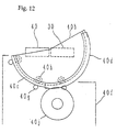
- FIGS. 1 through 16 A preferred embodiment of the present invention will now be explained with reference to FIGS. 1 through 16.
- the laminated material with a curved surface according to the present embodiment is used for example as the interior member of a railway car.
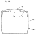
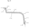
- FIGS. 13 through 16 show the example of a laminated material 170 with a curved surface formed according to the present embodiment constituting the interior portion of a railway car, mounted above a window 163 of a car body 160 to the ceiling 162.
- the laminated material 170 with a curved surface comprises, from the lower side thereof, a linear portion 171, a curved portion 172, a linear portion 173, and a linear portion 174.
- the material is bent approximately 90 degrees between the linear portion 173 and the linear portion 174.
- the upper and lower ends of the laminated material 170 are equipped with brackets 176, 177, which are fixed to the car body 160 with screw.
- the brackets 176, 176 are each fixed to the end portion of the laminated material 170 with a rivet and the like.
- Reference number 166 is the interior member on the ceiling.
- Plural number of laminated materials 170 are mounted along the longitudinal direction of the car body 160.
- a black sponge-like cushioning pad 168 is arranged at the joint between a laminated material 170 and another laminated material 170.
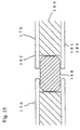
- the cushioning pad is arranged in the space defined by surface plates 181, 182 and core materials 183.
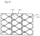
- the laminated material 170 comprises two surface plates 181 and 182, a core material 183 adhered to the two surface plates, a foam material 184 filled inside the cells of the core material 183, and an interior member 185 adhered to the surface plate 181 facing the interior of the car body (hereinafter called the inner-side surface plate).
- the core material 183 is made of paper, and is formed by laminating a ribbon bent in arc-like shapes from a single line. In FIG. 16, the areas shown by ⁇ are connected using adhesives. The areas shown by ⁇ are not adhered together. A foam material 184 is filled inside the cells.
- the direction of bend of the laminated material 170 as explained in the following is the left and right directions in FIG. 16.
- the interior member 185 is a face sheet made of vinyl chloride, and is adhered to the surface plate 181.
- the interior member 185 can be made using materials such as paper, cloth, or resin.
- the surface plates 181 and 182 are plates made of aluminum alloy and the like.
- the bracket 186 is mounted to the member after the bending process.
- a foaming resin material or an elastic foaming resin material and the like is injected to the cells of the core material 183, and it is formed therein.
- the core material 183 (in which the resin is foamed) is mounted via an adhesive on the surface plate 182, and then, the surface plate 181 having adhesive applied to one end thereof is superposed to the core material 183, thereby adhering the three members together.
- the adhesive is applied to the whole surface of the surface plate 182.
- the area to which the adhesive is applied on the surface plate 181 is limited to the range of the linear portions 73 and 74.
- the area of the surface plate 181 corresponding to the curved portion 172 and the linear portion 171 is not adhered to the core material 183.
- the interior member 185 is adhered to the surface plate 181.
- the size of the surface plates 181, 182 and the core material 183 is explained.
- the bend radius of the inner-side surface plate of the curved portion 172 is 150 mm
- the bend angle is approximately 80 degrees
- the thickness of the core material 183 is 39 mm.
- the size (width ⁇ length) of the core material 183 before the bending process is 1.2 m ⁇ 2.95 m
- the size (width ⁇ length) of the surface plate 182 before the bending process is 1.2 m ⁇ 3.0 m
- the size (width ⁇ length) of the surface plate 181 before the bending process is 1.15 m ⁇ 3.0 m.
- the widths mentioned above refer to the direction that the laminated material 170 is bent.
- the length of the surface plate 181 in the direction of bend is shorter than the length of the surface plate 182 or the core member 183.
- the surface plates 181 and 182 are made of aluminum alloy, and the thickness of the plates is 0.5 mm.
- the end of the surface plates 181 and 182 at the side of the linear portion 174 and the end surface of the core material 183 are substantially at the same position.
- the end of the surface plate 182 at the other end (at the side of the linear portion 171) and the end surface of the core material are substantially at the same position.
- the end of the surface plate 181 at this other end is receded from the end of the core material 183.
- said other end of the surface plate 181 reaches substantially the same position as the ends of the core member 183 and the surface plate 182.
- the position of the end of the surface plate 181 is set back from the end surface of the surface plate 182 considering the apparent length that the core material will shrink by the bending process.
- the length of the surface plate 181 is set accordingly.
- the width of the surface plates 181 and 182 are greater than the width of the core material 183.
- the core material 183 is positioned at the center of surface plates 181 and 182.
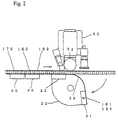
- the laminated material 170 is mounted on the bending device with the interior member 185 (as for the surface plate, the surface plate 181) facing downward.
- the laminated material 170 is placed on a base 21 of a bending jig 20, a fixing base 30, and a base 40 for flexion bending.
- the upper surfaces of each of the bases 21, 30 and 40 are positioned in a horizontally linear state.
- the base 21 supports the end portion (the mounting side of bracket 186) of the linear portion 171 of the laminated material 170.
- the bases 30 and 40 support the linear portions 173 and 174.
- Each base 21, 22, 30 and 40 has a vacuum suction pad placed on the surface to which the laminated material 170 contacts, and they are positioned with predetermined intervals along the width direction of the laminated material 170.
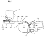
- a bending device 50 is lowered, then a bending roller 52 and a pressing roller 53 is lowered, pressing the material with such a force so as not to crush the core material 183.
- the lengths of the rollers 52 and 53 exceed the width of the surface plate 182.
- the suction pad of the base 21 sucks the interior member 185 downward.
- the bending jig 20 is rotated with the rotation center set to the center of the bend shape, winding the interior plate 185 (the surface plate 181) around the bending jig 20.
- the bending jig 20 is rotated until the base 22 of the jig 20 moves upward and contacts the interior plate 185. Thereby, the base 22 contacts the linear portion 173 of the laminated material 170.
- the base 22 is positioned on the same plane as the bases 30 and 40.
- the pressing roller 53 and the bending roller 52 contact the laminated material 170, preventing the core material 173 and the surface plate 181 from dropping to the right side.
- the bending jig 20 After fixing the interior plate 185 to the bending jig 20, the bending jig 20 is rotated so as to wind (bend) the interior plate 185 (including the surface plate 185) around the jig, so along with the rotation of the jig 20, the laminated material 170 is moved toward the direction of rotation (rightward in FIG. 2).
- the bases 30 and 40 should preferably be equipped with rollers to support the laminated material 170.
- the suction pad mounted to the base 22 sucks the interior plate 185 downward. Moreover, the suction pad mounted to bases 30 and 40 suck the interior plate 185 downward.
- the bases 30 and 40 are placed on the linear portions 173 and 174, respectively.
- the area between the bases 30 and 40 is the bend portion of the laminated material 170.
- the curved surface 23 of the bending jig 20 between the base 21 and base 22 to which the interior plate 185 contacts has the same radius as the radius of the curved surface portion 172 of the laminated material 170.
- the curved surface 23 is continuously formed along the width direction of the laminated material 170.
- an adhesive is applied to the surface of the plate 181 facing the core material 183 through a nozzle 61 of an application device. This is performed by directing a nozzle 161 toward the surface plate 181, and moving the same from one end of the laminated material 170 toward the other end thereof.
- the bending roller 52 and the pressing roller 53 are rotated so that the center of rotation is set to the rotation center of the bending jig 20.
- the amount of rotation of the rollers 52 and 53 are equal to the amount of rotation of the bending jig 20, or in other words, the angle of the curved portion 172.
- the core material 183 (the surface plate 182) is wound around the surface plate 181, and the core material 183 is adhered to the surface plate 181.
- the pressing roller 53 prevents the member (core material 183, surface plate 182) wound around the surface plate 181 by the bending roller 52 from separating from the plate 181 or the bending jig 20.
- a cylinder device 54 or a spring elastically supports the pressing roller 53. Therefore, even when rotated as shown in FIG. 4, the pressing roller 53 always contacts the surface plate 182. Further, the rotary axis of the bending roller 52 is positioned along the vertical line passing the rotary axis of the bending jig 20. The pressing roller 53 is placed leftward therefrom.
- a pressing pad 55 at the front end thereof is protruded so as to press the surface plate 182 (the core material 183) of the linear portion 171 against the bending jig 20.
- the laminated material 170 of the linear portion 171 is pressed against the base 21. The material is maintained at this state until the adhesive is completely cured.
- the bending roller 52, the pressing roller 53 and the pressing pad 55 is mounted to a single rotation device. The length of the pressing pad 55 exceeds the width of the laminated material 170.
- the pressing pad 55 is protruded by the cylinder device 56.
- the core material 183 together with the surface plate 182 is wound around the surface plate 181, so the core material 183 and the foam 184 inside the cells close to the surface plate 181 are compressed into the circumference direction, and collapsed or crushed. This absorbs the inner and outer circumferential differences created during the bending process.
- the core material 183 Since the core material 183 is not collapsed in the thickness direction, the strength of the material is not deteriorated. Furthermore, no gap or offset is generated between the surface plate 181 and the core material 183.
- the material of the surface plates 181 and 182 and the core material 183 are as mentioned, and when the cell size is 14 mm and the thickness of the core material 183 is 39 mm, the material can be bent to have an inner bend radius close to the thickness of the core material, without deteriorating the quality of the material, such as the buckling of the core material 183 or the breakage of the core material around the surface plate 182.
- This process enables to create a small radius bend. Therefore, the present embodiment enables to bend the laminated material 170 to have a relatively small bend radius.
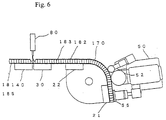
- a v-shaped cut is provided to the laminated material 170 using a circular saw 71 of a cutting device 70.
- the position to which the V-cut is provided is the flexion-bend position.
- the circular saw 71 cuts the surface plate 182 and the core material 183, leaving the surface plate 181.
- the circular saw 71 is tilted against the laminated material 170. After cutting one side of the V-shape, the circular saw 71 is rotated to cut the other side of the V.
- the cutting device moves along the line of bend.
- the cutting process can be performed after holding the laminated material 170 with the pressing pad 55.
- the portion cut off by the v-shape cut is removed manually from above. Or, the portion is sucked from above by a suction pad and removed therefrom. Or, the portion is pushed and removed from one end in the width direction of the laminated material 170 by a pusher.
- adhesive is applied through an application device 80 to the space formed by the V-cut.
- the application device 80 moves from one end in the width direction of the laminated material 170 to the other end, applying the adhesive.
- a bending base 40 rotates for a predetermined angle centering around the vertex of the V-cut portion, thereby bending the laminated material 170. This state is maintained until the adhesive cures completely.
- bent laminated material 170 is removed from the bending device.
- brackets 176 and 177 are mounted on the laminated material 170.
- the interior material 185 can be adhered to the laminated material after the bending process. If there is a need to fold the end of the surface plate 181 toward the core material 183, the end portion should be folded before the surface plate 181 is adhered to the core material 183.
- the non-bending areas of the two surface plates and the core material are adhered together before the bending process, but it can be adhered later.
- the adhesive can be applied after bending the inner surface plate, and then one end of the core material having the outer surface plate adhered thereto can be superposed to the inner surface plate, then the other end thereof can be bent.
- a crack can be formed to the bent portion when the base 40 performs the bending process. In such case, after bending the member, a bent plate is adhered to the surface plates 181 and 182.
- core material can be utilized as the core.
- FIG. 9 does not show the application device 60b.
- references 22a, 30a and 40a are suction pads.
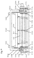
- An axis 20c is parallel to the axis 20b of the bending jig 20.
- the axis 20c is directly below the axis 20b.
- Axes 20b and 20c are connected at predetermined intervals along the axial direction by connecting members 20d.
- the connecting members 20d can rotate against the axes 20b and 20c.
- the axis 20b supports the bases 21 and 22 near the connecting members 20d.
- a bed 20x is placed under the axis 20c.
- the lower surface of the connecting members 20d are mounted on the bed 20 through seats 20y. Thereby, the bases 21 and 22 are prevented from being bent downward.
- the upper surfaces of the connecting members 20d are closer to the axis 20b than the base 21. Therefore, the surface of bases 21 and 22 are formed smoothly.
- a driving device 20e for rotating the axis 20b is mounted on the base 20f.
- the driving device 20e does not rotate the axis 20c.
- the driving device 20e comprises a motor.
- the bending roller 52, the pressing roller 53 and the pressing pad 55 of the bend device 50 are hung from a crossbeam 50b.
- the crossbeam 50b is hung from a crossbeam 50d via an elevating device 50c.
- the left and right ends of the beam 50d are supported by both ends of axis 20b through arms 50e, 50e.
- the left and right ends of the crossbeam 50b contact guide rails mounted to the inner sides of arms 50e, 50e. Thereby, even if the beams 50b and 50d rotate, the position of the bending roller 52 and the like is set to position at a predetermined distance from the axis 20b.
- the arm 50e is supported rotatably by the axis 20b.
- a driving device 50g for rotating the arm 50e is mounted to the base 20j on the other end of the axis 20b.
- the driving device 50g includes a motor.
- the output of the driving device 50g is transmitted through gears 50h, 50j, axis 20c, gears 50k and 50m to the right side arm 50e.
- the gears 50j and 50k are fixed to the axis 20c. Thereby, the axis 20c is rotated.
- the gear 50n mounted to the left side of the axis 20c rotates the gear 50p at the left end of the axis 20b. Thereby, the arm 50e on the left end is also rotated.
- the gear 50n is fixed to the axis 20c.
- Two legs on the left and right sides are positioned near the axis 20b of the left side of the arm 50e.
- the gear 50p is fixed to the leg next to it (hereinafter called the one leg).
- the gear 50p is rotatably supported by the axis 20b.
- the leg on the side of the driving device 20e (hereinafter called the other leg) is rotatably supported by the axis 20b.
- the right side arm 50e has two legs on the left and right sides near the axis 20b.
- the other leg on the arm 50e on the side of the gear 50h is rotatably supported by the axis 20b.
- the gear 50h is rotatably supported at the end portion of the axis 20b.
- the gear 50h is connected to the output shaft of the driving device 50g.
- the end of axis 20b is supported by the base 20j through gear 50h, the output shaft of the driving device 50g, and the body of the driving device 50g.
- the gear 50h is not fixed to said one leg.
- the leg on the side of the gear 50m (hereinafter called the leg on the other side) is fixed to the gear 50m.
- the gear 50m is rotatably supported by the axis 20b. Thereby, the rotation of the gear 50h rotates the arm 50e against the axis 20b via the gear 50j, 50k, and 50m.
- the left and right arms 50e, 50e rotate in synchronism. Further, when the driving device 50g stops the rotation, the arms 50e maintain their state.
- the bending roller 52 is divided into plural areas along the longitudinal direction of the crossbeam 50b. It is hung from the crossbeam 50b at the divided areas.
- the pressing roller 53 is divided into plural areas along the longitudinal direction of the crossbeam 50b. It is hung from the beam 50b at the divided areas via a cylinder device 54. The tip of the rod on the cylinder device 54 supports the axis of the roller 53.
- the pressing pad 55 is hung from the beam 50b through the cylinder device 56 at plural areas along the longitudinal direction of the beam 50b.
- the application device 60b is mounted on a rail 60d of the base 20x.
- the application device 60b moves from one end in the width direction of the bending jig 20 toward the other end thereof.
- the cutting device 70 and the application device 80 are mounted above a frame 70b.
- the frame 70b moves from one end of the bending jig 20 in the width direction toward the other end thereof along a rail 70x on a frame 40d.
- the rail 70x supports the frame 70b so that it will not fall down.
- the application device 60b and the frame 70b can be receded so as not to bump into the width-direction end of the laminated material 170.
- Semicircular flanges 40b are mounted to the left and right ends of the bending base 40. Each flange 40b is supported by the base 40f mounted to the base 20x.
- the base 40f is equipped with plural rollers 40g, 40h.
- the roller 40g supports the lower surface of the flange 40b.
- the roller 40h contacts the upper surface of a guide rail 40c of the flange 40b.
- the base 40 positioned between the left and right flanges 40b, 40b is equipped with flanges protruding downward in predetermined intervals. The lower surface of these flanges are supported by a roller mounted to the base 40f. This enables the flange 40b and the base 40 to rotate around a single rotary center without falling from the base 40f.
- a gear 40d is mounted to left and right flanges 40b.
- the gear 40d should be enough to cover the rotary angle of the base 40.
- a pinion gear 40j engaged to the gear 40d is equipped to the base 40f.
- the gear 40j is rotated by an axis 40k equipped to the base 40f.
- Reference 40m is a driving device that rotates the axis 40k.
- the base 30 is mounted to the frame 40d.
- the bases 20f, 20g, 20h and 20i of the bending jig 20 When the bases 20f, 20g, 20h and 20i of the bending jig 20 is relatively moved against the frame 40d so as to vary the distance between the bases and the frame, a laminated material having a varied distance between the arc-shaped curved portion and the flexion bend portion can be manufactured.
- the bases 20f, 20g, 20h and 20i can be moved along a rail.
- the radius of the bending jig 20 differs, the height of the bases 20f, 20g, 20h and 20i can be varied.
- the core material and the outer surface plate are bent after the inner surface plate is bent into an arc, so a laminated plate having a relatively small bend radius for its thickness is easily obtained.
Landscapes
- Engineering & Computer Science (AREA)
- Mechanical Engineering (AREA)
- Shaping Of Tube Ends By Bending Or Straightening (AREA)
- Laminated Bodies (AREA)
- Bending Of Plates, Rods, And Pipes (AREA)
Abstract
Description
Claims (26)
- A method of bending a laminated material comprising:while fixing one end of a laminated material having a first surface plate and a second surface plate respectively fixed to both sides of a core material on a base, moving and bending the other end of said first surface plate toward the direction separating from said core material;applying an adhesive to either one of the contact surfaces between said first surface plate and said core material at said other end; andmoving and bending said other end of said core material and said second surface plate along said first surface plate being bent, and adhering said core material to said second plate.
- A method of bending a laminated material according to claim 1, wherein the application of said adhesive is performed by spraying said adhesive toward the area between said first surface plate and said core material.
- A method of bending a laminated material according to claim 2, wherein the application of said adhesive is performed to said first surface plate.
- A method of bending a laminated material according to claim 2, wherein the means for spraying said adhesive performs said spraying while moving from one end of said first surface plate in the width direction toward the other end thereof.
- A method of bending a laminated material according to claim 1, wherein the bending of said first surface plate is performed by sucking said other end by a base positioned at said other end, and moving said base on said other end.
- A method of bending a laminated material according to claim 1 including:mounting said laminated material to a base or bases positioned along the horizontal direction; andthereafter, fixing said one end of said laminated material.
- A method of bending a laminated material according to claim 6, wherein the bending of said first surface plate is performed by sucking said other end downward by the base positioned at said other end; and
moving said base on said other end downward. - A method of bending a laminated material according to claim 1, wherein the bending of said first surface plate is performed by fixing said other end to an arc-shaped base; and
after fixing said one end to the base, rotating said base on said other end. - A method of bending a laminated material according to claim 1, wherein the bending of said core material and said second surface plate is performed by moving a roller from said one end thereof toward the other end, and at the same time, moving said roller toward said first surface plate.
- A method of bending a laminated material according to claim 9, wherein the fixing of said one end of said first surface plate to said base during the bending of said first surface plate is performed by pressing said laminated material onto said base by said roller.
- A method of bending a laminated material comprising:while fixing one end of a first surface plate, moving the other end of said first surface plate and bending it into an arc-shape;applying an adhesive to either one of the contact surfaces between said first surface plate and said core material at said other end; andwhile fixing the one end of the core material and a second surface plate adhered to said core material to the one end of said first surface plate, moving and bending the other end of said core material and said second surface plate along said first surface plate being bent, and adhering said core material to said second plate.
- A method of bending a laminated material comprising:while fixing one end of a first surface plate, moving the other end of said first surface plate and bending it into an arc-shape; andwhile fixing the one end of the core material and a second surface plate adhered to said core material to the one end of said first surface plate, moving and bending the other end of said core material and said second surface plate along said first surface plate being bent, and adhering said core material to said second plate.
- A method of bending a laminated material comprising:while fixing one end of a first surface plate, moving the other end of said first surface plate and bending it into an arc-shape; andwhile fixing the one end of the core material and a second surface plate adhered to said core material to the one end of said first surface plate, moving and bending the other end of said core material and said second surface plate along said first surface plate being bent, crushing the first-surface-plate side portion of said core material in the direction of the bend, and adhering said core material to said first surface plate.
- A method of bending a laminated material comprising:while fixing one end of a first surface plate, moving the other end of said first surface plate and bending it into an arc-shape; andwhile fixing the one end of the core material and a second surface plate adhered to said core material to the one end of said first surface plate, moving and bending the other end of said core material and said second surface plate along said first surface plate being bent, crushing the first-surface-plate side portion of said core material and a foam member filling the cell of said core material in the direction of the bend, and adhering said core material to said first surface plate.
- A laminated material comprising:a core material, and two surface plates bonded to both outside surfaces thereof; whereinsaid core material includes a plate positioned substantially orthogonal to said surface plates and bonding said two surface plates together;at least a portion of said laminated material has an arc-shaped curve with one surface positioned inward; andsaid core material at said arc-shaped area has the inward portion crushed in the direction of the arc.
- A laminated material according to claim 15, wherein:a foam material is filled to the plurality of cells of said core material; andthe foam material filled in the cells positioned in the first-surface-plate side of the arc-shaped area is crushed.
- A laminated material comprising:a core material, and two surface plates bonded to both outside surfaces thereof; whereinsubstantially the whole surface of one surface of said core material is adhered to one of said surface plates;one end of the other surface of said core material is adhered to one end of the other of said surface plate; andthe other end of said other surface of said core material is not adhered to the other end of said other surface plate.
- A laminated material according to claim 17, wherein the end portion of said other end of said other surface plate is positioned closer to said one end than the end portion of said other end of said core material.
- A laminated material according to claim 17, wherein said core material includes a plate positioned substantially orthogonal to said surface plates and bonding said two surface plates together, with cells positioned parallel to said plate; and
said cells are filled with foam material. - A laminated material according to claim 17, wherein a face material is adhered to the surface of one of said surface plates.
- A bending device of a laminated material comprising:a substantially horizontal first base for mounting a laminated material;a first suction pad mounted on the upper surface of said first base;a second base for mounting a laminated material together with said first base equipped with an arc-shaped portion, wherein the arc-shaped portion faces upward when said second base is rotated while said laminated material is mounted thereto;a second suction pad mounted on said second base to the position where said laminated material is to be mounted; anda roller capable of moving toward the second base and also capable of moving in the direction of rotation of said second base.
- A bending device of a laminated material according to claim 21, wherein said second base is equipped with a third suction pad for sucking the lower surface of a substantially horizontal laminated material when said second base is rotated.
- A bending device of a laminated material according to claim 21, wherein a third base is further equipped on the other side of said second base centering said first base;said third base is equipped with a suction pad positioned on the upper surface thereof;said third base is capable of rotating upward; anda cutting position is set between said third base and said second base, with a cutting device positioned above said cutting area.
- A bending device of a laminated material according to claim 22, wherein said second base is capable of moving relatively against said first base and said third base.
- A bending device of a laminated material according to claim 24, wherein said relative movement of said second base is in the horizontal direction.
- A bending device of a laminated material according to claim 24, wherein said relative movement of said second base is in the vertical direction.
Priority Applications (1)
| Application Number | Priority Date | Filing Date | Title |
|---|---|---|---|
| EP05021299A EP1695773A1 (en) | 1999-02-12 | 2000-02-07 | Laminated material and method of bending laminated material |
Applications Claiming Priority (3)
| Application Number | Priority Date | Filing Date | Title |
|---|---|---|---|
| JP03376899A JP3569150B2 (en) | 1999-02-12 | 1999-02-12 | Bending method of laminated material |
| JP3376899 | 1999-02-12 | ||
| PCT/JP2000/000649 WO2000047409A1 (en) | 1999-02-12 | 2000-02-07 | Laminated material and method of bending laminated material |
Related Child Applications (1)
| Application Number | Title | Priority Date | Filing Date |
|---|---|---|---|
| EP05021299A Division EP1695773A1 (en) | 1999-02-12 | 2000-02-07 | Laminated material and method of bending laminated material |
Publications (3)
| Publication Number | Publication Date |
|---|---|
| EP1160078A1 true EP1160078A1 (en) | 2001-12-05 |
| EP1160078A4 EP1160078A4 (en) | 2002-09-25 |
| EP1160078B1 EP1160078B1 (en) | 2006-08-02 |
Family
ID=12395638
Family Applications (2)
| Application Number | Title | Priority Date | Filing Date |
|---|---|---|---|
| EP05021299A Withdrawn EP1695773A1 (en) | 1999-02-12 | 2000-02-07 | Laminated material and method of bending laminated material |
| EP00902117A Expired - Lifetime EP1160078B1 (en) | 1999-02-12 | 2000-02-07 | Method and apparatus for bending laminated material |
Family Applications Before (1)
| Application Number | Title | Priority Date | Filing Date |
|---|---|---|---|
| EP05021299A Withdrawn EP1695773A1 (en) | 1999-02-12 | 2000-02-07 | Laminated material and method of bending laminated material |
Country Status (10)
| Country | Link |
|---|---|
| US (1) | US6899779B1 (en) |
| EP (2) | EP1695773A1 (en) |
| JP (1) | JP3569150B2 (en) |
| KR (1) | KR100505902B1 (en) |
| CN (1) | CN1163348C (en) |
| AU (1) | AU767113B2 (en) |
| DE (1) | DE60029760T2 (en) |
| ES (1) | ES2267495T3 (en) |
| TW (1) | TW592966B (en) |
| WO (1) | WO2000047409A1 (en) |
Cited By (4)
| Publication number | Priority date | Publication date | Assignee | Title |
|---|---|---|---|---|
| EP1136148A3 (en) * | 2000-03-16 | 2002-09-11 | Hitachi, Ltd. | Composite panel and method of bending the same |
| BE1016157A3 (en) * | 2004-08-12 | 2006-04-04 | Willem Jan Laane Trading Bv Me | Method for applying a fold belt in a plastic sheet. |
| CN1299891C (en) * | 2002-03-18 | 2007-02-14 | 桥本忠 | Plastic sheet with folding grid line and scoring tool used for the plastic sheet |
| EP3267083A1 (en) * | 2013-03-15 | 2018-01-10 | Fran Lanciaux | Method for producing clad duct, heat brake and clad duct |
Families Citing this family (14)
| Publication number | Priority date | Publication date | Assignee | Title |
|---|---|---|---|---|
| KR101140652B1 (en) * | 2009-07-16 | 2012-05-03 | 주식회사 국영지앤엠 | Space bar bending apparatus |
| JP5974324B2 (en) * | 2012-05-15 | 2016-08-23 | 株式会社ブリヂストン | Metal strip part forming apparatus and method |
| KR101462213B1 (en) * | 2013-03-11 | 2014-11-20 | (주)토탈테크 | Spiral Roll Bending Machine |
| CN103499009B (en) * | 2013-07-18 | 2016-08-10 | 浙江中隧桥波形钢腹板有限公司 | Small-radius bending member of thick steel plate and its extrusion forming equipment |
| CN105437524A (en) * | 2014-05-27 | 2016-03-30 | 致伸科技股份有限公司 | Electrode layer bending device of induction system |
| JP6069385B2 (en) * | 2015-02-27 | 2017-02-01 | アイダエンジニアリング株式会社 | Plate metal material bending apparatus and method |
| KR20180050108A (en) * | 2016-11-04 | 2018-05-14 | 주식회사 엘지화학 | Manufacturing system for laminated film and manufacturing method for laminated film |
| US10994876B2 (en) * | 2017-06-30 | 2021-05-04 | Divergent Technologies, Inc. | Automated wrapping of components in transport structures |
| IT201800007100A1 (en) * | 2018-07-11 | 2020-01-11 | Process for the manufacture of tubular products with complex curvature, such as ELM coils. | |
| KR102839083B1 (en) * | 2019-05-31 | 2025-07-28 | 엘지전자 주식회사 | Bending machine |
| CN113579013A (en) * | 2021-07-07 | 2021-11-02 | 安徽省伊锡尔重工科技有限公司 | Continuous bending machine for right-angle bending of metal plate |
| CN113751543A (en) * | 2021-08-13 | 2021-12-07 | 南京蓝昊智能科技有限公司 | Metal plate arc bending method |
| CN114210781B (en) * | 2021-11-29 | 2023-09-05 | 江苏盛翔电子科技有限公司 | Bending equipment for honeycomb panel core material production |
| CN116811208A (en) * | 2023-03-16 | 2023-09-29 | 景德镇昌河航空设备技术有限责任公司 | Bending device and method for interior trim plate material for aircraft cabin |
Family Cites Families (11)
| Publication number | Priority date | Publication date | Assignee | Title |
|---|---|---|---|---|
| US3890108A (en) * | 1973-02-09 | 1975-06-17 | Hughes Aircraft Co | Structural panel bent from laminated honeycomb |
| US4078959A (en) * | 1976-02-13 | 1978-03-14 | The Dow Chemical Company | Curved laminate panels |
| JPS62196132A (en) * | 1986-02-22 | 1987-08-29 | スズキ株式会社 | Method of molding honeycomb structure |
| JPH0622955B2 (en) * | 1986-03-21 | 1994-03-30 | マツダ株式会社 | Manufacturing method of honeycomb panel structure |
| US4853018A (en) * | 1987-11-23 | 1989-08-01 | Ford Motor Company | Method and apparatus for forming a glass sheet |
| US4917747A (en) * | 1989-02-24 | 1990-04-17 | The Boeing Company | Method of making crushed core molded panels |
| EP0424312A1 (en) * | 1989-10-13 | 1991-04-24 | Alusuisse-Lonza Services Ag | Flexible laminate |
| JPH03222715A (en) * | 1990-01-30 | 1991-10-01 | Showa Aircraft Ind Co Ltd | Molding method for honeycomb panel having curved surface |
| JPH07108634A (en) * | 1993-10-08 | 1995-04-25 | Sumitomo Light Metal Ind Ltd | Honeycomb panel manufacturing method |
| JPH09295050A (en) * | 1996-04-26 | 1997-11-18 | Sumitomo Bakelite Co Ltd | Method and device for bending of metal core dressing plate |
| US6036802A (en) * | 1996-09-13 | 2000-03-14 | The Boeing Company | Thermoplastic panel bending |
-
1999
- 1999-02-12 JP JP03376899A patent/JP3569150B2/en not_active Expired - Fee Related
-
2000
- 2000-01-27 TW TW089101419A patent/TW592966B/en not_active IP Right Cessation
- 2000-02-07 EP EP05021299A patent/EP1695773A1/en not_active Withdrawn
- 2000-02-07 CN CNB008026661A patent/CN1163348C/en not_active Expired - Fee Related
- 2000-02-07 ES ES00902117T patent/ES2267495T3/en not_active Expired - Lifetime
- 2000-02-07 US US09/890,580 patent/US6899779B1/en not_active Expired - Fee Related
- 2000-02-07 DE DE60029760T patent/DE60029760T2/en not_active Expired - Fee Related
- 2000-02-07 WO PCT/JP2000/000649 patent/WO2000047409A1/en not_active Ceased
- 2000-02-07 EP EP00902117A patent/EP1160078B1/en not_active Expired - Lifetime
- 2000-02-07 AU AU23269/00A patent/AU767113B2/en not_active Ceased
- 2000-02-07 KR KR10-2001-7010005A patent/KR100505902B1/en not_active Expired - Fee Related
Cited By (4)
| Publication number | Priority date | Publication date | Assignee | Title |
|---|---|---|---|---|
| EP1136148A3 (en) * | 2000-03-16 | 2002-09-11 | Hitachi, Ltd. | Composite panel and method of bending the same |
| CN1299891C (en) * | 2002-03-18 | 2007-02-14 | 桥本忠 | Plastic sheet with folding grid line and scoring tool used for the plastic sheet |
| BE1016157A3 (en) * | 2004-08-12 | 2006-04-04 | Willem Jan Laane Trading Bv Me | Method for applying a fold belt in a plastic sheet. |
| EP3267083A1 (en) * | 2013-03-15 | 2018-01-10 | Fran Lanciaux | Method for producing clad duct, heat brake and clad duct |
Also Published As
| Publication number | Publication date |
|---|---|
| DE60029760T2 (en) | 2007-08-02 |
| CN1336870A (en) | 2002-02-20 |
| DE60029760D1 (en) | 2006-09-14 |
| US6899779B1 (en) | 2005-05-31 |
| AU2326900A (en) | 2000-08-29 |
| JP2000229352A (en) | 2000-08-22 |
| TW592966B (en) | 2004-06-21 |
| ES2267495T3 (en) | 2007-03-16 |
| CN1163348C (en) | 2004-08-25 |
| JP3569150B2 (en) | 2004-09-22 |
| KR100505902B1 (en) | 2005-08-04 |
| WO2000047409A1 (en) | 2000-08-17 |
| EP1695773A1 (en) | 2006-08-30 |
| EP1160078A4 (en) | 2002-09-25 |
| KR20010101830A (en) | 2001-11-14 |
| AU767113B2 (en) | 2003-10-30 |
| EP1160078B1 (en) | 2006-08-02 |
Similar Documents
| Publication | Publication Date | Title |
|---|---|---|
| EP1160078B1 (en) | Method and apparatus for bending laminated material | |
| US6797364B2 (en) | Composite panel | |
| JP3836618B2 (en) | Laminate bending machine | |
| JP3828381B2 (en) | Laminate bending machine | |
| CN209834096U (en) | Be applied to automatic tectorial membrane mechanism of frame subsides dress before TV set | |
| JP2000229366A (en) | Laminated material | |
| CN222628777U (en) | Surrounding frame side edge sealing and stripping equipment | |
| EP0765220B1 (en) | Machine for making honeycomb material | |
| CN219770272U (en) | Automatic laminating equipment | |
| JP4006077B2 (en) | Inorganic fiber board skin applicator | |
| CN223833299U (en) | Buffering structure of numerical control bending machine | |
| CN223657250U (en) | Furniture board bordures bending device | |
| CN222309903U (en) | Film Laminating and Cutting Machine | |
| CN221316844U (en) | Automatic laminating equipment for laminating packaging plate | |
| JP2761819B2 (en) | Method and apparatus for attaching inorganic fiber board to outer skin | |
| CN222242346U (en) | Continuous stamping device for automobile damping plate | |
| CN116871892B (en) | A method for manufacturing aluminum material for solar photovoltaic support | |
| CN120941813A (en) | An automated processing device for packaging boxes | |
| CN220129635U (en) | Automatic forming machine for packing box | |
| CN217554357U (en) | Carton packing machine | |
| CN117948022A (en) | Insulating glass strip winding device and method | |
| CN113998317A (en) | Edge sealing steel belt sectioning and flattening device for steel belt box production | |
| CN119240102A (en) | Packaging bag corner wrapping device | |
| JPH09132164A (en) | Roof outer plate mounting structure of van type vehicle, method thereof, and roof outer plate bending device and fixing device | |
| WO2001012419A1 (en) | Method and device for manufacturing a window pane with resin frame |
Legal Events
| Date | Code | Title | Description |
|---|---|---|---|
| PUAI | Public reference made under article 153(3) epc to a published international application that has entered the european phase |
Free format text: ORIGINAL CODE: 0009012 |
|
| 17P | Request for examination filed |
Effective date: 20010808 |
|
| AK | Designated contracting states |
Kind code of ref document: A1 Designated state(s): AT BE CH CY DE DK ES FI FR GB GR IE IT LI LU MC NL PT SE Kind code of ref document: A1 Designated state(s): DE ES FR GB IT |
|
| A4 | Supplementary search report drawn up and despatched |
Effective date: 20020808 |
|
| AK | Designated contracting states |
Kind code of ref document: A4 Designated state(s): DE ES FR GB IT |
|
| RIC1 | Information provided on ipc code assigned before grant |
Free format text: 7B 32B 31/00 A, 7B 21D 47/00 B, 7B 29C 53/04 B, 7B 29C 53/06 B, 7B 21D 5/00 B, 7B 31D 3/00 B |
|
| RBV | Designated contracting states (corrected) |
Designated state(s): DE ES FR GB IT |
|
| 17Q | First examination report despatched |
Effective date: 20050308 |
|
| GRAP | Despatch of communication of intention to grant a patent |
Free format text: ORIGINAL CODE: EPIDOSNIGR1 |
|
| RTI1 | Title (correction) |
Free format text: METHOD AND APPARATUS FOR BENDING LAMINATED MATERIAL |
|
| RIC1 | Information provided on ipc code assigned before grant |
Ipc: B21D 5/00 20060101AFI20060309BHEP |
|
| GRAS | Grant fee paid |
Free format text: ORIGINAL CODE: EPIDOSNIGR3 |
|
| GRAA | (expected) grant |
Free format text: ORIGINAL CODE: 0009210 |
|
| AK | Designated contracting states |
Kind code of ref document: B1 Designated state(s): DE ES FR GB IT |
|
| PG25 | Lapsed in a contracting state [announced via postgrant information from national office to epo] |
Ref country code: IT Free format text: LAPSE BECAUSE OF FAILURE TO SUBMIT A TRANSLATION OF THE DESCRIPTION OR TO PAY THE FEE WITHIN THE PRESCRIBED TIME-LIMIT;WARNING: LAPSES OF ITALIAN PATENTS WITH EFFECTIVE DATE BEFORE 2007 MAY HAVE OCCURRED AT ANY TIME BEFORE 2007. THE CORRECT EFFECTIVE DATE MAY BE DIFFERENT FROM THE ONE RECORDED. Effective date: 20060802 |
|
| REG | Reference to a national code |
Ref country code: GB Ref legal event code: FG4D |
|
| REF | Corresponds to: |
Ref document number: 60029760 Country of ref document: DE Date of ref document: 20060914 Kind code of ref document: P |
|
| ET | Fr: translation filed | ||
| REG | Reference to a national code |
Ref country code: ES Ref legal event code: FG2A Ref document number: 2267495 Country of ref document: ES Kind code of ref document: T3 |
|
| PLBE | No opposition filed within time limit |
Free format text: ORIGINAL CODE: 0009261 |
|
| STAA | Information on the status of an ep patent application or granted ep patent |
Free format text: STATUS: NO OPPOSITION FILED WITHIN TIME LIMIT |
|
| 26N | No opposition filed |
Effective date: 20070503 |
|
| PGFP | Annual fee paid to national office [announced via postgrant information from national office to epo] |
Ref country code: ES Payment date: 20080204 Year of fee payment: 9 |
|
| PGFP | Annual fee paid to national office [announced via postgrant information from national office to epo] |
Ref country code: GB Payment date: 20080114 Year of fee payment: 9 Ref country code: IT Payment date: 20080129 Year of fee payment: 9 |
|
| PGFP | Annual fee paid to national office [announced via postgrant information from national office to epo] |
Ref country code: DE Payment date: 20080307 Year of fee payment: 9 Ref country code: FR Payment date: 20080111 Year of fee payment: 9 |
|
| GBPC | Gb: european patent ceased through non-payment of renewal fee |
Effective date: 20090207 |
|
| REG | Reference to a national code |
Ref country code: FR Ref legal event code: ST Effective date: 20091030 |
|
| PG25 | Lapsed in a contracting state [announced via postgrant information from national office to epo] |
Ref country code: DE Free format text: LAPSE BECAUSE OF NON-PAYMENT OF DUE FEES Effective date: 20090901 |
|
| REG | Reference to a national code |
Ref country code: ES Ref legal event code: FD2A Effective date: 20090209 |
|
| PG25 | Lapsed in a contracting state [announced via postgrant information from national office to epo] |
Ref country code: GB Free format text: LAPSE BECAUSE OF NON-PAYMENT OF DUE FEES Effective date: 20090207 Ref country code: FR Free format text: LAPSE BECAUSE OF NON-PAYMENT OF DUE FEES Effective date: 20090302 |
|
| PG25 | Lapsed in a contracting state [announced via postgrant information from national office to epo] |
Ref country code: ES Free format text: LAPSE BECAUSE OF NON-PAYMENT OF DUE FEES Effective date: 20090209 |
|
| PG25 | Lapsed in a contracting state [announced via postgrant information from national office to epo] |
Ref country code: IT Free format text: LAPSE BECAUSE OF NON-PAYMENT OF DUE FEES Effective date: 20090207 |