EP1160017A2 - Automated pitch button dispensing station and method - Google Patents

Automated pitch button dispensing station and method Download PDF

Info

Publication number
EP1160017A2
EP1160017A2 EP01108210A EP01108210A EP1160017A2 EP 1160017 A2 EP1160017 A2 EP 1160017A2 EP 01108210 A EP01108210 A EP 01108210A EP 01108210 A EP01108210 A EP 01108210A EP 1160017 A2 EP1160017 A2 EP 1160017A2
Authority
EP
European Patent Office
Prior art keywords
positioning
dispenser
stage
workpiece
pitch
Prior art date
Legal status (The legal status is an assumption and is not a legal conclusion. Google has not performed a legal analysis and makes no representation as to the accuracy of the status listed.)
Withdrawn
Application number
EP01108210A
Other languages
German (de)
French (fr)
Other versions
EP1160017A3 (en
Inventor
Richard Des Jardin
Current Assignee (The listed assignees may be inaccurate. Google has not performed a legal analysis and makes no representation or warranty as to the accuracy of the list.)
Agilent Technologies Inc
Original Assignee
Agilent Technologies Inc
Priority date (The priority date is an assumption and is not a legal conclusion. Google has not performed a legal analysis and makes no representation as to the accuracy of the date listed.)
Filing date
Publication date
Application filed by Agilent Technologies Inc filed Critical Agilent Technologies Inc
Publication of EP1160017A2 publication Critical patent/EP1160017A2/en
Publication of EP1160017A3 publication Critical patent/EP1160017A3/en
Withdrawn legal-status Critical Current

Links

Images

Classifications

    • B—PERFORMING OPERATIONS; TRANSPORTING
    • B05—SPRAYING OR ATOMISING IN GENERAL; APPLYING FLUENT MATERIALS TO SURFACES, IN GENERAL
    • B05C—APPARATUS FOR APPLYING FLUENT MATERIALS TO SURFACES, IN GENERAL
    • B05C13/00—Means for manipulating or holding work, e.g. for separate articles
    • B05C13/02—Means for manipulating or holding work, e.g. for separate articles for particular articles
    • B—PERFORMING OPERATIONS; TRANSPORTING
    • B05—SPRAYING OR ATOMISING IN GENERAL; APPLYING FLUENT MATERIALS TO SURFACES, IN GENERAL
    • B05C—APPARATUS FOR APPLYING FLUENT MATERIALS TO SURFACES, IN GENERAL
    • B05C5/00—Apparatus in which liquid or other fluent material is projected, poured or allowed to flow on to the surface of the work
    • B05C5/02—Apparatus in which liquid or other fluent material is projected, poured or allowed to flow on to the surface of the work the liquid or other fluent material being discharged through an outlet orifice by pressure, e.g. from an outlet device in contact or almost in contact, with the work
    • B05C5/0208—Apparatus in which liquid or other fluent material is projected, poured or allowed to flow on to the surface of the work the liquid or other fluent material being discharged through an outlet orifice by pressure, e.g. from an outlet device in contact or almost in contact, with the work for applying liquid or other fluent material to separate articles
    • B05C5/0212—Apparatus in which liquid or other fluent material is projected, poured or allowed to flow on to the surface of the work the liquid or other fluent material being discharged through an outlet orifice by pressure, e.g. from an outlet device in contact or almost in contact, with the work for applying liquid or other fluent material to separate articles only at particular parts of the articles

Definitions

  • the present invention relates to manufacturing equipment and methods, particularly equipment and procedures which may be involved in the making of optical items, such as polarizing beam splitter (“PBS”) prism assemblies, for use in, for example, interferometers and other optical products. More particularly, the present invention relates to blocking technology, i.e., holding or supporting technology, for holding prisms or other optical workpieces or items in a selected position for performing work on them efficiently, with precision, and without inducing strain that could deform them.
  • PBS polarizing beam splitter
  • Blocking or supporting optical elements is known in the manufacture and treatment of high precision optics and optical items such as prisms, mirrors, lenses, windows and the like.
  • One method of blocking may involve a blocking tool and the use of pitch "buttons.”
  • the buttons comprise deposits of blocking pitch, usually in the form of small discs, which are applied to a surface or surfaces of the optic being blocked or supported.
  • the pitch button size, form factor, location on the optic surface and adherent qualities are variables which may affect the blocking process.
  • pitch button blocking is done by hand, using trained experts who apply a selected number of buttons, of a selected size, to a selected location or locations on a workpiece.
  • the process is very time consuming and requires highly trained operators and experts, and thus is currently labor intensive. Even using trained technicians, it typically takes one to two days to "button" a set of prisms using the traditional, known methods.
  • buttons-to-button volume variation using traditional methods is typically greater than 60%.
  • the present invention provides an apparatus or system and method for dispensing or applying a selected amount of supporting or holding material to a selected location on a workpiece.
  • the present invention provides a work station and method for applying a blocking material, such as pitch or the like, to a selected location on a workpiece
  • the work station includes an automated blocking material dispenser, a positioning stage for positioning the workpiece and a microprocessor
  • the method includes the synchronized and complimentary operation of the positioning stage and the dispenser under control of the microprocessor to deposit a selected amount and shape of the blocking material in a selected location or locations on a workpiece or workpieces with a high degree of repeatability in a short cycle time.
  • the present invention provides a work station comprising an automated pitch dispenser for dispensing or applying one or more pitch buttons to a workpiece or workpieces, and a positioning stage for positioning the workpiece(s), wherein the dispenser and positioning stage are coordinately operated and controlled by a suitable computer or microprocessor and software.
  • the work station may include appropriate peripheral devices and apparatus such as a preheating oven, sensing or process monitoring devices, and workpiece carriers and/or tool holders.
  • the method of use or operation of the pitch button station of the present invention comprises the positioning stage, for example an X-Y stage, moving or positioning a workpiece or workpieces, such as pre-heated optics, relative to a pitch dispenser, and the dispenser depositing pitch buttons on the positioned workpiece(s).
  • the pitch dispenser and the X-Y stage are controlled by a computer and appropriate software or program(s)
  • the buttons are positioned at precise, selected positions, in a precise selected size, in a very short cycle time, and with a high degree of repeatability.
  • An advantage of the present invention is that it speeds the "buttoning" process from the typical one to two days to button a set of prisms using known methods to about an hour.
  • button volume variants are expected to decrease to less than 8%. This is advantageous because it creates greater process consistency, resulting in reduced polishing time and better flatness control of the optics.
  • the pitch button apparatus and method of the present invention will help reduce manufacturing costs and new product introduction costs by using a continuous process. It will further the goal of developing manufacturing processes which enable fast response to market needs. It will facilitate the development of high and consistent yields of optics, reduce process variability, and provide for the easier, more accurate monitoring and accumulation of cost and quality information and management.
  • Additional advantages of automating pitch button blocking in accordance with the present invention include shortening lead time, removing the need for as many experts in the buttoning process, allowing achievement of better flatness control, increasing yields through greater blocking process consistency and supporting production goals, particularly as regards certain optics, such as 1 inch, 2 inch x 1 inch, and 4 inch x 1 inch prisms, from a common blank and fabrication process.
  • the apparatus and method of the present invention saves money and provides for increased production levels.
  • the pitch button dispensing station of the present invention is a customized work station which automatically deposits pitch buttons on prisms.
  • the pitch button dispensing station system or assembly of the present invention may be incorporated conveniently into current manufacturing lines and/or facilities, and it may be adapted or configured to improve and/or conform to a particular material flow.
  • Figure I is a front elevational view of one embodiment of the pitch button dispensing station in accordance with the present invention.
  • Figure 2 is a top plan view of the embodiment depicted in Figure 1.
  • Figure 3 is a side elevational view, partially in cross-section, of the dispenser head of the embodiment depicted in Figure 1.
  • Figure 4 is a front elevational view, partially in cross-section, of the dispenser head.
  • Figure 5 is a front elevational view, partially in cross-section, of the embodiment depicted is Figure 1.
  • Figure 6 depicts the one operational effect or result of the pitch button station and method of the present invention.
  • Figure 7 is a front elevational of another operational effect or result of the pitch button station and method of the present invention.
  • Figure 8 is a front elevational of another operational effect or result of the pitch button station and method of the present invention.
  • Figure 9 depicts a front elevational of another operational effect or result of the pitch button station and method of the present invention.
  • Figure 10 depicts a front elevational of another operational effect or result of the pitch button station and method of the present invention.
  • Figure 11 depicts a front elevational of another operational effect or result of the pitch button station and method of the present invention.
  • Figure 12 is a top plan view of a parts tray.
  • a automated work station and method for applying a blocking material such as pitch or the like, to a selected location on a workpiece, for example, an optic
  • the work station includes an automated blocking material dispenser, a positioning stage for positioning the workpiece and a microprocessor
  • the method includes the synchronized and complimentary operation of the positioning stage and the dispenser under control of the microprocessor to deposit a selected amount and shape of the blocking material in a selected location or locations on a workpiece.
  • the term "station” is intended to encompass an area or location of operations, and apparatus at or in the area or location for performing operations.
  • the term "pitch" is intended to encompass any material suitable for use in blocking, i.e., holding and supporting, operations, including viscous substances typically obtained as a residue in the distillation of organic materials, bituminous substances, resinous substances, artificial mixtures resembling resinous or bituminous pitches and the like.
  • means and devices for fastening, mounting, coupling, attaching or connecting components of the present invention to form the apparatus and system as a whole unless specifically described otherwise, such means and devices are intended to encompass conventional fasteners such as machine screws, nut and bolt type connectors, snap rings, clamps such as hose clamps, screw clamps and the like, rivets, toggles, pins and the like.
  • Components may also be connected by adhesives, glues, welding, ultrasonic welding, and friction fitting or deformation, if appropriate. Other fastening or attachment devices or methods such as soldering may be used as well, particularly with regard to the electrical system of the apparatus. All components of the electrical system and/or wiring harness or connections of the present invention may be conventionally, operably linked conventional commercially available components, unless otherwise indicated, including electrical components (e.g., switches, fuses, lights, connectors, etc.) and circuitry, wires, soldered connections, inputs, chips, boards and display and/or control system components.
  • electrical components e.g., switches, fuses, lights, connectors, etc.
  • circuitry wires, soldered connections, inputs, chips, boards and display and/or control system components.
  • materials for making, assembling or coupling components of the present invention may be selected from appropriate materials such as metal, metallic alloys, ceramics, plastics, glasses and the like. Appropriate manufacturing or production methods including casting, pressing, extruding, molding and machining may be used.
  • Appendix A provides one sequence of operations of the method of the present invention.
  • the pitch button dispensing and applying station or apparatus 12 in accordance with the present invention comprises a pitch button applicator 14, a hot melt unit 16, a control panel 18, a pre-heating oven 20, an X-Y stage 22, a computer 24, incorporating and/or having access to a suitable data storage medium, and a monitor 26.
  • An exhaust system 28, including a hood and conduit coupled to a suitable flow inducing device (not shown), may be provided to handle any heat and fumes produced during use of the apparatus 12.
  • the components of the apparatus 12 may be mounted on a suitable frame 30, and the frame 30 may be provided with an appropriate number of wheels or casters 32.
  • an input keyboard 36 may be suitably located adjacent the monitor 26 to provide convenient input or control of the process of the present invention.
  • the pitch button dispensing head 38 includes an applicator tip 40 coupled by a suitable conduit 42 to a pitch supply, typically in the hot melt unit 16, a height adjustment crank 44, and the exhaust hood 46 which is coupled to the exhaust system 28.
  • the pitch button blocking station 12 of the present invention is used by turning on the main power switch, which may be suitably located on the front control panel 18, along with other controls, inputs and suitable operational indicators, such as "power-on" indicators or lights.
  • the operator should check that the power is on to the pitch melt unit 16 and to the oven 20.
  • the oven 20 and pitch in the hot melt unit 16 should be allowed to heat for approximately 30 minutes before placing any substrates (i.e., workpieces) into the oven 20.
  • substrates e.g., prisms, mirrors or other optics
  • a layer of photocopy paper may be used between the substrates on the parts tray 50 to avoid scratching the substrates and to protect the parts tray 50 from pitch.
  • a parts tray 50 has a front portion with an edge or side wall with a bar containing adjustable set screw stops for positioning and securing workpieces.
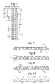
  • Substrates loaded in parts trays 50 generally as outlined are depicted in Figures 7-11, and described below.
  • the loaded parts trays 50 may be placed in the pre-heat oven 20 for a selected period of time depending on the substrate, in the instance of certain prisms, for about one to two hours.
  • a "clean-out run” is made prior to removing the heated parts tray 50 from the oven 20.
  • the clean-out run comprises running a program similar to other pitch buttoning process programs, except it may not involve moving the X-Y stage 22.
  • the purpose of the clean-out run is to clean out old pitch from the pitch dispenser 14 and applicator tip 40.
  • a suitable container should be placed directly beneath the applicator tip 40 to catch any old pitch dispensed.
  • the applicator tip 40 is heated during the clean-out run, and may be cleaned with appropriate materials, e.g., a Q-tip or the like and acetone or another appropriate solvent, to help control or limit pitch tails which might otherwise occur during the buttoning process.
  • a parts tray 50 is removed from the oven 20 and installed on locating or positioning devices, such as pins, posts or pins receiving holes (not shown, but typical), provided on the X-Y stage 22. Suitable means for holding the parts tray 50 in place, e.g., an electromagnetic system or a mechanical system, is actuated.
  • locating or positioning devices such as pins, posts or pins receiving holes (not shown, but typical)
  • Suitable means for holding the parts tray 50 in place e.g., an electromagnetic system or a mechanical system, is actuated.
  • a vertical clearance e.g., approximately 0.17 to 0.26 inch, between the applicator tip 40 at the bottom of the dispensing head 14 and the substrates loaded on the parts tray 50 may be selected.
  • Vertical height adjustment of the applicator tip 40 may be achieved by turning the crank handle 44, but other height adjustment means, such as a stepper motor and belt or screw arrangement may used as well. In the instance of the mechanical crank height adjustment system 44, clockwise is up and counterclockwise is down.
  • the pitch pump (not shown, but which may be coupled to or a component of the hot melt unit 16) should be turned on at the control panel and a selected, appropriate motion architect software should be actuated. Once the motion program is selected, it may be communicated or sent, and actuated. An operator should watch the program run, i.e., the buttons being placed, for at least several minutes. An emergency stop may be provided to halt the program. After the last substrate has been buttoned, the pitch pump should be turned off immediately while the program is allowed to finish. After the program has finished, all X-Y stage motion will stop and the substrates may be removed. The motion program should be dismissed by selecting an appropriate menu command, and the main power switch may be turned off.
  • the pitch button station 12 described herein may have default settings which have been synchronized to work together. These settings, which are intended to be exemplary, will yield a pitch button of approximately 0.3 inches in diameter by 0.12 inches thick, which will adhere to a substrate preheated to approximately 60 degrees centigrade and then cooled slightly (approximately less than 15 minutes). The following exemplary default settings may be varied, but for the exemplary programs or operations set forth herein, should not be changed without explicit prearrangement.
  • stage commands are set forth, explained and listed in the "Compumotor 600 Series Software Reference” (Parker Hannifin Corp. P/N 88-012966-01), which is incorporated herein by reference. Stage programming information is contained in the "Compumotor 600 Series Programer's Guide” (Parker Hannifin Corp. P/N 88-014540-01), which is incorporated herein by reference.
  • Hot melt unit 16 With respect to the hot melt unit 16 and its operational commands, such may be found in the "Slautterback Service Manual” (Slautterback Loose Leaf Binder, Order No. C262711, Model Name KB10,200-230VT500, Schematic Numbers 19610, 034012601, 12-3-97), which are incorporated herein by reference.
  • Each of the noted subroutines defines a particular pitch button pattern which may be varied as desired. Building or combining several of these and/or altering the order in which they are called places a desired overall pitch button pattern on substrates mounted in a parts tray.
  • RS1 defines the jump from the home position to the first dot position (beginning of SR2).
  • SR2 defines the pitch button pattern for the first row of buttons, as shown.
  • SR3 defines the jump from the last button of one substrate in the first row of buttons to the first button of the next substrate in that row, as shown.
  • RS4 defines the jump from the last button of the first row to the first button of the second row of bottons, as shown.
  • SR5 defines the pitch button pattern for the second row of bottons, as shown.
  • SR6 defines the jump from the last button of one substrate in the second row of bottons to the first button of the next substrate in that row, as shown.
  • SR7 defines the jump from the last button of the last row of the buttons in the first row of substrates to the first button of the first row of button on the second row of substrates, as shown.
  • FIG. 7-11 various patterns of loading of optics on parts trays 50, 50' are depicted.
  • a selected program generally of the type set forth in Appendix A, will correspond to the depicted loading; however, custom designed loading patterns and programs are encompassed by the present invention.
  • Each of the Figures provides an elevational sectional view of substrates loaded on a parts tray 50.
  • the parts tray 50 which is intended to representative of such trays, has a plurality of optic receiving rails or supports 51.
  • the loading pattern is to set the optics 52 flush to each other and to the back stop or end of each column, and on the parts tray 50 as depicted in the Figure 7-11.
  • prisms 52 are depicted loaded or positioned on a parts tray 50 in a position wherein pitch buttons 54 are deposited on the hypothenuse of a prism 52 to facilitate polishing the legs in a subsequent part of the manufacturing process.
  • pitch buttons 54 are depicted on the legs of the prisms 52 to enable the subsequent polishing of the hypothenuse.
  • Figure 9 is generally similar, but for a different optic or prism.
  • Figure 10 depicts another prism configuration positioned on a parts tray 50 to receive pitch on the hypothenuse to enable subsequent polishing of the legs
  • Figure 11 depicts patterning and positioning of prisms on a tray 50 to deposit pitch on the legs so the hypotenuse may be polished.
  • Figure 12 depicts a parts tray 50' that does not have optic supporting rails.
  • the loading pattern for this tray 50' is to set the optics flush to each other in both directions and to the back and left sides of the tray 50', with the longer direction (if the otic is rectangular) aligned with the front-back direction of the parts tray 50' and the pitch button station 12.
  • the optic(s) 52 depicted in Figure 12 is a large reference mirror 52'.
  • Alternative embodiments of the pitch button station 12 of the present invention may be configured as desired.
  • a multiple or three-axis (i.e., X, Y, Z axes) positioning stage may be used in place of the X-Y (i.e., dual) stage 22.
  • Interchangeable applicator tips may be used to additionally control, shape or regulate the dispensing of pitch and the size and shape of pitch buttons.
  • the station may include an modified, expanded or relocated staging area, or a staging platform designed to accommodate a particular parts tray 50. Suitable shelving or conveying means may be incorporated, and a freezer or cooler may be adjacent or incorporated for cooling purposes. Storage cabinets or racks may be provided or integrated as well.
  • suitable microprocessor computer and peripheral equipment, including sensors for monitoring the process of the present invention, and/or additional microprocessors, may be incorporated.
  • the microprocessor for example a suitable pc, or microprocessors, may be programed and/or provided with a suitable data storage medium to accomplish blocking of virtually any selected optic or prism, or numbers thereof.

Abstract

The present invention provides a work station (12) and method for applying a blocking material such as pitch or the like to a selected location on a workpiece or workpieces (52), wherein the work station (12) includes an automated blocking material dispenser (14), an X-Y stage (22) for positioning the workpiece(s) (52) and a microprocessor (24), and wherein the method includes the synchronized operation of the X-Y stage (22) and the dispenser (14) under control of the microprocessor (24) to deposit a selected amount and shape of the blocking material in a selected location or locations on a workpiece or workpieces (52) with a high degree of repeatability in a short cycle time.

Description

BACKGROUND
The present invention relates to manufacturing equipment and methods, particularly equipment and procedures which may be involved in the making of optical items, such as polarizing beam splitter ("PBS") prism assemblies, for use in, for example, interferometers and other optical products. More particularly, the present invention relates to blocking technology, i.e., holding or supporting technology, for holding prisms or other optical workpieces or items in a selected position for performing work on them efficiently, with precision, and without inducing strain that could deform them.
Blocking or supporting optical elements is known in the manufacture and treatment of high precision optics and optical items such as prisms, mirrors, lenses, windows and the like. One method of blocking may involve a blocking tool and the use of pitch "buttons." The buttons comprise deposits of blocking pitch, usually in the form of small discs, which are applied to a surface or surfaces of the optic being blocked or supported. The pitch button size, form factor, location on the optic surface and adherent qualities are variables which may affect the blocking process.
Currently, pitch button blocking is done by hand, using trained experts who apply a selected number of buttons, of a selected size, to a selected location or locations on a workpiece. The process is very time consuming and requires highly trained operators and experts, and thus is currently labor intensive. Even using trained technicians, it typically takes one to two days to "button" a set of prisms using the traditional, known methods.
Another problem is that, although experts are used, the consistency of the button size and layout location could be improved. In fact, the button-to-button volume variation using traditional methods is typically greater than 60%.
Clearly, there is need for an automated apparatus and method of dispensing pitch buttons to reduce the labor involved, to reduce the need for "expert" technicians, to shorten the pitch buttoning cycle time and to increase the consistency and repeatability of the pitch button size and layout location.
SUMMARY
The present invention provides an apparatus or system and method for dispensing or applying a selected amount of supporting or holding material to a selected location on a workpiece.
In one embodiment, the present invention provides a work station and method for applying a blocking material, such as pitch or the like, to a selected location on a workpiece, wherein the work station includes an automated blocking material dispenser, a positioning stage for positioning the workpiece and a microprocessor, and wherein the method includes the synchronized and complimentary operation of the positioning stage and the dispenser under control of the microprocessor to deposit a selected amount and shape of the blocking material in a selected location or locations on a workpiece or workpieces with a high degree of repeatability in a short cycle time.
In another embodiment, the present invention provides a work station comprising an automated pitch dispenser for dispensing or applying one or more pitch buttons to a workpiece or workpieces, and a positioning stage for positioning the workpiece(s), wherein the dispenser and positioning stage are coordinately operated and controlled by a suitable computer or microprocessor and software. The work station may include appropriate peripheral devices and apparatus such as a preheating oven, sensing or process monitoring devices, and workpiece carriers and/or tool holders.
In one embodiment, the method of use or operation of the pitch button station of the present invention comprises the positioning stage, for example an X-Y stage, moving or positioning a workpiece or workpieces, such as pre-heated optics, relative to a pitch dispenser, and the dispenser depositing pitch buttons on the positioned workpiece(s). In this embodiment, wherein the pitch dispenser and the X-Y stage are controlled by a computer and appropriate software or program(s), the buttons are positioned at precise, selected positions, in a precise selected size, in a very short cycle time, and with a high degree of repeatability.
An advantage of the present invention is that it speeds the "buttoning" process from the typical one to two days to button a set of prisms using known methods to about an hour.
Another advantage of the present invention is that button volume variants are expected to decrease to less than 8%. This is advantageous because it creates greater process consistency, resulting in reduced polishing time and better flatness control of the optics.
Advantageously, the pitch button apparatus and method of the present invention will help reduce manufacturing costs and new product introduction costs by using a continuous process. It will further the goal of developing manufacturing processes which enable fast response to market needs. It will facilitate the development of high and consistent yields of optics, reduce process variability, and provide for the easier, more accurate monitoring and accumulation of cost and quality information and management.
Additional advantages of automating pitch button blocking in accordance with the present invention include shortening lead time, removing the need for as many experts in the buttoning process, allowing achievement of better flatness control, increasing yields through greater blocking process consistency and supporting production goals, particularly as regards certain optics, such as 1 inch, 2 inch x 1 inch, and 4 inch x 1 inch prisms, from a common blank and fabrication process. In particular, the apparatus and method of the present invention saves money and provides for increased production levels.
In one embodiment, the pitch button dispensing station of the present invention is a customized work station which automatically deposits pitch buttons on prisms.
The pitch button dispensing station system or assembly of the present invention may be incorporated conveniently into current manufacturing lines and/or facilities, and it may be adapted or configured to improve and/or conform to a particular material flow.
Other features and advantages of the automated pitch button dispensing apparatus and method of the present invention will become more fully apparent and understood with reference to the following description and appended drawings and claims.
BRIEF DESCRIPTION OF THE DRAWINGS
Figure I is a front elevational view of one embodiment of the pitch button dispensing station in accordance with the present invention.
Figure 2 is a top plan view of the embodiment depicted in Figure 1.
Figure 3 is a side elevational view, partially in cross-section, of the dispenser head of the embodiment depicted in Figure 1.
Figure 4 is a front elevational view, partially in cross-section, of the dispenser head.
Figure 5 is a front elevational view, partially in cross-section, of the embodiment depicted is Figure 1.
Figure 6 depicts the one operational effect or result of the pitch button station and method of the present invention.
Figure 7 is a front elevational of another operational effect or result of the pitch button station and method of the present invention.
Figure 8 is a front elevational of another operational effect or result of the pitch button station and method of the present invention.
Figure 9 depicts a front elevational of another operational effect or result of the pitch button station and method of the present invention.
Figure 10 depicts a front elevational of another operational effect or result of the pitch button station and method of the present invention.
Figure 11 depicts a front elevational of another operational effect or result of the pitch button station and method of the present invention.
Figure 12 is a top plan view of a parts tray.
DETAILED DESCRIPTION
The accompanying Figures and this description depict and describe embodiments of a automated work station and method for applying a blocking material, such as pitch or the like, to a selected location on a workpiece, for example, an optic, wherein the work station includes an automated blocking material dispenser, a positioning stage for positioning the workpiece and a microprocessor, and wherein the method includes the synchronized and complimentary operation of the positioning stage and the dispenser under control of the microprocessor to deposit a selected amount and shape of the blocking material in a selected location or locations on a workpiece. As used herein the term "station" is intended to encompass an area or location of operations, and apparatus at or in the area or location for performing operations. As used herein the term "pitch" is intended to encompass any material suitable for use in blocking, i.e., holding and supporting, operations, including viscous substances typically obtained as a residue in the distillation of organic materials, bituminous substances, resinous substances, artificial mixtures resembling resinous or bituminous pitches and the like. With regard to means and devices for fastening, mounting, coupling, attaching or connecting components of the present invention to form the apparatus and system as a whole, unless specifically described otherwise, such means and devices are intended to encompass conventional fasteners such as machine screws, nut and bolt type connectors, snap rings, clamps such as hose clamps, screw clamps and the like, rivets, toggles, pins and the like. Components may also be connected by adhesives, glues, welding, ultrasonic welding, and friction fitting or deformation, if appropriate. Other fastening or attachment devices or methods such as soldering may be used as well, particularly with regard to the electrical system of the apparatus. All components of the electrical system and/or wiring harness or connections of the present invention may be conventionally, operably linked conventional commercially available components, unless otherwise indicated, including electrical components (e.g., switches, fuses, lights, connectors, etc.) and circuitry, wires, soldered connections, inputs, chips, boards and display and/or control system components.
Generally, unless specifically otherwise disclosed or taught, materials for making, assembling or coupling components of the present invention may be selected from appropriate materials such as metal, metallic alloys, ceramics, plastics, glasses and the like. Appropriate manufacturing or production methods including casting, pressing, extruding, molding and machining may be used.
Any references to front and back, right and left, top and bottom, and upper and lower are intended for convenience of description, not to limit the present invention or its components to any one positional or spacial orientation.
This detailed description is intended to be read and understood in conjunction with Appendix A which is incorporated herein by reference. Appendix A provides one sequence of operations of the method of the present invention.
Referring then to the Figures, particularly Figure 1, the pitch button dispensing and applying station or apparatus 12 in accordance with the present invention comprises a pitch button applicator 14, a hot melt unit 16, a control panel 18, a pre-heating oven 20, an X-Y stage 22, a computer 24, incorporating and/or having access to a suitable data storage medium, and a monitor 26. An exhaust system 28, including a hood and conduit coupled to a suitable flow inducing device (not shown), may be provided to handle any heat and fumes produced during use of the apparatus 12. As shown in Figure 1, the components of the apparatus 12 may be mounted on a suitable frame 30, and the frame 30 may be provided with an appropriate number of wheels or casters 32.
Referring to Figure 2, an input keyboard 36 may be suitably located adjacent the monitor 26 to provide convenient input or control of the process of the present invention.
Additional details of the applicator 14, particularly the pitch button dispensing head 38 thereof, are depicted in Figures 3 and 4. The pitch button dispensing head 38 includes an applicator tip 40 coupled by a suitable conduit 42 to a pitch supply, typically in the hot melt unit 16, a height adjustment crank 44, and the exhaust hood 46 which is coupled to the exhaust system 28.
Referring to Figure 5, the generally spaced, parallel relationship between the X-Y stage 22 and the applicator 14, particularly the applicator tip 40, is depicted, along with a loaded parts tray 50, the tray 50 being depicted as loaded or containing a plurality of one-inch prisms 52, each "buttoned" with pitch buttons 54.
Operation
In use, the pitch button blocking station 12 of the present invention is used by turning on the main power switch, which may be suitably located on the front control panel 18, along with other controls, inputs and suitable operational indicators, such as "power-on" indicators or lights. The operator should check that the power is on to the pitch melt unit 16 and to the oven 20. The oven 20 and pitch in the hot melt unit 16 should be allowed to heat for approximately 30 minutes before placing any substrates (i.e., workpieces) into the oven 20. Next, substrates, e.g., prisms, mirrors or other optics, are loaded on to a parts tray 50. A layer of photocopy paper (not shown) may be used between the substrates on the parts tray 50 to avoid scratching the substrates and to protect the parts tray 50 from pitch. One general loading pattern for substrates is flush to the left side and rear of the parts tray 50, but other arrangements may be used. Typically, a parts tray 50 has a front portion with an edge or side wall with a bar containing adjustable set screw stops for positioning and securing workpieces. Substrates loaded in parts trays 50 generally as outlined are depicted in Figures 7-11, and described below. The loaded parts trays 50 may be placed in the pre-heat oven 20 for a selected period of time depending on the substrate, in the instance of certain prisms, for about one to two hours.
Next, a "clean-out run" is made prior to removing the heated parts tray 50 from the oven 20. The clean-out run comprises running a program similar to other pitch buttoning process programs, except it may not involve moving the X-Y stage 22. The purpose of the clean-out run is to clean out old pitch from the pitch dispenser 14 and applicator tip 40. A suitable container should be placed directly beneath the applicator tip 40 to catch any old pitch dispensed. The applicator tip 40 is heated during the clean-out run, and may be cleaned with appropriate materials, e.g., a Q-tip or the like and acetone or another appropriate solvent, to help control or limit pitch tails which might otherwise occur during the buttoning process.
A parts tray 50 is removed from the oven 20 and installed on locating or positioning devices, such as pins, posts or pins receiving holes (not shown, but typical), provided on the X-Y stage 22. Suitable means for holding the parts tray 50 in place, e.g., an electromagnetic system or a mechanical system, is actuated.
Next, a vertical clearance, e.g., approximately 0.17 to 0.26 inch, between the applicator tip 40 at the bottom of the dispensing head 14 and the substrates loaded on the parts tray 50 may be selected. Vertical height adjustment of the applicator tip 40 may be achieved by turning the crank handle 44, but other height adjustment means, such as a stepper motor and belt or screw arrangement may used as well. In the instance of the mechanical crank height adjustment system 44, clockwise is up and counterclockwise is down.
Next, the pitch pump (not shown, but which may be coupled to or a component of the hot melt unit 16) should be turned on at the control panel and a selected, appropriate motion architect software should be actuated. Once the motion program is selected, it may be communicated or sent, and actuated. An operator should watch the program run, i.e., the buttons being placed, for at least several minutes. An emergency stop may be provided to halt the program. After the last substrate has been buttoned, the pitch pump should be turned off immediately while the program is allowed to finish. After the program has finished, all X-Y stage motion will stop and the substrates may be removed. The motion program should be dismissed by selecting an appropriate menu command, and the main power switch may be turned off.
The pitch button station 12 described herein may have default settings which have been synchronized to work together. These settings, which are intended to be exemplary, will yield a pitch button of approximately 0.3 inches in diameter by 0.12 inches thick, which will adhere to a substrate preheated to approximately 60 degrees centigrade and then cooled slightly (approximately less than 15 minutes). The following exemplary default settings may be varied, but for the exemplary programs or operations set forth herein, should not be changed without explicit prearrangement.
Tank 220 degrees F
Hose 230 degrees F
Head 240 degrees F
Oven 60 Degrees C
Pump 2 1/4 full turns from a closed position
Scale 125000 steps per linear inch
Varl=0 set variable I to 0
Var2=0.2 set variable 2 to 0.2
Var3=0.11 set variable 3 to 0.1
Hom5,5 set stage velocity to 5
With respect to the X-Y stage 22, the stage commands are set forth, explained and listed in the "Compumotor 600 Series Software Reference" (Parker Hannifin Corp. P/N 88-012966-01), which is incorporated herein by reference. Stage programming information is contained in the "Compumotor 600 Series Programer's Guide" (Parker Hannifin Corp. P/N 88-014540-01), which is incorporated herein by reference.
With respect to the hot melt unit 16 and its operational commands, such may be found in the "Slautterback Service Manual" (Slautterback Loose Leaf Binder, Order No. C262711, Model Name KB10,200-230VT500, Schematic Numbers 19610, 034012601, 12-3-97), which are incorporated herein by reference.
The way one program works is set forth in Appendix A. Each of the noted subroutines defines a particular pitch button pattern which may be varied as desired. Building or combining several of these and/or altering the order in which they are called places a desired overall pitch button pattern on substrates mounted in a parts tray. For instance, referring to Figure 6, a substantially representational depiction, RS1 defines the jump from the home position to the first dot position (beginning of SR2). SR2 defines the pitch button pattern for the first row of buttons, as shown. SR3 defines the jump from the last button of one substrate in the first row of buttons to the first button of the next substrate in that row, as shown. RS4 defines the jump from the last button of the first row to the first button of the second row of bottons, as shown. SR5 defines the pitch button pattern for the second row of bottons, as shown. SR6 defines the jump from the last button of one substrate in the second row of bottons to the first button of the next substrate in that row, as shown. SR7 defines the jump from the last button of the last row of the buttons in the first row of substrates to the first button of the first row of button on the second row of substrates, as shown.
Referring to Figures 7-11, various patterns of loading of optics on parts trays 50, 50' are depicted. A selected program, generally of the type set forth in Appendix A, will correspond to the depicted loading; however, custom designed loading patterns and programs are encompassed by the present invention. Each of the Figures provides an elevational sectional view of substrates loaded on a parts tray 50. The parts tray 50, which is intended to representative of such trays, has a plurality of optic receiving rails or supports 51. Generally, for this type of tray 50, the loading pattern is to set the optics 52 flush to each other and to the back stop or end of each column, and on the parts tray 50 as depicted in the Figure 7-11. In Figure 7, prisms 52 are depicted loaded or positioned on a parts tray 50 in a position wherein pitch buttons 54 are deposited on the hypothenuse of a prism 52 to facilitate polishing the legs in a subsequent part of the manufacturing process. In Figure 8, a loading pattern similar to that depicted in Figure 7 is shown, but pitch buttons 54 are depicted on the legs of the prisms 52 to enable the subsequent polishing of the hypothenuse. Figure 9 is generally similar, but for a different optic or prism. Figure 10 depicts another prism configuration positioned on a parts tray 50 to receive pitch on the hypothenuse to enable subsequent polishing of the legs, and Figure 11 depicts patterning and positioning of prisms on a tray 50 to deposit pitch on the legs so the hypotenuse may be polished.
Figure 12 depicts a parts tray 50' that does not have optic supporting rails. The loading pattern for this tray 50' is to set the optics flush to each other in both directions and to the back and left sides of the tray 50', with the longer direction (if the otic is rectangular) aligned with the front-back direction of the parts tray 50' and the pitch button station 12. The optic(s) 52 depicted in Figure 12 is a large reference mirror 52'.
Alternative Embodiments
Alternative embodiments of the pitch button station 12 of the present invention may be configured as desired. For example, a multiple or three-axis (i.e., X, Y, Z axes) positioning stage may be used in place of the X-Y (i.e., dual) stage 22. Interchangeable applicator tips may used to additionally control, shape or regulate the dispensing of pitch and the size and shape of pitch buttons. The station may include an modified, expanded or relocated staging area, or a staging platform designed to accommodate a particular parts tray 50. Suitable shelving or conveying means may be incorporated, and a freezer or cooler may be adjacent or incorporated for cooling purposes. Storage cabinets or racks may be provided or integrated as well. In some embodiments of the present invention, suitable microprocessor, computer and peripheral equipment, including sensors for monitoring the process of the present invention, and/or additional microprocessors, may be incorporated. The microprocessor, for example a suitable pc, or microprocessors, may be programed and/or provided with a suitable data storage medium to accomplish blocking of virtually any selected optic or prism, or numbers thereof.
The present invention may be embodied in other specific forms and/or steps without departing from the essential spirit or attributes thereof. The described embodiment should be considered in all respects as illustrative, not restrictive.
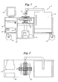
Figure 00080001
Figure 00090001
Figure 00100001
Figure 00110001
Figure 00120001

Claims (12)

  1. An apparatus (12) for applying a material to a workpiece (52) at a selected location on the workpiece (52), the apparatus (12) comprising an automated material dispenser (14), a positioning stage (22) for positioning the workpiece, and a microprocessor (24) for controlling the dispenser (14) and positioning stage (22).
  2. The apparatus according to claim 1, wherein the positioning stage (22) is an X-Y stage.
  3. The apparatus according to claim 1, further comprising a height adjustor (44) for selecting a generally vertical distance between the dispenser (14) and the positioning stage (22).
  4. The apparatus according to claim 3, wherein the material dispenser (14) comprises an applicator (44) and a hot melt unit (16).
  5. The apparatus according to claim 4, wherein the workpiece (52) is an optic.
  6. An automated work station (12) for applying a blocking material, such as pitch, at a selected location on a selected number of workpieces (52), wherein the work station (12) comprises a blocking material dispenser (14), a movable positioning stage (22) for positioning the workpieces, a processing unit (24) for controlling the movement of the positioning stage (22) and the dispensing of the dispenser (14), and a data storage medium operably incorporated with and accessible by the processing unit (24), wherein the data storage medium has a program stored on it, and wherein in the program is configured to cause the processing unit (24) to synchronize the movement of the positioning stage (22) and the dispensing of the dispenser (14).
  7. The automated work station (12) accoding to claim 6, wherein the positioning stage (22) is a two axis stage.
  8. A data storage medium for use with a processing unit (24) that controls a dispenser (14) and an X-Y stage (22), wherein the data storage medium has a program stored on it that causes synchronized dispensing from the dispenser (14) and movement of the X-Y stage (22).
  9. The data storgae medium of claim 8, wherein the dispenser (14) dispenses a selected amount of material.
  10. A method for applying a material to a workpiece (52) at a selected location on the'workpiece (52), the method comprising the steps of positioning the workpiece (52) relative to a material dispenser (14) and dispensing an amount of material onto the workpiece (52), said positioning and dispensing occuring under control of a microprocessor (24).
  11. The method according to claim 10, wherein the positioning and dispensing are sychronized.
  12. The method according to claim 11, wherein the positioning is accomplished by a positioning stage (22) having two axes of motion.
EP01108210A 2000-06-01 2001-03-30 Automated pitch button dispensing station and method Withdrawn EP1160017A3 (en)

Applications Claiming Priority (2)

Application Number Priority Date Filing Date Title
US586180 2000-06-01
US09/586,180 US6692573B1 (en) 2000-06-01 2000-06-01 Automated pitch button dispensing station and method

Publications (2)

Publication Number Publication Date
EP1160017A2 true EP1160017A2 (en) 2001-12-05
EP1160017A3 EP1160017A3 (en) 2006-12-06

Family

ID=24344635

Family Applications (1)

Application Number Title Priority Date Filing Date
EP01108210A Withdrawn EP1160017A3 (en) 2000-06-01 2001-03-30 Automated pitch button dispensing station and method

Country Status (3)

Country Link
US (1) US6692573B1 (en)
EP (1) EP1160017A3 (en)
JP (1) JP2002028831A (en)

Cited By (2)

* Cited by examiner, † Cited by third party
Publication number Priority date Publication date Assignee Title
CN103599871A (en) * 2013-10-25 2014-02-26 深圳市恒睿智达科技有限公司 Separated type dispensing mechanism
CN104785412A (en) * 2015-04-15 2015-07-22 夏治政 Dispensing device of camera

Families Citing this family (9)

* Cited by examiner, † Cited by third party
Publication number Priority date Publication date Assignee Title
US20070084523A1 (en) * 2005-09-23 2007-04-19 Angstrom Power Incorporated Systems and methods for replenishing fuel-cell-powered portable devices
CN100560222C (en) * 2006-06-16 2009-11-18 鸿富锦精密工业(深圳)有限公司 Spin coating dispensing device and dispensing method
JP4653028B2 (en) * 2006-06-30 2011-03-16 三菱エンジニアリングプラスチックス株式会社 Polycarbonate resin composition and infrared laser filter
CN102200566A (en) * 2010-03-22 2011-09-28 鸿富锦精密工业(深圳)有限公司 Key testing device
JP5968418B2 (en) * 2011-03-21 2016-08-10 ローレンス リバモア ナショナル セキュリティー, エルエルシー Convergent polishing method and convergent polishing system
CN103084302A (en) * 2011-11-04 2013-05-08 深圳市腾盛工业设备有限公司 Quantitative dispensing device
CN105597991B (en) * 2014-11-21 2018-09-04 中国科学院沈阳自动化研究所 A kind of automatic glue spreaders
CN110907883B (en) * 2019-10-25 2023-04-14 湖北省计量测试技术研究院 A measurement supervision method and system for an automatic verification system of an electric energy meter
CN113427254B (en) * 2021-07-13 2022-08-05 东莞明丰五金制品有限公司 Automatic assembling machine for watch clamp spring

Family Cites Families (9)

* Cited by examiner, † Cited by third party
Publication number Priority date Publication date Assignee Title
US4572103A (en) * 1984-12-20 1986-02-25 Engel Harold J Solder paste dispenser for SMD circuit boards
US4661368A (en) * 1985-09-18 1987-04-28 Universal Instruments Corporation Surface locating and dispensed dosage sensing method and apparatus
JPS6481294A (en) * 1987-09-22 1989-03-27 Juki Kk Method and apparatus for forming thick-film circuit
US5121329A (en) * 1989-10-30 1992-06-09 Stratasys, Inc. Apparatus and method for creating three-dimensional objects
US5110615A (en) * 1990-01-31 1992-05-05 Asymptotic Technologies, Inc. Method for dispensing viscous materials a constant height above a workpiece surface
JP2597778B2 (en) * 1991-01-03 1997-04-09 ストラタシイス,インコーポレイテッド Three-dimensional object assembling system and assembling method
US5534101A (en) * 1994-03-02 1996-07-09 Telecommunication Research Laboratories Method and apparatus for making optical components by direct dispensing of curable liquid
JP3697315B2 (en) * 1996-05-13 2005-09-21 松下電器産業株式会社 Adhesive applicator
US6401001B1 (en) * 1999-07-22 2002-06-04 Nanotek Instruments, Inc. Layer manufacturing using deposition of fused droplets

Cited By (2)

* Cited by examiner, † Cited by third party
Publication number Priority date Publication date Assignee Title
CN103599871A (en) * 2013-10-25 2014-02-26 深圳市恒睿智达科技有限公司 Separated type dispensing mechanism
CN104785412A (en) * 2015-04-15 2015-07-22 夏治政 Dispensing device of camera

Also Published As

Publication number Publication date
JP2002028831A (en) 2002-01-29
US6692573B1 (en) 2004-02-17
EP1160017A3 (en) 2006-12-06

Similar Documents

Publication Publication Date Title
US6692573B1 (en) Automated pitch button dispensing station and method
US5036582A (en) Parts mounting machine
US7142936B2 (en) NC data management apparatus and method
US20220161544A1 (en) Printing parameter acquisition device and printing parameter acquisition method
JP7349608B2 (en) Production planning method, production planning device, and production planning program
JP7450137B2 (en) Production plan display method, production plan display system, and production plan display program
JP2000059090A (en) Method and apparatus for managing setup timing in mounting machine
US7543259B2 (en) Method and device for deciding support portion position in a backup device
KR960009881B1 (en) Processing of magnetic head flexures with slider elements
KR20120059595A (en) Operating device
DE3111809A1 (en) METHOD AND DEVICE FOR MACHINE SOLDERING WORKPIECES
JPH09312494A (en) Mounting machine parts supply method
CN108014964A (en) It is suitable for the coating head of the profile at face plate edge or other cloth member edges to be coated
JP7762895B2 (en) Maintenance support system, maintenance support method, and maintenance support program
JP2518633B2 (en) Assembly equipment
JP7442035B2 (en) Production plan display method, production plan display system, and production plan display program
JP4796462B2 (en) Component assembly assignment method, component assembly assignment device, and mounter for mounting machine
JP2008270337A (en) MOUNTING BOARD MANUFACTURING DEVICE, METHOD FOR OPTIMIZING THE SAME, AND PROGRAM FOR MOUNTING BOARD MANUFACTURING DEVICE
CN2086499U (en) Auomtatic tin-spraying machine
CN111678604A (en) Temperature field monitoring device for selective laser melting forming process
US20060005378A1 (en) Apparatus and method for demounting and mounting an integrated circuit
CN216880075U (en) Die bonding equipment
CN222220123U (en) Double station glue spraying device
CN104669368B (en) A kind of automatic positioning tooling for hypotenuse sheet fabrication and processing method thereof
JP2004066372A (en) Cell line production method and production method

Legal Events

Date Code Title Description
PUAI Public reference made under article 153(3) epc to a published international application that has entered the european phase

Free format text: ORIGINAL CODE: 0009012

AK Designated contracting states

Kind code of ref document: A2

Designated state(s): AT BE CH CY DE DK ES FI FR GB GR IE IT LI LU MC NL PT SE TR

AX Request for extension of the european patent

Free format text: AL;LT;LV;MK;RO;SI

PUAL Search report despatched

Free format text: ORIGINAL CODE: 0009013

AK Designated contracting states

Kind code of ref document: A3

Designated state(s): AT BE CH CY DE DK ES FI FR GB GR IE IT LI LU MC NL PT SE TR

AX Request for extension of the european patent

Extension state: AL LT LV MK RO SI

STAA Information on the status of an ep patent application or granted ep patent

Free format text: STATUS: THE APPLICATION HAS BEEN WITHDRAWN

18W Application withdrawn

Effective date: 20061205