EP1159996A2 - Two-phase flow separator - Google Patents
Two-phase flow separator Download PDFInfo
- Publication number
- EP1159996A2 EP1159996A2 EP01304453A EP01304453A EP1159996A2 EP 1159996 A2 EP1159996 A2 EP 1159996A2 EP 01304453 A EP01304453 A EP 01304453A EP 01304453 A EP01304453 A EP 01304453A EP 1159996 A2 EP1159996 A2 EP 1159996A2
- Authority
- EP
- European Patent Office
- Prior art keywords
- foam
- filter
- liquid
- separation chamber
- phase
- Prior art date
- Legal status (The legal status is an assumption and is not a legal conclusion. Google has not performed a legal analysis and makes no representation as to the accuracy of the status listed.)
- Granted
Links
- 230000005514 two-phase flow Effects 0.000 title claims description 10
- 239000006260 foam Substances 0.000 claims abstract description 90
- 239000007788 liquid Substances 0.000 claims abstract description 65
- 238000000034 method Methods 0.000 claims abstract description 12
- 239000000203 mixture Substances 0.000 claims abstract description 5
- 239000011148 porous material Substances 0.000 claims description 14
- 238000000926 separation method Methods 0.000 claims description 13
- 239000000463 material Substances 0.000 claims description 10
- 238000009736 wetting Methods 0.000 claims description 5
- 239000012530 fluid Substances 0.000 description 21
- 230000001276 controlling effect Effects 0.000 description 4
- 238000010586 diagram Methods 0.000 description 4
- 238000007641 inkjet printing Methods 0.000 description 2
- 230000004048 modification Effects 0.000 description 2
- 238000012986 modification Methods 0.000 description 2
- 238000007639 printing Methods 0.000 description 2
- 238000009825 accumulation Methods 0.000 description 1
- 230000015556 catabolic process Effects 0.000 description 1
- 238000005336 cracking Methods 0.000 description 1
- 230000000694 effects Effects 0.000 description 1
- 238000005516 engineering process Methods 0.000 description 1
- 238000005187 foaming Methods 0.000 description 1
- 230000037406 food intake Effects 0.000 description 1
- 238000009472 formulation Methods 0.000 description 1
- 230000005484 gravity Effects 0.000 description 1
- 238000004519 manufacturing process Methods 0.000 description 1
- 239000003595 mist Substances 0.000 description 1
- 230000001105 regulatory effect Effects 0.000 description 1
- 239000000126 substance Substances 0.000 description 1
- 239000004094 surface-active agent Substances 0.000 description 1
Images


Classifications
-
- B—PERFORMING OPERATIONS; TRANSPORTING
- B41—PRINTING; LINING MACHINES; TYPEWRITERS; STAMPS
- B41J—TYPEWRITERS; SELECTIVE PRINTING MECHANISMS, i.e. MECHANISMS PRINTING OTHERWISE THAN FROM A FORME; CORRECTION OF TYPOGRAPHICAL ERRORS
- B41J2/00—Typewriters or selective printing mechanisms characterised by the printing or marking process for which they are designed
- B41J2/005—Typewriters or selective printing mechanisms characterised by the printing or marking process for which they are designed characterised by bringing liquid or particles selectively into contact with a printing material
- B41J2/01—Ink jet
- B41J2/17—Ink jet characterised by ink handling
- B41J2/19—Ink jet characterised by ink handling for removing air bubbles
-
- B—PERFORMING OPERATIONS; TRANSPORTING
- B01—PHYSICAL OR CHEMICAL PROCESSES OR APPARATUS IN GENERAL
- B01D—SEPARATION
- B01D19/00—Degasification of liquids
- B01D19/0031—Degasification of liquids by filtration
-
- B—PERFORMING OPERATIONS; TRANSPORTING
- B01—PHYSICAL OR CHEMICAL PROCESSES OR APPARATUS IN GENERAL
- B01D—SEPARATION
- B01D19/00—Degasification of liquids
- B01D19/0063—Regulation, control including valves and floats
-
- B—PERFORMING OPERATIONS; TRANSPORTING
- B41—PRINTING; LINING MACHINES; TYPEWRITERS; STAMPS
- B41J—TYPEWRITERS; SELECTIVE PRINTING MECHANISMS, i.e. MECHANISMS PRINTING OTHERWISE THAN FROM A FORME; CORRECTION OF TYPOGRAPHICAL ERRORS
- B41J2/00—Typewriters or selective printing mechanisms characterised by the printing or marking process for which they are designed
- B41J2/005—Typewriters or selective printing mechanisms characterised by the printing or marking process for which they are designed characterised by bringing liquid or particles selectively into contact with a printing material
- B41J2/01—Ink jet
- B41J2/17—Ink jet characterised by ink handling
- B41J2/175—Ink supply systems ; Circuit parts therefor
- B41J2/17563—Ink filters
Definitions
- the present invention relates to the separation of foam into liquid and air and more particularly to the control of the separating the liquid and gas phase of foam.
- Foam consists of a large number of air bubbles having thin walls of liquid.
- the presence of surfactants in the liquid causes the liquid to resist draining out of the bubble walls.
- the surface tension of the liquid films resists the rupturing of the walls.
- the liquid will slowly drain from the bubble wall until it becomes sufficiently thin that the bubble walls become brittle and rupture.
- Foam is created in continuous ink jet fluid systems due to the fact that not all ink drops are used for printing.
- the unused ink drops are returned to the fluid system under vacuum through a catcher.
- the ink and air are mixed at the catcher and in the fluid lines which return the two phase flow (foam) to the ink supply tank.
- the foam can build up in the ink supply tank and eventually be evacuated into the vacuum system. Damage can then occur to the vacuum system.
- Thermal defoamers heat the fluid above a critical temperature at which drainage of the fluid from the bubble walls increases dramatically. In ink jet systems, as well as other systems, the temperatures required can cause unacceptable break down of the fluid.
- the present invention provides an improved mechanical means of separating the liquid and gas phases of foam.
- the two phase flow separator of the present invention can be applied for use in any field which requires the separation of foam into liquid and air.
- an apparatus for separating the liquid and gaseous components of a foamy mixture.
- the apparatus comprises a filter means through which the liquid portion of the foam can pass and through which the gaseous component cannot pass, unless a pressure differential across the filter exceeds the bubble point of the filter.
- First means are provided to supply the foam to a first side of the filter means.
- Additional means are provided to remove the liquid component of the foam from the second side of the filter, and the gaseous component of the foam from the first side of the filter.
- a pressure differential is established between the two sides of the filter to cause the liquid component of the foam to pass through the filter; but the pressure differential across the filter is prevented from exceeding the bubble point of the filter to prevent the gaseous component of the foam from passing through the filter.
- Fig. 1 is a prior art schematic block diagram of a portion of a continuous ink jet fluid system showing subsystems involved in the production and reduction of foam in the ink tank;
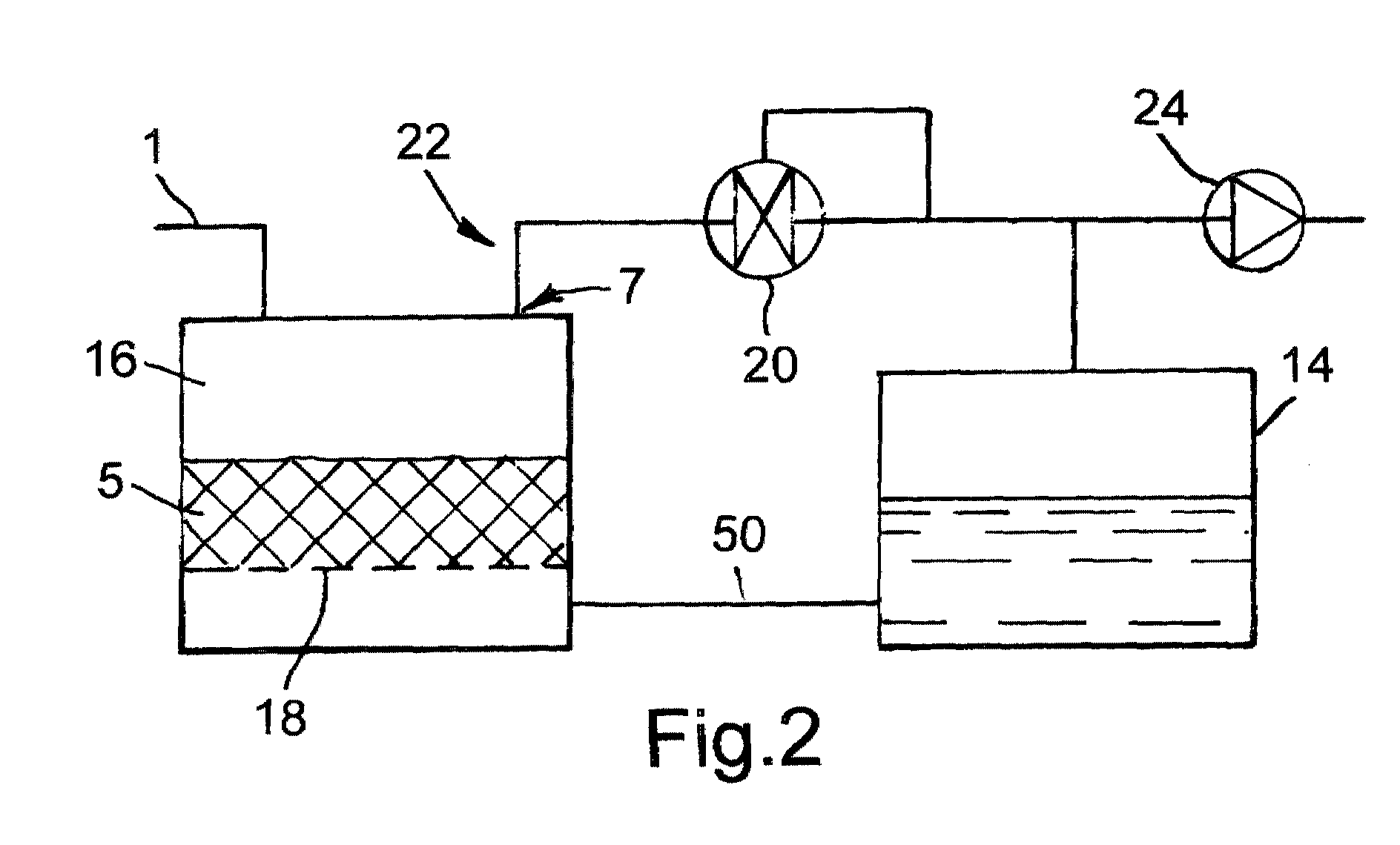
- Fig. 2 is a schematic block diagram showing a modification of the block diagram in Fig. 1 to include a two phase flow separating device;
- Fig. 3 illustrates how the foam is separated into a gas and liquid
- Figs. 4, 5, 6 and 7 are fluid system schematics showing the use of other configurations of fluid system components to maintain a pressure differential across the two phase flow separation screen.
- FIG. 10 there are illustrated schematic block diagrams 10 of a portion of a fluid system in which foam is entering the system.
- the foam can be drawn into this portion of the fluid system by vacuum as shown in Figs. 1, 2 and 4; or pumped in as shown in Figs. 6 and 7.
- Foam is created in continuous ink jet fluid systems due to the fact that not all ink drops are used for printing.
- the unused ink drops are returned to the fluid system under vacuum through a catcher.
- the ink and air are mixed at the catcher and in the fluid lines which return the two phase flow (foam) to the ink supply tank 14, or, in Fig. 1, through the foam inlet port 1.
- foam is reduced by controlling the way in which fluid is returned into the tank. This is accomplished by means of an entrance chamber, a ramp for the ink to flow down, and baffles to protect the vacuum port. Foam buildup is reduced, helping to protect the vacuum pump.
- foam reducing features there are certain ink system situations which can produce foam build up and ingestion of foam into the vacuum pump.
- Fig. 2 The method by which the present invention protects the vacuum pump and eliminates foam is shown in Fig. 2.
- the foam enters in the two phase flow separation chamber 16 though the foam inlet port 1.
- the foam then comes into contact with the filter 18.
- Fig. 3 illustrates how such a filter or any other material with one or more pores can be used as a two phase flow separator.
- a second path 22 is provided to remove the non-liquid part of the foam, i.e., the air or gas.
- the air removal port 7 from the foam reducing chamber 16 is preferably located away from the foam inlet port 1 through which foam enters the chamber to prevent foam from being sucked out the air removal port. Baffles (not shown) may also be employed to isolate the air removal port from the foam.
- This air removal port 22 is normally connected to some vacuum source 24. The vacuum source 24 not only serves to remove the air from the foam reducing chamber but it also maintains the vacuum in the chamber to pull the foamy liquid 50 into the chamber.
- a pressure difference must be maintained across the filter 18.
- One method for maintaining the pressure differential across the filter is the use of a differential vacuum regulator 20, as shown in Fig. 2.
- One such valve is a Fisher type Y611 valve.
- the regulator means in such valves varies the flow of air through the valve to produce the desired pressure differential.
- the use of a single vacuum source with a differential pressure regulating valve allows the vacuum level in the foam reducing chamber to be varied as needed for different operating conditions while still maintaining the desired pressure differential across the filter.
- Another method of maintaining a pressure differential across the filter is by the use of one or more check valves in the place of the differential pressure regulator 20.
- the check valves need to have a cracking pressure below the bubble point of the filter material and be able to pass the maximum amount of required air or gas without creating an unacceptable amount of pressure drop.
- An alternative embodiment rather than using a regulator valve to reduce the vacuum level on the air side of the filter, provides means to increase the vacuum on the liquid side of the filter. This might be done by means of an additional pump 26 to draw air out of the ink tank, with appropriate regulation means 20, as in Fig. 4. This could also be achieved by means of a liquid pump 27 between the liquid side of the filter and the ink tank, again with appropriate regulation means 20, as in Fig. 5. These options, while requiring the additional costs associated with the required pumps, eliminate the need for a regulator valve in the air line.
- a liquid pump to pump the foamy mixture into the foam reducing chamber.
- Figs. 6 and 7 illustrate two embodiments which are appropriate for such systems.
- the embodiment in Fig. 6 restricts the flow of air out of the foam reducing chamber 16, building up pressure on the foam and air side of the filter.
- the pressure build up on the air side of the filter can be controlled by regulator valve means 20.
- a liquid pump is used to pump the liquid from the liquid side of the filter into the vented fluid tank.
- a bypass 54 with a check valve or regulator means 20 limits the pressure differential produced by the pump 27. Air leaves the foam reducing chamber through a simple vent 28.
- a non-wetting material is employed as a filter on the air removal port 7 of the foam reducing chamber, shown in Fig. 2.
- a filter can prevent mist generated by the rupturing of the foam from being drawn out through the air removal port.
- the ink tends not to fill and block the pores. Therefore, air is free to leave the foam reducing chamber through this filter material but liquids cannot leave through this port.
- differential regulation devices shown in this work are mainly mechanical, there are other devices which could be employed to gain the same results, some of which are servo controlled vacuum pumps, computer or mechanical controlled butterfly valves or other systems with electronically controlled feedback features.
- the present invention is useful in the field of transport and accumulation of foamy liquids.
- the present invention is particularly useful in the field of ink jet printing, and has the advantage of providing a mechanical means for separating liquid and gas phases of foam in the fluid system of a continuous ink jet printer.
Landscapes
- Chemical & Material Sciences (AREA)
- Chemical Kinetics & Catalysis (AREA)
- Degasification And Air Bubble Elimination (AREA)
- External Artificial Organs (AREA)
- Ink Jet (AREA)
Abstract
Description
- The present invention relates to the separation of foam into liquid and air and more particularly to the control of the separating the liquid and gas phase of foam.
- Foam consists of a large number of air bubbles having thin walls of liquid. In foaming liquids, the presence of surfactants in the liquid causes the liquid to resist draining out of the bubble walls. The surface tension of the liquid films resists the rupturing of the walls. As a result of gravity and other driving forces, however, the liquid will slowly drain from the bubble wall until it becomes sufficiently thin that the bubble walls become brittle and rupture.
- Many fields require the separation of foam into liquid and air, such as biotechnology in controlling foam in bubble columns and of ink jet technology in controlling foam in the fluid system ink supply tank.
- Foam is created in continuous ink jet fluid systems due to the fact that not all ink drops are used for printing. The unused ink drops are returned to the fluid system under vacuum through a catcher. The ink and air are mixed at the catcher and in the fluid lines which return the two phase flow (foam) to the ink supply tank. In some cases, the foam can build up in the ink supply tank and eventually be evacuated into the vacuum system. Damage can then occur to the vacuum system.
- Some prior art means of controlling foam, or defoamers, exist. For example, chemicals can be added to the fluid which lowers the stability of the bubble walls. However, these can have an undesirable effect on the performance of the liquid in an ink jet printing application, by changing the ink formulation and parameters.
- Mechanical defoamers, such as described in U.S. Patent No. 4,657,677, issued to Roubicek et al, break the foam by stretching and deforming the bubble walls until they rupture. This might be done by means of a rotating disk, cones or other means, or to some extent by the flow of the foam down a ramp. While non-rotating methods do not break the foam rapidly enough in all cases given the size design constraints. rotating designs require moving parts which may be subject to failure and the cost of an extra motor.
- Thermal defoamers heat the fluid above a critical temperature at which drainage of the fluid from the bubble walls increases dramatically. In ink jet systems, as well as other systems, the temperatures required can cause unacceptable break down of the fluid.
- It is seen, therefore, that it would be desirable to have an improved means for separating the liquid and gas phase of foam.
- The present invention provides an improved mechanical means of separating the liquid and gas phases of foam. The two phase flow separator of the present invention can be applied for use in any field which requires the separation of foam into liquid and air.
- In accordance with one aspect of the present invention, an apparatus is provided for separating the liquid and gaseous components of a foamy mixture. The apparatus comprises a filter means through which the liquid portion of the foam can pass and through which the gaseous component cannot pass, unless a pressure differential across the filter exceeds the bubble point of the filter. First means are provided to supply the foam to a first side of the filter means. Additional means are provided to remove the liquid component of the foam from the second side of the filter, and the gaseous component of the foam from the first side of the filter. A pressure differential is established between the two sides of the filter to cause the liquid component of the foam to pass through the filter; but the pressure differential across the filter is prevented from exceeding the bubble point of the filter to prevent the gaseous component of the foam from passing through the filter.
- Other objects and advantages of the invention will be apparent from the following description and the appended claims.
- Fig. 1 is a prior art schematic block diagram of a portion of a continuous ink jet fluid system showing subsystems involved in the production and reduction of foam in the ink tank;
- Fig. 2 is a schematic block diagram showing a modification of the block diagram in Fig. 1 to include a two phase flow separating device;
- Fig. 3 illustrates how the foam is separated into a gas and liquid;
- Figs. 4, 5, 6 and 7 are fluid system schematics showing the use of other configurations of fluid system components to maintain a pressure differential across the two phase flow separation screen.
- Referring now to the drawings, there are illustrated schematic block diagrams 10 of a portion of a fluid system in which foam is entering the system. The foam can be drawn into this portion of the fluid system by vacuum as shown in Figs. 1, 2 and 4; or pumped in as shown in Figs. 6 and 7. Foam is created in continuous ink jet fluid systems due to the fact that not all ink drops are used for printing. The unused ink drops are returned to the fluid system under vacuum through a catcher. The ink and air are mixed at the catcher and in the fluid lines which return the two phase flow (foam) to the
ink supply tank 14, or, in Fig. 1, through the foam inlet port 1. If the foam is allowed to build up in the reservoir, some of the foam can be drawn out through the vacuum port and can be ingested into the vacuum pump. Ink in the vacuum pump will eventually ruin the vacuum pump. In copending, commonly assigned U.S. Patent application Serial No. 09/211,015, totally incorporated herein by reference, foam is reduced by controlling the way in which fluid is returned into the tank. This is accomplished by means of an entrance chamber, a ramp for the ink to flow down, and baffles to protect the vacuum port. Foam buildup is reduced, helping to protect the vacuum pump. However, even with these foam reducing features, there are certain ink system situations which can produce foam build up and ingestion of foam into the vacuum pump. - The method by which the present invention protects the vacuum pump and eliminates foam is shown in Fig. 2. The foam enters in the two phase
flow separation chamber 16 though the foam inlet port 1. The foam then comes into contact with thefilter 18. - As illustrated in Fig. 3, foam and air exist on one
side 40 of thefilter 18, and liquid exists on theother side 42 of thefilter 18. Therefore, a pressure difference exists across the filter. This pressure difference across the filter produces pressure on the walls of thefoam bubbles 44, squeezing liquid out of thewalls 46 and through thepore 48. Hence, when thefilter material 18 is wetted so that each of thepores 48 is filled with liquid, there exists a critical pressure difference across thefilter 18 below which air can not be passed through the pores of the filter. This critical pressure is called the bubble point of the filter. It is a function of the surface tension of the liquid, the wetting or contact angle of the liquid with the filter material and the pore size of the filter. The smaller the pore size the higher the bubble point. - While air cannot pass through the
filter 18 with a pressure differential of less than the bubble point pressure, the liquid can flow freely through the filter. This flow of liquid through the filter is limited only by the viscous drag on the fluid as it flows through the filter pores. With an appropriate filter, having proper pore size, surface area of the filter and liquid wetting characteristics, any desired flow rate of liquid through thefilter 18 can be obtained before the pressure drop across the filter exceeds the bubble point. A wetted filter therefore can block the flow of air while allowing liquid to readily pass through it. - Fig. 3 illustrates how such a filter or any other material with one or more pores can be used as a two phase flow separator. Consider that when the wall of a
bubble 44 located over a pore of such a wettedfilter 18, vacuum is applied to the lower side of the filter, producing a pressure drop of less than the bubble point across the filter. As the pressure difference across the filter at 41 is less than the bubble point, no air from the interior or the exterior of the bubble is drawn through the filter. Liquid from the bubble wall can be drawn through the filter by the pressure difference across the filter. The rate at which the liquid can be drawn through thefilter pore 48 is higher than the rate at which the liquid can drain through the bubble wall to the entrance of the filter pore. As a result the bubble wall quickly thins and ruptures. This process is repeated for every bubble in contact with the filter. This rapid breakdown of the bubbles produces a collapse of the foam. - As foam is supplied to the
foam reducing chamber 16 containing the wettedfilter 18, the pressure difference across thefilter 18 provides a means to extract theliquid portion 42 of the foam, separate from theair portion 40. In accordance with the present invention, asecond path 22 is provided to remove the non-liquid part of the foam, i.e., the air or gas. Theair removal port 7 from thefoam reducing chamber 16 is preferably located away from the foam inlet port 1 through which foam enters the chamber to prevent foam from being sucked out the air removal port. Baffles (not shown) may also be employed to isolate the air removal port from the foam. Thisair removal port 22 is normally connected to somevacuum source 24. Thevacuum source 24 not only serves to remove the air from the foam reducing chamber but it also maintains the vacuum in the chamber to pull the foamy liquid 50 into the chamber. - For proper operation of the two phase flow separator or foam reducing chamber of the present invention, a pressure difference must be maintained across the
filter 18. One method for maintaining the pressure differential across the filter is the use of adifferential vacuum regulator 20, as shown in Fig. 2. One such valve is a Fisher type Y611 valve. The regulator means in such valves varies the flow of air through the valve to produce the desired pressure differential. The use of a single vacuum source with a differential pressure regulating valve, allows the vacuum level in the foam reducing chamber to be varied as needed for different operating conditions while still maintaining the desired pressure differential across the filter. Another method of maintaining a pressure differential across the filter is by the use of one or more check valves in the place of thedifferential pressure regulator 20. The check valves need to have a cracking pressure below the bubble point of the filter material and be able to pass the maximum amount of required air or gas without creating an unacceptable amount of pressure drop. - An alternative embodiment, rather than using a regulator valve to reduce the vacuum level on the air side of the filter, provides means to increase the vacuum on the liquid side of the filter. This might be done by means of an
additional pump 26 to draw air out of the ink tank, with appropriate regulation means 20, as in Fig. 4. This could also be achieved by means of aliquid pump 27 between the liquid side of the filter and the ink tank, again with appropriate regulation means 20, as in Fig. 5. These options, while requiring the additional costs associated with the required pumps, eliminate the need for a regulator valve in the air line. - In systems where the foam contains a volatile liquid, the liquid should generally not be maintained under vacuum. For such systems where foamy liquids must be dealt with, it is preferable to use a liquid pump to pump the foamy mixture into the foam reducing chamber. Figs. 6 and 7 illustrate two embodiments which are appropriate for such systems. The embodiment in Fig. 6 restricts the flow of air out of the
foam reducing chamber 16, building up pressure on the foam and air side of the filter. With the liquid side of the filter connected directly to the vented 52 fluid tank, it is the pressure build up on the air side of the filter which forces the liquid through the filter. The pressure build up on the air side of the filter can be controlled by regulator valve means 20. In Fig. 7, a liquid pump is used to pump the liquid from the liquid side of the filter into the vented fluid tank. Abypass 54 with a check valve or regulator means 20 limits the pressure differential produced by thepump 27. Air leaves the foam reducing chamber through asimple vent 28. - In one preferred embodiment, a non-wetting material is employed as a filter on the
air removal port 7 of the foam reducing chamber, shown in Fig. 2. Such a filter can prevent mist generated by the rupturing of the foam from being drawn out through the air removal port. As this filter is non-wetting, the ink tends not to fill and block the pores. Therefore, air is free to leave the foam reducing chamber through this filter material but liquids cannot leave through this port. - Although the differential regulation devices shown in this work are mainly mechanical, there are other devices which could be employed to gain the same results, some of which are servo controlled vacuum pumps, computer or mechanical controlled butterfly valves or other systems with electronically controlled feedback features.
- The present invention is useful in the field of transport and accumulation of foamy liquids. The present invention is particularly useful in the field of ink jet printing, and has the advantage of providing a mechanical means for separating liquid and gas phases of foam in the fluid system of a continuous ink jet printer.
- The invention has been described in detail with particular reference to certain preferred embodiments thereof, but it will be understood that modifications and variations can be effected within the spirit and scope of the invention.
Claims (10)
- An apparatus for separating liquid and non-liquid components of a foamy mixture comprising:a filter means having a first side and a second side;means for supplying the foam to the first side of the filter;means for removing the liquid component of the foam from the second side of the filter;means for removing the non-liquid component of the foam from the first side of the filter; andmeans for maintaining a pressure differential between the first and second sides of the filter allowing the liquid component of the foam to pass through the filter and preventing the non-liquid component of the foam from passing through the filter.
- An apparatus as claimed in claim 1 wherein the means for maintaining a pressure differential between the first and second sides of the filter comprises a differential vacuum regulator.
- An apparatus as claimed in claim 1 wherein the means for maintaining a pressure differential between the first and second sides of the filter comprises at least one check valve.
- An apparatus as claimed in claim 1 further comprising means for preventing the pressure differential across the filter from exceeding a bubble point of the filter, thereby preventing the non-liquid component of the foam from passing through the filter.
- A method for eliminating foam in a vacuum system comprising the steps of:allowing foam to enter in a two phase foam separation chamber;allowing the foam to come into contact with a filter material associated with the two phase foam separation chamber;wetting the filter material so that each pore of the filter material is filled with liquid;establishing a bubble point of the two phase foam separation chamber at a pressure difference below which air cannot be passed through the pores of the filter material while allowing a flow of liquid through the two phase flow separation chamber.
- A method as claimed in claim 5 wherein the two phase foam separation chamber comprises a porous filter.
- A method as claimed in claim 5 wherein the two phase foam separation chamber provides a first path for extracting a liquid portion of the foam and a second path for removing a non-liquid portion of the foam.
- A method as claimed in claim 5 wherein the foam enters the two phase foam separation chamber through a foam inlet port.
- A method as claimed in claim 8 further comprising the step of providing an air removal port.
- A method as claimed in claim 5 further comprising the step of using a vacuum regulator to maintain the pressure difference across the two phase foam separation chamber.
Applications Claiming Priority (2)
| Application Number | Priority Date | Filing Date | Title |
|---|---|---|---|
| US587072 | 2000-06-02 | ||
| US09/587,072 US6454835B1 (en) | 2000-06-02 | 2000-06-02 | Two-phase flow separator |
Publications (3)
| Publication Number | Publication Date |
|---|---|
| EP1159996A2 true EP1159996A2 (en) | 2001-12-05 |
| EP1159996A3 EP1159996A3 (en) | 2002-07-03 |
| EP1159996B1 EP1159996B1 (en) | 2011-09-21 |
Family
ID=24348222
Family Applications (1)
| Application Number | Title | Priority Date | Filing Date |
|---|---|---|---|
| EP01304453A Expired - Lifetime EP1159996B1 (en) | 2000-06-02 | 2001-05-21 | Two-phase flow separator |
Country Status (4)
| Country | Link |
|---|---|
| US (1) | US6454835B1 (en) |
| EP (1) | EP1159996B1 (en) |
| JP (1) | JP2002018203A (en) |
| CA (1) | CA2349219A1 (en) |
Cited By (1)
| Publication number | Priority date | Publication date | Assignee | Title |
|---|---|---|---|---|
| WO2007008629A3 (en) * | 2005-07-11 | 2007-06-07 | Hewlett Packard Development Co | Separation of liquid and gas from froth |
Families Citing this family (22)
| Publication number | Priority date | Publication date | Assignee | Title |
|---|---|---|---|---|
| US6652719B1 (en) * | 2002-06-03 | 2003-11-25 | Skydon Corp. | Electrolysis system |
| US20100295912A1 (en) * | 2009-05-19 | 2010-11-25 | Yonglin Xie | Porous catcher |
| US8142002B2 (en) * | 2009-05-19 | 2012-03-27 | Eastman Kodak Company | Rotating coanda catcher |
| US8490282B2 (en) | 2009-05-19 | 2013-07-23 | Eastman Kodak Company | Method of manufacturing a porous catcher |
| US7938522B2 (en) * | 2009-05-19 | 2011-05-10 | Eastman Kodak Company | Printhead with porous catcher |
| DE102009032217A1 (en) * | 2009-07-06 | 2011-01-13 | Gebr. Schmid Gmbh & Co. | Method and device for the treatment of substrates |
| US8348406B2 (en) | 2010-07-30 | 2013-01-08 | Xerox Corporation | Liquid ink delivery system including a flow restrictor that resists air bubble formation in a liquid ink reservoir |
| US8506061B2 (en) | 2010-08-23 | 2013-08-13 | Xerox Corporation | Method and apparatus for purging and supplying ink to an inkjet printing apparatus |
| US8550612B2 (en) | 2010-10-20 | 2013-10-08 | Xerox Corporation | Method and system for ink delivery and purged ink recovery in an inkjet printer |
| US8403457B2 (en) | 2011-02-04 | 2013-03-26 | Xerox Corporation | Waste ink reclamation apparatus for liquid ink recirculation system |
| WO2012135506A1 (en) * | 2011-03-31 | 2012-10-04 | U.S. Environmental Protection Agency | On-board hydraulic fluid degasification system for a hydraulic hybrid vehicle |
| US8801164B2 (en) * | 2011-12-08 | 2014-08-12 | Xerox Corporation | Actuator deprime for bubble control for ink jet printhead |
| US8662649B2 (en) | 2012-01-18 | 2014-03-04 | Xerox Corporation | Method and system for printing recycled ink with process black neutralization |
| US8840230B2 (en) | 2012-06-04 | 2014-09-23 | Xerox Corporation | Ink waste tray configured with one way filter |
| JP5956279B2 (en) | 2012-08-08 | 2016-07-27 | 株式会社日立産機システム | Gas-liquid separator and ink jet recording apparatus provided with the same |
| GB2521126A (en) * | 2013-12-05 | 2015-06-17 | Tonejet Ltd | Apparatus for controlling ink pressure |
| CN105043528A (en) * | 2015-07-27 | 2015-11-11 | 北京神州普惠科技股份有限公司 | Optical fiber hydrophone sound pressure phase shift sensitivity test vacuum water bubble elimination device |
| CN109069952A (en) | 2016-07-11 | 2018-12-21 | 惠普发展公司,有限责任合伙企业 | Foam merges blow vent |
| CN109069953B (en) | 2016-07-11 | 2021-11-26 | 惠普发展公司,有限责任合伙企业 | Foam merging |
| WO2018149466A1 (en) | 2017-02-16 | 2018-08-23 | Hp Indigo B.V. | Condensing vapored fluid |
| EP3707575B1 (en) * | 2017-11-07 | 2023-07-26 | Hewlett-Packard Development Company, L.P. | Froth coalescing |
| CN113101701B (en) * | 2021-04-19 | 2022-11-15 | 长沙创新药物工业技术研究院有限公司 | Environment-friendly intelligent defoaming system based on chemical product production |
Citations (1)
| Publication number | Priority date | Publication date | Assignee | Title |
|---|---|---|---|---|
| US4657677A (en) | 1985-02-15 | 1987-04-14 | Roubicek Rudolf V | Equipment for enhanced mass transfer and control of foaming in chemical and biochemical processes |
Family Cites Families (11)
| Publication number | Priority date | Publication date | Assignee | Title |
|---|---|---|---|---|
| FR2126610A5 (en) * | 1971-02-12 | 1972-10-06 | Thomson Csf | Liquid degasifier - with recycling to obtain complete degasification |
| DE2757345C2 (en) * | 1977-12-22 | 1986-01-23 | Wacker-Chemie GmbH, 8000 München | Process for foam destruction when removing residual monomer from reaction mixtures |
| FR2451569A1 (en) * | 1979-03-15 | 1980-10-10 | Peugeot | Motor vehicle fuel consumption measurement appts. - employs volumetric counter at inlet to constant level tank |
| JPS5973955A (en) * | 1982-10-20 | 1984-04-26 | Ricoh Co Ltd | Bubble catcher |
| DE3736578A1 (en) * | 1987-10-26 | 1989-05-03 | Schering Ag | METHOD FOR DESTRUCTING FOAM AND DEVICE THEREFOR |
| NZ236033A (en) * | 1989-11-13 | 1994-11-25 | Davol Inc | Blood pump: filtering with tangential flow separation |
| DE4114679A1 (en) * | 1991-05-06 | 1992-11-12 | Max Rhodius Gmbh & Co Weissenb | Process for destruction of foam resulting from gas washing processes - comprises introducing foam into package of interwoven wires, with drain gaps through which fluid from bubbles passes, destroying foam |
| IT1259361B (en) * | 1992-03-26 | 1996-03-12 | Olivetti & Co Spa | INK CONTAINER FOR AN INK JET PRINT HEAD |
| JPH05277304A (en) * | 1992-03-31 | 1993-10-26 | Kawasaki Steel Corp | Continuous defoaming method in circulation line |
| JP2817653B2 (en) * | 1995-02-17 | 1998-10-30 | 富士ゼロックス株式会社 | Ink supply device |
| JP3207372B2 (en) | 1996-07-26 | 2001-09-10 | 松下電器産業株式会社 | Tape drives and capstans |
-
2000
- 2000-06-02 US US09/587,072 patent/US6454835B1/en not_active Expired - Lifetime
-
2001
- 2001-05-21 EP EP01304453A patent/EP1159996B1/en not_active Expired - Lifetime
- 2001-05-29 CA CA002349219A patent/CA2349219A1/en not_active Abandoned
- 2001-05-31 JP JP2001164382A patent/JP2002018203A/en active Pending
Patent Citations (1)
| Publication number | Priority date | Publication date | Assignee | Title |
|---|---|---|---|---|
| US4657677A (en) | 1985-02-15 | 1987-04-14 | Roubicek Rudolf V | Equipment for enhanced mass transfer and control of foaming in chemical and biochemical processes |
Cited By (1)
| Publication number | Priority date | Publication date | Assignee | Title |
|---|---|---|---|---|
| WO2007008629A3 (en) * | 2005-07-11 | 2007-06-07 | Hewlett Packard Development Co | Separation of liquid and gas from froth |
Also Published As
| Publication number | Publication date |
|---|---|
| JP2002018203A (en) | 2002-01-22 |
| EP1159996A3 (en) | 2002-07-03 |
| US6454835B1 (en) | 2002-09-24 |
| CA2349219A1 (en) | 2001-12-02 |
| EP1159996B1 (en) | 2011-09-21 |
Similar Documents
| Publication | Publication Date | Title |
|---|---|---|
| US6454835B1 (en) | Two-phase flow separator | |
| US4403229A (en) | Maintenance system to prime and to exclude air from ink jet heads | |
| US8171876B2 (en) | Applicator and method for transferring dispersion liquid | |
| US7883567B2 (en) | Deaerating and dissolving apparatus, and deaerating and dissolving method | |
| US4929963A (en) | Ink delivery system for inkjet printer | |
| US4561866A (en) | Apparatus for vacuum cleaning of oil fillings | |
| US3273313A (en) | Means and method for separating gases from liquids | |
| US20080169230A1 (en) | Pumping and Dispensing System for Coating Semiconductor Wafers | |
| EP2730326B1 (en) | Systems and methods for conditioning a filter assembly | |
| US5324166A (en) | Apparatus and method for pumping a liquid | |
| US5464529A (en) | Apparatus and method for separation of liquids | |
| CN116234618A (en) | Liquid-liquid extraction device | |
| JPH10174803A (en) | Gas removal device in oil | |
| EP3247563B1 (en) | Liquid-gas separator | |
| EP3939683B1 (en) | Alkane stripping from heat/brine circuit | |
| EP2209644B1 (en) | Inkjet printer with selectively isolatable pump | |
| US20040035784A1 (en) | System and method for separating immiscible fluids | |
| JPH09239205A (en) | Gas removal device in oil | |
| US4925575A (en) | System for separating phases of a liquid stream | |
| JP3954150B2 (en) | Liquid vacuum filling equipment | |
| JP5150391B2 (en) | Printing device | |
| KR102700038B1 (en) | Apparatus and method for separating rare earth element | |
| JP7651370B2 (en) | Dissolved gas removal device, pure water production device using the same, and dissolved gas removal method | |
| JP2000176261A (en) | Degassing method of aqueous coating liquid | |
| JP2820518B2 (en) | Deaeration equipment for soft drinks, etc. |
Legal Events
| Date | Code | Title | Description |
|---|---|---|---|
| PUAI | Public reference made under article 153(3) epc to a published international application that has entered the european phase |
Free format text: ORIGINAL CODE: 0009012 |
|
| AK | Designated contracting states |
Kind code of ref document: A2 Designated state(s): AT BE CH CY DE DK ES FI FR GB GR IE IT LI LU MC NL PT SE TR |
|
| AX | Request for extension of the european patent |
Free format text: AL;LT;LV;MK;RO;SI |
|
| PUAL | Search report despatched |
Free format text: ORIGINAL CODE: 0009013 |
|
| RIC1 | Information provided on ipc code assigned before grant |
Free format text: 7B 01D 19/00 A, 7B 01D 19/02 B |
|
| AK | Designated contracting states |
Kind code of ref document: A3 Designated state(s): AT BE CH CY DE DK ES FI FR GB GR IE IT LI LU MC NL PT SE TR |
|
| AX | Request for extension of the european patent |
Free format text: AL;LT;LV;MK;RO;SI |
|
| 17P | Request for examination filed |
Effective date: 20030102 |
|
| AKX | Designation fees paid |
Designated state(s): DE FR GB |
|
| RAP1 | Party data changed (applicant data changed or rights of an application transferred) |
Owner name: EASTMAN KODAK COMPANY |
|
| 17Q | First examination report despatched |
Effective date: 20071008 |
|
| GRAP | Despatch of communication of intention to grant a patent |
Free format text: ORIGINAL CODE: EPIDOSNIGR1 |
|
| GRAS | Grant fee paid |
Free format text: ORIGINAL CODE: EPIDOSNIGR3 |
|
| GRAA | (expected) grant |
Free format text: ORIGINAL CODE: 0009210 |
|
| AK | Designated contracting states |
Kind code of ref document: B1 Designated state(s): DE FR GB |
|
| REG | Reference to a national code |
Ref country code: GB Ref legal event code: FG4D |
|
| REG | Reference to a national code |
Ref country code: DE Ref legal event code: R096 Ref document number: 60145330 Country of ref document: DE Effective date: 20111208 |
|
| PLBE | No opposition filed within time limit |
Free format text: ORIGINAL CODE: 0009261 |
|
| STAA | Information on the status of an ep patent application or granted ep patent |
Free format text: STATUS: NO OPPOSITION FILED WITHIN TIME LIMIT |
|
| 26N | No opposition filed |
Effective date: 20120622 |
|
| REG | Reference to a national code |
Ref country code: DE Ref legal event code: R097 Ref document number: 60145330 Country of ref document: DE Effective date: 20120622 |
|
| PGFP | Annual fee paid to national office [announced via postgrant information from national office to epo] |
Ref country code: GB Payment date: 20130425 Year of fee payment: 13 |
|
| PGFP | Annual fee paid to national office [announced via postgrant information from national office to epo] |
Ref country code: FR Payment date: 20130531 Year of fee payment: 13 |
|
| PGFP | Annual fee paid to national office [announced via postgrant information from national office to epo] |
Ref country code: DE Payment date: 20140602 Year of fee payment: 14 |
|
| GBPC | Gb: european patent ceased through non-payment of renewal fee |
Effective date: 20140521 |
|
| REG | Reference to a national code |
Ref country code: FR Ref legal event code: ST Effective date: 20150130 |
|
| PG25 | Lapsed in a contracting state [announced via postgrant information from national office to epo] |
Ref country code: GB Free format text: LAPSE BECAUSE OF NON-PAYMENT OF DUE FEES Effective date: 20140521 Ref country code: FR Free format text: LAPSE BECAUSE OF NON-PAYMENT OF DUE FEES Effective date: 20140602 |
|
| REG | Reference to a national code |
Ref country code: DE Ref legal event code: R119 Ref document number: 60145330 Country of ref document: DE |
|
| PG25 | Lapsed in a contracting state [announced via postgrant information from national office to epo] |
Ref country code: DE Free format text: LAPSE BECAUSE OF NON-PAYMENT OF DUE FEES Effective date: 20151201 |