EP1158704B1 - Verfahren und Vorrichtung zum Ausrichten von Teleskopen in optischen Verbindungen in freien Raum - Google Patents
Verfahren und Vorrichtung zum Ausrichten von Teleskopen in optischen Verbindungen in freien Raum Download PDFInfo
- Publication number
- EP1158704B1 EP1158704B1 EP01303943A EP01303943A EP1158704B1 EP 1158704 B1 EP1158704 B1 EP 1158704B1 EP 01303943 A EP01303943 A EP 01303943A EP 01303943 A EP01303943 A EP 01303943A EP 1158704 B1 EP1158704 B1 EP 1158704B1
- Authority
- EP
- European Patent Office
- Prior art keywords
- telescope
- transmit
- optical fiber
- remote receive
- light beam
- Prior art date
- Legal status (The legal status is an assumption and is not a legal conclusion. Google has not performed a legal analysis and makes no representation as to the accuracy of the status listed.)
- Expired - Lifetime
Links
Images


Classifications
-
- H—ELECTRICITY
- H04—ELECTRIC COMMUNICATION TECHNIQUE
- H04B—TRANSMISSION
- H04B10/00—Transmission systems employing electromagnetic waves other than radio-waves, e.g. infrared, visible or ultraviolet light, or employing corpuscular radiation, e.g. quantum communication
- H04B10/11—Arrangements specific to free-space transmission, i.e. transmission through air or vacuum
- H04B10/112—Line-of-sight transmission over an extended range
- H04B10/1121—One-way transmission
Definitions
- the present invention is related generally to data communication systems and, in particular, to free-space optical data communication networks.
- Each of these telescopes contains optics, consisting of at least a primary mirror and a secondary mirror or a lens.
- the transmit telescope uses its optics to transmit the light beam to the receive telescope.
- the receive telescope uses its optics to focus the incoming light beam onto the focal plane-of the telescope.
- each telescope is attached to a communications network or other source/destination of information.
- the transmit telescope receives information from its respective network via cable or wireless transmission, and then transmits a light beam modulated with this information to one or more destination receive telescopes.
- Each receive telescope then relays data to its intended destination in its respective network via a cable or wireless transmission.
- free-space optical communications may be hampered by a variety of factors. For example, since the transmit and receive telescopes may be located a great distance from each other, initial alignment of the telescopes, to insure that the transmitted light beam is incident upon the focal plane of the receive telescope, may be difficult to achieve. Additionally, even if initially aligned, misalignment of the transmit and receive telescopes may result from any displacement of the light beam during transmission or any movement of either the transmit or receive telescopes or their respective physical mounting platforms. As a result of such misalignment, the transmitted light beam may not be incident upon the focal plane of the receiving telescope, or may only be partially incident thereupon, leading to a loss or degradation of communications connectivity.
- EP-A-0 398 596 discloses an atmospheric communication link comprising two transceivers, one at each end of a break in optical fiber.
- the light is expanded and collimated by a transmit portion of a transceiver for atmospheric transmission to a receive portion of a transceiver.
- the received beam is optically focused onto an end of an optical fiber for coupling light into that fiber.
- the optics in the transceivers are mounted on a platform that is adjustable in real time to optimize the received signal.
- Optical alignment can be automatically maintained by steering the transmitter.
- the transmitters and receivers require no communication other than the incoming beam to maintain optical alignment and does not require additional bits in the data stream for telemetry.
- US-A-4,097,067 discloses an optical communication system wherein multiple stations are arranged in a grid, linear, or random arrangement.
- Optical signals from a master or responding station and are relayed from station to station. Coupling between stations may be accomplished by means of optical lenses, the focal regions of which are coupled to electronic equipment that may be remotely located therefrom.
- the electronic equipment detects received optical signals, regenerates and retransmits these received optical signals, and originates a responding optical signal to the master station when the received optical signal is addressed to the receiving station.
- US-A-5,142,400 discloses a method and a preferred apparatus for the searching, acquisition and aligning two remote optical beam transceivers suitable for use in satellite communications.
- a first transceiver operates in a search mode while acquiring a communications link with a second transceiver operating in a stare mode.
- Each transceiver has an optical axis and a retro-reflector that reflects incident beams that are not substantially aligned with the local optical axis while not reflecting all incident beams substantially aligned with the local optical axis.
- Each transceiver includes an axis-aligned beam transmitting source, a axis-aligned optical detector for incoming beams, a pointing system for aiming the local optical axis in any direction over a hemispherical range, and a beam tracker for maintaining alignment following acquisition.
- the decision processor includes means for distinguishing between optical beams reflected from the second transceiver and optical beams transmitted by the second transceiver. In operation, the reflected beam increases in intensity as the two transceivers approach alignment but drops to zero as the transceivers attain alignment.
- the preferred apparatus includes a matched pair of reflecting telescopes rigidly mounted on a gimballed platform with the transmitting and receiving telescope axes precisely aligned and parallel.
- Each telescope includes a primary reflector, a secondary reflector with a Cassegrainian focus behind the primary reflector and a tertiary retro-reflector behind an aperture at the vertex of the primary reflector.
- erbium doped fiber amplifiers optically couple optical signals between free-space and fiber optic links of a terrestrial optical communication network.
- the optical gain of transmitting and receiving ERDAs is controlled to achieve good optical signal communication. Control occurs in response to signals received at the transmitting and receiving ends of the links. Control, status and management information may be communicated optically between link head stations.
- the cross-sectional area of the transmitted light beam is increased beyond the normal cross-sectional area of a focused (parallel) beam at the point where the receive telescope is or should be.
- the cross-section of the transmitted beam is thus physically larger at the receiving end, thereby increasing the likelihood that the received light beam will be incident upon the focal plane of the receive telescope.
- This increase in the cross-sectional area of the transmitted beam is effected by varying the divergence of the transmitted beam.
- the divergence of the transmitted light beam can be varied until the beam is incident upon the optical fiber at the focal plane of the receive telescope.
- the transmit optical fiber and/or the receive optical fiber are aligned with each other to maximize the received signal power by, in a first embodiment, physically moving the entire transmit telescope until maximum transmitted power is incident upon the receive telescope.
- certain telescope mirror designs such as those defined by a non-standard conic constant, allow for the movement of only the optical fiber located at the focal plane of the transmit telescope such that the transmitted light beam is incident upon the receive telescope.
- non-standard conic constant mirrors are the subject of the copending US patent application entitled “Telescope for a Free-Space Optical Communication System,” having Serial No. 09/679,159.
- the receive telescope is physically moved so that maximum power of the transmitted beam is incident upon the receive optical fiber.
- the optical fiber of the receive telescope is moved within or near the receive focal plane to maximize the power of the transmitted beam incident upon the receive optical fiber.
- variable divergence of the transmitted beam can also be used during normal communications when misalignment occurs due to a displacement of the transmit and receive telescopes due to, for example, wind or other conditions that may cause the transmitted light beam to not be incident upon the optical fiber at the receive telescope's focal plane.
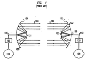
- FIG. 1 shows a diagram of two prior art telescope optical communication telescopes, 101 and 102, during normal aligned operating conditions in a free-space optical communications system.
- Laser 130 produces an optical light beam that is modulated with data received from network 110 and transmitted on optical fiber 106.
- the transmit telescope 101 receives the modulated optical signal via optical fiber 106.
- the primary mirror 120 and secondary mirror 121 optically shape and transmit the modulated light beam such that the beam is incident upon the focal plane 125 of receive telescope 102.
- Receive telescope 102 utilizes its optics, consisting of a primary mirror 122 and a secondary mirror 123, to focus the incident transmitted modulated light beam 103 onto the receive optical fiber 112 at the focal plane 125 of the receive telescope 102.
- the receive optical fiber then transmits the modulated optical signal to receiver 129 which converts the optical signal to an electrical signal, demodulates the data, and forwards the data to network 109.
- the light beam transmitted by transmitting telescope 101 may not be incident upon the optical fiber at the focal plane of the receive telescope 102.
- installation of the telescopes will require an initial alignment to insure that the transmitted beam is incident upon the focal plane of the receive telescope. This is necessary to establish initial communications connectivity between the transmit and receive telescopes.
- atmospheric interference such as turbulence 204 or attenuation 205, anywhere along the path between telescopes 201 and 202, may cause the transmitted beam 203 to deviate from the direct path between the transmit and receive telescopes such that it partially or entirely misses the receive telescope 202. The result is the loss or degradation of communications between the two telescopes. In this case, realignment may be necessary to possibly reestablish communications and to maximize received signal power.
- FIG. 3 shows another prior art situation where the light beam transmitted by the transmit telescope is not incident upon the receive telescope's focal plane.
- transmit telescope 301 transmits light beam 303, which is not incident upon the receive telescope 302 due to initial misalignment or relative movement between the transmit and receive telescopes during communications operations.
- Such movement during communications operations could result from high wind conditions, movement of the underlying support structure, or any number of other potential causes.
- FIG. 4 shows one embodiment of the present invention that utilizes variable divergence of the transmitted light beam to initially align the transmit and receive telescopes and/or to realign a misalignment of the transmit and receive telescopes during communications, as discussed above.
- laser 419 produces a light beam that can be modulated by modulator 418 with data from network 410.
- This modulated light beam is then transmitted to telescope 401 which shapes the beam 403 so that it is incident on the focal plane of receive telescope 402, which is connected to network 409.
- network 409 may be a physical, hard-wired, relatively low-bandwidth connection 417 between networks 409 and 410, the free-space system provides a high-speed and high-capacity link between these networks.
- the transmitted light beam may not be incident upon the focal plane of the receive telescope 402.
- the optical fiber 406 at the focal plane of the transmit telescope is moved in the z-direction to a point in front of the focal plane along the transmit telescope's longitudinal axis of its primary mirror 420 thereby causing light beam 504 to diverge as it is transmitted from the transmit telescope.
- the light beam diverges with an increasing cross-section area as the distance from the transmit telescope 401 increases. This, therefore, increases the likelihood that the diverging transmitted beam 403 will be incident upon the optical fiber, 412 in FIG.
- the transmitted beam can again be focused by reducing the divergence through the movement of the optical fiber 406 in the z-direction back toward the focal plane of the transmit telescope.
- the smaller cross section of the transmitted beam thus results in more power per unit area of the transmitted beam at the receive telescope.
- a feedback mechanism is desirable to communicate information there between.
- the incoming light beam is converted by photo-detector 432 to an electrical signal, which is passed to receiver 429.
- Power meter 408 measures the signal power of the received signal and passes this measurement to controller 430. During initial alignment stages this received signal power may be zero or below a specified minimum level. Controller 430 then sends a signal to controller 415 at the transmit telescope to initiate divergence of the transmitted light beam.
- controller 415 When controller 415 receives this signal, it outputs a signal to motorized stage 416 that effects the movement of optical fiber 406 to the front of the focal plane of the transmit telescope 401 along the longitudinal axis of it's primary mirror (z-axis).
- any mechanism for moving the optical fiber at the focal plane of the transmit telescope in the z-direction such as a calibrated indent using finite steps, may be used. Such devices are well known in the art.
- this movement of the optical fiber to a point in front of the focal plane of the transmit telescope results in the divergence of transmitted light beam 403 such that it presents an increased cross-section at the receive telescope 402.
- the entire transmit telescope is moved using gimbals, or any well-known equivalent device, to redirect the transmitted beam so that it is incident upon the receive telescope.
- mirrors defined by a non-standard conic constant may be used in the optics of the transmit and receive telescopes 401 and 402, respectively. The use of such mirrors in free-space optical communications is the subject of the aforementioned copending patent applications which are incorporated herein by reference.
- Mirrors with a non-standard conic constant are advantageous in that their use in free-space optical communications obviates, within limits, the need to move the entire transmit telescope structure to achieve initial alignment or to correct alignment during communications operations. Rather, by using such mirrors, the focal plane of the transmit and receive telescope is enlarged. By moving the transmit optical fiber within that enlarged focal plane, the resultant beam is transmitted in a different angular direction relative to the transmit telescope. Therefore, as opposed to moving the entire telescope apparatus 401 itself, as is necessary with prior art free-space communication telescopes, a transmit telescope utilizing mirrors with a non-standard conic constant may be aligned by moving optical fiber 406 in the x-y plane within the focal plane of the transmit telescope so that the transmitted beam is incident upon the receive telescope.
- any misalignment due to movement of the transmit telescope may be corrected by moving either the transmit telescope or the transmit optical fiber, as described above.
- the entire receive telescope 402 is moved using gimbals, or any well-known equivalent devices, to achieve alignment between the transmit and receive telescopes and, accordingly, maximize received signal power.
- moving the entire receive telescope may be unnecessary.
- a receive telescope utilizing mirrors with a non-standard conic constant may be aligned with the transmit telescope by moving optical fiber 412 in the x-y plane within the focal plane of the receive telescope so that the transmitted beam is incident upon the receive optical fiber.
- controller 430 at the receive telescope sends a signal to controller 415 at the transmit telescope that will cause it to reduce the divergence of the transmitted beam. This is achieved through motorized stage 416, which moves optical fiber 406 to a point along the longitudinal axis of the primary mirror 420 (z-axis) of the transmit telescope that is closer to its focal plane. Iterative power measurements, followed by variations of the degree of divergence of the transmitted beam 403 and movements of the receive telescope 402 or the receive optical fiber 412 in response to those measurements, may be necessary to achieve alignment of the transmit and receive telescopes 401 and 402, respectively.
- the resulting maximum power level is not the optimum level for communications operations.
- the maximum transmitted power level must be such that communications are possible even in foggy or snowy atmospheric conditions. This means that in clear atmospheric conditions, for example, the maximum received power level may overload the receiver electronics. Therefore, if the received power exceeds a specified threshold, the power received by the receive optical fiber can be reduced by moving the optical fiber of either the transmit or receive telescope 401 and 402, respectively, along the z-axis of the primary mirror of the respective telescope.
- this reduction in received power is accomplished by moving the transmit optical fiber 406 to a point in front of the focal plane of the transmit telescope along the z-axis of its primary mirror 420.
- controller 430 sends a signal to controller 415 at the transmit telescope to reduce the transmitted power.
- Controller 415 then sends a signal to motorized stage 416 to effect the movement of optical fiber 406 to a point in front of the focal plane along the axis of the transmit telescope's primary mirror (z-axis).
- such a movement of the transmit optical fiber 406 causes the transmitted light beam 504 to diverge and, correspondingly, increases the cross-sectional area of the transmitted beam at the focal plane of the receive telescope. Also as previously described, this increase in the beam's cross-sectional area reduces the power per unit area of the cross section of the received signal, resulting in less power being incident upon the receive optical fiber, 412 in FIG. 4, at the focal plane of the receive telescope 402. Iterative measurements of received signal power by power meter 408 followed by feedback to the transmit controller 415 allow adjustment of the position of transmit optical fiber 406 to maintain the received power levels below the specified maximum power threshold. A similar reduction in received power may be achieved by moving the transmit optical fiber to the rear of the focal plane of the transmit telescope.
- a reduction in received power is accomplished by moving the receive optical fiber in the z-direction along the axis of the receive telescope's primary mirror 422.
- the fiber optic may be moved either to a point in front of the focal plane of the receive telescope or, alternatively, to a point to the rear of the focal plane of the receive telescope. Either movement will result in a reduced signal power incident upon the receive optical fiber with no degradation in the received signal quality.
- FIG. 6 shows the case where the receive optical fiber is moved to a point to the rear of the receive focal plane.
- receive telescope 402 utilizes its primary and secondary mirrors 422 and 423, respectively, to focus the incoming light beam on point 601 within the focal plane of primary mirror 422.
- This focal point is the point of maximum received power.
- controller 430 sends a signal to XYZ positioner 411 to effect the movement of optical fiber 412 to a point which is some distance from the rear of focal point 601, such as distance 603, thereby reducing the power incident upon the receive optical fiber.
- controller 430 may send signals to XYZ positioner 411 to adjust the location of receive optical fiber 412 to maintain optimum received power levels that do not exceed a specified power threshold.
Landscapes
- Physics & Mathematics (AREA)
- Electromagnetism (AREA)
- Engineering & Computer Science (AREA)
- Computer Networks & Wireless Communication (AREA)
- Signal Processing (AREA)
- Optical Communication System (AREA)
Claims (37)
- Sendeteleskop (401) mit einem Mittel zum Senden eines Lichtstrahls (403) zu einem abgesetzten Empfangsteleskop (402), wobei das Sendeteleskop durch folgendes gekennzeichnet ist:ein Mittel, das als Reaktion auf ein durch das abgesetzte Empfangsteleskop (402) erzeugtes Signal wirkt, wobei das Signal einen Fehlausrichtungszustand zwischen dem abgesetzten Empfangsteleskop (402) und dem Sendeteleskop (401) anzeigt, um die Querschnittsfläche des gesendeten Strahls (403) zu vergrößern.
- Sendeteleskop (401) nach Anspruch 1, wobei das Mittel zum Vergrößern der Querschnittsfläche des gesendeten Strahls (403) ein Mittel zum Einstellen des gesendeten Lichtstrahls (403) dergestalt, daß er solange divergiert, wenn der Lichtstrahl (403) durch das Sendemittel gesendet wird, bis mindestens ein Teil des Lichtstrahls (403) auf einen abgesetzten Empfangslichtwellenleiter (412) an oder in der Nähe der Fokalebene eines optischen Systems des abgesetzten Empfangsteleskops (402) einfällt, umfaßt.
- Sendeteleskop (401) nach Anspruch 2, wobei das Mittel zum Einstellen des Lichtstrahls (403) ein Mittel zum Bewegen eines Lichtwellenleiters (406) des Sendeteleskops, der den Lichtstrahl (403) zu dem Sendeteleskop (401) übermittelt und an oder in der Nähe der Fokalebene eines optischen Systems des Sendeteleskops (401) endet, zu einem Punkt vor der Fokalebene entlang der Längsachse des optischen Systems des Sendeteleskops (401) umfaßt.
- Sendeteleskop (401) nach Anspruch 1, wobei das einen Fehlausrichtungszustand anzeigende Signal als Reaktion auf mindestens einen meßbaren Signalparameter erzeugt wird, der dem durch das Empfangsteleskop (402) empfangenen gesendeten Lichtstrahl (403) zugeordnet ist.
- Sendeteleskop (401) nach Anspruch 4, wobei der meßbare Signalparameter Signalleistung ist.
- Sendeteleskop (401) nach Anspruch 1, weiterhin mit einem Mittel zum Bewegen des Sendeteleskops (401), bis in einem Lichtwellenleiter (412) des abgesetzten Empfangsteleskops eine maximale Leistung erkannt wird.
- Sendeteleskop (401) nach Anspruch 3, weiterhin mit einem Mittel zum Bewegen des Lichtwellenleiters des Sendeteleskops (401), bis in dem Lichtwellenleiter (412) des abgesetzten Empfangsteleskops eine maximale Leistung erkannt wird.
- Abgesetztes Empfangsteleskop (402) mit einem Mittel zum Empfangen eines von einem Sendeteleskop (401) gesendeten Lichtstrahls (403), wobei das abgesetzte Empfangsteleskop durch folgendes gekennzeichnet ist:ein Mittel zum Erzeugen eines Signals, das einen Fehlausrichtungszustand zwischen dem abgesetzten Empfangsteleskop (402) und dem Sendeteleskop (401) anzeigt, in dem abgesetzten Empfangsteleskop (402), das wirkt, um die Querschnittsfläche des gesendeten Strahls (403) zu vergrößern.
- Abgesetztes Empfangsteleskop (402) nach Anspruch 8, wobei das Erzeugungsmittel wirkt, um die Querschnittsfläche des Lichtstrahls (403) solange einzustellen, bis mindestens ein Teil des Lichtstrahls (403) auf einen Lichtwellenleiter (412) des abgesetzten Empfangsteleskops an oder in der Nähe der Fokalebene eines optischen Systems des abgesetzten Empfangsteleskops (402) einfällt.
- Abgesetztes Empfangsteleskop (402) nach Anspruch 8, wobei das einen Fehlausrichtungszustand anzeigende Signal als Reaktion auf mindestens einen meßbaren Signalparameter erzeugt wird, der dem empfangenen Lichtstrahl (403) zugeordnet ist.
- Abgesetztes Empfangsteleskop (402) nach Anspruch 10, wobei der meßbare Signalparameter Signalleistung ist.
- Abgesetztes Empfangsteleskop (402) nach Anspruch 11, weiterhin mit einem Mittel zum Bewegen des abgesetzten Empfangsteleskops (402), bis in einem Lichtwellenleiter (412) des abgesetzten Empfangsteleskops eine maximale Signalleistung erkannt wird.
- Abgesetztes Empfangsteleskop (402) nach Anspruch 11, weiterhin mit einem Mittel zum Bewegen des Lichtwellenleiters (412) des abgesetzten Empfangsteleskops in der Fokalebene des optischen Systems des abgesetzten Empfangsteleskops (402), bis eine maximale Leistung erkannt wird.
- Verfahren in einem optischen Freiraum-Kommunikationssystem, mit den folgenden Schritten:Vergrößern, als Reaktion auf ein durch ein abgesetztes Empfangsteleskop (402) erzeugtes Signal, wobei das Signal einen Fehlausrichtungszustand zwischen dem abgesetzten Empfangsteleskop (402) und einem Sendeteleskop (401) anzeigt, der Querschnittsfläche eines durch das Sendeteleskop (401) gesendeten Lichtstrahls (403).
- Verfahren nach Anspruch 14, wobei das Vergrößern der Querschnittsfläche des gesendeten Lichtstrahls (403) ein Einstellen des Strahls (403) dergestalt, daß er solange divergiert, wenn er durch das Sendeteleskop (401) gesendet wird, bis mindestens ein Teil des gesendeten Lichtstrahls (403) auf einen Lichtwellenleiter (412) des abgesetzten Empfangsteleskops an oder in der Nähe der Fokalebene eines optischen Systems des abgesetzten Empfangsteleskops (402) einfällt, umfaßt.
- Verfahren nach Anspruch 15, wobei das Einstellen des Strahls (403) dergestalt, daß er divergiert, ein Bewegen eines Lichtwellenleiters des Sendeteleskops (401), der den Lichtstrahl (403) zu dem Sendeteleskop (401) übermittelt und an oder in der Nähe der Fokalebene eines optischen Systems des Sendeteleskops (401) endet, zu einem Punkt vor der Fokalebene entlang der Längsachse des optischen Systems des Sendeteleskops (401) umfaßt.
- Verfahren nach Anspruch 16, wobei das einen Fehlausrichtungszustand anzeigende Signal als Reaktion auf mindestens einen meßbaren Signalparameter erzeugt wird, der dem empfangenen Lichtstrahl (403) zugeordnet ist.
- Verfahren nach Anspruch 17, wobei der meßbare Signalparameter Signalleistung ist.
- Verfahren nach Anspruch 18, weiterhin mit dem Schritt des Bewegens des Sendeteleskops (401), bis in dem Lichtwellenleiter (412) des abgesetzten Empfangsteleskops eine maximale Signalleistung erkannt wird.
- Verfahren nach Anspruch 19, weiterhin mit dem Schritt des Reduzierens der Divergenz des gesendeten Lichtstrahls (403), nachdem eine maximale Leistung in dem Lichtwellenleiter (412) des abgesetzten Empfangsteleskops erkannt wurde.
- Verfahren nach Anspruch 20, bei dem weiterhin nach dem Reduzieren der Divergenz das Sendeteleskop (401) bewegt wird, bis in dem Lichtwellenleiter (412) des abgesetzten Empfangsteleskops eine maximale Leistung erkannt wird.
- Verfahren nach Anspruch 18, bei dem weiterhin der Lichtwellenleiter des Sendeteleskops (401) bewegt wird, bis in dem Lichtwellenleiter (412) des abgesetzten Empfangsteleskops eine maximale Leistung erkannt wird.
- Verfahren nach Anspruch 22, bei dem weiterhin die Divergenz des gesendeten Lichtstrahls (403) reduziert wird, nachdem in dem Lichtwellenleiter (412) des abgesetzten Empfangsteleskops eine maximale Leistung erkannt wurde.
- Verfahren nach Anspruch 23, bei dem weiterhin nach dem Reduzieren der Divergenz der Lichtwellenleiter des Sendeteleskops (401) bewegt wird, bis in dem Lichtwellenleiter (412) des abgesetzten Empfangsteleskops eine maximale Leistung erkannt wird.
- Verfahren nach Anspruch 18, bei dem weiterhin das abgesetzte Empfangsteleskop (402) bewegt wird, bis in dem Lichtwellenleiter (412) des abgesetzten Empfangsteleskops eine maximale Signalleistung erkannt wird.
- Verfahren nach Anspruch 25, bei dem weiterhin die Divergenz des gesendeten Lichtstrahls (403) reduziert wird, nachdem in dem Lichtwellenleiter (412) des abgesetzten Empfangsteleskops eine maximale Leistung erkannt wurde.
- Verfahren nach Anspruch 26, bei dem weiterhin nach dem Reduzieren der Divergenz das abgesetzte Empfangsteleskop (402) bewegt wird, bis in dem Lichtwellenleiter (412) des Empfangsteleskops eine maximale Leistung erkannt wird.
- Verfahren nach Anspruch 18, bei dem weiterhin der Lichtwellenleiter (412) des abgesetzten Empfangsteleskops in der Fokalebene des optischen Systems des abgesetzten Empfangsteleskops (402) bewegt wird, bis in dem Lichtwellenleiter (412) des Empfangsteleskops eine maximale Leistung erkannt wird.
- Verfahren nach Anspruch 28, bei dem weiterhin die Divergenz des gesendeten Lichtstrahls (403) reduziert wird, nachdem in dem Lichtwellenleiter (412) des abgesetzten Empfangsteleskops eine maximale Leistung erkannt wurde.
- Verfahren nach Anspruch 29, bei dem weiterhin nach dem Reduzieren der Divergenz der Lichtwellenleiter (412) des abgesetzten Empfangsteleskops in der Fokalebene des optischen Systems des abgesetzten Empfangsteleskops (402) bewegt wird, bis in dem Lichtwellenleiter (412) des abgesetzten Empfangsteleskops eine maximale Leistung erkannt wird.
- Optisches Freiraum-Kommunikationssystem mit einem Sendeteleskop (401), das so angeordnet ist, daß es einen Lichtstrahl (403) sendet, und einem abgesetzten Empfangsteleskop (402), das so angeordnet ist, daß es den gesendeten Lichtstrahl (403) empfängt, wobei das Kommunikationssystem durch folgendes gekennzeichnet ist:ein Mittel, das als Reaktion auf ein Erkennen, in dem abgesetzten Empfangsteleskop (402), eines Fehlausrichtungszustands zwischen dem abgesetzten Empfangsteleskop (402) und dem Sendeteleskop (401) und ein durch das abgesetzte Empfangsteleskop (402) erzeugtes resultierendes Signal, das einen Fehlausrichtungszustand zwischen dem Sendeteleskop und dem abgesetzten Empfangsteleskop (402) anzeigt, wirkt, um die Querschnittsfläche des gesendeten Lichtstrahls (403) zu vergrößern.
- System nach Anspruch 31, wobei das Mittel zum Vergrößern ein Mittel zum Einstellen des gesendeten Lichtstrahls (403) dergestalt, daß er solange divergiert, wenn der Lichtstrahl (403) durch das Sendemittel gesendet wird, bis mindestens ein Teil des Lichtstrahls (403) auf einen abgesetzten Empfangslichtwellenleiter (412) an oder in der Nähe der Fokalebene eines optischen Systems des abgesetzten Empfangsteleskops (402) einfällt, umfaßt.
- System nach Anspruch 32, wobei das Mittel zum Einstellen des Lichtstrahls (403) dergestalt, daß er divergiert, ein Mittel zum Bewegen eines Lichtwellenleiters des Sendeteleskops (401), der den Lichtstrahl (403) zu dem Sendeteleskop (401) übermittelt und an oder in der Nähe der Fokalebene des optischen Systems des Sendeteleskops (401) endet, zu einem Punkt vor der Fokalebene entlang der Längsachse des optischen Systems des Sendeteleskops (401) umfaßt.
- System nach Anspruch 31, wobei das einen Fehlausrichtungszustand anzeigende Signal als Reaktion auf mindestens einen meßbaren Signalparameter erzeugt wird, der dem durch das abgesetzte Empfangsteleskop (402) empfangenen gesendeten Lichtstrahl (403) zugeordnet ist.
- System nach Anspruch 34, wobei der meßbare Signalparameter Signalleistung ist.
- System nach Anspruch 35, wobei das Sendeteleskop (401) weiterhin ein Mittel zum Bewegen des Sendeteleskops (401), bis in einem Lichtwellenleiter (412) des abgesetzten Empfangsteleskops eine maximale Signalleistung erkannt wird, umfaßt.
- System nach Anspruch 35, wobei das Sendeteleskop (401) weiterhin ein Mittel zum Bewegen des Lichtwellenleiters (406) des Sendeteleskops, bis in dem Lichtwellenleiter (412) des abgesetzten Empfangsteleskops eine maximale Leistung erkannt wird, umfaßt.
Applications Claiming Priority (2)
| Application Number | Priority Date | Filing Date | Title |
|---|---|---|---|
| US680336 | 2000-05-10 | ||
| US09/680,336 US6657783B1 (en) | 2000-10-05 | 2000-10-05 | Method and apparatus for aligning telescopes within a free-space optical communication system |
Publications (2)
| Publication Number | Publication Date |
|---|---|
| EP1158704A1 EP1158704A1 (de) | 2001-11-28 |
| EP1158704B1 true EP1158704B1 (de) | 2003-04-16 |
Family
ID=24730678
Family Applications (1)
| Application Number | Title | Priority Date | Filing Date |
|---|---|---|---|
| EP01303943A Expired - Lifetime EP1158704B1 (de) | 2000-05-10 | 2001-04-30 | Verfahren und Vorrichtung zum Ausrichten von Teleskopen in optischen Verbindungen in freien Raum |
Country Status (6)
| Country | Link |
|---|---|
| US (1) | US6657783B1 (de) |
| EP (1) | EP1158704B1 (de) |
| JP (1) | JP2002164852A (de) |
| CN (1) | CN1348265A (de) |
| CA (1) | CA2357660C (de) |
| DE (1) | DE60100183T2 (de) |
Families Citing this family (22)
| Publication number | Priority date | Publication date | Assignee | Title |
|---|---|---|---|---|
| US20030001073A1 (en) * | 2001-06-29 | 2003-01-02 | Presby Herman Melvin | Method and apparatus for the correction of optical signal wave front distortion within a free-space optical communication system |
| US20030034432A1 (en) * | 2001-06-29 | 2003-02-20 | Presby Herman Melvin | Method and apparatus for the correction of optical signal wave front distortion within a free-space optical communication system |
| US7106973B2 (en) * | 2002-08-13 | 2006-09-12 | Lightpointe Communications, Inc. | Apparatus and method for use in free-space optical communication comprising optically aligned components integrated on circuit boards |
| US7120363B2 (en) * | 2002-12-20 | 2006-10-10 | Lightpointe Communications, Inc. | Method and apparatus for maintaining optical alignment for free-space optical communication |
| US20040141753A1 (en) * | 2003-01-21 | 2004-07-22 | Lightpointe Communications, Inc. | Apparatus and method for tracking in free-space optical communication systems |
| US7171126B2 (en) * | 2003-09-30 | 2007-01-30 | Northrop Grumman Corporation | Airborne free-space-optical system utilizing three-tier, ultrafine steering |
| US7308203B1 (en) | 2004-07-15 | 2007-12-11 | Rockwell Collins, Inc. | Free space optical data link for aircraft |
| CN100428654C (zh) * | 2005-03-29 | 2008-10-22 | 北京理工大学 | 一种自由空间光通信系统 |
| US7606496B1 (en) * | 2005-06-02 | 2009-10-20 | Rockwell Collins, Inc. | Communications and position location system and method |
| US7657182B2 (en) * | 2005-08-04 | 2010-02-02 | Panasonic Corporation | Liquid lens optical transmitter system |
| US8301032B2 (en) * | 2008-02-12 | 2012-10-30 | Arun Kumar Majumdar | Wide field-of-view amplified fiber-retro for secure high data rate communications and remote data transfer |
| DE102008020466A1 (de) * | 2008-04-23 | 2009-10-29 | Deutsche Telekom Ag | Drahtlose Datenübertragung mit Terahertz-Wellen |
| US7994460B2 (en) | 2008-06-30 | 2011-08-09 | Lawrence Livermore National Security, Llc | Method and system for controlling the position of a beam of light |
| US8200093B2 (en) * | 2008-09-26 | 2012-06-12 | The Boeing Company | Multi-channel optical relays for enabling a networked communications system |
| EP3092732A1 (de) * | 2014-01-10 | 2016-11-16 | Palmer Labs, LLC | Kommunikationssystem mit abgelenktem strahl |
| US9571192B2 (en) * | 2014-05-21 | 2017-02-14 | Space Photonics, Inc. | Simultaneous multi-channel optical communications system with beam pointing, switching, and tracking using moving focal plane devices |
| CN104570385B (zh) * | 2014-12-30 | 2017-07-14 | 中国科学院长春光学精密机械与物理研究所 | 具有二级稳像功能的机上自适应光学系统 |
| US10039103B2 (en) | 2016-05-17 | 2018-07-31 | X Development Llc | Acquisition and tracking apparatus for free space optical communications |
| US10601506B2 (en) | 2016-06-13 | 2020-03-24 | Bae Systems, Plc | Optical communication device |
| US10371508B1 (en) | 2018-04-04 | 2019-08-06 | X Development Llc | Method for alignment of phase-sensitive tracking systems using variable delay offsets |
| US11711145B2 (en) * | 2019-03-25 | 2023-07-25 | Signify Holding B.V. | Beam locking for free space optical communication using vertical-cavity surface-emitting lasers |
| CN113285224B (zh) * | 2021-03-01 | 2022-09-27 | 中国科学院新疆天文台 | 一种射电望远镜远场区域强电磁干扰规避方法 |
Family Cites Families (9)
| Publication number | Priority date | Publication date | Assignee | Title |
|---|---|---|---|---|
| GB1292298A (en) * | 1969-01-24 | 1972-10-11 | Aga Ab | Light signal apparatus |
| US4090067A (en) | 1976-11-02 | 1978-05-16 | Sperry Rand Corporation | Optical data communication system |
| FR2622754B1 (fr) | 1987-10-29 | 1990-01-12 | Alcatel Espace | Systeme de transmission radiofrequence-optique, notamment dans le domaine des telecommunications spatiales |
| US4960315A (en) | 1989-05-19 | 1990-10-02 | At&T Bell Laboratories | Atmosphric optical communication link |
| US4995101A (en) * | 1989-09-19 | 1991-02-19 | Gte Government Systems Corporation | Secure two-way communications with submerged submarines |
| US5142400A (en) | 1989-12-26 | 1992-08-25 | Cubic Corporation | Method and apparatus for automatic acquisition and alignment of an optical beam communication link |
| US5475520A (en) | 1994-06-22 | 1995-12-12 | Hughes Aircraft Company | Satellite communications system |
| US6239888B1 (en) | 1998-04-24 | 2001-05-29 | Lightpointe Communications, Inc. | Terrestrial optical communication network of integrated fiber and free-space links which requires no electro-optical conversion between links |
| JP2000147324A (ja) * | 1998-11-06 | 2000-05-26 | Sony Corp | 光ファイバ接続器とこれを用いた光送受信装置 |
-
2000
- 2000-10-05 US US09/680,336 patent/US6657783B1/en not_active Expired - Fee Related
-
2001
- 2001-04-30 EP EP01303943A patent/EP1158704B1/de not_active Expired - Lifetime
- 2001-04-30 DE DE60100183T patent/DE60100183T2/de not_active Expired - Fee Related
- 2001-09-24 CA CA002357660A patent/CA2357660C/en not_active Expired - Fee Related
- 2001-09-28 CN CN01141211A patent/CN1348265A/zh active Pending
- 2001-10-03 JP JP2001307406A patent/JP2002164852A/ja active Pending
Also Published As
| Publication number | Publication date |
|---|---|
| DE60100183T2 (de) | 2004-03-11 |
| US6657783B1 (en) | 2003-12-02 |
| CN1348265A (zh) | 2002-05-08 |
| EP1158704A1 (de) | 2001-11-28 |
| DE60100183D1 (de) | 2003-05-22 |
| CA2357660C (en) | 2006-01-24 |
| CA2357660A1 (en) | 2002-04-05 |
| JP2002164852A (ja) | 2002-06-07 |
Similar Documents
| Publication | Publication Date | Title |
|---|---|---|
| EP1158704B1 (de) | Verfahren und Vorrichtung zum Ausrichten von Teleskopen in optischen Verbindungen in freien Raum | |
| US6934477B2 (en) | Method and apparatus for free-space optical communication without eletro-optical conversion | |
| US6868237B2 (en) | Terrestrial optical communication network of integrated fiber and free-space links which requires no electro-optical conversion between links | |
| US20030067657A1 (en) | Method and apparatus to compensate for atmospheric effects and target motion in laser communication system | |
| US7286766B2 (en) | Free space optical communication system with power level management | |
| US20030090765A1 (en) | Free-space optical communication system | |
| US6829439B1 (en) | Optical communication device | |
| US6643467B1 (en) | Method and apparatus for controlling received power levels within a free space optical communication system | |
| US6944403B2 (en) | MEMS based over-the-air optical data transmission system | |
| EP1130808B1 (de) | Verfahren und Vorrichtung zur automatischen Spurnachführung eines optischen Signals in einem drahtlosen optischen Übertragungssystem | |
| CN101577583B (zh) | 大气激光通信自动跟踪方法和系统 | |
| CA2013246C (en) | Atmospheric optical communication link | |
| US20030001073A1 (en) | Method and apparatus for the correction of optical signal wave front distortion within a free-space optical communication system | |
| US20020081060A1 (en) | MEMS based over-the-air optical data transmission system | |
| EP1411653A2 (de) | Verfahren und Vorrichtung zum Steuern der Sendeleistung in einem optischen Freiraumübertragungssystem | |
| US20040208597A1 (en) | Free-Space optical transceiver link | |
| EP1154591B1 (de) | Verfahren und Vorrichtung zur Übertragungssignalnachführung in einem optischen Freiraumübertragungssystem | |
| EP1130807B1 (de) | Übertragungsgerät für optisches Freiraumsignal | |
| US20030034432A1 (en) | Method and apparatus for the correction of optical signal wave front distortion within a free-space optical communication system | |
| EP1162770A2 (de) | Optische Übertragungsanordnung im freien Raum | |
| Zhou et al. | Control algorithm development for mobile FSO node alignment | |
| CN111510222A (zh) | 无人机与地面激光通信的大气湍流预补偿装置 | |
| Perlot et al. | Single-mode optical antenna for high-speed and quantum communications |
Legal Events
| Date | Code | Title | Description |
|---|---|---|---|
| PUAI | Public reference made under article 153(3) epc to a published international application that has entered the european phase |
Free format text: ORIGINAL CODE: 0009012 |
|
| 17P | Request for examination filed |
Effective date: 20010511 |
|
| AK | Designated contracting states |
Kind code of ref document: A1 Designated state(s): AT BE CH CY DE DK ES FI FR GB GR IE IT LI LU MC NL PT SE TR Kind code of ref document: A1 Designated state(s): DE ES FI FR GB IT |
|
| AX | Request for extension of the european patent |
Free format text: AL;LT;LV;MK;RO;SI |
|
| 17Q | First examination report despatched |
Effective date: 20020125 |
|
| AKX | Designation fees paid |
Free format text: DE ES FI FR GB IT |
|
| GRAH | Despatch of communication of intention to grant a patent |
Free format text: ORIGINAL CODE: EPIDOS IGRA |
|
| GRAH | Despatch of communication of intention to grant a patent |
Free format text: ORIGINAL CODE: EPIDOS IGRA |
|
| GRAA | (expected) grant |
Free format text: ORIGINAL CODE: 0009210 |
|
| AK | Designated contracting states |
Designated state(s): DE ES FI FR GB IT |
|
| PG25 | Lapsed in a contracting state [announced via postgrant information from national office to epo] |
Ref country code: FI Free format text: LAPSE BECAUSE OF FAILURE TO SUBMIT A TRANSLATION OF THE DESCRIPTION OR TO PAY THE FEE WITHIN THE PRESCRIBED TIME-LIMIT Effective date: 20030416 |
|
| REG | Reference to a national code |
Ref country code: GB Ref legal event code: FG4D |
|
| RIN1 | Information on inventor provided before grant (corrected) |
Inventor name: TYSON, JOHN A. Inventor name: PRESBY, HERMAN MELVIN |
|
| REF | Corresponds to: |
Ref document number: 60100183 Country of ref document: DE Date of ref document: 20030522 Kind code of ref document: P |
|
| PG25 | Lapsed in a contracting state [announced via postgrant information from national office to epo] |
Ref country code: ES Free format text: LAPSE BECAUSE OF FAILURE TO SUBMIT A TRANSLATION OF THE DESCRIPTION OR TO PAY THE FEE WITHIN THE PRESCRIBED TIME-LIMIT Effective date: 20031030 |
|
| ET | Fr: translation filed | ||
| PLBE | No opposition filed within time limit |
Free format text: ORIGINAL CODE: 0009261 |
|
| STAA | Information on the status of an ep patent application or granted ep patent |
Free format text: STATUS: NO OPPOSITION FILED WITHIN TIME LIMIT |
|
| 26N | No opposition filed |
Effective date: 20040119 |
|
| PGFP | Annual fee paid to national office [announced via postgrant information from national office to epo] |
Ref country code: IT Payment date: 20060430 Year of fee payment: 6 |
|
| PGFP | Annual fee paid to national office [announced via postgrant information from national office to epo] |
Ref country code: DE Payment date: 20070426 Year of fee payment: 7 |
|
| PGFP | Annual fee paid to national office [announced via postgrant information from national office to epo] |
Ref country code: GB Payment date: 20070425 Year of fee payment: 7 |
|
| PGFP | Annual fee paid to national office [announced via postgrant information from national office to epo] |
Ref country code: FR Payment date: 20070411 Year of fee payment: 7 |
|
| GBPC | Gb: european patent ceased through non-payment of renewal fee |
Effective date: 20080430 |
|
| PG25 | Lapsed in a contracting state [announced via postgrant information from national office to epo] |
Ref country code: DE Free format text: LAPSE BECAUSE OF NON-PAYMENT OF DUE FEES Effective date: 20081101 |
|
| REG | Reference to a national code |
Ref country code: FR Ref legal event code: ST Effective date: 20081231 |
|
| PG25 | Lapsed in a contracting state [announced via postgrant information from national office to epo] |
Ref country code: FR Free format text: LAPSE BECAUSE OF NON-PAYMENT OF DUE FEES Effective date: 20080430 |
|
| PG25 | Lapsed in a contracting state [announced via postgrant information from national office to epo] |
Ref country code: GB Free format text: LAPSE BECAUSE OF NON-PAYMENT OF DUE FEES Effective date: 20080430 |
|
| PG25 | Lapsed in a contracting state [announced via postgrant information from national office to epo] |
Ref country code: IT Free format text: LAPSE BECAUSE OF NON-PAYMENT OF DUE FEES Effective date: 20070430 |