EP1158284A2 - Methods and apparatus for high cycle fatigue life test - Google Patents
Methods and apparatus for high cycle fatigue life test Download PDFInfo
- Publication number
- EP1158284A2 EP1158284A2 EP01304439A EP01304439A EP1158284A2 EP 1158284 A2 EP1158284 A2 EP 1158284A2 EP 01304439 A EP01304439 A EP 01304439A EP 01304439 A EP01304439 A EP 01304439A EP 1158284 A2 EP1158284 A2 EP 1158284A2
- Authority
- EP
- European Patent Office
- Prior art keywords
- capacitance
- component
- frequency
- oscillator
- probe
- Prior art date
- Legal status (The legal status is an assumption and is not a legal conclusion. Google has not performed a legal analysis and makes no representation as to the accuracy of the status listed.)
- Withdrawn
Links
- 238000012360 testing method Methods 0.000 title claims abstract description 42
- 238000000034 method Methods 0.000 title claims description 19
- 239000000523 sample Substances 0.000 claims abstract description 61
- 230000000694 effects Effects 0.000 claims abstract description 12
- 238000006073 displacement reaction Methods 0.000 claims description 19
- 239000003990 capacitor Substances 0.000 claims description 16
- 239000013078 crystal Substances 0.000 claims description 8
- 238000009661 fatigue test Methods 0.000 description 3
- 230000007423 decrease Effects 0.000 description 2
- 238000010586 diagram Methods 0.000 description 2
- 238000009674 high cycle fatigue testing Methods 0.000 description 2
- 230000035945 sensitivity Effects 0.000 description 2
- 230000002411 adverse Effects 0.000 description 1
- 230000005674 electromagnetic induction Effects 0.000 description 1
- 238000010438 heat treatment Methods 0.000 description 1
- 238000004519 manufacturing process Methods 0.000 description 1
- 238000005259 measurement Methods 0.000 description 1
- 239000004065 semiconductor Substances 0.000 description 1
- 238000000926 separation method Methods 0.000 description 1
- 239000013077 target material Substances 0.000 description 1
Images

Classifications
-
- G—PHYSICS
- G01—MEASURING; TESTING
- G01H—MEASUREMENT OF MECHANICAL VIBRATIONS OR ULTRASONIC, SONIC OR INFRASONIC WAVES
- G01H11/00—Measuring mechanical vibrations or ultrasonic, sonic or infrasonic waves by detecting changes in electric or magnetic properties
- G01H11/06—Measuring mechanical vibrations or ultrasonic, sonic or infrasonic waves by detecting changes in electric or magnetic properties by electric means
Definitions
- This invention relates generally to life testing and, more particularly, to apparatus and methods for measuring frequency and displacement for a high cycle fatigue closed loop control.
- Life testing is typically utilized in connection with components used in applications that are subjected to wide temperature ranges and vibration amplitudes.
- a high cycle fatigue (HCF) portion of the life test uses a closed loop control to measure frequency and displacement of the components.
- the component being tested is installed on a test stand and shaken with an oscillator in an open loop mode.
- a capacitance probe is positioned next to the stand and measures a frequency and vibration amplitude of the component as it is shaken. Specifically, the capacitance probe measures the separation between the probe and a target material by determining an existing capacitance through a relationship between a charge and a potential difference between the two surfaces.
- the capacitance probe During the testing, as the component fatigues, a natural resonant frequency and amplitude of the component changes and the capacitance probe generates a signal representative of such changes.
- the signal generated by the capacitance probe is provided to the shaker closed loop control, and the shaker closed loop control operates to maintain the component vibration amplitude to a pre-set amplitude as the component fatigues.
- Known capacitance probes include an internal oscillator and a receiver circuit. Because different components are tested, often the internal oscillator is a free-running multi-vibrator circuit capable of transmitting various frequencies. However, because the oscillator is a free-running circuit, the frequency transmitted by the oscillator may drift during testing depending on a proximity of the capacitance probe to the component being tested. In addition, due to the sensitivity of the receiver circuit, undesirable noise and other signals transmitted by the oscillator or generated during testing are received by the receiver circuit and may adversely impact the testing.
- a testing method permits frequency and displacement for a high cycle fatigue life test of a component to be accurately measured. More specifically, and in one embodiment, a capacitance probe accurately detects, measures and tracks the frequency and amplitude changes of the component during the testing in a closed loop control.
- the probe includes an internal oscillator, a receiver circuit, a product detector, and a pair of gain amplifiers.
- the oscillator generates a single controlled frequency output received by the adjustable receiver circuit.
- the receiver circuit includes a capacitance bridge and is also adjustable to create a DC voltage shift that effectively nulls the capacitance bridge.
- the product detector detects an amplitude modulated product of the oscillator and the receiver circuit, and rejects undesirable frequencies before relaying a signal from the product detector.
- the gain amplifiers detect a DC voltage shift and permit the capacitance effect to be easily nulled.
- the gain amplifiers are also adjustable to prevent over-driving or over-amplifying of the output of the capacitance probe.
- the capacitance probe is placed adjacent the component and is used to detect and track the frequency and amplitude changes of the component.
- the capacitance probe transmits the changes in amplitude to the shaker closed loop control. Electric noise generated during the testing is eliminated with the use of the product detector and the gain amplifiers are adjusted to null the capacitance effect and permit a dynamic range of the output signal to be increased and centered such that the capacitance probe closed loop is stable.
- the capacitance probe provides accurate measurements of the frequency and displacement of a component during high cycle fatigue testing in a more accurate and cost-effective manner in comparison to known capacitance probes.
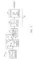
- FIG. 1 is block diagram of a capacitance probe 10 used to measure frequency and displacement for a high cycle fatigue life test of a component (not shown).
- capacitance probe 10 measures frequency and displacement for a high cycle fatigue life test of a gas turbine engine blade (not shown).
- Capacitance probe 10 operates in a closed loop control and includes a printed circuit board (not shown) including an oscillator 14, a receiver circuit 16, a product detector 18, and a plurality of gain amplifiers 20.
- the printed circuit board includes a ground plain (not shown) to minimize inducted noise into the circuit board.
- Oscillator 14 includes a crystal (not shown) that generates a single controlled frequency output that is constant. Accordingly, because oscillator 14 is not a free-running multivibrator circuit, the frequency output from oscillator 14 does not drift as capacitance probe 10 is moved physically closer or farther from the component being fatigue tested.
- oscillator 14 is a 5 MHz HS-100P oscillator available from Vishay Intertechnology, Inc., Malvern, Pennsylvania.
- Receiver circuit 16 includes a tuned capacitance bridge or a wheatstone bridge 24 including at least one adjustable capacitor 26.
- Capacitance probe 10 functions as a fourth capacitor for wheatstone bridge 26.
- Adjustable capacitor 26 also permits a capacitance effect to be adjusted and balanced to cause a DC voltage shift that effectively nulls capacitance bridge 24.
- tuned capacitance bridge 24 also includes two 30 pf capacitors 28 and adjustable capacitor 26 is a 5-25 pf adjustable capacitor available from Johanson Manufacturing Corporation, Boonton, New Jersey.
- Product detector 18 receives an output from receiver circuit 16 and detects an amplitude modulated product of oscillator 14. Product detector 18 also rejects undesirable frequencies before relaying a signal from product detector 18. In one embodiment, product detector 18 is an MC1496 balanced modulator/demodulator available from Motorola, Inc., Austin, Texas.
- a first gain amplifier 40 is a 50:1 gain amplifier and receives an output from product detector 18.
- First gain amplifier 40 includes two light emitting devices, LEDs, (not shown) used to visually indicate a detected DC voltage shift from the output of first gain amplifier 40. When the LEDs are energized and lit, an operator may adjust capacitance bridge 24 to null the capacitance and when effectively adjusted, both LEDs are de-energize and are not illuminated. After the capacitance effect is nulled, the output of the capacitance probe may be placed next to the test component without any DC voltage shifts occurring.
- a second gain amplifier 42 is a 200:1 gain amplifier and receives an output from first gain amplifier 40.
- Second gain amplifier 42 is a coupled gain amplifier and is adjustable to prevent over-driving or over-amplifying the output of the capacitance probe.
- first and second gain amplifiers 40 and 42 respectively, include LF356 amplifiers available from National Semiconductor, Santa Clara, California.
- the component is installed in a shaker stand (not shown) and an oscillator (not shown) is used to shake the component with a natural frequency in an open loop mode.
- Capacitance probe 10 is placed adjacent the component and tracks the frequency and amplitude changes of the component in a closed loop control mode. Probe 10 is secured to a stand (not shown) having a weighted bottom and is held in position with the stand during the life test.
- capacitance probe 10 transmits the changes in amplitude to the shaker oscillator. Electro-magnetic induction heating, EMI, noise generated of the component during the testing is eliminated with the use of product detector 18.
- gain amplifiers 40 and 42 permit the capacitance effect to be adjusted to null while a dynamic range of the output signal is increased and centered. Centering the dynamic range of the output signal with gain amplifiers 40 and 42 ensures the capacitance probe closed loop is stable. As a result, probe 10 can be placed adjacent the test component and after capacitance bridge 24 is nulled, DC voltage shifts are reduced during the fatigue life test.
- capacitance probe 10 is placed adjacent to the new component and moved slowly a distance from the component until reaching a point where the LEDs are de-energized. At such a point, known as a null point, capacitance probe 10 is the same distance from the new component during the current fatigue test as capacitance probe 10 was during the previous fatigue test of the first component. An amplitude of the output is dependant upon the distance of the probe from the component. Because the distances are the same during both tests and are easily repeatable, no recalibration or displacement adjustments are needed when testing numerous components, thus, ensuring that a characteristic amplitude of the dynamic range is the same from component test to component test.
- FIG 2 is a flowchart of a method 60 used for measuring frequency and displacement for a high cycle fatigue portion of a component (not shown) using a capacitance probe (not shown in Figure 2), such as capacitance probe 10 shown in Figure 1.
- the capacitance probe transmits 70 a single frequency.
- the capacitance probe includes an oscillator (not shown) that includes a crystal (not shown) that generates a controlled frequency output.
- the oscillator is a 5MHz clock.
- a capacitance bridge (not shown) is adjusted 80 to receive the single frequency transmitted 70. Adjusting 80 the capacitance bridge to receive the frequency also adjusts the capacitance effect such that a DC voltage shift across a first stage amplifier (not shown) is nulled. In one embodiment, the capacitance bridge is adjusted 80 to receive changes in capacitance at a frequency of 5 MHz.
- an amplitude-modulated product of the oscillator is detected 90 with a product detector (not shown in Figure 2).
- the product detector also rejects 92 any undesirable frequencies before relaying a signal.
- the product detector detects 90 only amplitude modulations of 5 MHz.
- the product detector relays the signal to a first gain amplifier (not shown in Figure 2) which detects 100 a DC voltage shift from the output of the first gain amplifier.
- the first gain amplifier includes a pair of LED's that illuminate when a DC voltage shift is detected 100 across the first gain amplifier. If any DC voltage shift is detected 100 across the first gain amplifier, an operator may adjust 80 the capacitance bridge to null the capacitance effect prior to a signal being relayed from the product detector. Furthermore, adjusting 80 the capacitance bridge to null the capacitance effect also centers a dynamic range of output signal to stabilize the closed loop. As a result, the output of the capacitance probe can be placed adjacent the test component and after the bridge is adjusted 80 to null the capacitance effect, DC voltage shifts are reduced.
- a last stage of method 60 includes a second gain amplifier (not shown in Figure 2) that is adjusted 110 to prevent over-driving or over-amplifying an output of the capacitance probe. Because the amplitude of the output of the capacitance probe depends on a distance of the capacitance probe from the component, no recalibration is needed from component test to component test. As a result, the characteristic amplitude of the dynamic range remains constant as various components are tested and displacement adjustments to the capacitance probe are reduced.
- the above-described method for measuring frequency and displacement for a high cycle fatigue portion of a component life test is cost-effective and highly reliable.
- the capacitance probe used to execute the method accurately measures the frequency and displacement of a component being tested. Furthermore, because the capacitance probe is adjustable to screen out undesirable noise, potentially damaging DC voltage shifts are reduced such that the capacitance probe may be placed adjacent the-component to accurately measure the frequency and displacement of the component during high cycle fatigue testing.
Landscapes
- Physics & Mathematics (AREA)
- General Physics & Mathematics (AREA)
- Investigating Strength Of Materials By Application Of Mechanical Stress (AREA)
- Testing Resistance To Weather, Investigating Materials By Mechanical Methods (AREA)
Abstract
Description
- This invention relates generally to life testing and, more particularly, to apparatus and methods for measuring frequency and displacement for a high cycle fatigue closed loop control.
- Life testing is typically utilized in connection with components used in applications that are subjected to wide temperature ranges and vibration amplitudes. A high cycle fatigue (HCF) portion of the life test uses a closed loop control to measure frequency and displacement of the components. The component being tested is installed on a test stand and shaken with an oscillator in an open loop mode. A capacitance probe is positioned next to the stand and measures a frequency and vibration amplitude of the component as it is shaken. Specifically, the capacitance probe measures the separation between the probe and a target material by determining an existing capacitance through a relationship between a charge and a potential difference between the two surfaces.
- During the testing, as the component fatigues, a natural resonant frequency and amplitude of the component changes and the capacitance probe generates a signal representative of such changes. The signal generated by the capacitance probe is provided to the shaker closed loop control, and the shaker closed loop control operates to maintain the component vibration amplitude to a pre-set amplitude as the component fatigues.
- Known capacitance probes include an internal oscillator and a receiver circuit. Because different components are tested, often the internal oscillator is a free-running multi-vibrator circuit capable of transmitting various frequencies. However, because the oscillator is a free-running circuit, the frequency transmitted by the oscillator may drift during testing depending on a proximity of the capacitance probe to the component being tested. In addition, due to the sensitivity of the receiver circuit, undesirable noise and other signals transmitted by the oscillator or generated during testing are received by the receiver circuit and may adversely impact the testing.
- Furthermore, because the frequency drifts depending on the proximity of the capacitance probe to the component, DC voltage shifts occur depending on the proximity of the capacitance probe to the component. Such voltage shifts limit a dynamic range of output voltage of the capacitance probe and a wide band width and sensitivity of the receiver may permit electrical noise to dominate the frequencies being received.
- In an exemplary embodiment, a testing method permits frequency and displacement for a high cycle fatigue life test of a component to be accurately measured. More specifically, and in one embodiment, a capacitance probe accurately detects, measures and tracks the frequency and amplitude changes of the component during the testing in a closed loop control. The probe includes an internal oscillator, a receiver circuit, a product detector, and a pair of gain amplifiers. The oscillator generates a single controlled frequency output received by the adjustable receiver circuit. The receiver circuit includes a capacitance bridge and is also adjustable to create a DC voltage shift that effectively nulls the capacitance bridge. The product detector detects an amplitude modulated product of the oscillator and the receiver circuit, and rejects undesirable frequencies before relaying a signal from the product detector. The gain amplifiers detect a DC voltage shift and permit the capacitance effect to be easily nulled. The gain amplifiers are also adjustable to prevent over-driving or over-amplifying of the output of the capacitance probe.
- During a high cycle fatigue portion of a life test of the component, the capacitance probe is placed adjacent the component and is used to detect and track the frequency and amplitude changes of the component. During the test, as the component fatigues and the natural resonant frequency decreases, the capacitance probe transmits the changes in amplitude to the shaker closed loop control. Electric noise generated during the testing is eliminated with the use of the product detector and the gain amplifiers are adjusted to null the capacitance effect and permit a dynamic range of the output signal to be increased and centered such that the capacitance probe closed loop is stable. As a result, the capacitance probe provides accurate measurements of the frequency and displacement of a component during high cycle fatigue testing in a more accurate and cost-effective manner in comparison to known capacitance probes.
The invention will now be described in greater detail, by way of example, with reference to the drawings, in which: - Figure 1 is a block diagram of a capacitance probe; and
- Figure 2 is a flowchart of a method of measuring frequency and displacement for a high cycle fatigue area of a component using the capacitance probe shown in Figure 1.
-
- Figure 1 is block diagram of a
capacitance probe 10 used to measure frequency and displacement for a high cycle fatigue life test of a component (not shown). In one embodiment,capacitance probe 10 measures frequency and displacement for a high cycle fatigue life test of a gas turbine engine blade (not shown).Capacitance probe 10 operates in a closed loop control and includes a printed circuit board (not shown) including anoscillator 14, areceiver circuit 16, aproduct detector 18, and a plurality ofgain amplifiers 20. In one embodiment, the printed circuit board includes a ground plain (not shown) to minimize inducted noise into the circuit board. -
Oscillator 14 includes a crystal (not shown) that generates a single controlled frequency output that is constant. Accordingly, becauseoscillator 14 is not a free-running multivibrator circuit, the frequency output fromoscillator 14 does not drift ascapacitance probe 10 is moved physically closer or farther from the component being fatigue tested. In one embodiment,oscillator 14 is a 5 MHz HS-100P oscillator available from Vishay Intertechnology, Inc., Malvern, Pennsylvania. -
Receiver circuit 16 includes a tuned capacitance bridge or awheatstone bridge 24 including at least oneadjustable capacitor 26.Capacitance probe 10 functions as a fourth capacitor forwheatstone bridge 26.Adjustable capacitor 26 also permits a capacitance effect to be adjusted and balanced to cause a DC voltage shift that effectively nullscapacitance bridge 24. In an exemplary embodiment, tunedcapacitance bridge 24 also includes two 30pf capacitors 28 andadjustable capacitor 26 is a 5-25 pf adjustable capacitor available from Johanson Manufacturing Corporation, Boonton, New Jersey. -
Product detector 18 receives an output fromreceiver circuit 16 and detects an amplitude modulated product ofoscillator 14.Product detector 18 also rejects undesirable frequencies before relaying a signal fromproduct detector 18. In one embodiment,product detector 18 is an MC1496 balanced modulator/demodulator available from Motorola, Inc., Austin, Texas. - Two
gain amplifiers 20 are mounted to the circuit board. Afirst gain amplifier 40 is a 50:1 gain amplifier and receives an output fromproduct detector 18.First gain amplifier 40 includes two light emitting devices, LEDs, (not shown) used to visually indicate a detected DC voltage shift from the output offirst gain amplifier 40. When the LEDs are energized and lit, an operator may adjustcapacitance bridge 24 to null the capacitance and when effectively adjusted, both LEDs are de-energize and are not illuminated. After the capacitance effect is nulled, the output of the capacitance probe may be placed next to the test component without any DC voltage shifts occurring. - A
second gain amplifier 42 is a 200:1 gain amplifier and receives an output fromfirst gain amplifier 40.Second gain amplifier 42 is a coupled gain amplifier and is adjustable to prevent over-driving or over-amplifying the output of the capacitance probe. In one embodiment, first andsecond gain amplifiers - During the high cycle fatigue portion of a life test of a component, the component is installed in a shaker stand (not shown) and an oscillator (not shown) is used to shake the component with a natural frequency in an open loop mode.
Capacitance probe 10 is placed adjacent the component and tracks the frequency and amplitude changes of the component in a closed loop control mode.Probe 10 is secured to a stand (not shown) having a weighted bottom and is held in position with the stand during the life test. During the test as the component fatigues and the natural resonant frequency decreases,capacitance probe 10 transmits the changes in amplitude to the shaker oscillator. Electro-magnetic induction heating, EMI, noise generated of the component during the testing is eliminated with the use ofproduct detector 18. Additionally,gain amplifiers gain amplifiers probe 10 can be placed adjacent the test component and aftercapacitance bridge 24 is nulled, DC voltage shifts are reduced during the fatigue life test. - To fatigue test another component (not shown), the first component is removed from the shaker stand and the new component is installed. After the new test component is installed on the test stand,
capacitance probe 10 is placed adjacent to the new component and moved slowly a distance from the component until reaching a point where the LEDs are de-energized. At such a point, known as a null point,capacitance probe 10 is the same distance from the new component during the current fatigue test ascapacitance probe 10 was during the previous fatigue test of the first component. An amplitude of the output is dependant upon the distance of the probe from the component. Because the distances are the same during both tests and are easily repeatable, no recalibration or displacement adjustments are needed when testing numerous components, thus, ensuring that a characteristic amplitude of the dynamic range is the same from component test to component test. - Figure 2 is a flowchart of a
method 60 used for measuring frequency and displacement for a high cycle fatigue portion of a component (not shown) using a capacitance probe (not shown in Figure 2), such ascapacitance probe 10 shown in Figure 1. Initially, after the component is attached to a test stand, the capacitance probe transmits 70 a single frequency. In one embodiment, the capacitance probe includes an oscillator (not shown) that includes a crystal (not shown) that generates a controlled frequency output. In one embodiment, the oscillator is a 5MHz clock. - A capacitance bridge (not shown) is adjusted 80 to receive the single frequency transmitted 70. Adjusting 80 the capacitance bridge to receive the frequency also adjusts the capacitance effect such that a DC voltage shift across a first stage amplifier (not shown) is nulled. In one embodiment, the capacitance bridge is adjusted 80 to receive changes in capacitance at a frequency of 5 MHz.
- After the capacitance bridge is adjusted 80 to receive the single frequency transmitted 70, an amplitude-modulated product of the oscillator is detected 90 with a product detector (not shown in Figure 2). The product detector also rejects 92 any undesirable frequencies before relaying a signal. In one embodiment, the product detector detects 90 only amplitude modulations of 5 MHz.
- The product detector relays the signal to a first gain amplifier (not shown in Figure 2) which detects 100 a DC voltage shift from the output of the first gain amplifier. In one embodiment, the first gain amplifier includes a pair of LED's that illuminate when a DC voltage shift is detected 100 across the first gain amplifier. If any DC voltage shift is detected 100 across the first gain amplifier, an operator may adjust 80 the capacitance bridge to null the capacitance effect prior to a signal being relayed from the product detector. Furthermore, adjusting 80 the capacitance bridge to null the capacitance effect also centers a dynamic range of output signal to stabilize the closed loop. As a result, the output of the capacitance probe can be placed adjacent the test component and after the bridge is adjusted 80 to null the capacitance effect, DC voltage shifts are reduced.
- A last stage of
method 60 includes a second gain amplifier (not shown in Figure 2) that is adjusted 110 to prevent over-driving or over-amplifying an output of the capacitance probe. Because the amplitude of the output of the capacitance probe depends on a distance of the capacitance probe from the component, no recalibration is needed from component test to component test. As a result, the characteristic amplitude of the dynamic range remains constant as various components are tested and displacement adjustments to the capacitance probe are reduced. - The above-described method for measuring frequency and displacement for a high cycle fatigue portion of a component life test is cost-effective and highly reliable. The capacitance probe used to execute the method accurately measures the frequency and displacement of a component being tested. Furthermore, because the capacitance probe is adjustable to screen out undesirable noise, potentially damaging DC voltage shifts are reduced such that the capacitance probe may be placed adjacent the-component to accurately measure the frequency and displacement of the component during high cycle fatigue testing.
- For the sake of good order, various aspects of the invention are set out in the following clauses:
- 1. A method (60) for measuring frequency and displacement for a high cycle
fatigue portion of a life test of a component, said method comprising the steps of
transmitting (70) a single frequency with an oscillator that includes a crystal
configured to generate a controlled frequency output;
- detecting a frequency of the component; and
- adjusting (110) a capacitance bridge to receive the frequency.
- 2. A method (60) in accordance with Clause 1 wherein said step of adjusting (110) a capacitor bridge further comprises the step of adjusting the capacitance effect to cause a DC voltage shift to effectively null the capacitance bridge.
- 3. A method (60) in accordance with Clause 2 further comprising the step of detecting (90) an amplitude-modulated product of the oscillator.
- 4. A method (60) in accordance with Clause 3 further comprising the step of rejecting (92) undesirable frequencies with a gain amplifier.
- 5. A method (60) in accordance with Clause 4 further comprising the step of preventing over-amplifying of the output.
- 6. A method (60) in accordance with Clause 5 wherein said step of preventing over amplifying of the output further comprises the step of using a coupled gain amplifier (40, 42) to prevent over-amplifying of the output.
- 7. Apparatus-for measuring frequency and displacement for a high cycle fatigue
portion of a life test of a component, said apparatus comprising:
- an oscillator (14) comprising a crystal configured to generate a single controlled frequency output;
- a product detector (18) configured to detect (90) an amplitude-modulated product of said oscillator; and
- a receiver circuit comprising a balanced capacitance bridge (24) configured to receive a single frequency from the component.
- 8. Apparatus in accordance with Clause 7 wherein said balanced capacitance bridge (24) comprises at least one adjustable capacitor (26).
- 9. Apparatus in accordance with Clause 8 wherein said adjustable capacitor (26) configured to null said capacitance bridge.
- 10. Apparatus in accordance with Clause 7 further comprising a gain amplifier (40) configured to amplify desirable frequencies.
- 11. Apparatus in accordance with
Clause 10 wherein said gain amplifier (40) is a 50:1 gain amplifier. - 12. Apparatus in accordance with Clause 7 further comprising a coupled gain amplifier (40, 42) configured to prevent over-amplifying an output of said apparatus.
- 13. Apparatus in accordance with Clause 12 wherein said gain amplifier is a 200:1 AC coupled gain amplifier.
- 14. A capacitance probe (10) for measuring frequency and displacement for a high
cycle fatigue portion of a life test of a component, said probe comprising:
- an oscillator (14) comprising a crystal configured to generate a single controlled frequency output; and
- a receiver-circuit (16) comprising a balanced capacitance bridge (24) configured to receive a single frequency from the component, said balanced capacitance bridge comprising at least one adjustable capacitor (26).
- 15. A capacitance probe (10) in accordance with
Clause 14 further comprising a product detector (18) configured to detect (90) an amplitude-modulated product of said oscillator, said adjustable capacitor (26) configured to null said capacitance bridge. - 16. A capacitance probe (10) in accordance with Clause 15 further comprising a first gain amplifier (40) configured to amplify desirable frequencies.
- 17. A capacitance probe (10) in accordance with
Clause 16 wherein said first gain amplifier (40) is a 50:1 gain amplifier. - 18. A capacitance probe (10) in accordance with Clause 15 further comprising a second gain amplifier (42) configured to prevent over-amplifying an output of said apparatus.
- 19. A capacitance probe (10) in accordance with Clause 13 wherein said second gain amplifier (42) is a 200:1 AC coupled gain amplifier.
-
Claims (10)
- A method (60) for measuring frequency and displacement for a high cycle fatigue portion of a life test of a component, said method comprising the steps of transmitting (70) a single frequency with an oscillator that includes a crystal configured to generate a controlled frequency output;detecting a frequency of the component; andadjusting (110) a capacitance bridge to receive the frequency.
- A method (60) in accordance with Claim 1 wherein said step of adjusting (110) a capacitor bridge further comprises the step of adjusting the capacitance effect to cause a DC voltage shift to effectively null the capacitance bridge.
- A method (60) in accordance with Claim1 or 2 further comprising the step of detecting (90) an amplitude-modulated product of the oscillator.
- A method (60) in accordance with Claim 1, 2 or 3 further comprising the step of rejecting (92) undesirable frequencies with a gain amplifier.
- Apparatus for measuring frequency and displacement for a high cycle fatigue portion of a life test of a component, said apparatus comprising:an oscillator (14) comprising a crystal configured to generate a single controlled frequency output;a product detector (18) configured to detect (90) an amplitude-modulated product of said oscillator; anda receiver circuit comprising a balanced capacitance bridge (24) configured to receive a single frequency from the component.
- Apparatus in accordance with Claim 5 wherein said balanced capacitance bridge (24) comprises at least one adjustable capacitor (26).
- Apparatus in accordance with Claim 6 wherein said adjustable capacitor (26) configured to null said capacitance bridge.
- A capacitance probe (10) for measuring frequency and displacement for a high cycle fatigue portion of a life test of a component, said probe comprising:an oscillator (14) comprising a crystal configured to generate a single controlled frequency output; anda receiver circuit (16) comprising a balanced capacitance bridge (24) configured to receive a single frequency from the component, said balanced capacitance bridge comprising at least one adjustable capacitor (26).
- A capacitance probe (10) in accordance with Claim 8 further comprising a product detector (18) configured to detect (90) an amplitude-modulated product of said oscillator, said adjustable capacitor (26) configured to null said capacitance bridge.
- A capacitance probe (10) in accordance with Claim 8 or 9 further comprising a first gain amplifier (40) configured to amplify desirable frequencies.
Applications Claiming Priority (2)
| Application Number | Priority Date | Filing Date | Title |
|---|---|---|---|
| US09/576,286 US6431000B1 (en) | 2000-05-23 | 2000-05-23 | Method and apparatus for high cycle fatigue life test |
| US576286 | 2000-05-23 |
Publications (2)
| Publication Number | Publication Date |
|---|---|
| EP1158284A2 true EP1158284A2 (en) | 2001-11-28 |
| EP1158284A3 EP1158284A3 (en) | 2009-05-27 |
Family
ID=24303750
Family Applications (1)
| Application Number | Title | Priority Date | Filing Date |
|---|---|---|---|
| EP01304439A Withdrawn EP1158284A3 (en) | 2000-05-23 | 2001-05-21 | Methods and apparatus for high cycle fatigue life test |
Country Status (5)
| Country | Link |
|---|---|
| US (1) | US6431000B1 (en) |
| EP (1) | EP1158284A3 (en) |
| JP (1) | JP4647836B2 (en) |
| IL (1) | IL143190A (en) |
| RU (1) | RU2265818C2 (en) |
Families Citing this family (3)
| Publication number | Priority date | Publication date | Assignee | Title |
|---|---|---|---|---|
| US7271583B2 (en) * | 2005-04-04 | 2007-09-18 | General Electric Company | Systems and methods for decoding a signal |
| WO2008051973A1 (en) | 2006-10-24 | 2008-05-02 | Bradley Fixtures Corporation | Capacitive sensing for washroom fixture |
| RU2443993C1 (en) * | 2010-11-02 | 2012-02-27 | Государственное образовательное учреждение высшего профессионального образования "Уфимский государственный авиационный технический университет" | Method of fatigue tests of metal samples |
Family Cites Families (34)
| Publication number | Priority date | Publication date | Assignee | Title |
|---|---|---|---|---|
| SU150549A1 (en) * | 1961-11-18 | 1961-11-30 | Б.В. Васильев | Device for measuring the resonant frequency and damping factor of solid materials |
| US3379972A (en) * | 1963-12-26 | 1968-04-23 | Reliance Electric & Eng Co | Non-contacting displacement gauge having a feedback means for controlling the vibration amplitude of the probe |
| US3924456A (en) * | 1973-08-17 | 1975-12-09 | Western Electric Co | Methods and apparatus for detecting the presence of cracks in a workpiece by the use of stress waves emitted therefrom |
| US3983745A (en) * | 1975-08-08 | 1976-10-05 | Mts Systems Corporation | Test specimen crack correlator |
| US4118147A (en) | 1976-12-22 | 1978-10-03 | General Electric Company | Composite reinforcement of metallic airfoils |
| DE2821553C2 (en) * | 1978-05-17 | 1985-11-07 | MTU Motoren- und Turbinen-Union München GmbH, 8000 München | Procedure for the determination of cracks on test specimens in dynamic material testing |
| US4240047A (en) * | 1979-06-29 | 1980-12-16 | United Technologies Corporation | Mechanical resonator oscillator having redundant parallel drive circuits |
| SU820365A1 (en) * | 1980-01-02 | 1981-04-07 | Государственный Ордена Трудовогокрасного Знамени Гидрологическийинститут | Capacitive probe for devices to measure the change in the level of conductive liquids |
| US5049878A (en) * | 1981-05-13 | 1991-09-17 | Drexelbrook Engineering Company | Two-wire compensated level measuring instrument |
| SU1205065A1 (en) * | 1983-08-04 | 1986-01-15 | Ленинградский Ордена Ленина Политехнический Институт Им.М.И.Калинина | Capacitance-to-frequency converter |
| JPS6165433A (en) * | 1984-09-07 | 1986-04-04 | Canon Inc | Inspecting device for object position of objective lens |
| DE3616390A1 (en) * | 1986-05-15 | 1987-11-19 | Uranit Gmbh | METHOD AND CIRCUIT FOR MEASURING THE NATURAL VIBRATION BEHAVIOR OF A ROTATING BODY |
| SU1499259A1 (en) * | 1987-09-21 | 1989-08-07 | Военная Инженерная Радиотехническая Академия Противовоздушной Обороны Им.Маршала Советского Союза Л.А.Говорова | Apparatus for measuring average speed of frequency and linearity change of modulation characteristics of frequency-modulated generators |
| US4955269A (en) * | 1988-02-04 | 1990-09-11 | Westinghouse Electric Corp. | Turbine blade fatigue monitor |
| US4858473A (en) * | 1988-06-17 | 1989-08-22 | Trustees Of The University Of Pennsylvania | Miniature closed-loop dynamic universal mechanical testing machine |
| US5125265A (en) * | 1990-10-09 | 1992-06-30 | The United States Of America As Represented By The Secretary Of The Navy | Contamination capacitance probe system |
| US5146776A (en) * | 1990-11-26 | 1992-09-15 | Westinghouse Electric Corp. | Method for continuously calibrating an optical vibration sensor |
| US5354040A (en) | 1991-11-28 | 1994-10-11 | Mitsubishi Materials Corporation | Apparatus for closed cycle hydrogenation recovery and rehydrogenation |
| JP3225625B2 (en) * | 1992-09-25 | 2001-11-05 | 株式会社明電舎 | Back strain measuring device |
| US5442347A (en) * | 1993-01-25 | 1995-08-15 | The United States Of America As Represented By The Administrater, National Aeronautics & Space Administration | Double-driven shield capacitive type proximity sensor |
| FR2704109A1 (en) * | 1993-04-14 | 1994-10-21 | Philips Composants | Voltage controlled frequency oscillator. |
| US5557267A (en) * | 1993-04-23 | 1996-09-17 | Ade Corporation | Apparatus and methods for measurement system calibration |
| US5386442A (en) * | 1993-06-25 | 1995-01-31 | General Electric Company | Method and apparatus for controlling the load on double cantilever beam sensors |
| JPH08193937A (en) * | 1995-01-17 | 1996-07-30 | Hitachi Ltd | Electronic equipment and corrosion monitoring equipment |
| RU2100802C1 (en) * | 1995-06-09 | 1997-12-27 | Всероссийский научно-исследовательский институт маслоделия и сыроделия | Device with conductometric pickup |
| JPH0968460A (en) * | 1995-08-31 | 1997-03-11 | Sharp Corp | Resonance point detection device, resonance point detection method, and fatigue evaluation method |
| US6095755A (en) | 1996-11-26 | 2000-08-01 | United Technologies Corporation | Gas turbine engine airfoils having increased fatigue strength |
| JPH10185787A (en) * | 1996-12-26 | 1998-07-14 | Toyota Central Res & Dev Lab Inc | Fatigue test equipment |
| US5952890A (en) * | 1997-02-05 | 1999-09-14 | Fox Enterprises, Inc. | Crystal oscillator programmable with frequency-defining parameters |
| AU6330898A (en) | 1997-02-21 | 1998-09-09 | Southwest Research Institute | High-cycle fatigue test machine |
| US6098022A (en) * | 1997-10-17 | 2000-08-01 | Test Devices, Inc. | Detecting anomalies in rotating components |
| US6194973B1 (en) * | 1998-05-29 | 2001-02-27 | Intel Corporation | Oscillator with automatic gain control |
| US6094105A (en) * | 1998-05-29 | 2000-07-25 | Intel Corporation | Oscillator with digital frequency control |
| US6203847B1 (en) | 1998-12-22 | 2001-03-20 | General Electric Company | Coating of a discrete selective surface of an article |
-
2000
- 2000-05-23 US US09/576,286 patent/US6431000B1/en not_active Expired - Fee Related
-
2001
- 2001-05-17 IL IL14319001A patent/IL143190A/en not_active IP Right Cessation
- 2001-05-21 EP EP01304439A patent/EP1158284A3/en not_active Withdrawn
- 2001-05-22 RU RU2001114061/28A patent/RU2265818C2/en not_active IP Right Cessation
- 2001-05-22 JP JP2001151786A patent/JP4647836B2/en not_active Expired - Fee Related
Non-Patent Citations (1)
| Title |
|---|
| T. KAWINISHI, S. ISHII: "Correction of Nonlinear Distortion in Capacitive Displacement Meter", ELECTRONICS AND COMMUNICATIONS IN JAPAN, vol. 57-A, no. 2, 1974 |
Also Published As
| Publication number | Publication date |
|---|---|
| EP1158284A3 (en) | 2009-05-27 |
| RU2265818C2 (en) | 2005-12-10 |
| US6431000B1 (en) | 2002-08-13 |
| JP2002116136A (en) | 2002-04-19 |
| JP4647836B2 (en) | 2011-03-09 |
| IL143190A0 (en) | 2002-04-21 |
| IL143190A (en) | 2005-06-19 |
Similar Documents
| Publication | Publication Date | Title |
|---|---|---|
| US7061236B2 (en) | Metal detector | |
| US7250785B2 (en) | Method and apparatus for inspecting printed circuit boards | |
| US10989694B2 (en) | Rail inspection system | |
| US20060260407A1 (en) | Method and apparatus for remote measurement of vibration and properties of objects | |
| US20200103456A1 (en) | Measurement method, diagnostic device for diagnosing transmission line, detection device, and linear sensor device | |
| US7162384B1 (en) | System and method for temperature compensation of eddy current sensor waveform parameters | |
| US9945695B2 (en) | Proximity sensor | |
| Vallan et al. | Displacement and acceleration measurements in vibration tests using a fiber optic sensor | |
| US6431000B1 (en) | Method and apparatus for high cycle fatigue life test | |
| JP3639673B2 (en) | Distance measuring method and apparatus | |
| US4875007A (en) | Eddy current proximity system | |
| WO2001014825A1 (en) | Method and apparatus for remote measurement of vibration and properties of objects | |
| US3541435A (en) | Noncontact dimension comparator employing constant frequency and amplitude pickup vibration | |
| KR20050103966A (en) | Conductor inspecting device and conductor inspecting method | |
| US20080196503A1 (en) | Vibration Measuring System | |
| KR101175384B1 (en) | Circuit pattern inspection device, method thereof and computer readable recording medium storing program therein | |
| KR101151536B1 (en) | Demodulation module of eddy current signal and eddy current detection device including thereof | |
| US7878066B2 (en) | Vibration measurement system | |
| US20020016160A1 (en) | Amplitude-detecting method and circuit | |
| US3522529A (en) | Impedance measuring alternating current bridge having an automatically adjustable frequency oscillator | |
| JP3519862B2 (en) | Vibration pickup calibration method and device | |
| US3434340A (en) | Method and apparatus for observing mechanical oscillations | |
| US20030006359A1 (en) | Method and apparatus for stabilizing a signal | |
| JPS6027852A (en) | Eddy-current flaw detector | |
| RU1759139C (en) | Optoelectronic device |
Legal Events
| Date | Code | Title | Description |
|---|---|---|---|
| PUAI | Public reference made under article 153(3) epc to a published international application that has entered the european phase |
Free format text: ORIGINAL CODE: 0009012 |
|
| AK | Designated contracting states |
Kind code of ref document: A2 Designated state(s): AT BE CH CY DE DK ES FI FR GB GR IE IT LI LU MC NL PT SE TR |
|
| AX | Request for extension of the european patent |
Free format text: AL;LT;LV;MK;RO;SI |
|
| PUAL | Search report despatched |
Free format text: ORIGINAL CODE: 0009013 |
|
| AK | Designated contracting states |
Kind code of ref document: A3 Designated state(s): AT BE CH CY DE DK ES FI FR GB GR IE IT LI LU MC NL PT SE TR |
|
| AX | Request for extension of the european patent |
Extension state: AL LT LV MK RO SI |
|
| 17P | Request for examination filed |
Effective date: 20091127 |
|
| AKX | Designation fees paid |
Designated state(s): BE DE FR GB IT SE |
|
| 17Q | First examination report despatched |
Effective date: 20100215 |
|
| STAA | Information on the status of an ep patent application or granted ep patent |
Free format text: STATUS: THE APPLICATION IS DEEMED TO BE WITHDRAWN |
|
| 18D | Application deemed to be withdrawn |
Effective date: 20141202 |