EP1158246A2 - Retainer segment for swirler assembly - Google Patents
Retainer segment for swirler assembly Download PDFInfo
- Publication number
- EP1158246A2 EP1158246A2 EP01304218A EP01304218A EP1158246A2 EP 1158246 A2 EP1158246 A2 EP 1158246A2 EP 01304218 A EP01304218 A EP 01304218A EP 01304218 A EP01304218 A EP 01304218A EP 1158246 A2 EP1158246 A2 EP 1158246A2
- Authority
- EP
- European Patent Office
- Prior art keywords
- swirler
- retainer segment
- retainer
- swirler assembly
- arc
- Prior art date
- Legal status (The legal status is an assumption and is not a legal conclusion. Google has not performed a legal analysis and makes no representation as to the accuracy of the status listed.)
- Granted
Links
Images

Classifications
-
- F—MECHANICAL ENGINEERING; LIGHTING; HEATING; WEAPONS; BLASTING
- F23—COMBUSTION APPARATUS; COMBUSTION PROCESSES
- F23R—GENERATING COMBUSTION PRODUCTS OF HIGH PRESSURE OR HIGH VELOCITY, e.g. GAS-TURBINE COMBUSTION CHAMBERS
- F23R3/00—Continuous combustion chambers using liquid or gaseous fuel
- F23R3/02—Continuous combustion chambers using liquid or gaseous fuel characterised by the air-flow or gas-flow configuration
- F23R3/04—Air inlet arrangements
- F23R3/10—Air inlet arrangements for primary air
- F23R3/12—Air inlet arrangements for primary air inducing a vortex
- F23R3/14—Air inlet arrangements for primary air inducing a vortex by using swirl vanes
-
- F—MECHANICAL ENGINEERING; LIGHTING; HEATING; WEAPONS; BLASTING
- F23—COMBUSTION APPARATUS; COMBUSTION PROCESSES
- F23C—METHODS OR APPARATUS FOR COMBUSTION USING FLUID FUEL OR SOLID FUEL SUSPENDED IN A CARRIER GAS OR AIR
- F23C7/00—Combustion apparatus characterised by arrangements for air supply
- F23C7/002—Combustion apparatus characterised by arrangements for air supply the air being submitted to a rotary or spinning motion
- F23C7/004—Combustion apparatus characterised by arrangements for air supply the air being submitted to a rotary or spinning motion using vanes
-
- Y—GENERAL TAGGING OF NEW TECHNOLOGICAL DEVELOPMENTS; GENERAL TAGGING OF CROSS-SECTIONAL TECHNOLOGIES SPANNING OVER SEVERAL SECTIONS OF THE IPC; TECHNICAL SUBJECTS COVERED BY FORMER USPC CROSS-REFERENCE ART COLLECTIONS [XRACs] AND DIGESTS
- Y02—TECHNOLOGIES OR APPLICATIONS FOR MITIGATION OR ADAPTATION AGAINST CLIMATE CHANGE
- Y02T—CLIMATE CHANGE MITIGATION TECHNOLOGIES RELATED TO TRANSPORTATION
- Y02T50/00—Aeronautics or air transport
- Y02T50/60—Efficient propulsion technologies, e.g. for aircraft
Definitions
- This invention relates generally to gas turbine engines and more particularly to swirler assemblies for supplying compressed air to the combustor of such engines.
- a gas turbine engine includes a compressor that provides pressurized air to a combustor wherein the air is mixed with fuel and ignited for generating hot combustion gases. These gases flow downstream to one or more turbines that extract energy therefrom to power the compressor and provide useful work such as powering an aircraft in flight.
- Fuel is typically supplied to the combustor through a plurality of fuel nozzles positioned at one end of the combustion zone.
- the air is supplied through surrounding assemblies, known as swirler assemblies, which impart a swirling motion to the air so as to cause the air and fuel to be thoroughly mixed.
- the swirler assemblies are mounted in a dome plate that is joined to the upstream ends of the combustor's inner and outer liners, and each fuel nozzle tip is received in a corresponding one of the swirler assemblies.
- the swirler assemblies have to endure vibratory stresses due to fluctuating flows and pressures of the air stream that exits the compressor. The vibrations cause alternating stresses in combustor components and can lead to high cycle fatigue failures in parts that are not otherwise highly stressed from thermal or pressure loading.
- One conventional swirler assembly comprises a primary swirler and a separate secondary swirler.
- the primary swirler has a plurality of circumferentially spaced swirl vanes or air passages. The vanes or passages are angled with respect to the axial centerline of the swirler assembly so as to impart a swirling motion to the airflow.
- the secondary swirler also has a plurality of circumferentially spaced swirl vanes or air passages.
- the vanes or passages of the secondary swirler are angled so as to produce a swirl of air swirling in the same or opposite direction as the primary swirler to further promote fuel-air mixing.
- the primary swirler is disposed in sliding engagement with the secondary swirler, which is fixedly mounted to the dome plate. This arrangement allows the primary swirler to receive the fuel nozzle and accommodate relative motion between the fuel nozzle and the dome plate.
- a retainer fits over the primary swirler and is welded to the secondary swirler to retain the two swirlers in engagement with one another.
- One type of retainer is stamped out of sheet metal into a circular annulus.
- the airflow through the vanes or passages of the primary swirler creates a reaction force that tends to cause the primary swirler to rotate with respect to the secondary swirler and the fuel nozzle. If allowed to rotate, the primary swirler would fail to impart the necessary level of swirling to the air, and effective mixing of the air and fuel would not be achieved. Furthermore, rotation of the primary swirler could cause excessive wear to the fuel nozzle tip. Primary swirler rotation is thus prevented in conventional swirler assemblies by providing at least one outwardly extending tab on the primary swirler that engages a stationary structure on the secondary swirler so as to limit relative rotation of the swirlers.
- two anti-rotation tabs can be used for each swirler assembly.
- the use of two anti-rotation tabs provides more contact area than single tab arrangements and thereby reduces wear.
- the annular, single piece retainer is replaced with a pair of retainer segments.
- the retainer segments are each less than 180 degrees in length and are welded to the secondary swirler in a cantilevered fashion.
- Retainer segments are subject to weld joint cracking due to non-uniform pressure flow variations that cause vibratory excitation of the retainer segments. Most typically, such cracking initiates in the ends of the retainer segments.
- Failed retainer segments can cause unscheduled engine removals to retrieve primary swirlers that become free when fuel nozzle maintenance is performed.
- the above-mentioned need is met by the present invention that provides a swirler assembly having first and second members disposed in sliding engagement with each other.
- the two members are maintained in sliding engagement by one or more retainer segments joined to the second member and engaging the first member.
- the retainer segment is an arcuate member defining inner and outer curved edges and first and second ends. Each end has a concave cutout formed therein to reduce weld joint and bending stresses that occur from the forced vibration of the retainer segment.
- Figure 1 shows the forward end of a combustor 10 of the type suitable for use in a gas turbine engine and including a hollow body 12 defining a combustion chamber 14 therein.
- the hollow body 12 is generally annular in form and is defined by an outer liner 16 and an inner liner 18.
- the upstream end of the hollow body 12 is substantially closed off by a cowl 20 attached to the outer liner 16 by a first fastener 22 and to the inner liner 18 by a second fastener 24.
- At least one opening 26 is formed in the cowl 20 for the introduction of fuel and compressed air.
- the compressed air is introduced into the combustor 10 from a compressor (not shown) in a direction generally indicated by arrow A of Figure 1.
- the compressed air passes primarily through the opening 26 to support combustion and partially into the region surrounding the hollow body 12 where it is used to cool both the liners 16, 18 and turbomachinery further downstream.
- Each swirler assembly 30 includes a primary swirler 32 that comprises a plurality of angularly directed passages 34.
- the passages 34 are angled with respect to the axial centerline 31 of the swirler assembly 30 so as to impart a swirling motion to the airflow.
- the primary swirler 32 also has an integral ferrule 36 that coaxially receives a fuel nozzle 38.
- the swirler assembly 30 further includes a secondary swirler 40 that adjoins the primary swirler 32, downstream thereof, and is fixedly received in the dome plate 28.
- the secondary swirler 40 includes a venturi 42 and a plurality of circumferentially spaced swirl vanes 44 disposed coaxially about the venturi 42.
- the venturi 42 and the ferrule 36 of the primary swirler 32 are both coaxially aligned with the axial centerline 31 of the swirler assembly 30.
- Air from the opening 26 passes through the passages 34.
- the swirling air exiting the passages 34 interacts with fuel injected from the fuel nozzle 38 so as to mix as it passes into the venturi 42.
- the secondary swirl vanes 44 then act to present a swirl of air swirling in the opposite direction that interacts with the fuel/air mixture so as to further atomize the mixture and prepare it for combustion in the combustion chamber 14.
- Figure 1 illustrates the swirler assembly of the present invention in a single annular combustor, the present invention is equally applicable to other types of combustors, including multi-annular combustors. It should also be noted that the present invention is applicable to co-rotating swirler assemblies in addition to the counter-rotating swirler assembly described above.
- the primary swirler 32 comprises a base section 46 having the ferrule 36 formed on the forward side thereof.
- the aft side base section 46 defines a downstream-facing planar surface.
- the secondary swirler 40 comprises a base section 48 that defines an upstream-facing planar surface that slidingly engages the planar surface of the primary swirler 32 when the swirler assembly 30 is assembled.
- the venturi 42 extends axially (with respect to the axial centerline 31 of the swirler assembly 30) downstream from the secondary base section 48 and, as mentioned above, the swirl vanes 44 are disposed coaxially about the venturi 42.
- the primary and secondary swirlers 32 and 40 are maintained in sliding engagement by two retainer segments 50 that are joined to the secondary swirler 40 on opposite sides of the venturi 42 from one another.
- the retainer segments 50 are joined (preferably by welding) to the upstream-facing planar surface of the secondary base section 48 and engage the base section 46 of the primary swirler 32.
- the retainer segments 50 are located so as to prevent relative axial movement of the two swirlers 32 and 40 but permit limited lateral movement of the primary swirler 32 with respect to the secondary swirler 40.
- This arrangement allows the primary swirler 32 to float or move laterally so that the ferrule 36 can be coaxially aligned with, and receive, the fuel nozzle 38, but otherwise prevents the two swirlers 32 and 40 from becoming disengaged while the swirler assembly 30 is being installed in the engine.
- the floating primary swirler 32 also accommodates relative motion between the fuel nozzle 38 and the dome plate 28 during engine operation.
- each retainer segment 50 is arcuate members having relatively narrow widths.
- Each retainer segment 50 defines an arc that is less than 180 degrees and has radially (with respect to the swirler centerline 31) inner and outer edges that define parallel curves. The radius of curvature of the outer edges closely matches the radius of curvature defined by the base section 48 of the secondary swirler 40.
- Each retainer segment 50 is joined in a cantilevered fashion to a corresponding one of two curved, axially extending ridges 52 that are formed on the upstream-facing planar surface of the secondary base section 48.
- the ridges 52 are situated along the perimeter of the upstream-facing planar surface and are located on opposite sides of the venturi 42 from one another.
- the retainer segments 50 are positioned so that their outer edges are substantially flush with the outer edge of the secondary base section 48.
- the retainer segments 50 are provided with scalloped ends. That is, each end has a concave cutout 54 formed therein such that the inner edge of the retainer segment 50 defines an arc A 1 that is less than the arc A 2 defined by the outer edge, as seen in Figure 3.
- each cutout 54 has a curved portion and a straight portion adjacent to the inner edge and defines a tip 56 at the outer corner of the retainer segments 50.
- the width w of the tips 56 is preferably equal to the width of the ridges 52 on the secondary swirler 40.
- the scalloped ends reduce the weld joint and bending stresses that occur from the forced vibration of the cantilevered retainer segments 50.
- the curved cutouts 54 also reduce the stress concentration factor at the corners of the retainer segments 50, which is where most cracks historically initiate in conventional retainer segments.
- the scalloped ends also alter the resonant frequency of the retainer segments 50 slightly, which may have a positive impact on the weld joint and bending stresses.
- the size of the concave cutouts 54 should be large enough to adequately alleviate the weld joint and bending stresses.
- the cutouts 54 are sized so as to define an end region 58 (i.e., the portion of the retainer segment 50 in which the cutout 54 is formed) that defines an area A ( Figure 3) which is less than the area B defined by the cutout 54.
- the retainer segment 50 is sized such that the outer edge has a radius of curvature of about 3.2 centimeters and the inner edge has a radius of curvature of about 2.4 centimeters.
- Each tip 56 has a width w of about 0.1 centimeters.
- Each concave cutout 54 has a depth d of about 0.25 centimeters and a curved portion defining a radius r of about 0.5 centimeters.
- the smaller retainer end regions 58 improves the weld prep for welding the retainer segments 50 to the ridges 52. Because less material is present at the end regions 58, the material is "consumed” better during welding.
- the weld joint is thus generally stronger at the ends and lacks discontinuities or crack starters. This strengthens the joint at the end regions, which, as mentioned above, is where cracks usually occur in conventional retainer segments.
- the weld joint is a 100% penetration weld along the entire length of the retainer segments 50, as opposed to the approximately 70% penetration weld commonly used with conventional retainer segments.
- the retainer segments 50 are preferably made of a high temperature alloy suited for use in the turbine section of a gas turbine engine, such as nickel-base or cobalt-base alloys.
- a high temperature alloy suited for use in the turbine section of a gas turbine engine, such as nickel-base or cobalt-base alloys.
- nickel-base alloy Hastalloy X One commercially available material that is particularly preferred because of its resistance to high cycle fatigue is the nickel-base alloy Hastalloy X.
- the thickness of the retainer segments 50 will be determined by the application and should be such that the resonant frequency of the retainer segments 50 is out of the operating frequency range of the engine. Typically, the retainer segments 50 will be somewhat thicker than conventional retainer segments to add stiffness and strength.
- Figure 4 illustrates an alternative swirler assembly 130 in which a primary swirler 132 and a secondary swirler 140 are integrally formed as a unitary swirler body 160 that is fixedly received in a dome plate 128.
- the primary swirler 132 includes a first plurality of circumferentially spaced swirl vanes 134 disposed about a central opening
- the secondary swirler 140 includes a venturi 142 and a second plurality of circumferentially spaced swirl vanes 144 disposed coaxially about the venturi 142.
- incoming air passing through the first swirl vanes 134 is swirled into the venturi 142.
- This swirling air interacts with fuel injected from a fuel nozzle (not shown in Figure 4) so as to mix as it passes into the venturi 142.
- the secondary swirl vanes 144 then act to present a swirl of air swirling in the same or opposite direction that interacts with the fuel/air mixture so as to further atomize the mixture.
- the swirler assembly 130 includes a separate ferrule 136 that is mounted to the forward end of the swirler body 160 to receive the fuel nozzle.
- the ferrule 136 includes a downstream-facing planar surface that slidingly engages an upstream-facing planar surface the swirler body 160.
- the ferrule 136 is maintained in sliding engagement with the swirler body 160 by two retainer segments 150 that are joined to the swirler body 160 on opposite sides thereof. Specifically, the retainer segments 150 are joined (preferably by welding) in a cantilevered fashion to two ridges 152 formed on the upstream-facing planar surface of the swirler body 160.
- the retainer segments 150 engage the ferrule 136 so as to prevent relative axial movement of the ferrule 136 and the swirler body 160 but permit limited lateral movement of the ferrule 136 with respect to the swirler body 160.
- This arrangement allows the ferrule 136 to float or move laterally so that it can receive the fuel nozzle, but otherwise prevents the ferrule 136 and the swirler body 160 from becoming disengaged while the swirler assembly 130 is being installed in the engine.
- the floating ferrule 136 also accommodates relative motion between the fuel nozzle and the dome plate 128 during engine operation.
- the retainer segments 150 are the same as the retainer segments described above and shown in Figure 3 in that they are curved pieces having scalloped ends. Each end has a concave cutout formed therein such that the inner edge of the retainer segment 150 defines an arc that is less than the arc defined by the outer edge.
- the scalloped ends reduce the weld joint and bending stresses that occur from the forced vibration of the cantilevered retainer segments 150 in the same manner as described above in connection with the first embodiment.
Abstract
Description
- This invention relates generally to gas turbine engines and more particularly to swirler assemblies for supplying compressed air to the combustor of such engines.
- A gas turbine engine includes a compressor that provides pressurized air to a combustor wherein the air is mixed with fuel and ignited for generating hot combustion gases. These gases flow downstream to one or more turbines that extract energy therefrom to power the compressor and provide useful work such as powering an aircraft in flight. Fuel is typically supplied to the combustor through a plurality of fuel nozzles positioned at one end of the combustion zone. The air is supplied through surrounding assemblies, known as swirler assemblies, which impart a swirling motion to the air so as to cause the air and fuel to be thoroughly mixed. The swirler assemblies are mounted in a dome plate that is joined to the upstream ends of the combustor's inner and outer liners, and each fuel nozzle tip is received in a corresponding one of the swirler assemblies.
- The swirler assemblies have to endure vibratory stresses due to fluctuating flows and pressures of the air stream that exits the compressor. The vibrations cause alternating stresses in combustor components and can lead to high cycle fatigue failures in parts that are not otherwise highly stressed from thermal or pressure loading. One conventional swirler assembly comprises a primary swirler and a separate secondary swirler. The primary swirler has a plurality of circumferentially spaced swirl vanes or air passages. The vanes or passages are angled with respect to the axial centerline of the swirler assembly so as to impart a swirling motion to the airflow. The secondary swirler also has a plurality of circumferentially spaced swirl vanes or air passages. The vanes or passages of the secondary swirler are angled so as to produce a swirl of air swirling in the same or opposite direction as the primary swirler to further promote fuel-air mixing. The primary swirler is disposed in sliding engagement with the secondary swirler, which is fixedly mounted to the dome plate. This arrangement allows the primary swirler to receive the fuel nozzle and accommodate relative motion between the fuel nozzle and the dome plate.
- A retainer fits over the primary swirler and is welded to the secondary swirler to retain the two swirlers in engagement with one another. One type of retainer is stamped out of sheet metal into a circular annulus. However, the airflow through the vanes or passages of the primary swirler creates a reaction force that tends to cause the primary swirler to rotate with respect to the secondary swirler and the fuel nozzle. If allowed to rotate, the primary swirler would fail to impart the necessary level of swirling to the air, and effective mixing of the air and fuel would not be achieved. Furthermore, rotation of the primary swirler could cause excessive wear to the fuel nozzle tip. Primary swirler rotation is thus prevented in conventional swirler assemblies by providing at least one outwardly extending tab on the primary swirler that engages a stationary structure on the secondary swirler so as to limit relative rotation of the swirlers.
- In combustors with swirler assemblies that are relatively closely spaced, two anti-rotation tabs can be used for each swirler assembly. The use of two anti-rotation tabs provides more contact area than single tab arrangements and thereby reduces wear. To accommodate swirler assemblies with two anti-rotation tabs, the annular, single piece retainer is replaced with a pair of retainer segments. The retainer segments are each less than 180 degrees in length and are welded to the secondary swirler in a cantilevered fashion. Retainer segments are subject to weld joint cracking due to non-uniform pressure flow variations that cause vibratory excitation of the retainer segments. Most typically, such cracking initiates in the ends of the retainer segments. Failed retainer segments can cause unscheduled engine removals to retrieve primary swirlers that become free when fuel nozzle maintenance is performed.
- Accordingly, there is a need for an improved swirler assembly having more durable retainer segments.
- The above-mentioned need is met by the present invention that provides a swirler assembly having first and second members disposed in sliding engagement with each other. The two members are maintained in sliding engagement by one or more retainer segments joined to the second member and engaging the first member. The retainer segment is an arcuate member defining inner and outer curved edges and first and second ends. Each end has a concave cutout formed therein to reduce weld joint and bending stresses that occur from the forced vibration of the retainer segment.
- The invention will now be described in greater detail, by way of example, with reference to the drawings, in which:-
- Figure 1 is an axial sectional view of the forward portion of combustor illustrating one embodiment of a swirler assembly.
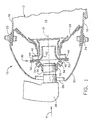
- Figure 2 is a perspective view of the swirler assembly of Figure 1 with the primary swirler removed.
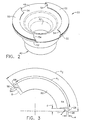
- Figure 3 is a plan view of a retainer segment of Figure 2.
- Figure 4 is an axial sectional view illustrating an alternative embodiment of a swirler assembly.
-
- Referring to the drawings wherein identical reference numerals denote the same elements throughout the various views, Figure 1 shows the forward end of a
combustor 10 of the type suitable for use in a gas turbine engine and including ahollow body 12 defining acombustion chamber 14 therein. Thehollow body 12 is generally annular in form and is defined by anouter liner 16 and aninner liner 18. The upstream end of thehollow body 12 is substantially closed off by acowl 20 attached to theouter liner 16 by afirst fastener 22 and to theinner liner 18 by asecond fastener 24. At least one opening 26 is formed in thecowl 20 for the introduction of fuel and compressed air. The compressed air is introduced into thecombustor 10 from a compressor (not shown) in a direction generally indicated by arrow A of Figure 1. The compressed air passes primarily through theopening 26 to support combustion and partially into the region surrounding thehollow body 12 where it is used to cool both theliners - Disposed between and interconnecting the outer and
inner liners annular dome plate 28. A plurality of circumferentially spaced swirler assemblies 30 (only one shown in Figure 1) is mounted in thedome plate 28. Eachswirler assembly 30 includes aprimary swirler 32 that comprises a plurality of angularly directedpassages 34. Thepassages 34 are angled with respect to theaxial centerline 31 of theswirler assembly 30 so as to impart a swirling motion to the airflow. Theprimary swirler 32 also has anintegral ferrule 36 that coaxially receives afuel nozzle 38. - The
swirler assembly 30 further includes asecondary swirler 40 that adjoins theprimary swirler 32, downstream thereof, and is fixedly received in thedome plate 28. Thesecondary swirler 40 includes aventuri 42 and a plurality of circumferentially spacedswirl vanes 44 disposed coaxially about theventuri 42. Theventuri 42 and theferrule 36 of theprimary swirler 32 are both coaxially aligned with theaxial centerline 31 of theswirler assembly 30. Air from the opening 26 passes through thepassages 34. The swirling air exiting thepassages 34 interacts with fuel injected from thefuel nozzle 38 so as to mix as it passes into theventuri 42. The secondary swirl vanes 44 then act to present a swirl of air swirling in the opposite direction that interacts with the fuel/air mixture so as to further atomize the mixture and prepare it for combustion in thecombustion chamber 14. It should be noted that although Figure 1 illustrates the swirler assembly of the present invention in a single annular combustor, the present invention is equally applicable to other types of combustors, including multi-annular combustors. It should also be noted that the present invention is applicable to co-rotating swirler assemblies in addition to the counter-rotating swirler assembly described above. - The
primary swirler 32 comprises abase section 46 having theferrule 36 formed on the forward side thereof. The aftside base section 46 defines a downstream-facing planar surface. Thesecondary swirler 40 comprises abase section 48 that defines an upstream-facing planar surface that slidingly engages the planar surface of theprimary swirler 32 when theswirler assembly 30 is assembled. Theventuri 42 extends axially (with respect to theaxial centerline 31 of the swirler assembly 30) downstream from thesecondary base section 48 and, as mentioned above, theswirl vanes 44 are disposed coaxially about theventuri 42. - The primary and
secondary swirlers retainer segments 50 that are joined to thesecondary swirler 40 on opposite sides of theventuri 42 from one another. Specifically, theretainer segments 50 are joined (preferably by welding) to the upstream-facing planar surface of thesecondary base section 48 and engage thebase section 46 of theprimary swirler 32. Theretainer segments 50 are located so as to prevent relative axial movement of the twoswirlers primary swirler 32 with respect to thesecondary swirler 40. This arrangement allows theprimary swirler 32 to float or move laterally so that theferrule 36 can be coaxially aligned with, and receive, thefuel nozzle 38, but otherwise prevents the twoswirlers swirler assembly 30 is being installed in the engine. The floatingprimary swirler 32 also accommodates relative motion between thefuel nozzle 38 and thedome plate 28 during engine operation. - Referring now to Figure 2, which shows the
swirler assembly 30 with theprimary swirler 32 removed, it is seen that theretainer segments 50 are arcuate members having relatively narrow widths. Eachretainer segment 50 defines an arc that is less than 180 degrees and has radially (with respect to the swirler centerline 31) inner and outer edges that define parallel curves. The radius of curvature of the outer edges closely matches the radius of curvature defined by thebase section 48 of thesecondary swirler 40. Eachretainer segment 50 is joined in a cantilevered fashion to a corresponding one of two curved, axially extendingridges 52 that are formed on the upstream-facing planar surface of thesecondary base section 48. Theridges 52 are situated along the perimeter of the upstream-facing planar surface and are located on opposite sides of theventuri 42 from one another. Theretainer segments 50 are positioned so that their outer edges are substantially flush with the outer edge of thesecondary base section 48. - The
retainer segments 50 are provided with scalloped ends. That is, each end has aconcave cutout 54 formed therein such that the inner edge of theretainer segment 50 defines an arc A1 that is less than the arc A2 defined by the outer edge, as seen in Figure 3. In one preferred geometry, eachcutout 54 has a curved portion and a straight portion adjacent to the inner edge and defines atip 56 at the outer corner of theretainer segments 50. The width w of thetips 56 is preferably equal to the width of theridges 52 on thesecondary swirler 40. The scalloped ends reduce the weld joint and bending stresses that occur from the forced vibration of the cantileveredretainer segments 50. Thecurved cutouts 54 also reduce the stress concentration factor at the corners of theretainer segments 50, which is where most cracks historically initiate in conventional retainer segments. The scalloped ends also alter the resonant frequency of theretainer segments 50 slightly, which may have a positive impact on the weld joint and bending stresses. - The size of the
concave cutouts 54 should be large enough to adequately alleviate the weld joint and bending stresses. Preferably, thecutouts 54 are sized so as to define an end region 58 (i.e., the portion of theretainer segment 50 in which thecutout 54 is formed) that defines an area A (Figure 3) which is less than the area B defined by thecutout 54. In one preferred embodiment, theretainer segment 50 is sized such that the outer edge has a radius of curvature of about 3.2 centimeters and the inner edge has a radius of curvature of about 2.4 centimeters. Eachtip 56 has a width w of about 0.1 centimeters. Eachconcave cutout 54 has a depth d of about 0.25 centimeters and a curved portion defining a radius r of about 0.5 centimeters. - The smaller
retainer end regions 58 improves the weld prep for welding theretainer segments 50 to theridges 52. Because less material is present at theend regions 58, the material is "consumed" better during welding. The weld joint is thus generally stronger at the ends and lacks discontinuities or crack starters. This strengthens the joint at the end regions, which, as mentioned above, is where cracks usually occur in conventional retainer segments. Preferably, the weld joint is a 100% penetration weld along the entire length of theretainer segments 50, as opposed to the approximately 70% penetration weld commonly used with conventional retainer segments. - The
retainer segments 50 are preferably made of a high temperature alloy suited for use in the turbine section of a gas turbine engine, such as nickel-base or cobalt-base alloys. One commercially available material that is particularly preferred because of its resistance to high cycle fatigue is the nickel-base alloy Hastalloy X. The thickness of theretainer segments 50 will be determined by the application and should be such that the resonant frequency of theretainer segments 50 is out of the operating frequency range of the engine. Typically, theretainer segments 50 will be somewhat thicker than conventional retainer segments to add stiffness and strength. - Figure 4 illustrates an
alternative swirler assembly 130 in which aprimary swirler 132 and asecondary swirler 140 are integrally formed as aunitary swirler body 160 that is fixedly received in adome plate 128. Theprimary swirler 132 includes a first plurality of circumferentially spacedswirl vanes 134 disposed about a central opening, and thesecondary swirler 140 includes aventuri 142 and a second plurality of circumferentially spaced swirl vanes 144 disposed coaxially about theventuri 142. As in the first embodiment, incoming air passing through thefirst swirl vanes 134 is swirled into theventuri 142. This swirling air interacts with fuel injected from a fuel nozzle (not shown in Figure 4) so as to mix as it passes into theventuri 142. The secondary swirl vanes 144 then act to present a swirl of air swirling in the same or opposite direction that interacts with the fuel/air mixture so as to further atomize the mixture. - The
swirler assembly 130 includes aseparate ferrule 136 that is mounted to the forward end of theswirler body 160 to receive the fuel nozzle. Theferrule 136 includes a downstream-facing planar surface that slidingly engages an upstream-facing planar surface theswirler body 160. Theferrule 136 is maintained in sliding engagement with theswirler body 160 by tworetainer segments 150 that are joined to theswirler body 160 on opposite sides thereof. Specifically, theretainer segments 150 are joined (preferably by welding) in a cantilevered fashion to tworidges 152 formed on the upstream-facing planar surface of theswirler body 160. Theretainer segments 150 engage theferrule 136 so as to prevent relative axial movement of theferrule 136 and theswirler body 160 but permit limited lateral movement of theferrule 136 with respect to theswirler body 160. This arrangement allows theferrule 136 to float or move laterally so that it can receive the fuel nozzle, but otherwise prevents theferrule 136 and theswirler body 160 from becoming disengaged while theswirler assembly 130 is being installed in the engine. The floatingferrule 136 also accommodates relative motion between the fuel nozzle and thedome plate 128 during engine operation. - The
retainer segments 150 are the same as the retainer segments described above and shown in Figure 3 in that they are curved pieces having scalloped ends. Each end has a concave cutout formed therein such that the inner edge of theretainer segment 150 defines an arc that is less than the arc defined by the outer edge. The scalloped ends reduce the weld joint and bending stresses that occur from the forced vibration of the cantileveredretainer segments 150 in the same manner as described above in connection with the first embodiment. - The foregoing has described an improved swirler assembly having more durable retainer segments.
Claims (12)
- A retainer segment (50) for a swirler assembly (30) in a gas turbine engine, said retainer segment (50) comprising an arcuate member defining inner and outer curved edges and first and second ends, wherein each end has a concave cutout (54) formed therein.
- The retainer segment (50) of claim 1 wherein said inner edge defines a first arc and said outer edge defines a second arc, said first arc being smaller than said second arc.
- The retainer segment (50) of claim 1 wherein each end of said retainer segment (50) has an end region (58) that defines a first area and each cutout (54) defines a second area, said first area being less than said second area.
- A swirler assembly (30) comprising:a first member (32,36);a second member (40,160) disposed in sliding engagement with said first member (32,36); andat least one retainer segment (50) joined to said second member (40,160) and engaging said first member (32,36), wherein said retainer segment (50) is an arcuate member defining inner and outer curved edges and first and second ends, and each end has a concave cutout (54) formed therein.
- The swirler assembly (30) of claim 4 wherein said inner edge defines a first arc and said outer edge defines a second arc, said first arc being smaller than said second arc.
- The swirler assembly (30) of claim 4 wherein each end of said retainer segment (50) has an end region (58) that defines a first area and each cutout (54) defines a second area, said first area being less than said second area.
- The swirler assembly (30) of claim 4 wherein said second member (40,160) has a perimeter and a ridge formed thereon, along said perimeter, said retainer segment (50) being welded to said ridge in a cantilevered fashion.
- The swirler assembly (30) of claim 7 wherein said retainer segment (50) is welded to said ridge via a 100% penetration weld.
- The swirler assembly (30) of claim 4 further comprising a second retainer segment (50) joined to said second member (40,160) and engaging said first member (32,36), wherein said second retainer segment (50) is an arcuate member defining inner and outer curved edges and first and second ends, and each end has a concave cutout (54) formed therein.
- The swirler assembly (30) of claim 9 wherein said second retainer segment (50) is located on an opposite side of said second member (40,160) from said first-mentioned retainer segment (50).
- The swirler assembly (30) of claim 4 wherein said first member (32,36) is a primary swirler (32) and said second member (40,160) is a secondary swirler(40).
- The swirler assembly (30) of claim 4 wherein said first member (32,36) is a ferrule (36) and said second member (40,160) is a swirler body (160).
Applications Claiming Priority (2)
| Application Number | Priority Date | Filing Date | Title |
|---|---|---|---|
| US09/575,415 US6427435B1 (en) | 2000-05-20 | 2000-05-20 | Retainer segment for swirler assembly |
| US575415 | 2000-05-20 |
Publications (3)
| Publication Number | Publication Date |
|---|---|
| EP1158246A2 true EP1158246A2 (en) | 2001-11-28 |
| EP1158246A3 EP1158246A3 (en) | 2002-01-09 |
| EP1158246B1 EP1158246B1 (en) | 2005-04-27 |
Family
ID=24300231
Family Applications (1)
| Application Number | Title | Priority Date | Filing Date |
|---|---|---|---|
| EP01304218A Expired - Lifetime EP1158246B1 (en) | 2000-05-20 | 2001-05-11 | Retainer segment for swirler assembly |
Country Status (8)
| Country | Link |
|---|---|
| US (1) | US6427435B1 (en) |
| EP (1) | EP1158246B1 (en) |
| JP (1) | JP4753491B2 (en) |
| AU (1) | AU782341B2 (en) |
| BR (1) | BR0102059B1 (en) |
| DE (1) | DE60110309T2 (en) |
| NO (1) | NO330389B1 (en) |
| SG (1) | SG94817A1 (en) |
Cited By (7)
| Publication number | Priority date | Publication date | Assignee | Title |
|---|---|---|---|---|
| EP1508743A2 (en) | 2003-08-19 | 2005-02-23 | General Electric Company | Combuster swirler assembly |
| EP1408279A3 (en) * | 2002-08-22 | 2005-05-11 | General Electric Company | Combustor dome for gas turbine engine |
| DE102005022772A1 (en) * | 2005-05-12 | 2007-01-11 | Universität Karlsruhe | Burner with partial premixing and pre-evaporation of the liquid fuel |
| EP1840467A1 (en) * | 2006-03-30 | 2007-10-03 | Snecma | Device for injecting a mix of air and fuel, combustion chamber and turbomachine equipped with such a device |
| EP1873456A1 (en) | 2006-06-29 | 2008-01-02 | Snecma | Device for injecting a mix of air and fuel, combustion chamber and turbomachine equipped with such a device |
| FR3034844A1 (en) * | 2015-04-09 | 2016-10-14 | Rolls Royce Plc | |
| FR3042588A1 (en) * | 2015-10-16 | 2017-04-21 | Snecma | INJECTION DEVICE FOR A COMBUSTION CHAMBER OF A TURBOMACHINE |
Families Citing this family (26)
| Publication number | Priority date | Publication date | Assignee | Title |
|---|---|---|---|---|
| FR2827367B1 (en) * | 2001-07-16 | 2003-10-17 | Snecma Moteurs | AEROMECHANICAL INJECTION SYSTEM WITH ANTI-RETURN PRIMARY LOCK |
| US6862889B2 (en) * | 2002-12-03 | 2005-03-08 | General Electric Company | Method and apparatus to decrease combustor emissions |
| US7062920B2 (en) * | 2003-08-11 | 2006-06-20 | General Electric Company | Combustor dome assembly of a gas turbine engine having a free floating swirler |
| US7121095B2 (en) * | 2003-08-11 | 2006-10-17 | General Electric Company | Combustor dome assembly of a gas turbine engine having improved deflector plates |
| US6976363B2 (en) * | 2003-08-11 | 2005-12-20 | General Electric Company | Combustor dome assembly of a gas turbine engine having a contoured swirler |
| JP2005076982A (en) * | 2003-08-29 | 2005-03-24 | Mitsubishi Heavy Ind Ltd | Gas turbine combustor |
| US7013649B2 (en) * | 2004-05-25 | 2006-03-21 | General Electric Company | Gas turbine engine combustor mixer |
| US6993916B2 (en) * | 2004-06-08 | 2006-02-07 | General Electric Company | Burner tube and method for mixing air and gas in a gas turbine engine |
| US7140189B2 (en) * | 2004-08-24 | 2006-11-28 | Pratt & Whitney Canada Corp. | Gas turbine floating collar |
| US7134286B2 (en) * | 2004-08-24 | 2006-11-14 | Pratt & Whitney Canada Corp. | Gas turbine floating collar arrangement |
| US7316117B2 (en) * | 2005-02-04 | 2008-01-08 | Siemens Power Generation, Inc. | Can-annular turbine combustors comprising swirler assembly and base plate arrangements, and combinations |
| US7581402B2 (en) * | 2005-02-08 | 2009-09-01 | Siemens Energy, Inc. | Turbine engine combustor with bolted swirlers |
| US7513098B2 (en) | 2005-06-29 | 2009-04-07 | Siemens Energy, Inc. | Swirler assembly and combinations of same in gas turbine engine combustors |
| US7415826B2 (en) * | 2005-07-25 | 2008-08-26 | General Electric Company | Free floating mixer assembly for combustor of a gas turbine engine |
| US20070119052A1 (en) * | 2005-11-28 | 2007-05-31 | General Electric Company | Combustor dome repair method |
| FR2903169B1 (en) * | 2006-06-29 | 2011-11-11 | Snecma | DEVICE FOR INJECTING A MIXTURE OF AIR AND FUEL, COMBUSTION CHAMBER AND TURBOMACHINE HAVING SUCH A DEVICE |
| US7765809B2 (en) * | 2006-11-10 | 2010-08-03 | General Electric Company | Combustor dome and methods of assembling such |
| FR2908867B1 (en) * | 2006-11-16 | 2012-06-15 | Snecma | DEVICE FOR INJECTING A MIXTURE OF AIR AND FUEL, COMBUSTION CHAMBER AND TURBOMACHINE HAVING SUCH A DEVICE |
| US7926280B2 (en) * | 2007-05-16 | 2011-04-19 | Pratt & Whitney Canada Corp. | Interface between a combustor and fuel nozzle |
| EP2078898A1 (en) * | 2008-01-11 | 2009-07-15 | Siemens Aktiengesellschaft | Burner and method for reducing self-induced flame oscillations |
| GB2470742B (en) * | 2009-06-03 | 2011-04-20 | Rolls Royce Plc | Fuel injector for a gas turbine engine |
| US8689563B2 (en) * | 2009-07-13 | 2014-04-08 | United Technologies Corporation | Fuel nozzle guide plate mistake proofing |
| US8272224B2 (en) * | 2009-11-02 | 2012-09-25 | General Electric Company | Apparatus and methods for fuel nozzle frequency adjustment |
| KR101814096B1 (en) * | 2010-02-23 | 2018-01-02 | 아사히 유키자이 가부시키가이샤 | In-line Fluid Mixing Device |
| US8726669B2 (en) * | 2011-06-30 | 2014-05-20 | General Electric Company | Combustor dome with combined deflector/mixer retainer |
| US10253976B2 (en) | 2017-04-24 | 2019-04-09 | United Technologies Corporation | Fuel swirler with anti-rotation features |
Citations (3)
| Publication number | Priority date | Publication date | Assignee | Title |
|---|---|---|---|---|
| US4584834A (en) * | 1982-07-06 | 1986-04-29 | General Electric Company | Gas turbine engine carburetor |
| EP0550953A1 (en) * | 1992-01-02 | 1993-07-14 | General Electric Company | Integral combustor cowl plate/ferrule retainer |
| US6035645A (en) * | 1996-09-26 | 2000-03-14 | Societe National D'etude Et De Construction De Moteurs D'aviation "S.N.E.C.M.A." | Aerodynamic fuel injection system for a gas turbine engine |
Family Cites Families (8)
| Publication number | Priority date | Publication date | Assignee | Title |
|---|---|---|---|---|
| US3853273A (en) * | 1973-10-01 | 1974-12-10 | Gen Electric | Axial swirler central injection carburetor |
| US4454711A (en) * | 1981-10-29 | 1984-06-19 | Avco Corporation | Self-aligning fuel nozzle assembly |
| US4870818A (en) * | 1986-04-18 | 1989-10-03 | United Technologies Corporation | Fuel nozzle guide structure and retainer for a gas turbine engine |
| US5117637A (en) * | 1990-08-02 | 1992-06-02 | General Electric Company | Combustor dome assembly |
| JPH04303134A (en) * | 1991-03-29 | 1992-10-27 | Honda Motor Co Ltd | Gas turbine engine |
| US5399053A (en) * | 1993-04-27 | 1995-03-21 | Avibank Mfg., Inc. | Quick action panel fastener assembly including a cup enclosed retainer receiving a bolt therein |
| US5463864A (en) * | 1993-12-27 | 1995-11-07 | United Technologies Corporation | Fuel nozzle guide for a gas turbine engine combustor |
| US6550251B1 (en) * | 1997-12-18 | 2003-04-22 | General Electric Company | Venturiless swirl cup |
-
2000
- 2000-05-20 US US09/575,415 patent/US6427435B1/en not_active Expired - Lifetime
-
2001
- 2001-05-11 DE DE60110309T patent/DE60110309T2/en not_active Expired - Lifetime
- 2001-05-11 EP EP01304218A patent/EP1158246B1/en not_active Expired - Lifetime
- 2001-05-14 SG SG200102870A patent/SG94817A1/en unknown
- 2001-05-18 AU AU46053/01A patent/AU782341B2/en not_active Ceased
- 2001-05-18 JP JP2001148555A patent/JP4753491B2/en not_active Expired - Fee Related
- 2001-05-18 NO NO20012450A patent/NO330389B1/en not_active IP Right Cessation
- 2001-05-21 BR BRPI0102059-5A patent/BR0102059B1/en not_active IP Right Cessation
Patent Citations (3)
| Publication number | Priority date | Publication date | Assignee | Title |
|---|---|---|---|---|
| US4584834A (en) * | 1982-07-06 | 1986-04-29 | General Electric Company | Gas turbine engine carburetor |
| EP0550953A1 (en) * | 1992-01-02 | 1993-07-14 | General Electric Company | Integral combustor cowl plate/ferrule retainer |
| US6035645A (en) * | 1996-09-26 | 2000-03-14 | Societe National D'etude Et De Construction De Moteurs D'aviation "S.N.E.C.M.A." | Aerodynamic fuel injection system for a gas turbine engine |
Cited By (15)
| Publication number | Priority date | Publication date | Assignee | Title |
|---|---|---|---|---|
| EP1408279A3 (en) * | 2002-08-22 | 2005-05-11 | General Electric Company | Combustor dome for gas turbine engine |
| EP1508743A2 (en) | 2003-08-19 | 2005-02-23 | General Electric Company | Combuster swirler assembly |
| US7104066B2 (en) | 2003-08-19 | 2006-09-12 | General Electric Company | Combuster swirler assembly |
| EP1508743A3 (en) * | 2003-08-19 | 2013-01-16 | General Electric Company | Combuster swirler assembly |
| DE102005022772A1 (en) * | 2005-05-12 | 2007-01-11 | Universität Karlsruhe | Burner with partial premixing and pre-evaporation of the liquid fuel |
| CN101046298B (en) * | 2006-03-30 | 2010-06-23 | 斯奈克玛 | Apparatus to inject a mixture of air and fuel, combustion chamber and turbine engine equipped with such an apparatus |
| US7721545B2 (en) | 2006-03-30 | 2010-05-25 | Snecma | Device for injecting a mixture of air and fuel, combustion chamber and turbomachine both equipped with such a device |
| FR2899314A1 (en) * | 2006-03-30 | 2007-10-05 | Snecma Sa | DEVICE FOR INJECTING A MIXTURE OF AIR AND FUEL, COMBUSTION CHAMBER AND TURBOMACHINE HAVING SUCH A DEVICE |
| EP1840467A1 (en) * | 2006-03-30 | 2007-10-03 | Snecma | Device for injecting a mix of air and fuel, combustion chamber and turbomachine equipped with such a device |
| EP1873456A1 (en) | 2006-06-29 | 2008-01-02 | Snecma | Device for injecting a mix of air and fuel, combustion chamber and turbomachine equipped with such a device |
| FR2903170A1 (en) * | 2006-06-29 | 2008-01-04 | Snecma Sa | DEVICE FOR INJECTING A MIXTURE OF AIR AND FUEL, COMBUSTION CHAMBER AND TURBOMACHINE HAVING SUCH A DEVICE |
| US7908865B2 (en) | 2006-06-29 | 2011-03-22 | Snecma | Device for injecting a mixture of air and fuel, and combustion chamber and turbomachine provided with such a device |
| FR3034844A1 (en) * | 2015-04-09 | 2016-10-14 | Rolls Royce Plc | |
| US10190776B2 (en) | 2015-04-09 | 2019-01-29 | Rolls-Royce Plc | Fuel injector system |
| FR3042588A1 (en) * | 2015-10-16 | 2017-04-21 | Snecma | INJECTION DEVICE FOR A COMBUSTION CHAMBER OF A TURBOMACHINE |
Also Published As
| Publication number | Publication date |
|---|---|
| NO20012450D0 (en) | 2001-05-18 |
| JP4753491B2 (en) | 2011-08-24 |
| SG94817A1 (en) | 2003-03-18 |
| JP2002071134A (en) | 2002-03-08 |
| EP1158246A3 (en) | 2002-01-09 |
| EP1158246B1 (en) | 2005-04-27 |
| DE60110309T2 (en) | 2006-02-16 |
| AU782341B2 (en) | 2005-07-21 |
| US6427435B1 (en) | 2002-08-06 |
| BR0102059B1 (en) | 2009-05-05 |
| DE60110309D1 (en) | 2005-06-02 |
| NO20012450L (en) | 2001-11-21 |
| NO330389B1 (en) | 2011-04-04 |
| AU4605301A (en) | 2001-11-22 |
| BR0102059A (en) | 2001-12-18 |
Similar Documents
| Publication | Publication Date | Title |
|---|---|---|
| EP1158246B1 (en) | Retainer segment for swirler assembly | |
| EP1508743B1 (en) | Combuster swirler assembly | |
| US5117637A (en) | Combustor dome assembly | |
| JP4630520B2 (en) | Hybrid film cooled combustor liner | |
| US6408629B1 (en) | Combustor liner having preferentially angled cooling holes | |
| US7316117B2 (en) | Can-annular turbine combustors comprising swirler assembly and base plate arrangements, and combinations | |
| US6314739B1 (en) | Brazeless combustor dome assembly | |
| CA2528808C (en) | Method and apparatus for decreasing combustor acoustics | |
| US8261554B2 (en) | Fuel nozzle tip assembly | |
| EP1116918B1 (en) | Combustor swirler assembly | |
| EP0476927A2 (en) | Fuel injector nozzle support | |
| US7131273B2 (en) | Gas turbine engine carburetor with flat retainer connecting primary and secondary swirlers | |
| US6735950B1 (en) | Combustor dome plate and method of making the same | |
| US6779268B1 (en) | Outer and inner cowl-wire wrap to one piece cowl conversion | |
| US6467272B1 (en) | Means for wear reduction in a gas turbine combustor | |
| AU2002247476A1 (en) | Means for wear reduction in a gas turbine combustor |
Legal Events
| Date | Code | Title | Description |
|---|---|---|---|
| PUAI | Public reference made under article 153(3) epc to a published international application that has entered the european phase |
Free format text: ORIGINAL CODE: 0009012 |
|
| PUAL | Search report despatched |
Free format text: ORIGINAL CODE: 0009013 |
|
| AK | Designated contracting states |
Kind code of ref document: A2 Designated state(s): AT BE CH CY DE DK ES FI FR GB GR IE IT LI LU MC NL PT SE TR Kind code of ref document: A2 Designated state(s): DE FR GB IT SE |
|
| AX | Request for extension of the european patent |
Free format text: AL;LT;LV;MK;RO;SI |
|
| AK | Designated contracting states |
Kind code of ref document: A3 Designated state(s): AT BE CH CY DE DK ES FI FR GB GR IE IT LI LU MC NL PT SE TR |
|
| AX | Request for extension of the european patent |
Free format text: AL;LT;LV;MK;RO;SI |
|
| RIC1 | Information provided on ipc code assigned before grant |
Free format text: 7F 23R 3/14 A, 7F 23R 3/60 B |
|
| 17P | Request for examination filed |
Effective date: 20020709 |
|
| AKX | Designation fees paid |
Free format text: DE FR GB IT SE |
|
| GRAP | Despatch of communication of intention to grant a patent |
Free format text: ORIGINAL CODE: EPIDOSNIGR1 |
|
| GRAS | Grant fee paid |
Free format text: ORIGINAL CODE: EPIDOSNIGR3 |
|
| GRAA | (expected) grant |
Free format text: ORIGINAL CODE: 0009210 |
|
| AK | Designated contracting states |
Kind code of ref document: B1 Designated state(s): DE FR GB IT SE |
|
| REG | Reference to a national code |
Ref country code: GB Ref legal event code: FG4D |
|
| REG | Reference to a national code |
Ref country code: IE Ref legal event code: FG4D |
|
| REF | Corresponds to: |
Ref document number: 60110309 Country of ref document: DE Date of ref document: 20050602 Kind code of ref document: P |
|
| REG | Reference to a national code |
Ref country code: SE Ref legal event code: TRGR |
|
| PLBE | No opposition filed within time limit |
Free format text: ORIGINAL CODE: 0009261 |
|
| STAA | Information on the status of an ep patent application or granted ep patent |
Free format text: STATUS: NO OPPOSITION FILED WITHIN TIME LIMIT |
|
| ET | Fr: translation filed | ||
| 26N | No opposition filed |
Effective date: 20060130 |
|
| PG25 | Lapsed in a contracting state [announced via postgrant information from national office to epo] |
Ref country code: IT Free format text: LAPSE BECAUSE OF NON-PAYMENT OF DUE FEES Effective date: 20120511 |
|
| PGFP | Annual fee paid to national office [announced via postgrant information from national office to epo] |
Ref country code: IT Payment date: 20120524 Year of fee payment: 12 |
|
| PGRI | Patent reinstated in contracting state [announced from national office to epo] |
Ref country code: IT Effective date: 20131025 |
|
| PG25 | Lapsed in a contracting state [announced via postgrant information from national office to epo] |
Ref country code: IT Free format text: LAPSE BECAUSE OF NON-PAYMENT OF DUE FEES Effective date: 20140511 |
|
| REG | Reference to a national code |
Ref country code: FR Ref legal event code: PLFP Year of fee payment: 16 |
|
| PGFP | Annual fee paid to national office [announced via postgrant information from national office to epo] |
Ref country code: DE Payment date: 20160527 Year of fee payment: 16 Ref country code: GB Payment date: 20160527 Year of fee payment: 16 |
|
| PGFP | Annual fee paid to national office [announced via postgrant information from national office to epo] |
Ref country code: SE Payment date: 20160527 Year of fee payment: 16 Ref country code: FR Payment date: 20160530 Year of fee payment: 16 |
|
| REG | Reference to a national code |
Ref country code: DE Ref legal event code: R119 Ref document number: 60110309 Country of ref document: DE |
|
| REG | Reference to a national code |
Ref country code: SE Ref legal event code: EUG |
|
| GBPC | Gb: european patent ceased through non-payment of renewal fee |
Effective date: 20170511 |
|
| PG25 | Lapsed in a contracting state [announced via postgrant information from national office to epo] |
Ref country code: SE Free format text: LAPSE BECAUSE OF NON-PAYMENT OF DUE FEES Effective date: 20170512 |
|
| REG | Reference to a national code |
Ref country code: FR Ref legal event code: ST Effective date: 20180131 |
|
| PG25 | Lapsed in a contracting state [announced via postgrant information from national office to epo] |
Ref country code: GB Free format text: LAPSE BECAUSE OF NON-PAYMENT OF DUE FEES Effective date: 20170511 Ref country code: DE Free format text: LAPSE BECAUSE OF NON-PAYMENT OF DUE FEES Effective date: 20171201 |
|
| PG25 | Lapsed in a contracting state [announced via postgrant information from national office to epo] |
Ref country code: FR Free format text: LAPSE BECAUSE OF NON-PAYMENT OF DUE FEES Effective date: 20170531 |