EP1158156B1 - Fluidic nozzle control system - Google Patents
Fluidic nozzle control system Download PDFInfo
- Publication number
- EP1158156B1 EP1158156B1 EP01304570A EP01304570A EP1158156B1 EP 1158156 B1 EP1158156 B1 EP 1158156B1 EP 01304570 A EP01304570 A EP 01304570A EP 01304570 A EP01304570 A EP 01304570A EP 1158156 B1 EP1158156 B1 EP 1158156B1
- Authority
- EP
- European Patent Office
- Prior art keywords
- flow
- nozzle
- chamber
- control system
- inlet
- Prior art date
- Legal status (The legal status is an assumption and is not a legal conclusion. Google has not performed a legal analysis and makes no representation as to the accuracy of the status listed.)
- Expired - Lifetime
Links
Images

Classifications
-
- F—MECHANICAL ENGINEERING; LIGHTING; HEATING; WEAPONS; BLASTING
- F02—COMBUSTION ENGINES; HOT-GAS OR COMBUSTION-PRODUCT ENGINE PLANTS
- F02K—JET-PROPULSION PLANTS
- F02K1/00—Plants characterised by the form or arrangement of the jet pipe or nozzle; Jet pipes or nozzles peculiar thereto
- F02K1/002—Plants characterised by the form or arrangement of the jet pipe or nozzle; Jet pipes or nozzles peculiar thereto with means to modify the direction of thrust vector
-
- F—MECHANICAL ENGINEERING; LIGHTING; HEATING; WEAPONS; BLASTING
- F02—COMBUSTION ENGINES; HOT-GAS OR COMBUSTION-PRODUCT ENGINE PLANTS
- F02K—JET-PROPULSION PLANTS
- F02K1/00—Plants characterised by the form or arrangement of the jet pipe or nozzle; Jet pipes or nozzles peculiar thereto
- F02K1/28—Plants characterised by the form or arrangement of the jet pipe or nozzle; Jet pipes or nozzles peculiar thereto using fluid jets to influence the jet flow
- F02K1/30—Plants characterised by the form or arrangement of the jet pipe or nozzle; Jet pipes or nozzles peculiar thereto using fluid jets to influence the jet flow for varying effective area of jet pipe or nozzle
-
- F—MECHANICAL ENGINEERING; LIGHTING; HEATING; WEAPONS; BLASTING
- F05—INDEXING SCHEMES RELATING TO ENGINES OR PUMPS IN VARIOUS SUBCLASSES OF CLASSES F01-F04
- F05D—INDEXING SCHEME FOR ASPECTS RELATING TO NON-POSITIVE-DISPLACEMENT MACHINES OR ENGINES, GAS-TURBINES OR JET-PROPULSION PLANTS
- F05D2270/00—Control
- F05D2270/01—Purpose of the control system
- F05D2270/17—Purpose of the control system to control boundary layer
- F05D2270/173—Purpose of the control system to control boundary layer by the Coanda effect
-
- F—MECHANICAL ENGINEERING; LIGHTING; HEATING; WEAPONS; BLASTING
- F05—INDEXING SCHEMES RELATING TO ENGINES OR PUMPS IN VARIOUS SUBCLASSES OF CLASSES F01-F04
- F05D—INDEXING SCHEME FOR ASPECTS RELATING TO NON-POSITIVE-DISPLACEMENT MACHINES OR ENGINES, GAS-TURBINES OR JET-PROPULSION PLANTS
- F05D2270/00—Control
- F05D2270/01—Purpose of the control system
- F05D2270/18—Purpose of the control system using fluidic amplifiers or actuators
-
- Y—GENERAL TAGGING OF NEW TECHNOLOGICAL DEVELOPMENTS; GENERAL TAGGING OF CROSS-SECTIONAL TECHNOLOGIES SPANNING OVER SEVERAL SECTIONS OF THE IPC; TECHNICAL SUBJECTS COVERED BY FORMER USPC CROSS-REFERENCE ART COLLECTIONS [XRACs] AND DIGESTS
- Y02—TECHNOLOGIES OR APPLICATIONS FOR MITIGATION OR ADAPTATION AGAINST CLIMATE CHANGE
- Y02T—CLIMATE CHANGE MITIGATION TECHNOLOGIES RELATED TO TRANSPORTATION
- Y02T50/00—Aeronautics or air transport
- Y02T50/60—Efficient propulsion technologies, e.g. for aircraft
Definitions
- the present invention relates generally to exhaust systems for aircraft gas turbine engines, and in particular to a control system for selectively adjusting effective flow areas of an aircraft engine exhaust nozzle to change operational characteristics of the nozzle.
- High performance advanced aircraft must operate over a wide range of flight conditions while maintaining good fuel efficiency and high maneuverability.
- these aircraft include an exhaust nozzle for each engine that permits variation in exhaust gas flow area.
- the nozzle has a convergent duct, a plane of minimum flow area known as a throat, and a divergent duct ending at a nozzle exit.
- the throat and exit may be varied in size to provide for efficient engine operation at all engine power settings, flight speeds, and altitudes.
- Some variable-area nozzles provide for controllable deflection of the direction of exhaust gas flow, known as thrust vectoring, to enhance aircraft controllability. Thrust vectoring offers the potential of substantial performance benefits and can permit conventional aerodynamic controls, such as tail surfaces, to be reduced in size or eliminated altogether.
- variable-area nozzle requires a complex mechanism that is heavy and costly. It has several moveable flaps with associated linkages and hydraulic actuators. The mechanism adds weight and structural complexity, and requires regular maintenance. Even greater structural weight penalties are incurred to include the variable-area mechanism in nozzles having unconventional shapes, such as wide aspect ratio, elliptical, or diamond. Further, each moveable flap of the variable-area nozzle has edges and surface gaps between adjacent structure that can make the nozzle more visible on radar, which is undesirable for military aircraft.
- the flow areas can be varied fluidically, thereby providing several advantages.
- Effective flow areas in a fluidic nozzle are varied by injecting pressurized air at selected locations along a perimeter of the throat or the divergent duct to constrict area available for exhaust gas, aerodynamically blocking a portion of the flow area.
- the nozzle can be mechanically fixed in geometry, without need for any moveable flaps.
- Nozzle weight is low because there are no actuators or moving parts, and the structure is more efficient.
- the nozzle may have any desired shape and is therefore more easily integrated into a structural design of an aircraft. Surfaces of the nozzle are smooth, without any gaps, permitting improved radar signature.
- a drawback to the fluidic nozzle has been that a complex system of pipes, manifolds, and valves was needed to distribute pressurized air to desired locations. For instance, one type of fluidic nozzle requires three manifolds and nine valves, along with interconnecting pipes to deliver compressor discharge air to various locations. These parts add weight and cost and degrade reliability. Further, the parts must be dispersed about the nozzle and cannot be packaged into one location that is designed for reduced vulnerability to weapons, thus degrading survivability.
- control system for selectively adjusting effective flow areas of an aircraft engine exhaust nozzle to change operational characteristics of the nozzle, wherein the control system comprises:
- a method of controlling an aircraft engine exhaust nozzle characterized in that the nozzle is of the type having fluidic injection capability whereby a first flow of pressurized gas is delivered to the nozzle and injected into an exhaust stream for fluidically varying operational characteristics of the nozzle, the method comprising the step of selectively controlling said injection of the first flow into the exhaust stream using a fluidic control system by injecting a second flow of pressurized gas into the first flow to adjust a distribution of the first flow delivered to the nozzle, so the exhaust stream is controlled fluidically through injection of the first flow and the first flow is controlled fluidically through injection of the second flow.
- a control system for selectively adjusting effective flow areas of an aircraft gas turbine engine exhaust nozzle to change operational characteristics of the nozzle is indicated generally at 11.
- the control system 11 includes an adjustable inlet 13, a chamber 15 having a hollow interior, and a plurality of outlet passages 17. A flow of pressurized air passes sequentially from the inlet 13 into the chamber 15, and then to one or more outlet passages 17.
- the inlet 13 comprises a passage which provides a flow of gas, such as air, to the control system from a source 19 of pressurized air.
- the source 19 is the gas turbine engine, or a suitable air outlet on the engine such as a compressor bleed discharge port (not shown).
- Compressor discharge air has passed through at least a portion of the engine's compressor, elevating the pressure sufficiently to enable propelling the air to any location in the exhaust nozzle with a positive pressure gradient.
- any suitable source or sources of pressurized air can be used, such as a mid-compressor stage bleed or off-take, a fan discharge port of the engine, inlet bypass duct, or independent air circuit, without departing from the scope of this invention.
- the inlet 13 preferably includes a control valve 21 for selectively varying a rate of flow through the inlet.
- the valve 21 can be selectively adjusted by a suitable control system, shown schematically by a T-handle 23 in Fig. 1.
- the selected rate of flow can range from zero to a maximum flow limited by a size of the inlet and the air pressure.
- the valve 21 can be located anywhere along the inlet 13 between the source 19 of air and the chamber 15. However, an inlet that has no control valve is included within the scope of this invention.
- the chamber 15 is a plenum having a cross-sectional size which is larger than the inlet 13, and substantially oversized for the airflow provided from the inlet. Accordingly, the airflow does not expand sufficiently to fill the chamber 15. Rather, the air separates from peripheral walls of the chamber as it flows into and through the chamber. Thus, the airflow forms a free jet of air as it flows into the chamber 15.
- the jet may be directed or steered, as discussed below, toward one or more outlet passages 17 on a downstream end 25 of the chamber.
- the outlet passages 17 comprise targets for the jet.
- the jet can be steered along one side of the chamber 15 or may be steered toward a more central location.
- the chamber 15 may have a cylindrical shape, as shown in the preferred embodiment of Figs. 1 and 2, or another suitable shape without departing from the scope of this invention.
- the outlet passages 17 are disposed about the downstream end 25 of the chamber 15 to permit the jet of air to be steered toward one or more outlet passages.
- the preferred embodiment has eight outlet passages 17.
- the passages are shaped, as seen in Fig. 2, to form adjoining sectors 27 of a circle and sectors 29 of an annulus generally covering the downstream end 25 of the chamber.
- the downstream end 25 may be spherical, concave, convex, flat, or other suitable shapes. There may be any number of outlet passages 17, shapes, arrangements, and locations of outlet passages about the chamber 15, without departing from the scope of this invention.
- a fluidically controlled exhaust nozzle is indicated generally at 31.
- the nozzle 31 may be of any suitable cross-sectional shape, such as circular, rectangular, elliptical, or diamond.
- the nozzle 31 includes a convergent duct 33, a minimum area section or throat 35, and a divergent duct 37.
- Each outlet passage 17 is connected to a site or a region along an inner surface of the exhaust nozzle 31 to provide fluid communication between the chamber 15 and the nozzle. Air passing through the chamber 15 and into one of the outlet passages 17 is conveyed to the corresponding site on the exhaust nozzle 31.
- the sites may include any region of the exhaust nozzle where air is needed.
- eight sites of the preferred embodiment include the upper, lower, left, and right sides of the throat 35 and the upper, lower, left, and right sides of the divergent duct 35 at a location about 80% of the distance from the throat to the exit.
- the air may be conveyed to other site locations and/or a different number of sites without departing from the scope of this invention.
- Each outlet passage 17 has an outflow end 36 (Figs. 3-6) having a suitable flow dispenser, such as a flow guide, exit plate, or distribution manifold.
- the outflow end 36 dispenses the air across the site as desired for injection through the nozzle surface and into the main exhaust flow.
- the outflow end is formed so it does not interfere with cooling air delivered along a nozzle duct liner (not shown), so nozzle cooling is substantially unaffected.
- the throat 35 is defined by the physical limits of the duct wall at the throat.
- fluidic injection reduces effective flow area by blocking a portion of the physical flow area with injected air.
- the area of throat 35 may be reduced to the reheat, nonvectored configuration of Fig. 4 by injecting air that is symmetrically divided between the upper and lower sites.
- the air jet is steered parallel to a central axis 38 in the chamber 15. The jet is targeted to a center of the downstream end 25 of the chamber 15 as shown in Fig. 2, where it will be divided in approximately equal portions among the adjoining sectors 27 of the circle. Those outlet sectors 27 lead to sites generally surrounding the throat 35 of the nozzle.
- Throat area can be decreased further to the dry power, nonvectored configuration of Fig. 3 by injecting a greater quantity of air.
- the jet continues to be steered parallel to the central axis 38 while the valve 21 in the inlet 13 is adjusted to provide an increased amount of pressurized air, thereby decreasing the effective size of the throat 35.
- Thrust vectoring may be achieved by injecting air in a non-symmetrical pattern, as shown in the vectored configurations of Figs. 5 and 6. Air is injected at a site on the lower surface of the divergent duct 37 at a position farther downstream than on the upper surface. Injected air deflects the main exhaust stream and the throat plane becomes skewed, tending to turn the exhaust stream and generating a corresponding angle of thrust force. The magnitude of the thrust force is not substantially reduced by this method of vectoring. To accomplish the Fig. 6 configuration, the jet is steered upwardly in the chamber where it will be divided among the upper sectors 27, 29, as shown on Fig. 2.
- the upper sector 29 of the annulus leads to a site on the divergent duct 37 along the lower side of the nozzle, while the upper sector 27 of the circle leads to a site at the throat 35 along the upper side.
- the Fig. 5 configuration is accomplished with the same steering trajectory as for Fig. 6, but the valve 21 is adjusted to provide an increased amount of pressurized air to decrease the throat 35 to an effective size appropriate for dry power operation.
- the air flow in the chamber 15 may be steered or directed towards one or more of the outlet passages 17.
- the steering preferably occurs generally at a control plane 39 (Fig. 1) located where the flow leaves the inlet 13 and enters the chamber 15, although other locations in the chamber do not depart from the scope of this invention.
- the jet will generally continue along a constant trajectory throughout the chamber 15. For instance, if air is needed in the upper annulus sector 29, air flow entering the chamber 15 is steered toward that sector to deliver air to that outlet passage and corresponding site of the nozzle 31.
- a fluidic method free from mechanical flow deflectors.
- several tabs 41 or plates are mounted about a periphery of the inlet 13 and entrance to chamber 15, generally at the control plane 39.
- the tabs 41 are generally parallel to the walls, forming a channel 43 or series of channels between each tab and the wall.
- Pressurized air known as steering air
- the steering air can be introduced along any selected circumferential portion of the periphery of the inlet.
- the steering air preferably originates from the compressor discharge of the engine 19, although other sources are envisioned.
- the volume of steering air introduced into the channel 43 is significantly less than the volume flowing through the inlet 13. Although a system of ducts and actuated valves (not shown) are required to distribute the steering air to selected injectors 44 about the circumference, the weight and complexity of this system are small because of the small amount of steering air needed.
- Flow through the inlet 13 is steered by injecting steering air at selected circumferential locations about the periphery of the inlet.
- the inlet flow is turned partially by a mechanism known to those skilled in the art as Coanda Effect turning.
- the Coanda Effect is a natural tendency of fluids to adhere to and be deflected by a surface nearly tangential to the flow path.
- the steering air from the channel 43 flows generally parallel to a wall of the chamber 15 at a high velocity, producing a low static pressure which draws the jet traveling out of the inlet 13 toward the wall of the chamber. Steering air mixes with the jet and turns inlet flow parallel to the direction of motion of the steering flow.
- the jet in order to steer the jet upwardly, steering air is introduced into a channel 43 along an upper portion of the circumference of the inlet 13.
- steering air is introduced into a channel 43 along a lower portion of the circumference of the inlet 13.
- the jet can be directed to adhere to one wall of the chamber 15, such as an extreme upper or left side surface. It is expected that by proper distribution of the steering air among the channels 43 about the circumference of the inlet 13, the jet can be selectively directed to any angle between the walls, anywhere within the interior of the chamber 15, with reasonable degree of accuracy.
- a second embodiment of the present invention also steers the flow fluidically. It includes a porous surface 45 or porous wall about the periphery of the inlet 13 and entrance to the chamber 15, generally at the control plane 39.
- a vacuum or suction is applied through the porous surface 45 to draw the inlet air flow generally laterally to a selected trajectory.
- a stream of steering air may be injected, indicated by arrow 47, to further push the flow.
- the injected stream 47 is generally diametrically opposite to the applied suction and generally perpendicular to the inlet air flow.
- a combination of suction and opposite injection may be applied, or either suction or injection may be applied separately. It is expected that application of suction and/or opposed injection at suitable strengths and locations can steer the jet to any angle within the interior of the chamber 15 with a reasonable degree of accuracy.
- the control system 11 permits selective distribution of pressurized air along the inner surface of the exhaust nozzle 31.
- the control valve 21 in the inlet 13 is adjusted to vary the amount of flow that is fluidically injected to block the physical flow area.
- the jet is steered in the chamber 15 to outlet passages 17 leading to sites at the throat 35 of the nozzle, with the flow being symmetrically distributed about the throat.
- the flow is steered to a new combination of outlet passages 17 within the chamber. Those outlet passages distribute the flow to sites that are not symmetric about the nozzle 31, thereby changing the direction of the exhaust stream.
- the jet in the chamber 15 may be steered to go entirely to one site in the nozzle 31, or it may be split among two or more sites in desired proportions. Steering is accomplished by one of several methods, preferably by changing the distribution of the small quantity of steering air.
- the fluidic control embodiments of the present invention achieve control of a fluidic exhaust nozzle using a fluidic device.
- the system functions like a double flow amplifier.
- the small quantity of steering air flow controls a greater quantity of inlet air flow, which in turn controls an even greater quantity of the main exhaust flow.
- the invention provides a control system for selectively adjusting effective flow areas of an aircraft engine exhaust nozzle to change operational characteristics of the nozzle.
- the adjustable inlet 13 and chamber 15 result in lower weight, fewer parts, and reduced cost relative to fluidic nozzles of the prior art.
- the parts of the present invention, most of which are at the chamber 15, are readily packaged into one location in the aircraft to facilitate reduced vulnerability.
Description
- The present invention relates generally to exhaust systems for aircraft gas turbine engines, and in particular to a control system for selectively adjusting effective flow areas of an aircraft engine exhaust nozzle to change operational characteristics of the nozzle.
- High performance advanced aircraft must operate over a wide range of flight conditions while maintaining good fuel efficiency and high maneuverability. Typically, these aircraft include an exhaust nozzle for each engine that permits variation in exhaust gas flow area. The nozzle has a convergent duct, a plane of minimum flow area known as a throat, and a divergent duct ending at a nozzle exit. The throat and exit may be varied in size to provide for efficient engine operation at all engine power settings, flight speeds, and altitudes. Some variable-area nozzles provide for controllable deflection of the direction of exhaust gas flow, known as thrust vectoring, to enhance aircraft controllability. Thrust vectoring offers the potential of substantial performance benefits and can permit conventional aerodynamic controls, such as tail surfaces, to be reduced in size or eliminated altogether.
- Unfortunately, a variable-area nozzle requires a complex mechanism that is heavy and costly. It has several moveable flaps with associated linkages and hydraulic actuators. The mechanism adds weight and structural complexity, and requires regular maintenance. Even greater structural weight penalties are incurred to include the variable-area mechanism in nozzles having unconventional shapes, such as wide aspect ratio, elliptical, or diamond. Further, each moveable flap of the variable-area nozzle has edges and surface gaps between adjacent structure that can make the nozzle more visible on radar, which is undesirable for military aircraft.
- As an alternative to mechanized variation of the physical boundaries of the throat and exit, the flow areas can be varied fluidically, thereby providing several advantages. Effective flow areas in a fluidic nozzle are varied by injecting pressurized air at selected locations along a perimeter of the throat or the divergent duct to constrict area available for exhaust gas, aerodynamically blocking a portion of the flow area. As a result, the nozzle can be mechanically fixed in geometry, without need for any moveable flaps. Nozzle weight is low because there are no actuators or moving parts, and the structure is more efficient. The nozzle may have any desired shape and is therefore more easily integrated into a structural design of an aircraft. Surfaces of the nozzle are smooth, without any gaps, permitting improved radar signature.
- In US-A-3,420,060 there is described a control system for selectively adjusting effective flow areas of an aircraft engine exhaust nozzle generally in accordance with the preamble of claim 1.
- A drawback to the fluidic nozzle has been that a complex system of pipes, manifolds, and valves was needed to distribute pressurized air to desired locations. For instance, one type of fluidic nozzle requires three manifolds and nine valves, along with interconnecting pipes to deliver compressor discharge air to various locations. These parts add weight and cost and degrade reliability. Further, the parts must be dispersed about the nozzle and cannot be packaged into one location that is designed for reduced vulnerability to weapons, thus degrading survivability.
- According to the present invention, there is provided a control system for selectively adjusting effective flow areas of an aircraft engine exhaust nozzle to change operational characteristics of the nozzle, wherein the control system comprises:
- a chamber having a hollow interior, an upstream end, and a downstream end;
- a plurality of outlet passages at said downstream end and extending from the hollow interior of the chamber to sites within the exhaust nozzle, and
- an adjustable inlet extending from a pressurized air source to the hollow interior of the chamber at said upstream end for delivering a jet of pressurized air to the chamber, wherein the inlet is adjustable to steer said jet of pressurized air to selected one or more outlet passages of said plurality of outlet passages at said downstream end of the chamber for the delivery of air via said one or more outlets to corresponding one or more sites within the exhaust nozzle thereby to change the operational characteristics of the nozzle, characterised in that
- the adjustable inlet is fluidically controlled, free from mechanical flow deflectors.
- In another aspect of the invention, there is provided a method of controlling an aircraft engine exhaust nozzle characterized in that the nozzle is of the type having fluidic injection capability whereby a first flow of pressurized gas is delivered to the nozzle and injected into an exhaust stream for fluidically varying operational characteristics of the nozzle, the method comprising the step of selectively controlling said injection of the first flow into the exhaust stream using a fluidic control system by injecting a second flow of pressurized gas into the first flow to adjust a distribution of the first flow delivered to the nozzle, so the exhaust stream is controlled fluidically through injection of the first flow and the first flow is controlled fluidically through injection of the second flow.
- Embodiments of the invention will now be described, by way of example, with reference to the accompanying drawings in which:
- Fig. 1 is a schematic elevation of a control system according to the present invention;
- Fig. 2 is a section along line 2-2 of Fig. 1;
- Fig. 3 is a schematic elevation of a fluidic exhaust nozzle at a dry power, nonvectored configuration;
- Fig. 4 is a schematic elevation of the nozzle at a reheat, nonvectored configuration;
- Fig. 5 is a schematic elevation of the nozzle at a dry power, thrust vectored configuration;
- Fig. 6 is a schematic elevation of the nozzle at a reheat, thrust vectored configuration;
- Fig. 7 is a schematic elevation of a channel for injecting steering air into the control system to steer air flow through the system;
- Fig. 8 is a schematic elevation of a second embodiment of a control system for steering flow through the system
- Corresponding reference characters indicate corresponding parts throughout the several views of the drawings.
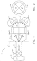
- Referring now to the drawings and in particular to Fig. 1, a control system for selectively adjusting effective flow areas of an aircraft gas turbine engine exhaust nozzle to change operational characteristics of the nozzle is indicated generally at 11. The
control system 11 includes anadjustable inlet 13, achamber 15 having a hollow interior, and a plurality ofoutlet passages 17. A flow of pressurized air passes sequentially from theinlet 13 into thechamber 15, and then to one ormore outlet passages 17. - The
inlet 13 comprises a passage which provides a flow of gas, such as air, to the control system from asource 19 of pressurized air. Preferably, thesource 19 is the gas turbine engine, or a suitable air outlet on the engine such as a compressor bleed discharge port (not shown). Compressor discharge air has passed through at least a portion of the engine's compressor, elevating the pressure sufficiently to enable propelling the air to any location in the exhaust nozzle with a positive pressure gradient. However, any suitable source or sources of pressurized air can be used, such as a mid-compressor stage bleed or off-take, a fan discharge port of the engine, inlet bypass duct, or independent air circuit, without departing from the scope of this invention. - The
inlet 13 preferably includes acontrol valve 21 for selectively varying a rate of flow through the inlet. Thevalve 21 can be selectively adjusted by a suitable control system, shown schematically by a T-handle 23 in Fig. 1. The selected rate of flow can range from zero to a maximum flow limited by a size of the inlet and the air pressure. Thevalve 21 can be located anywhere along theinlet 13 between thesource 19 of air and thechamber 15. However, an inlet that has no control valve is included within the scope of this invention. - The
chamber 15 is a plenum having a cross-sectional size which is larger than theinlet 13, and substantially oversized for the airflow provided from the inlet. Accordingly, the airflow does not expand sufficiently to fill thechamber 15. Rather, the air separates from peripheral walls of the chamber as it flows into and through the chamber. Thus, the airflow forms a free jet of air as it flows into thechamber 15. The jet may be directed or steered, as discussed below, toward one ormore outlet passages 17 on adownstream end 25 of the chamber. - Accordingly, the
outlet passages 17 comprise targets for the jet. The jet can be steered along one side of thechamber 15 or may be steered toward a more central location. Thechamber 15 may have a cylindrical shape, as shown in the preferred embodiment of Figs. 1 and 2, or another suitable shape without departing from the scope of this invention. - The
outlet passages 17 are disposed about thedownstream end 25 of thechamber 15 to permit the jet of air to be steered toward one or more outlet passages. As seen in Fig. 1, the preferred embodiment has eightoutlet passages 17. The passages are shaped, as seen in Fig. 2, to formadjoining sectors 27 of a circle andsectors 29 of an annulus generally covering thedownstream end 25 of the chamber. Thedownstream end 25 may be spherical, concave, convex, flat, or other suitable shapes. There may be any number ofoutlet passages 17, shapes, arrangements, and locations of outlet passages about thechamber 15, without departing from the scope of this invention. - Referring now to Figs. 3-6, a fluidically controlled exhaust nozzle is indicated generally at 31. The
nozzle 31 may be of any suitable cross-sectional shape, such as circular, rectangular, elliptical, or diamond. Thenozzle 31 includes aconvergent duct 33, a minimum area section orthroat 35, and adivergent duct 37. - Each
outlet passage 17 is connected to a site or a region along an inner surface of theexhaust nozzle 31 to provide fluid communication between thechamber 15 and the nozzle. Air passing through thechamber 15 and into one of theoutlet passages 17 is conveyed to the corresponding site on theexhaust nozzle 31. The sites may include any region of the exhaust nozzle where air is needed. For example, eight sites of the preferred embodiment include the upper, lower, left, and right sides of thethroat 35 and the upper, lower, left, and right sides of thedivergent duct 35 at a location about 80% of the distance from the throat to the exit. The air may be conveyed to other site locations and/or a different number of sites without departing from the scope of this invention. - Each
outlet passage 17 has an outflow end 36 (Figs. 3-6) having a suitable flow dispenser, such as a flow guide, exit plate, or distribution manifold. Theoutflow end 36 dispenses the air across the site as desired for injection through the nozzle surface and into the main exhaust flow. The outflow end is formed so it does not interfere with cooling air delivered along a nozzle duct liner (not shown), so nozzle cooling is substantially unaffected. - Without fluidic injection, the
throat 35 is defined by the physical limits of the duct wall at the throat. As known by those skilled in the art, fluidic injection reduces effective flow area by blocking a portion of the physical flow area with injected air. The area ofthroat 35 may be reduced to the reheat, nonvectored configuration of Fig. 4 by injecting air that is symmetrically divided between the upper and lower sites. To accomplish this configuration, the air jet is steered parallel to acentral axis 38 in thechamber 15. The jet is targeted to a center of thedownstream end 25 of thechamber 15 as shown in Fig. 2, where it will be divided in approximately equal portions among the adjoiningsectors 27 of the circle. Thoseoutlet sectors 27 lead to sites generally surrounding thethroat 35 of the nozzle. Throat area can be decreased further to the dry power, nonvectored configuration of Fig. 3 by injecting a greater quantity of air. To accomplish this configuration, the jet continues to be steered parallel to thecentral axis 38 while thevalve 21 in theinlet 13 is adjusted to provide an increased amount of pressurized air, thereby decreasing the effective size of thethroat 35. - Thrust vectoring may be achieved by injecting air in a non-symmetrical pattern, as shown in the vectored configurations of Figs. 5 and 6. Air is injected at a site on the lower surface of the
divergent duct 37 at a position farther downstream than on the upper surface. Injected air deflects the main exhaust stream and the throat plane becomes skewed, tending to turn the exhaust stream and generating a corresponding angle of thrust force. The magnitude of the thrust force is not substantially reduced by this method of vectoring. To accomplish the Fig. 6 configuration, the jet is steered upwardly in the chamber where it will be divided among theupper sectors upper sector 29 of the annulus leads to a site on thedivergent duct 37 along the lower side of the nozzle, while theupper sector 27 of the circle leads to a site at thethroat 35 along the upper side. The Fig. 5 configuration is accomplished with the same steering trajectory as for Fig. 6, but thevalve 21 is adjusted to provide an increased amount of pressurized air to decrease thethroat 35 to an effective size appropriate for dry power operation. - Although vertical or pitch plane thrust vectoring is shown on Figs. 5 and 6, horizontal or yaw plane thrust vectoring may be readily achieved by delivering air to an appropriate site or combination of sites on lateral sides of the
nozzle 31. Similarly, combination pitch and yaw plane vectoring is readily accomplished, as well as combination throat area variation and thrust vectoring. - As mentioned above, the air flow in the
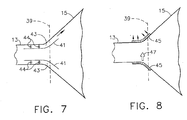
chamber 15 may be steered or directed towards one or more of theoutlet passages 17. The steering preferably occurs generally at a control plane 39 (Fig. 1) located where the flow leaves theinlet 13 and enters thechamber 15, although other locations in the chamber do not depart from the scope of this invention. After steering is accomplished, the jet will generally continue along a constant trajectory throughout thechamber 15. For instance, if air is needed in theupper annulus sector 29, air flow entering thechamber 15 is steered toward that sector to deliver air to that outlet passage and corresponding site of thenozzle 31. - Steering accomplished by a fluidic method, free from mechanical flow deflectors. In the preferred embodiment shown in Fig. 7,
several tabs 41 or plates are mounted about a periphery of theinlet 13 and entrance tochamber 15, generally at thecontrol plane 39. Thetabs 41 are generally parallel to the walls, forming achannel 43 or series of channels between each tab and the wall. Pressurized air, known as steering air, is introduced in thechannel 43 byconventional flow injectors 44 so it flows from the channel at a high velocity. The steering air can be introduced along any selected circumferential portion of the periphery of the inlet. The steering air preferably originates from the compressor discharge of theengine 19, although other sources are envisioned. The volume of steering air introduced into thechannel 43 is significantly less than the volume flowing through theinlet 13. Although a system of ducts and actuated valves (not shown) are required to distribute the steering air to selectedinjectors 44 about the circumference, the weight and complexity of this system are small because of the small amount of steering air needed. - Flow through the
inlet 13 is steered by injecting steering air at selected circumferential locations about the periphery of the inlet. The inlet flow is turned partially by a mechanism known to those skilled in the art as Coanda Effect turning. The Coanda Effect is a natural tendency of fluids to adhere to and be deflected by a surface nearly tangential to the flow path. The steering air from thechannel 43 flows generally parallel to a wall of thechamber 15 at a high velocity, producing a low static pressure which draws the jet traveling out of theinlet 13 toward the wall of the chamber. Steering air mixes with the jet and turns inlet flow parallel to the direction of motion of the steering flow. For example, in order to steer the jet upwardly, steering air is introduced into achannel 43 along an upper portion of the circumference of theinlet 13. Alternatively, to steer the jet downwardly, steering air is introduced into achannel 43 along a lower portion of the circumference of theinlet 13. Thus, the jet can be directed to adhere to one wall of thechamber 15, such as an extreme upper or left side surface. It is expected that by proper distribution of the steering air among thechannels 43 about the circumference of theinlet 13, the jet can be selectively directed to any angle between the walls, anywhere within the interior of thechamber 15, with reasonable degree of accuracy. - A second embodiment of the present invention, shown in Fig. 8, also steers the flow fluidically. It includes a
porous surface 45 or porous wall about the periphery of theinlet 13 and entrance to thechamber 15, generally at thecontrol plane 39. A vacuum or suction is applied through theporous surface 45 to draw the inlet air flow generally laterally to a selected trajectory. If necessary to improve the controllability of steering, a stream of steering air may be injected, indicated byarrow 47, to further push the flow. The injectedstream 47 is generally diametrically opposite to the applied suction and generally perpendicular to the inlet air flow. A combination of suction and opposite injection may be applied, or either suction or injection may be applied separately. It is expected that application of suction and/or opposed injection at suitable strengths and locations can steer the jet to any angle within the interior of thechamber 15 with a reasonable degree of accuracy. - In operation, the
control system 11 permits selective distribution of pressurized air along the inner surface of theexhaust nozzle 31. As the aircraft flight conditions vary and the engine is operated at several power settings, thenozzle 31 must achieve various throat areas. Thecontrol valve 21 in theinlet 13 is adjusted to vary the amount of flow that is fluidically injected to block the physical flow area. The jet is steered in thechamber 15 tooutlet passages 17 leading to sites at thethroat 35 of the nozzle, with the flow being symmetrically distributed about the throat. When thrust vectoring is needed in a maneuver or to augment control of the aircraft, the flow is steered to a new combination ofoutlet passages 17 within the chamber. Those outlet passages distribute the flow to sites that are not symmetric about thenozzle 31, thereby changing the direction of the exhaust stream. The jet in thechamber 15 may be steered to go entirely to one site in thenozzle 31, or it may be split among two or more sites in desired proportions. Steering is accomplished by one of several methods, preferably by changing the distribution of the small quantity of steering air. - Importantly, the fluidic control embodiments of the present invention achieve control of a fluidic exhaust nozzle using a fluidic device. The system functions like a double flow amplifier. The small quantity of steering air flow controls a greater quantity of inlet air flow, which in turn controls an even greater quantity of the main exhaust flow.
- Thus, the invention provides a control system for selectively adjusting effective flow areas of an aircraft engine exhaust nozzle to change operational characteristics of the nozzle. The
adjustable inlet 13 andchamber 15 result in lower weight, fewer parts, and reduced cost relative to fluidic nozzles of the prior art. The parts of the present invention, most of which are at thechamber 15, are readily packaged into one location in the aircraft to facilitate reduced vulnerability. - When introducing elements of the present invention or the preferred embodiment(s) thereof, the articles "a", "an", "the" and "said" are intended to mean that there are one or more of the elements. The terms "comprising", "including" and "having" are intended to be inclusive and mean that there may be additional elements other than the listed elements.
Claims (7)
- A control system (11) for selectively adjusting effective flow areas of an aircraft engine exhaust nozzle (31) to change operational characteristics of the nozzle (31), wherein the control system (11) comprises:a chamber (15) having a hollow interior, an upstream end, wand a downstream end;a plurality of outlet passages (17) at said downstream end and extending from the hollow interior of the chamber (15) to sites within the exhaust nozzle (31); andan adjustable inlet (13) extending from a pressurized air source (19) to the hollow interior of the chamber (15) at said upstream end for delivering a jet of pressurized air to the chamber (15), wherein the inlet (13) is adjustable to steer said jet of pressurized air to selected one or more outlet passages of said plurality of outlet passages at said downstream end of the chamber for the delivery of air via said one or more outlets to corresponding one or more sites within the exhaust nozzle (31) thereby to change the operational characteristics of the nozzle (31), characterised in thatthe adjustable inlet (13) is fluidically controlled, free from mechanical flow deflectors.
- A control system (11) as set forth in claim 1 wherein the inlet (13) is adjustable to vary the number of outlet passages (17) that receive pressurized air.
- A control system (11) as set forth in claim 1 wherein the inlet (13) is adjustable to vary a rate of flow through the inlet (13).
- A control system (11) as set forth in claim 1 wherein the inlet (13) is adjustable to vary a direction of flow through the nozzle (31) thereby to vary an angular orientation of thrust force produced by the nozzle (31).
- A control system (11) as set forth in claim 1 wherein said chamber (15) is oversized for said pressurized air delivered from the inlet (13) so that said air does not expand sufficiently to fill the chamber (15) as it flows through the chamber (15), said air separating from at least one peripheral wall of said chamber (15).
- A gas turbine engine for providing propulsion to an aircraft, wherein the engine has a fluidic control system (11) and comprises:a nozzle (31) having a duct for exhausting gas from the engine, said duct having at least one variable flow area for controlling operational characteristics of the engine;a source (19) of pressurized air; anda fluidic control system (11) for selectively adjusting said at least one flow area of the duct, the control system (11) being as set forth in claim 1.
- A method of controlling an aircraft engine exhaust nozzle (31) characterized in that the nozzle is of the type having fluidic injection capability whereby a first flow of pressurized gas is delivered to the nozzle (31) and injected into an exhaust stream for fluidically varying operational characteristics of the nozzle (31), the method comprising the step of selectively controlling said injection of the first flow into the exhaust stream using a fluidic control system (11) by injecting a second flow of pressurized gas into the first flow to adjust a distribution of the first flow delivered to the nozzle, so the exhaust stream is controlled fluidically through injection of the first flow and the first flow is controlled fluidically through injection of the second flow.
Applications Claiming Priority (2)
| Application Number | Priority Date | Filing Date | Title |
|---|---|---|---|
| US09/579,818 US6336319B1 (en) | 2000-05-26 | 2000-05-26 | Fluidic nozzle control system |
| US579818 | 2000-05-26 |
Publications (3)
| Publication Number | Publication Date |
|---|---|
| EP1158156A2 EP1158156A2 (en) | 2001-11-28 |
| EP1158156A3 EP1158156A3 (en) | 2003-10-29 |
| EP1158156B1 true EP1158156B1 (en) | 2007-04-11 |
Family
ID=24318471
Family Applications (1)
| Application Number | Title | Priority Date | Filing Date |
|---|---|---|---|
| EP01304570A Expired - Lifetime EP1158156B1 (en) | 2000-05-26 | 2001-05-24 | Fluidic nozzle control system |
Country Status (5)
| Country | Link |
|---|---|
| US (1) | US6336319B1 (en) |
| EP (1) | EP1158156B1 (en) |
| JP (2) | JP2002098002A (en) |
| DE (1) | DE60127756T2 (en) |
| ES (1) | ES2284593T3 (en) |
Families Citing this family (43)
| Publication number | Priority date | Publication date | Assignee | Title |
|---|---|---|---|---|
| US7159383B2 (en) * | 2000-10-02 | 2007-01-09 | Rohr, Inc. | Apparatus, method and system for gas turbine engine noise reduction |
| US6758032B2 (en) * | 2002-02-07 | 2004-07-06 | Lockheed Martin Corporation | System of pulsed detonation injection for fluid flow control of inlets, nozzles, and lift fans |
| US7296411B2 (en) * | 2002-06-21 | 2007-11-20 | Darko Segota | Method and system for regulating internal fluid flow within an enclosed or semi-enclosed environment |
| US6655632B1 (en) | 2002-08-27 | 2003-12-02 | General Electric Company | System and method for actively changing an effective flow-through area of an inlet region of an aircraft engine |
| WO2004061286A1 (en) * | 2002-12-18 | 2004-07-22 | Lockheed Martin Corporation | Apparatus and method for controlling primary fluid flow using secondary fluid flow injection |
| US7308966B2 (en) * | 2003-12-30 | 2007-12-18 | General Electric Company | Device for reducing jet engine exhaust noise using oscillating jets |
| US7412832B2 (en) * | 2004-03-26 | 2008-08-19 | General Electric Company | Method and apparatus for operating gas turbine engines |
| US7481038B2 (en) * | 2004-10-28 | 2009-01-27 | United Technologies Corporation | Yaw vectoring for exhaust nozzle |
| SE527829C2 (en) * | 2004-11-05 | 2006-06-13 | Volvo Aero Corp | Outlet nozzle for a jet engine and method for controlling a gas flow from the jet engine |
| EP1696116B1 (en) | 2005-02-24 | 2018-04-11 | Rolls-Royce plc | Thrust vectoring using fluid jets |
| US7424805B2 (en) * | 2005-04-29 | 2008-09-16 | General Electric Company | Supersonic missile turbojet engine |
| US7448199B2 (en) * | 2005-04-29 | 2008-11-11 | General Electric Company | Self powdered missile turbojet |
| US7475545B2 (en) * | 2005-04-29 | 2009-01-13 | General Electric Company | Fladed supersonic missile turbojet |
| US7509797B2 (en) * | 2005-04-29 | 2009-03-31 | General Electric Company | Thrust vectoring missile turbojet |
| FR2887929B1 (en) | 2005-06-30 | 2010-12-03 | Soc Nat Detude Et De Construction De Moteurs Daviation Snecma | TUYERE WITH PUSH ORIENTATION |
| DE102006013595B4 (en) * | 2006-03-22 | 2016-03-31 | Danger Möricke | Turbojet afterburner and associated control systems |
| US7793504B2 (en) * | 2006-05-04 | 2010-09-14 | Rolls-Royce Corporation | Nozzle with an adjustable throat |
| FR2904663B1 (en) * | 2006-08-01 | 2012-02-03 | Snecma | DOUBLE FLOW TURBOMACHINE WITH ARTIFICIAL VARIATION OF ITS COLLEGE SECTION |
| US8015819B2 (en) * | 2006-09-29 | 2011-09-13 | The United States Of America As Represented By The Administrator Of The National Aeronautics And Space Administration | Wet active chevron nozzle for controllable jet noise reduction |
| US7775460B2 (en) | 2006-10-24 | 2010-08-17 | United Technologies Corporation | Combustion nozzle fluidic injection assembly |
| US8096104B2 (en) * | 2007-05-31 | 2012-01-17 | United Technologies Corporation | Fluidic vectoring for exhaust nozzle |
| BRPI0914608A2 (en) * | 2008-07-04 | 2015-12-08 | Bae Systems Plc | thrust vectorization apparatus, jet engine, and method for upgrading a jet engine. |
| EP2163754A1 (en) * | 2008-09-16 | 2010-03-17 | BAE Systems PLC | Thrust vectoring apparatus for a jet engine, corresponding jet engine, thrust vectoring method and upgrading method for a jet engine |
| US8800259B2 (en) * | 2008-09-22 | 2014-08-12 | Rolls-Royce North American Technologies, Inc. | Thrust vector system |
| US8371104B2 (en) * | 2008-10-10 | 2013-02-12 | Lockheed Martin Corporation | System and apparatus for vectoring nozzle exhaust plume from a nozzle |
| US9551296B2 (en) | 2010-03-18 | 2017-01-24 | The Boeing Company | Method and apparatus for nozzle thrust vectoring |
| US8316631B2 (en) * | 2010-09-30 | 2012-11-27 | Lockheed Martin Corporation | Exhaust plume heat effect reducing method and apparatus |
| US10060389B2 (en) | 2010-12-14 | 2018-08-28 | The Boeing Company | Method and apparatus for variable exhaust nozzle exit area |
| US20120145808A1 (en) * | 2010-12-14 | 2012-06-14 | The Boeing Company | Method and apparatus for variable exhaust nozzle exit area |
| US20130305731A1 (en) * | 2012-05-17 | 2013-11-21 | Philip John MORRIS | Methods and apparatus for providing fluidic inserts into an exhaust stream to reduce jet noise from a nozzle |
| CN103644043A (en) * | 2012-12-22 | 2014-03-19 | 摩尔动力(北京)技术股份有限公司 | Mass gain type spray pipe |
| CN203441604U (en) * | 2013-02-15 | 2014-02-19 | 通用电气公司 | System for reducing backpressure in gas turbine system |
| CN103899433A (en) * | 2014-03-31 | 2014-07-02 | 西北工业大学 | Novel thrust vectoring nozzle structure adopting shock vectoring controlling |
| US10563613B2 (en) | 2015-08-31 | 2020-02-18 | Rolls-Royce North American Technologies Inc. | Coanda device for a round exhaust nozzle |
| US10464668B2 (en) | 2015-09-02 | 2019-11-05 | Jetoptera, Inc. | Configuration for vertical take-off and landing system for aerial vehicles |
| KR20180061182A (en) | 2015-09-02 | 2018-06-07 | 제톱테라 잉크. | Ejector and airfoil structure |
| US11001378B2 (en) | 2016-08-08 | 2021-05-11 | Jetoptera, Inc. | Configuration for vertical take-off and landing system for aerial vehicles |
| USD868627S1 (en) | 2018-04-27 | 2019-12-03 | Jetoptera, Inc. | Flying car |
| WO2017218841A1 (en) | 2016-06-15 | 2017-12-21 | The Regents Of The University Of California | Two-dimensional supersonic nozzle thrust vectoring using staggered ramps |
| US10739002B2 (en) | 2016-12-19 | 2020-08-11 | General Electric Company | Fluidic nozzle assembly for a turbine engine |
| EP3645854A4 (en) | 2017-06-27 | 2021-03-24 | Jetoptera, Inc. | Configuration for vertical take-off and landing system for aerial vehicles |
| US10807703B2 (en) * | 2018-07-19 | 2020-10-20 | General Electric Company | Control system for an aircraft |
| CN117227987B (en) * | 2023-11-14 | 2024-03-12 | 中国空气动力研究与发展中心计算空气动力研究所 | Unilateral expansion tail spray groove integrally designed with control surface |
Family Cites Families (25)
| Publication number | Priority date | Publication date | Assignee | Title |
|---|---|---|---|---|
| CA618830A (en) | 1961-04-25 | Societe Nationale D'etude Et De Construction De Moteurs D'aviation | Device for varying the effective area of a jet propulsion nozzle | |
| US2699906A (en) | 1949-10-25 | 1955-01-18 | Northrop Aircraft Inc | Air inlet for airplane gaseous combustion turbine engines |
| DE1043723B (en) * | 1952-05-21 | 1958-11-13 | Snecma | Method and device for influencing the cross section and / or the direction of the gas flow core passing through the jet pipe of a recoil drive |
| FR1117244A (en) | 1954-12-20 | 1956-05-18 | Snecma | Supersonic wind tunnel with variable number of machines |
| FR1182810A (en) | 1957-09-16 | 1959-06-30 | Snecma | Improvements to adjustable section ejection nozzles |
| DE1240747C2 (en) * | 1962-02-08 | 1975-07-10 | Societe Bertin & Cie., Paris | JET THROTTLE FOR HOT GASES WITH JET DEFLECTION DUE TO THE INTRODUCTION OF AN AUXILIARY FLUID |
| FR1332003A (en) * | 1962-02-12 | 1963-12-16 | ||
| FR1351404A (en) * | 1962-08-07 | 1964-02-07 | Snecma | Aerodynamic or hydrodynamic servo-valve which can be used in particular for the steering and stabilization of rockets |
| US3204405A (en) * | 1964-02-20 | 1965-09-07 | Raymond W Warren | Three dimensional jet vectoring system |
| US3289410A (en) | 1964-06-17 | 1966-12-06 | William W Balwanz | Method and apparatus for weeding the flame plasma of a rocket exhaust |
| GB1019203A (en) | 1964-06-18 | 1966-02-02 | Rolls Royce | Jet nozzle |
| US3325103A (en) | 1964-08-05 | 1967-06-13 | Aerospace Corp | Thrust vector control for reaction engines |
| US3425431A (en) * | 1965-03-29 | 1969-02-04 | American Standard Inc | Control apparatus and methods |
| FR1456926A (en) * | 1965-09-17 | 1966-07-08 | Bertin & Cie | Improvements made to fluid deflection devices and their application at dilution |
| US3370794A (en) | 1965-11-08 | 1968-02-27 | Navy Usa | Annular plenum nozzle for controlling trajectory of rockets |
| US3374954A (en) * | 1966-03-03 | 1968-03-26 | Thiokol Chemical Corp | Nozzle cooling and thrust vector control apparatus |
| US3420060A (en) * | 1966-04-22 | 1969-01-07 | Mc Donnell Douglas Corp | Pressure induced jet vectoring augmentation apparatus |
| US3421324A (en) * | 1966-05-03 | 1969-01-14 | Philco Ford Corp | Fluid flow control apparatus |
| US3698642A (en) * | 1966-11-04 | 1972-10-17 | Thiokol Chemical Corp | Thrust vector control system |
| US3740003A (en) * | 1972-03-13 | 1973-06-19 | Us Army | Secondary injection/jet reaction control |
| US4077572A (en) * | 1976-03-25 | 1978-03-07 | Chandler Evans Inc. | Reduced size altitude insensitive thrust vector control nozzle |
| JPS59728B2 (en) * | 1976-08-10 | 1984-01-09 | 晴海 浅尾 | Fluid flow direction control device using sub-jet |
| US5664415A (en) | 1994-06-01 | 1997-09-09 | Lockheed Fort Worth Company | After-burning turbo-fan engine with a fixed geometry exhaust nozzle having a variable flow coefficient |
| US6112513A (en) * | 1997-08-05 | 2000-09-05 | Lockheed Martin Corporation | Method and apparatus of asymmetric injection at the subsonic portion of a nozzle flow |
| US5996936A (en) * | 1997-09-29 | 1999-12-07 | General Electric Company | Fluidic throat exhaust nozzle |
-
2000
- 2000-05-26 US US09/579,818 patent/US6336319B1/en not_active Expired - Lifetime
-
2001
- 2001-05-24 ES ES01304570T patent/ES2284593T3/en not_active Expired - Lifetime
- 2001-05-24 DE DE60127756T patent/DE60127756T2/en not_active Expired - Lifetime
- 2001-05-24 EP EP01304570A patent/EP1158156B1/en not_active Expired - Lifetime
- 2001-05-25 JP JP2001156216A patent/JP2002098002A/en active Pending
-
2011
- 2011-10-07 JP JP2011223002A patent/JP2012052548A/en active Pending
Also Published As
| Publication number | Publication date |
|---|---|
| ES2284593T3 (en) | 2007-11-16 |
| DE60127756D1 (en) | 2007-05-24 |
| EP1158156A3 (en) | 2003-10-29 |
| JP2002098002A (en) | 2002-04-05 |
| US6336319B1 (en) | 2002-01-08 |
| JP2012052548A (en) | 2012-03-15 |
| EP1158156A2 (en) | 2001-11-28 |
| DE60127756T2 (en) | 2007-12-27 |
Similar Documents
| Publication | Publication Date | Title |
|---|---|---|
| EP1158156B1 (en) | Fluidic nozzle control system | |
| US6679048B1 (en) | Apparatus and method for controlling primary fluid flow using secondary fluid flow injection | |
| US6634595B2 (en) | Method and apparatus for controlling aircraft inlet air flow | |
| JP5265519B2 (en) | Inlet distortion and recovery control system | |
| US5706650A (en) | Vectoring nozzle using injected high pressure air | |
| US2812636A (en) | Process and device for deflecting jets | |
| US8371104B2 (en) | System and apparatus for vectoring nozzle exhaust plume from a nozzle | |
| US8800259B2 (en) | Thrust vector system | |
| US20060150612A1 (en) | Thrust vector control | |
| US20070256419A1 (en) | Nozzle with an adjustable throat | |
| US7681400B2 (en) | Exhaust assembly forming a horizontal propulsion gas elbow in an aircraft | |
| US5833139A (en) | Single variable flap exhaust nozzle | |
| CN111470032B (en) | Pneumatic composite control tailless flying wing layout unmanned aerial vehicle and control method thereof | |
| JP2000356167A (en) | Dolphin cascade vane | |
| CN104847529A (en) | Three-degree of freedom vectored thrust system based on novel air-operated vectoring thrust nozzle | |
| US6298658B1 (en) | Multi-stable thrust vectoring nozzle | |
| RU2425241C2 (en) | Jet nozzle with thrust orientation, its operating method, jet turbine engine and unpiloted aircraft equipped with such nozzle | |
| EP3088720B1 (en) | Nozzle for jet engines | |
| US10781756B2 (en) | Active tip clearance control system for gas turbine engine | |
| US4519562A (en) | Aircraft | |
| JP2007170397A (en) | Propulsion system for producing thrust and nozzle for forming fluid throat | |
| EP1585896B1 (en) | Apparatus and method for controlling primary fluid flow using secondary fluid flow injection | |
| US5431344A (en) | Sliding throat gas turbine engine nozzle | |
| RU2663440C1 (en) | Unboosted turbojet engine | |
| EP1696116B1 (en) | Thrust vectoring using fluid jets |
Legal Events
| Date | Code | Title | Description |
|---|---|---|---|
| PUAI | Public reference made under article 153(3) epc to a published international application that has entered the european phase |
Free format text: ORIGINAL CODE: 0009012 |
|
| AK | Designated contracting states |
Kind code of ref document: A2 Designated state(s): AT BE CH CY DE DK ES FI FR GB GR IE IT LI LU MC NL PT SE TR |
|
| AX | Request for extension of the european patent |
Free format text: AL;LT;LV;MK;RO;SI |
|
| PUAL | Search report despatched |
Free format text: ORIGINAL CODE: 0009013 |
|
| AK | Designated contracting states |
Kind code of ref document: A3 Designated state(s): AT BE CH CY DE DK ES FI FR GB GR IE IT LI LU MC NL PT SE TR |
|
| AX | Request for extension of the european patent |
Extension state: AL LT LV MK RO SI |
|
| 17P | Request for examination filed |
Effective date: 20040429 |
|
| AKX | Designation fees paid |
Designated state(s): DE ES FR GB IT SE |
|
| 17Q | First examination report despatched |
Effective date: 20040708 |
|
| GRAP | Despatch of communication of intention to grant a patent |
Free format text: ORIGINAL CODE: EPIDOSNIGR1 |
|
| GRAS | Grant fee paid |
Free format text: ORIGINAL CODE: EPIDOSNIGR3 |
|
| GRAA | (expected) grant |
Free format text: ORIGINAL CODE: 0009210 |
|
| AK | Designated contracting states |
Kind code of ref document: B1 Designated state(s): DE ES FR GB IT SE |
|
| REG | Reference to a national code |
Ref country code: GB Ref legal event code: FG4D |
|
| REF | Corresponds to: |
Ref document number: 60127756 Country of ref document: DE Date of ref document: 20070524 Kind code of ref document: P |
|
| REG | Reference to a national code |
Ref country code: SE Ref legal event code: TRGR |
|
| REG | Reference to a national code |
Ref country code: ES Ref legal event code: FG2A Ref document number: 2284593 Country of ref document: ES Kind code of ref document: T3 |
|
| PLBE | No opposition filed within time limit |
Free format text: ORIGINAL CODE: 0009261 |
|
| STAA | Information on the status of an ep patent application or granted ep patent |
Free format text: STATUS: NO OPPOSITION FILED WITHIN TIME LIMIT |
|
| 26N | No opposition filed |
Effective date: 20080114 |
|
| REG | Reference to a national code |
Ref country code: FR Ref legal event code: PLFP Year of fee payment: 16 |
|
| PGFP | Annual fee paid to national office [announced via postgrant information from national office to epo] |
Ref country code: ES Payment date: 20160526 Year of fee payment: 16 Ref country code: DE Payment date: 20160527 Year of fee payment: 16 Ref country code: GB Payment date: 20160527 Year of fee payment: 16 |
|
| PGFP | Annual fee paid to national office [announced via postgrant information from national office to epo] |
Ref country code: IT Payment date: 20160520 Year of fee payment: 16 Ref country code: SE Payment date: 20160527 Year of fee payment: 16 Ref country code: FR Payment date: 20160530 Year of fee payment: 16 |
|
| REG | Reference to a national code |
Ref country code: DE Ref legal event code: R119 Ref document number: 60127756 Country of ref document: DE |
|
| REG | Reference to a national code |
Ref country code: SE Ref legal event code: EUG |
|
| GBPC | Gb: european patent ceased through non-payment of renewal fee |
Effective date: 20170524 |
|
| PG25 | Lapsed in a contracting state [announced via postgrant information from national office to epo] |
Ref country code: SE Free format text: LAPSE BECAUSE OF NON-PAYMENT OF DUE FEES Effective date: 20170525 |
|
| REG | Reference to a national code |
Ref country code: FR Ref legal event code: ST Effective date: 20180131 |
|
| PG25 | Lapsed in a contracting state [announced via postgrant information from national office to epo] |
Ref country code: DE Free format text: LAPSE BECAUSE OF NON-PAYMENT OF DUE FEES Effective date: 20171201 Ref country code: GB Free format text: LAPSE BECAUSE OF NON-PAYMENT OF DUE FEES Effective date: 20170524 |
|
| PG25 | Lapsed in a contracting state [announced via postgrant information from national office to epo] |
Ref country code: FR Free format text: LAPSE BECAUSE OF NON-PAYMENT OF DUE FEES Effective date: 20170531 Ref country code: IT Free format text: LAPSE BECAUSE OF NON-PAYMENT OF DUE FEES Effective date: 20170524 |
|
| REG | Reference to a national code |
Ref country code: ES Ref legal event code: FD2A Effective date: 20180703 |
|
| PG25 | Lapsed in a contracting state [announced via postgrant information from national office to epo] |
Ref country code: ES Free format text: LAPSE BECAUSE OF NON-PAYMENT OF DUE FEES Effective date: 20170525 |