The present invention relates generally to the molding of optical
glass lenses and, more particularly, to methods for producing glass molds from
yttria aluminosilicate glasses for molding optical glass elements therewith.
Various methods and apparatus for the compression molding of
glass optical elements are known in the prior art. With these methods and
apparatus, optical element preforms sometimes referred to as gobs are
compression molded at high temperatures to form glass lens elements. The basic
process and apparatus for molding glass elements is taught in a series of patents
assigned to Eastman Kodak Company. Such patents are U.S. Patent No.
3,833,347 to Engle et al., U.S. Patent No. 4,139,677 to Blair et al., and U.S. Patent
No. 4,168,961 to Blair. These patents disclose a variety of suitable materials for
construction of mold inserts used to form the optical surfaces in the molded
optical glass elements. Those suitable materials for the construction of the mold
inserts included glasslike or vitreous carbon, silicon carbide, silicon nitride, and a
mixture of silicon carbide and carbon. In the practice of the process described in
such patents, a glass preform or gob is inserted into a mold cavity with the mold
being formed out of one of the above mentioned materials. The molds reside
within a chamber in which is maintained a non-oxidizing atmosphere during the
molding process. The preform is then heat softened by increasing the temperature
of the mold to thereby bring the preform up to a viscosity ranging from 107-109
poise for the particular type of glass from which the preform has been made.
Pressure is then applied to force the preform to conform to the shape of the mold
cavity. The mold and preform are then allowed to cool below the glass transition
temperature of the glass. The pressure on the mold is then relieved and the
temperature is lowered further so that the finished molded lens can be removed
from the mold.
U.S. Patent Nos. 4,897,101 and 4,964,903, both to Carpenter et al.,
teach a method and apparatus for molding optical glass elements using molded
glass molds. According to such method and apparatus, a metal master mold is
first manufactured. Suitable materials for forming such master are Inconel 718,
stainless steel type 420, tungsten carbide, and the like. The master surfaces may
be coated or plated to minimize degradation of the molding surface through
chemical attack, corrosion, denting, abrasion or adherence of the material being
molded. Lens design data is apparently used to calculate the profile of the surface
of the master. It is stated that the profile compensates for the different coefficient
of thermal expansion of the lens and mold materials at the forming temperature to
generate the required mold figure. Because Carpenter et al. teaches the use of
metal master tooling, the process and method taught thereby is temperature
limited. The glass molds formed with the metal tools must be made from glass
having a relatively low molding temperatures (less than about 500 °C). As a
result, lenses molded using such glass molds must have a molding temperature
that is even lower than that of the glass mold. The glass is taught as being
acceptable for use with such glass molds had Tg no greater than 402 °C. Thus, the
commercial viability of such method and apparatus of Carpenter et al. is, at best,
questionable given the limited types of glass which may be used to mold glass
optical elements using such method and apparatus. Indeed, there are very few
commercially available glasses which can be used in the practice of such method
and apparatus. As a result, apparently Carpenter et al found it necessary to
develop new optical glass compositions that could be used with their method and
apparatus. To date, only one commercially available optical glass, Corning
C0550, meets the above requirements.
The use of glass molds has many benefits. Because the glass
molds are replicated from a master mold of the inverse shape, the glass molds
produced from the master will inherently have less dimensional variability. Glass
molds are also more cost effective compared with diamond turned molds or
ground and polished molds such as silicon carbide. A population of molds for
multiple cavity manufacturing may be fabricated very quickly from glass molds
compared with single-point turned molds or traditional ground and polished hard
materials such as silicon carbide.
It is therefore an object of the present invention to provide a
method for forming glass molding tools using an amorphous base material from
which a working mold can be formed, wherein the working mold can be used to
mold optical glass elements from glasses having a molding temperature in the
range of from 400°C to 825°C.
Another object of the present invention is to provide a method for
forming glass molding tools from an amorphous material having a short or fragile
viscosity curve characteristic.
It is a further object of the present invention to provide a method
for making molded glass tools for use in molding optical glass elements wherein
the base material used to mold the glass tool has a coefficient of thermal
expansion in the range of from 25 x 10-7/°C to 70 x 10-7/°C.
Yet another object of the present invention is to provide a method
for making molded glass tools for use in molding optical glass elements wherein
the coefficient of thermal expansion of the material of the mold tool preform may
be altered from 25 x 10-7/°C to 70 x 10-7/°C without significantly altering the glass
transition temperature or temperature for at which the glass material has a
viscosity of at least 1015 poise.
Briefly stated, these and numerous other features, objects and
advantages of the present invention will become readily apparent upon a reading
of the detailed description, claims and drawings set forth herein. These features,
objects and advantages are accomplished by first making a master molding tool
from a material having a maximum use temperature in the range of from 900°C to
2500°C. The preferred material for this purpose is silicon carbide, produced by
chemical vapor deposition. Other materials which can be used to fabricate the
master mold tool include Vycor®, fused silica, fused quartz, and various oxide,
nitride, carbide, silicide, and boride ceramics and composites thereof. The master
tool is produced on computer-controlled grinding and polishing equipment to a
very high degree of accuracy (peak to valley of 0.015 µm). This master tool is, in
turn, used in a glass molding process to produce working tools of opposite
curvature. The working tools are then used to fabricate the finished optical glass
lenses in a production mode. The method includes the calibration of curves and
for a two-step molding process where the three materials (master tool, working
tool, and lens) have different coefficients of thermal expansion and are used at
two different temperatures (tool process and lens process). This is particularly
important for aspheric surfaces. The system requires the identification of a
hierarchy of glasses such that the working tool glass has a strain point above the
process temperature for the lens glass. If the strain point of the working tool is
not greater than the process temperature of the lens glass, curve creep will result
as the working tool deforms a little with each molding cycle. An appropriate
release agent is also required.
As stated above, once the master tool has been created, it is used to
mold the working tool. Since the lenses ultimately to be molded through the use
of the working tool have a molding temperature in the range of from 400°C to
825°C, the working tool should have a Tg or strain point that is at least 50°C
greater than the molding temperature of the glass lenses. An amorphous-based
oxide glass containing yttria, alumina, and silica is formulated to have a
predetermined CTE. Such glass, called yttria aluminosilicate (YAS) glass, is very
refractory with Tg's ranging from 880°C to 910°C. It has been surprisingly found
that yttria aluminosilicate glasses have very short viscosity characteristics which
allow for the fabrication of bubble-free melts for high-quality cast slabs.
Furthermore, the composition of yttria aluminosilicate glasses may be adjusted to
yield glasses with coefficients of thermal expansion that range from 25 x 10-7/°C
to 70 x 10-7/°C without significantly altering the glass transition temperature of
the glass. The term "significantly" as used herein with regard to altering glass
transition temperature is intended to mean not more than ±25°C. Preferably, the
composition of yttria aluminosilicate glasses may be adjusted to yield glasses with
coefficients of thermal expansion that range from 25 x 10-7/°C to 70 x 10-7/°C with
only a ±10°C variation in Tg. Further, such YAS glass has a viscosity of less than
102 poise at a temperature of less than 200°C. A preform made of the YAS glass
is molded to yield a working mold tool therefrom. This results in a working mold
tool that includes a molded optical element forming surface, and that has a
viscosity of at least 1015 poise at the molding temperature the glass optics to be
molded therewith. The YAS working mold tool is then used to mold glass optical
elements such as lenses with the molded optical element forming surface. The
CTE and geometry of the glass optical elements are used to determine a desired
range for the predetermined CTE of the YAS glass. Other rare earth glasses may
potentially be used in the practice of method of the present invention in place of
yttria aluminosilicate glasses.
Preferably, the composition of rare earth and yttria aluminosilicate
glasses may be adjusted to yield glasses with coefficients of thermal expansion
that range from 25 x 10-7/°C to 70 x 10-7/°C also without significantly altering the
temperature at which the rare earth and yttria aluminosilicate glasses have a
viscosity of at least 1015. Again, the term "significantly" as used herein with
regard to altering the temperature at which the rare earth and yttria aluminosilicate
glasses have a viscosity of at least 015 is intended to mean not more than ±25°C.
A first surface figure for the optical element to be molded with the
working tool is defined. A second surface figure is computed for the master tool.
A third surface figure for the working tool is then calculated based upon the first
surface figure and the coefficient of thermal expansion of the optical element, the
master tool, and the working tool, as well as the temperature at which the working
tool is molded and the temperature at which the optical element or lens is to be
molded. The master tool is ground and polished to achieve the second surface
figure. A release coating is applied to the master tool and the master tool is used
to mold the working tool.
Figure 1 is a cross-sectional schematic of a mold assembly for use
in the practice of the present invention.
Figure 2 is a cross-sectional view of the mold super ring.
Figure 3 is a top plan view of the mold super ring.
Figure 4 is a side elevation/partial section view of a glass working
mold tool.
Figure 5 is a cross-sectional schematic of an alternative
embodiment mold assembly for use in the practice of the present invention with
the master mold tool removed therefrom.
Figure 6 is a cross-sectional schematic of the alternative
embodiment mold assembly of Figure 5 with the master mold tool inserted therein
but not shown in section.
Figure 7 is a cross-sectional schematic of an alternative
embodiment mold assembly of Figure 5 with the master mold tool and a glass
preform inserted therein (not in section) and with the upper mold housing lowered
to engage the master mold tool.
Figure 8 is a cross-sectional schematic of an alternative
embodiment mold assembly of Figure 5 with the master mold tool and a glass
preform inserted therein and with the upper mold housing in a fully lowered
position.
Figure 9 is a graph comparing the viscosities as a function of
temperature for Corning 1723, Mo-Sci YAS-6, Sem-Com SCE-3+5% SiO2, and
Corning 7810.
Figure 10 is a graph showing the glass transition temperature of
various rare earth aluminosilicate glasses as a function of ionic radius.
Figure 11 is a graph showing the coefficient of thermal expansion
of yttria aluminosilicate glass as a function of yttria composition.
Figure 12 is a graph showing the glass transition temperature of
yttria aluminosilicate glass as a function of composition.
Figure 13 is a probability plot showing the life of a yttria
aluminosilicate (YAS-6) glass molds coated with either carbon or a silicon
carbide/carbon composite.
Figure 14 is a probability plot showing the life of alkali
aluminosilicate (SCE-3 + 5% SiO2) glass molds coated with silicon
carbide/carbon composite.
Turning first to Figure 1, there is shown a mold assembly 10 in
cross-section used to form the glass molding tools of the present invention. The
mold assembly 10 includes a lower mold housing 12 and an upper mold housing
14. At the base of lower mold housing 12 is a hearth plate 16. Supported on
hearth plate 16 within lower mold housing 12 is spacer sleeve 18. Also supported
on hearth plate 16 is mold super ring 20 which mounts within spacer sleeve 18.
Mold super ring 20 includes a cylindrical opening 22 therethrough having a
cylindrical axis which is substantially collinear with the cylindrical axis of mold
super ring 20. Mold super ring 20 further includes an upper and a lower counter
bore which have cylindrical axes which are collinear with the cylindrical axis of
cylindrical opening 22 thereby resulting in an upper annular shoulder 24 and a
lower annular shoulder 26. (See Fig. 2.) Supported within mold super ring 20 is
master mold tool 28. Master mold tool 28 includes an annular flange 30 which
projects radially to engage upper annular shoulder 24 thereby suspending master
mold tool 28 within mold super ring 20. At the lower end of master mold tool 28
is mold surface 32. In such manner, there is created a mold cavity 34 defined at
the lower end by hearth plate 16, peripherally by mold super ring 20, and at the
upper end thereof by mold surface 32.
Upper mold housing 14 includes a cylindrical member 36 aligned
with lower mold housing 12. Mounted to cylindrical member 36 is a pusher plate
38.
In operation, a glass preform is inserted within the mold cavity 34
and the master mold tool 28 is inserted into the mold super ring 20. Means not
shown are employed to drive upper mold housing 14 downward causing pusher
plate 38 to engage the upper surface of master mold tool 28. The glass preform
and mold have already been heated to above the Tg (glass transition temperature)
of the glass used to make the glass preform. In such manner, the glass preform is
forced to conform to the shape of the mold cavity 34.
It is not sufficient to achieve accurate surfaces in molding if the
surfaces of the molding element are not properly aligned to one another. This is
particularly true for aspheric surfaces where no realignment of the lens assembly
can remove the error completely. A mastering system for molding mold tools has
a more difficult task in this respect than direct molding of lens elements.
Nevertheless, with proper care and tolerancing of tools, very good results can be
achieved.
The spacer sleeve 18 is particular to a given master mold tool 28
and the glass mold tool to be generated therewith. In such manner, the spacer
sleeve 18 allows the same mold assembly 10 to be used to run different sized
mold super rings 20 and, thus, different sized master mold tools 28.
The material for hearth plate 16 is chosen for its conductive
heating characteristics while the material for the pusher plate 38 is chosen for its
mechanical strength. Many alternatives may be contemplated for these materials
but the preferred material for hearth plate 18 is carbon (for example, P-03 graphite
as manufactured by Pure Carbon Company of St. Mary's PA) and the preferred
material for pusher plate 38 is steel.
Release of the molded glass tool is also a consideration. The mold
super ring 20 is made of carbon (P-03 graphite) or Vycor® to exacting tolerances
at the cylindrical axis of cylindrical opening 22 should align with the cylindrical
axis of master mold tool 28 which, in turn, should align with the cylindrical axis
of the glass mold tool to be made within mold cavity 34. In use, the mold
assembly 10 is assembled as shown in Fig. 1 except that the glass preform is
placed in the bottom of mold super ring 20 on hearth plate 16. The master mold
tool 28 is then loaded into mold super ring 20 over the glass preform. The mold
assembly is heated and forced to close after achieving the appropriate
temperature. Figure 1 shows the mold assembly in an open position after pressing
has occurred. There are slots 35 (see Fig. 3) in the top of the mold super ring 20
that extend below the master mold tool flange 30 to allow for extraction of the
master mold tool 28 from the mold super ring 20. The master mold tool 28, the
glass mold tool 40 formed therewith, and the mold super ring 20 are removed
from mold assembly 10 after cooling. The master mold tool 28 is then extracted
and the glass mold tool 40 is pushed out the bottom of mold super ring 20 (if
necessary). The mold assembly 10 is then ready for use again.
Looking at Figure 4, there is shown in partial cross-section an
example of a glass working mold tool 40 made with the mold assembly 10
depicted in Fig. 1. The glass working mold tool 40 includes a mold surface 42
which may be aspherical. The glass working mold tool 40 further includes an
annular flange portion 44 extending radially therefrom.
Turning to Figures 5 through 8, there is shown an alternative
embodiment of the mold assembly depicted in Fig. 1. The mold assembly 100
includes a lower mold housing 112 and an upper mold housing 114. At the base
of lower mold housing 112 is a hearth plate 116. Supported on hearth plate 116
within lower mold housing 112 is spacer sleeve 118. Also supported on hearth
plate 116 is mold super ring 120 which mounts within spacer sleeve 118. Mold
super ring 120 includes a cylindrical opening 122 therethrough having a
cylindrical axis which is substantially collinear with the cylindrical axis of mold
super ring 120. Supported within mold super ring 120 is master mold tool 128
(see Figs. 6 through 8). Master mold tool 128 includes an annular flange 130
which projects radially to engage upper annular surface 124 of mold super ring
120 when master mold tool 128 is fully inserted into cylindrical opening 122. At
the lower end of mold tool 128 is mold surface 132. In such manner, there is
created a mold cavity 134 defined at the lower end by hearth plate 116,
peripherally by mold super ring 120, and at the upper end thereof by mold surface
132. Upper mold housing 114 includes a cylindrical member 136 aligned with
lower mold housing 112. Mounted to cylindrical member 136 is a pusher plate
138. This alternative mold assembly 100 differs from the mold assembly 10
chiefly in the configuration of the mold super ring 120 and in the configuration of
the hearth plate 116. By creating a recess 140 in hearth plate 116 to accommodate
the formation of a flange at the base of the working tool and by suspending master
mold tool 128 from the annular flange 130 extending therefrom, mold super ring
120 becomes a plain cylindrical shape with a single cylindrical opening 122
therethrough.
In operation, a generally cylindrical preform 150 is inserted into
cylindrical opening 122 to rest upon hearth plate 116. Master mold tool 128 is
then inserted into cylindrical opening 122 such that mold surface 132 rests on
preform 150 (see Fig. 7). After the mold assembly is heated to the predetermined
temperature, upper mold housing 114 is moved vertically downward such that
pusher plate 138 engages the top surface of the master mold tool 128. In such
manner, master mold tool 128 is driven downward into cylindrical opening 122
until annular flange 130 engages the upper annular surface 124 of mold super ring
120 resulting in preform 150 being forced to conform to the shape of mold cavity
134 (see Fig. 8). Preform 150 thus becomes a working mold tool 160 with an
annular flange 162 and a generally concave molding surface.
The method of the present invention employs the use of a
mastering system to produce glass molding tools which are ultimately used for
molding finished optical glass elements. The master mold tool 28 is produced on
a computer-controlled grinding apparatus to a very high degree of accuracy (peek
to valley of 0.15 µm). An example of an acceptable of a computer-controlled
grinding apparatus is the Ultra 2000 as manufactured by Rank Pneumo of Keene,
NH. The master mold tool 28 is then polished to reduce surface roughness as a
result of the grinding operation. Polishing may be performed with a polishing
machine such as is manufactured by Loh Optik Maschinen AG of Wetzlar,
Germany. The master mold tool 28, once fabricated, is, in turn, used in a glass
molding process in the same molding machines used to make the finished glass
optical elements. In such manner, the master mold tool 28 is used to produce a
glass mold tool 40 wherein the glass mold tool 40 has a mold surface 42 of
opposite curvature to the curvature of mold surface 32 of master mold tool 28.
Glass mold tools 40 are then used to fabricate the finished lenses in a production
mode.
The method includes the calibration of curves for the two-step
molding process where the master mold tool 28, the glass mold tool 40, and the
finished lens are made from three different materials having different coefficients
of thermal expansion. In addition, different working temperatures are involved.
The temperature at which the master mold tool 28 is used to form the glass mold
tool 40 is necessarily higher than the temperature at which the glass mold tool 40
is used to mold the finished lens. The calibration of curves is particularly
important for aspheric surfaces and the system of the present invention requires
the identification of a hierarchy of glasses such that the material of the glass mold
tool 40 has a strain point above the process temperature at which the finished
lenses are formed. If this is not the case, curve creep will be the result as the mold
surface 42 moves a little with each mold cycle. An appropriate release agent is
also required in the molding operations.
The calibration of curves (lens and mold surfaces) is based on
simple first order theory of expansion and the assumption that the materials
involved are isotropic. It requires the empirical data of the materials and
processes, namely, the coefficients of thermal expansion that apply for the
temperatures of the processes, and the design coefficients of the desired lens
curve(s).
First order expansion theory states that the fractional change in a
linear dimension of a body is directly proportional to its change in temperature.
This can be stated mathematically as:
▵LLo = α•▵T
where the constant of proportionality is called the linear coefficient of thermal
expansion (CTE) and is determined experimentally. ▵L is the change in length,
Lo is the original length, and ▵T is the change in temperature from process to
ambient. It has been empirically determined that for most optical glasses, the
process temperature minus 40°C is a good measure of this for a glass molding
process. Twenty of these degrees represent ambient (room temperature ~20°C)
and the other twenty degrees can be thought of as the decrement from the molding
temperature to the point where the glass has its structural integrity so to speak. In
other words, the glass at this point has a surface which is self-supporting
independent of the tool. α has units of reciprocal temperature. If ▵L = L - L0 then
Equation (1) can be cast in another form:
L = Lo(1+α·▵T)
where L is the length at final temperature. This applies to all linear dimensions of
isotropic materials where the behavior in the temperature regime can be described
by a constant CTE. Expansion behavior at intermediate temperatures need not be
considered. Only the expansion behavior at the temperature end points is of
concern. Therefore, an α which is not necessarily a handbook value can be
defined that satisfies Equation (2). Because radius is a linear dimension, it can be
described by Equation (3) thus:
RT = RL (1 + αG · ▵T)
where RT is the radius of the lens at the operating temperature of the process, RL is
the desired radius of the lens at ambient temperature, αG is the equivalent linear
coefficient of thermal expansion of the glass and ▵T is the difference in
temperature (process to ambient). This is made use of in conjunction with a
similar equation for the working tool material, and the recognition that replication
occurs at the elevated temperature and not at ambient temperature. Therefore,
RT = RN(1 + αN · ▵T)
where RN is the ambient radius of the working tool and αN is the CTE of the
working tool material and
RN = RL • (1+αG·▵T)(1+αN·▵T)
or
RN = RL · KL N
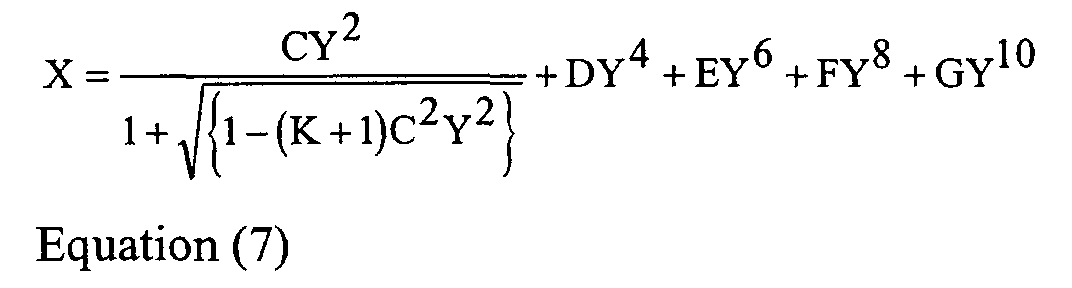
For aspheres the corrections are made on the basis of dimensional
analysis. For example, a typical design equation for aspheric surfaces is given by
where X is the sag at half-aperture ordinate Y, K is the conic constant (a shape
factor which is dimensionless), D, E, F and G are the so-called aspheric
deformation constants. C is the vertex curvature and is equivalent to the
reciprocal of the vertex radius, R. To transform Equation (7) from one describing
a lens surface to one describing a nubbin surface, the factor K L / N from Equation (6)
is used according to the dimensionality of the constant being transformed. K is a
shape factor with no dimensions. Therefore, it remains the same (a parabola
remains a parabola). C has units of reciprocal length. Therefore, it is transformed
by dividing by K L / N. D has units of reciprocal length cubed. Therefore, it is
divided by K L / N cubed, and so forth.
For a mastering system this calibration is taken one step further
where the master tool is now the working tool and the working tool is the glass
pseudo-lens. Of course, different material and temperature constants are used in
this iteration.
Because the method of the present invention involves making
optical glass elements from glass preforms, the apparent viscosity of the glass
mold tool 40 must be at least 1015 poise at the molding temperature of the optical
glass lens preforms. Since the optical glass lens preforms of interest for use with
the method of the present invention have molding temperatures in the range of
400°C to 825°C, it is necessary to mold the glass mold tool 40 from a material
with a relatively high Tg and Tm (where Tm is the temperature at which the
material has a viscosity of 1015 poise). The acceptable materials for molding glass
mold tools 40 include high silica glasses such as fused silica, fused quartz,
Vycor® and aluminosilicate glasses. Vycor® is a 96 percent silica structural
glass. Examples of aluminosilicate glasses include Corning 1723, General
Electric GE-180, Mo-Sci YAS-6, and Sem-Com SCE-3 + 5% SiO2. In order to
mold glass mold tools 40 from Vycor® or aluminosilicate glasses, it is necessary
to have a master mold tool 22 which does not deform at the molding temperatures
of the Vycor® or aluminosilicate glasses. The preferred material for
manufacturing the master mold tool 28 is silicon carbide produced by chemical
vapor deposition. For producing mold tools 40 from aluminosilicate glasses it is
also possible to use fused silica, Vycor®, or other fine grained ceramics with high
temperature characteristics such as zirconia or alumina.
As mentioned previously, release agent systems are required for
the two different molding operations. Release agent systems are a direct function
of the two materials involved and the temperature at which the two materials will
be in contact with one another. For flint glasses, the molding temperatures will be
on the order of 500°C. For crown glasses, the molding temperatures will be on
the order of 700°C. For aluminosilicate glass the molding temperature is on the
order of 900°C. For fused silica (or Vycor®) the mold temperature is on the order
of 1500°C. Silicon carbide produced by chemical vapor deposition should retain
its structural integrity up to 2600°C (in a nitrogen environment).
The preferred coating technique for the application of the tin oxide
is spin coating of a Sol-Gel and subsequent baking. There are several possible tin
oxide precursors that can be used in this manner. The gel phase allows the user
the convenience of minute additives for individual glass tuning. Also, the spin
coating technique is less susceptible to pin holes, as for example might occur in
evaporative coating. Sputtering is a further option for the application of a tin
oxide release agent coating.
The carbon coating can be done in a variety of ways. The
preferred method of carbon coating is the pyrolysis of simple hydrocarbon gases
such as methane or acetylene. Additional methods are known in the prior art
which are alleged to produce a diamond-like carbon. It is preferred to place the
release agent on the tool rather than on the preform because the preform surface is
remapped during the pressing operation. When the molding process is performed
correctly, the curvature of the preform will always be greater than the curvature of
the mold surface. In this way, the finished lens will always have a greater surface
area then the surface of the preform from which it was made. It is also possible to
coat both the preform and the tool with a carbon coating.
In the development of the method of the present invention,
experiments have shown that the apparent viscosity of the glass mold tool 40 must
be at least 1015 poise at the lens molding temperature to ensure that the shape of
the optical surface of the mold tool 40 does not change due to viscoelastic creep.
As reviewed previously, aside from high silica glasses such as fused silica, the
highest molding temperature of any commercially available optical glass is 78°C
(Schott SK5). Hence a glass with a viscosity at least 1015 poise at the lens
molding temperature is required. Using a safety factor of 40°C (to accommodate
process upsets), a glass with a 1015 poise viscosity at 825°C is required.
Furthermore, the glass mold 40 material should be deformable and moldable at a
temperature below 1100°C to preserve the master mold 28 as well as the ancillary
mold fixtures and apparatus.
Additionally, the mold glass should have a coefficient of thermal
expansion greater than 30 x 10-7/ °C and preferably above 50 x 10-7/ °C to allow
for improved release characteristics from the mold super ring 20. Second, overall
tolerances in the mold assembly 10 can be tightened. Third, the choice of the
composition of the YAS glass from which to make the glass mold tool 40 can be
made to depend upon the coefficient thermal expansion of the glass from which
the lenses are to be molded, and whether the surface is to be convex or concave.
For example, with regard to release from the mold super ring 20, if the graphite
mold super ring 20 has a CTE of 46 x 10-7/°C and the glass mold tool 40 has a
CTE of 60 x 10-7/°C, then on cool down after pressing, the glass mold tool 40
moves away from the mold super ring 20 for easy separation. With regard to the
tightening of tolerances of the mold assembly 10, for example, if the limit of
realistic tolerances for the mold assembly 10 for use is a certain value at ambient
temperature, and the two materials are similar, at molding temperature the chain
of tolerances relating one side of the lens to the other are not improved. However,
if the glass mold tool 40 material is of higher expansion than the mold super ring
20 and the master mold tool 28, then the assembly can be dimensioned at ambient
such that it will tighten up at the higher molding temperature thereby producing a
more accurate finished part.
With regard to allowing the lens glass CTE to govern the choice of
material to be used in making the glass mold tool 40, if the intended lens were
convex/concave with a 60 x 10-7/ °C CTE, it might be desirable to use the a glass
with a CTE in the range of 40 to 50 x 10-7/ °C as the base material for making the
glass molding tool 40 on the convex side and a glass with a CTE in the range of
60 to 70 x 10-7/ °C as the base material for making the glass molding tool 40 on
the concave side. In this manner, the lens glass will always be moving away from
the tool glass on cool down promoting release and a minimum wear by
eliminating any potential gripping tendency.
Additionally, the glass for the mold tool 40 should have high
hardness and chemical durability for improved polishability as the surface of the
preform used to mold the glass mold should have a surface, polished by
traditional means, better that 10-5 as measured per MIL-O-13830A. This high
surface finish ensures that the lenses replicated from the mold also have excellent
surfaces.
It is further required that the glass for the mold tool 40 be readily
manufacturable with few bubbles and inclusions after casting as well as minimal
property variation due to variation in hydroxyl content. Moisture or humidity in
the air (during the glass melting process) can affect the hydroxyl or moisture
content in the glass affecting properties such as the glass transition temperature.
Several candidate glasses were considered in this investigation as
shown below in Table 1.
| Composition of Candidate Mold Glasses |
| | | SiO2 | Al2O3 | Y2O3 | CaO | MgO | BeO |
| SCE3+5% | Alkali | <75 | <25 | | <5 | <5 | <10 |
| SiO2 | aluminosilicate |
| 7810 | Lime | 75- | 15- | | 1- |
| | aluminosilicate | 80 | 25 | | 10 |
| YAS-6 | Yttria | 33 | 25 | 42 |
| | aluminosilicate |
The properties of these glasses are shown in Table 2 below.
| Thermal Characteristics of Candidate Mold Glasses |
| | Linear thermal expansion coefficient (x107/°C) | Glass Transition Tg(°C) | Maximum use temperature (°C) (1015 poise) | Molding Temperature (°C) (108 poise) |
SCE3+5%
SiO2 | 36.6 | 807 | 762 | 1052 |
| 7810 | 22.7 | 826 | 810 | 1125 |
| YAS-6 | 55.8 | 850 | 824 | 1016 |
Ideally, fused silica, fused quartz, or other silica glasses such as
Vycor® (Corning 7913) would be selected for applications such as glass mold
tool 40. However, because of high molding temperatures of such materials (well
above 1400 °C) these materials are not compatible with the master molds 28,
tools, and apparatus (service life is poor). Furthermore, due to the aforementioned
arguments, the low coefficient of thermal expansion of these materials reduces the
suitability of these glasses for mold tool 40.
Traditionally, the glass selected for glass mold tool 40 might
include glasses from the alkali or alkaline earth aluminosilicate family. Two such
glasses, Coring 7810, and Sem-Com SCE3+5% SiO2, were experimentally
evaluated. Glass molds were successfully manufactured from these glasses and
acceptable optical lenses were molded using these glass mold tool 40. These two
glasses were found to be sufficiently refractory to mold optical glasses such as
Schott BK7, and Hoya TaC4 without any viscoelastic creep. These glasses,
however, have serious drawbacks. The high melt viscosity of these glasses (due
to the high silica content) makes it difficult to find bubbles from the melt even
when soaked at 1600°C for 24 hours (see Fig. 9). Special process were developed
to yield small batches of bubble-free glass, however, these processes are not
readily transferable to large-scale production. The high viscosity also prevents
these glasses from being readily cast into usable shapes such as slabs or boules.
Typically, because of the high silica content, these glasses have relatively low
coefficients of thermal expansion, an undesirable feature in glass for mold tool 40.
Additionally, alkali and alkaline earth aluminosilicates have substantial variations
in Tg with composition or hydroxyl content.
To overcome the aforementioned problems, a little known glass
system, called rare earth aluminosilicates, was investigated. The rare earth
elements include the following: Ce, Pr, Nd, Pm, Sm, Eu, Gd, Tb, Dy, Ho, Er, Tm,
Yb, and Lu. Yttrium is often included in such discussions because it behaves
much like a rare earth element even though it is technically not. For the purposes
of this application the term "rare earth elements" is intended to include yttrium.
Binary systems of silica and rare earth oxides are notoriously difficult to
manufacture because of liquid immiscibility and phase separation. Ternary
systems, however, are amenable to glass formation and fabricating. One of the
salient characteristics of rare earth aluminosilicate glasses is their higher glass
transition temperature (see Fig. 10 which is from Shelby, J. E., Kohli, J. T., "Rare
Earth Aluminosilicate Glasses" J. American Ceramic Soc. Vol 73, No. 1. 1990,
pp. 39-42.). It surprisingly has been found that such rare earth aluminosilicate
glasses also have a low melt viscosity. Further, such glasses are quite fluid (see
Fig. 9) at normal processing temperatures (1600-1700 °C) and bubble-free melts
may therefore be obtained in relatively short times (in a matter of minutes
typically). The high fluidity of these glasses, however, does significantly increase
the propensity for crystallization. This characteristic affects the size of the slabs
that may be cast from a melt.
The uniqueness of the rare earth aluminosilicate glasses stems from
the rare earth cations. The high field strength of the rare earth modifier cations
leads to highly disordered structures and significant variability in the bond angles
and morphology of the silicon-oxygen tetrahedra in this class of glass. In essence,
there is significantly more structural disorder in rare earth aluminosilicates glasses
compared with alkali and alkaline earth aluminosilicates. Until recently it was not
known that rare earth aluminosilicate glasses could be formed. The classical
understanding of glass formation suggests that rare earth aluminosilicates should
not form glasses at all.
Rare earth aluminosilicates contain significant levels of
nonbridging oxygen atoms. Alkali aluminosilicates on the other hand contain
very few nonbridging oxygens (for glasses with equimolar alkali oxide and
alumina concentrations). It is also interesting to note that with yttria composition
changes in yttria aluminosilicates, there is only a very small variation in the
concentration of nonbridging oxygens. In yttria aluminosilicate glasses, it is
believed that the high nonbridging oxygen concentrations are responsible for the
high melt fluidity of these glasses as well as their low Tg variation with yttria
concentration.
An yttria aluminosilicate glass, YAS-6, is a preferred glass for
glass molds because of its combination of properties. Of the rare earth
aluminosilicate glasses, the yttria aluminosilicate glasses have higher glass
transition temperatures and lower coefficients of thermal expansion. Furthermore,
yttria aluminosilicates have well behaved properties compared with other rare
earth silicates. For example, the coefficient of thermal expansion increases
generally linearly with yttria concentration from 25 to 70 x 10-7/ °C (see Fig. 11
which is from Shelby, J. E., et al., "Formation and Properties of Yttrium
Aluminosilicate Glasses." Physics and Chemistry of Glasses, Vol. 33, No. 3,
1992, pp.93-98). Based on limited data, the CTE of other rare earth silicates
varies widely and irregularly with composition. Similarly, the Tg of yttria
aluminosilicates is very stable with composition as shown in Fig. 12 (which is
from Shelby J. E., et al., "Formation and Properties of Yttrium Aluminosilicate
Glasses." Physics and Chemistry of Glasses, Vol. 33, No. 3, 1992, pp.93-98.).
Therefore, while the method of the present invention may be practicable with
other rare earth aluminosilicate glasses, some experimentation may be required to
achieve the compositions of such glasses which will have the desired properties
for a particular application.
As previously mentioned, one of the difficulties with alkali
aluminosilicate glasses is adhesion of the release coating. Traditionally a carbon-based
release coating is used to prevent the molded lens from bonding to the tool
(particularly crown glasses). Experiments have shown that when a carbon-based
coating was applied directly to the surface of an alkali aluminosilicate mold
(SCE3+5% SiO2), the adhesion of this coating was very inconsistent. Some
molds would have acceptable life (greater than 250 cycles) before the coating
failed and some failed in only a few cycles (see Fig. 14). To correct this problem,
a 1000 Å layer of silicon carbide was coated on the surface prior to the deposition
of the carbon-based coating. Tools coated in this way have significantly
improved life.
It was, however, discovered that yttria aluminosilicate molds were
much more receptive to carbon-based coatings. In early experiments, tools coated
with carbon (by physical vapor deposition) lasted between 210 to 360 cycles.
When a 1000 Å layer of silicon carbide was applied to the glass mold prior to the
carbon-based coating, the coating life improved to 250 to 350 cycles (see Fig. 13).
In simulated production runs, it is not uncommon for a tool to last more than 600
cycles before failing. When a tool does fail, it is generally because of scratches
and other surface defects rather than coating adhesion. It is believed that the
excellent hydrolytic stability as well as the absence of alkali in the yttria
aluminosilicate glass enhances the coating adhesion and durability. This
observation was further verified by comparing the adhesion of carbon films on
borosilicate and fused silica glasses. In such studies, coatings always bonded well
to the fused silica but not necessarily to the borosilicate.
In an exemplary application, biaspheric, double convex, digital
camera lenses (6.96mm diameter by 2.01mm center thickness) were molded using
upper and lower glass molds fabricated from a yttria aluminosilicate glass (YAS)
as shown in Table 3. This lens was molded from Schott BK7 optical glass.
The properties of this glass are shown in Table 4.
| Thermal Characteristics of YAS Mold Glasses |
| Material Identification | Linear thermal expansion coefficient (x107/°C) | Glass Transition Tg (°C) | Maximum use temperature (°C) (1015 poise) | Molding Temperature (°C) (108 poise) |
| YAS-6 | 55.8 | 850 | 824 | 1016 |
The glass working molds were molded using CVD silicon carbide master molds
of the inverse shape. The silicon carbide master molds were fabricated using
traditional diamond grinding and aspheric polishing techniques. The master tools
were then coated with a suitable release agent. Cylindrical preforms were
fabricated from YAS-6 glass and one end of each preform was polished by
traditional means to a scratch rating of 10, and a dig rating of 5 per MIL-PRF-13830.
The preforms were then coated with a pyrolytic release coating. To mold
the upper and lower working molds from YAS-6, the coated preforms were placed
in the molding apparatus (see Fig. 7) such that the polished end of the preform
faced the master tool surface. The mold system was then enveloped in a nitrogen
atmosphere and was heated to 1020°C. Once the mold and the preform were
heated to 1020°C the mold halves are slowly closed, molding the preform into the
desired shape (see Fig. 8). The mold was then cooled and the glass mold was
removed. The glass molds were then vacuum coated with 640Å of silicon carbide
and subsequently 1500Å of carbon. The YAS-6 glass working molds were then
placed in a molding machine and lenses were molded from Schott BK7 spherical
preforms at 700°C (a viscosity of 108 poise). Prior to molding the lenses, the
Schott BK7 spherical preforms were coated with a pyrolytic release layer. After
molding the pyrolytic release coating was removed from the surfaces of the
lenses. The lenses were then optically centered by traditional methods and
cleaned. Lenses produced in this manner were found to be suitable for the end use
product.