EP1157846A2 - Method and apparatus for bearing hub alignment in print engine chassis - Google Patents
Method and apparatus for bearing hub alignment in print engine chassis Download PDFInfo
- Publication number
- EP1157846A2 EP1157846A2 EP01201794A EP01201794A EP1157846A2 EP 1157846 A2 EP1157846 A2 EP 1157846A2 EP 01201794 A EP01201794 A EP 01201794A EP 01201794 A EP01201794 A EP 01201794A EP 1157846 A2 EP1157846 A2 EP 1157846A2
- Authority
- EP
- European Patent Office
- Prior art keywords
- bearing hub
- filler material
- imaging drum
- cavity
- wall
- Prior art date
- Legal status (The legal status is an assumption and is not a legal conclusion. Google has not performed a legal analysis and makes no representation as to the accuracy of the status listed.)
- Withdrawn
Links
Images


Classifications
-
- B—PERFORMING OPERATIONS; TRANSPORTING
- B41—PRINTING; LINING MACHINES; TYPEWRITERS; STAMPS
- B41J—TYPEWRITERS; SELECTIVE PRINTING MECHANISMS, i.e. MECHANISMS PRINTING OTHERWISE THAN FROM A FORME; CORRECTION OF TYPOGRAPHICAL ERRORS
- B41J11/00—Devices or arrangements of selective printing mechanisms, e.g. ink-jet printers or thermal printers, for supporting or handling copy material in sheet or web form
- B41J11/02—Platens
- B41J11/04—Roller platens
Definitions
- This invention relates in general to a color proofing apparatus and method of manufacture and more particularly to alignment of a bearing hub in a print engine chassis.
- Pre-press color proofing is a procedure used by the printing industry for creating representative images of printed material. This procedure avoids the high cost and time required to produce printing plates and also avoids setting-up a high-speed, high-volume printing press to produce a representative sample of an intended image for proofing. Otherwise, in the absence of pre-press proofing, a production run may require several corrections and must be reproduced several times to satisfy customer requirements. This results in lost profits. By utilizing pre-press color proofing, time and money are saved.
- a laser thermal printer having half-tone color proofing capabilities is disclosed in commonly assigned U.S. Patent No. 5,268,708 titled "Laser Thermal Printer With An Automatic Material Supply” issued December 7, 1993 in the name of R. Jack Harshbarger, et al.
- the Harshbarger, et al. device is capable of forming an image on a sheet of thermal print media by transferring dye from a roll of dye donor material to the thermal print media. This is achieved by applying thermal energy to the dye donor material to form the image on the thermal print media.
- This apparatus generally comprises a material supply assembly, a lathe bed scanning subsystem (which includes a lathe bed scanning frame, a translation drive, a translation stage member, a laser printhead, and a rotatable vacuum imaging drum), and exit transports for thermal print media and dye donor material.
- a lathe bed scanning subsystem which includes a lathe bed scanning frame, a translation drive, a translation stage member, a laser printhead, and a rotatable vacuum imaging drum
- the operation of the Harshbarger, et al. apparatus comprises metering a length of the thermal print media (in roll form) from a material supply assembly.
- the thermal print media is then measured and cut into sheet form of the required length, transported to the vacuum imaging drum, registered, and then wrapped around and secured onto the vacuum imaging drum.
- a length of dye donor roll material is also metered out of the material supply assembly, measured and cut into sheet form of the required length.
- the cut sheet of dye donor roll material is then transported to and wrapped around the vacuum imaging drum, such that it is superposed in registration with the thermal print media, which at this point has already been secured to the vacuum imaging drum.
- the drum is rotated past the printhead and the translation drive traverses the printhead and translation stage member axially along the rotating vacuum imaging drum in coordinated motion with the rotating vacuum imaging drum. These movements combine to produce the image on the thermal print media.
- the dye donor material is removed from the vacuum imaging drum without disturbing the thermal print media. Additional dye donor materials are sequentially superposed with the thermal print media on the vacuum imaging drum, then imaged onto the thermal print media as previously mentioned, until the intended full-color image is completed.
- the printer disclosed in the Harshbarger, et al. patent performs well, there is a long-felt need to reduce manufacturing costs for this type of printer and for similar types of imaging apparatus.
- the machined casting used as the frame represents significant cost relative to the overall cost of the printer. Cost factors include the design and fabrication of the molds, the casting operation, and subsequent machining needed in order to achieve the precision necessary for a lathe bed scanning engine used in a printer of this type.
- Castings can be complex to model, making it difficult to use tools such as finite element analysis to predict the suitability of a design, Moreover, due to shrinkage, porosity, and other manufacturing anomalies, careful mold maintenance may be required in order to obtain uniform results when casting multiple frames. In the assembly operation, each frame casting must be individually assessed for its suitability to manufacturing standards and must be individually machined. Further, castings also exhibit frequency response behavior due to resonant frequencies, which are difficult to analyze or predict. For this reason, the task of identifying and reducing vibration effects can require considerable work and experimentation. Additionally, the overall amount of time required between completion of a design and delivery of a prototype casting can be several weeks or months.
- castable polymers manufactured under a number of trade names, have been employed to provide support structures that are equivalent to castings for apparatus such as machine tool beds and optical tables. These castable polymers also provide improved performance when compared with castings, with respect to expansion and contraction due to heat and with respect to vibration damping.
- Castable polymers have been employed to provide substitute structures for metal castings and weldments.
- U.S. Patent No. 5,415,610 Schoutz et al.
- U.S. Patent Nos. 5,678,291 Braun
- 5,110,283 Bluml et al.
- Castable polymers are also used in the machine tool environment for damping mechanisms, as is disclosed in U.S. Patent No. 5,765,818 (Sabatino et al.)
- Castable polymers provide a number of advantages, including the ability to mount support components of the chassis directly in the castable material when it is still soft.
- Various types of fasteners, tubing, or other components can be cast in place, or can even be inserted into the castable polymer before it hardens.
- Of particular difficulty, however, is the precision placement of support components within the castable polymer material.
- In order to precisely position a component within such a material used as filler in a chassis it is necessary to employ some type of temporary fixture or jig to hold the component in place temporarily during the hardening process. This positioning problem is compounded when it is necessary to mount two or more support components that must be axially aligned with respect to each other, such as the bearing hubs that support each end of an imaging drum.
- Components can be mounted in a castable concrete polymer that holds them in position, as is disclosed for attachment elements in a band saw in U.S. Patent No. 4,557,171 (Stolzer).
- precision positioning can be effected.
- U.S. Patent No. 4,425,171 discloses use of a substantially non-fluid bonding component (for example, epoxies) for precision positioning.
- the methods and materials disclosed in the Oosaka patent are intended primarily for service with lightweight optical components. These can be positioned by hand, as noted in the Oosaka et al. patent disclosure.
- a method of aligning a bearing hub in a print engine chassis supporting an imaging drum provides a right wall positioned near a first end of the imaging drum and has a first cavity near the first end of the imaging drum.
- the present invention also provides a left wall positioned near a second end of the imaging drum, the left wall substantially parallel to said right wall, wherein the left wall has a second cavity near the second end of the imaging drum.
- a self-hardening filler material is poured into the first and second cavities.
- a right bearing hub is positioned for the imaging drum into the filler material within the first cavity prior to hardening of the filler material.
- a left bearing hub is positioned for the imaging drum into the filler material within the second cavity prior to hardening of the filler material. Alignment of the left bearing hub with the right bearing hub is needed.
- a precision mandrel is employed to axially align the bearing hubs, the mandrel itself supported on a fixture.
- a jackscrew positions the bearing hub on the mandrel before casting with filler material to allow removal of the mandrel when the filler material hardens.
- a feature of the present invention is the provision of a print engine chassis comprising a filler material, wherein split bearing hubs are used to support bearings for the imaging drum, the bearing hubs themselves rigidly set in castable filler material.
- An advantage of the present invention is that it eliminates the need for precision line boring machining for the purpose of creating axially aligned bores in facing chassis walls. Instead, modular split bores are set in castable filler material during chassis fabrication.
- Yet another advantage of the present invention is that parts can be added to a chassis during assembly, at the time the castable polymer filling is applied. This saves cost over machining and allows changes to be easily incorporated into the design.
- Figure 1 is a perspective view of a sheet metal structure in the preferred embodiment of this invention.
- Figure 2 is a perspective view of a sheet metal structure with a filler material poured into selected cavities.
- Figure 3 is a perspective view of a print engine having an imaging drum, printhead translation assembly, and associated motors.
- Figure 4 is a perspective view of a bearing hub of the present invention.
- Figure 5 is a flat side view of the bearing hub shown in Figure 4.
- Figure 6 is a cross-sectional along lines 6-6 view of the bearing hub of Figure 5.
- Figure 7 is a top plan view showing a fixture used for bearing hub alignment during fabrication.
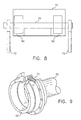
- Figure 8 is a side view showing the fixture used for bearing hub alignment.
- Figure 9 is a perspective view of a jackscrew positioned within the bearing hub.
- a sheet metal frame 12 that forms a skeleton for the chassis of a print engine.
- sheet steel of 0.090 inch thickness (nominal) is used to provide strength.
- Sheet steel members can be cut from stock using laser cutting techniques, well known in the sheet metal art.
- Sheet metal frame 12 comprises side walls 22a and 22b, inner walls 24a and 24b, a rear wall 26, and a front member 28 atop a base 64.
- Sheet metal frame 12 further comprises supporting and bracing structures provided by full-length cross-struts 30a and 30b and cross braces 20a and 20b.
- a left cross-strut 34 spans between side wall 22b and inner wall 24b.
- a right cross-strut 32 spans between side wall 22a and inner wall 24a.
- a slot 38 is provided at each junction of sheet metal members.
- slot 38 mates with a corresponding slot 38 on a joining member, or slot 38 is fitted to a tab 36.
- a bracing box 56 having a slot at each vertical corner fits about the junction of cross braces 20a and 20b.
- Side wall 22a and inner wall 24a form a right side cavity 58.
- Side wall 22b and inner wall 24b form a left side cavity 60.
- inner wall 24a could be disposed further to the left within sheet metal frame 12. This might be preferable, for example, where the weight of supported motor structures requires additional support.
- inner wall 24a could be suitably repositioned in a number of different locations, at different distances from side wall 22a.
- the overall dimensions of sheet metal frame 12 could be altered while using many of the same sheet metal members. For example, the length of a chassis frame could be changed simply by altering the lengths of full-length cross strut 30a, front member 28, and rear wall 26.
- Figure 2 shows sheet metal frame 12 reinforced using the method of the present invention.
- a filler material 54 is poured into left side and right side cavities 60 and 58, into bracing box 56, and into troughs formed by left cross-strut 34, full-length cross-struts 30a and 30b, and right cross strut 32 within sheet metal frame 12.
- Filler material 54 is also poured into front member 28. Filler material 54 hardens and locks sheet metal members of sheet metal frame 12 rigidly into place.
- Filler material 54 is preferably a castable polymer concrete, such as SUPER ALLOY Polymer Concrete manufactured by Philadelphia Resins, located in Montgomeryville, PA.
- Castable polymer substances such as the "SUPER ALLOY” mixture provide a stable structure for the print engine chassis.
- castable polymer concrete is particularly well suited, since this substance provides excellent vibration damping.
- aggregate size can be changed, castable polymer concrete can be modified to optimize vibration response characteristics for specific equipment applications.
- tabs 36 include holes to allow flow-through of the castable polymer when poured. Upon hardening, a channel of the castable polymer fills the hole, further locking tab 36 into place.
- various mounting components can be embedded within the castable polymer concrete.
- embedded components are locked into position. This technique is used for parts that require precision alignment, effectively using the castable polymer concrete to lock components precisely into place.
- Tubing may also be inserted within a cavity to allow routing of wires or air flow circulation through the polymer concrete material.
- a print engine 10 having an imaging drum 14, driven by a drum motor 16.
- Drum 14 is mounted to rotate within a left bearing hub 50 and a right bearing hub 52 that support drum bearings (not shown). Both left bearing hub 50 and right bearing hub 52 are held in place by the castable polymer concrete that acts as filler material 54 within right side cavity 58 and left side cavity 60.
- a translation motor 18 drives a printhead transport 40 containing a printhead 42 by means of a lead screw 44.
- a front guide rail 46 and a rear guide rail 48 support printhead transport 40 over its course of travel from left to right as viewed in Figure 3.
- Figure 4 shows right bearing hub 52 in perspective view.
- Right bearing hub 52 is cast from steel in the preferred embodiment, and is machined to provide a split section 68 for allowing the seating of imaging drum 14. Through holes 66 are provided in bearing hub 52 for filling by castable filler material 54, as is described subsequently.
- Figure 5 shows a flat side view of right bearing hub 52.
- Figure 6 shows a cross-section view of right bearing hub 52 taken across section 6-6 marked in Figure 5.
- bearing hub 52 is held in position by filler material 54.
- Left bearing hub 50 is also held in position by filler material 54.
- left bearing hub 50 is also split; however, left bearing hub 54 could be continuous, as shown in Figure 3.
- Fixture 71 is comprised of a mandrel 70 and y-shaped brackets 72.
- Mandrel 70 is precision-machined to serve as an alignment element.
- Y-shaped brackets 72 are disposed on either side of sheet metal frame 12 to hold mandrel 70 level and at the correct height for bearing hub 50 and 52 alignment.
- a jackscrew 74 is inserted within a split section 68 as shown in Figure 9. Jackscrew 74 spreads split section 68 slightly to allow fitting of hubs 50 and 52 onto mandrel 70. Jackscrew 74 is removed when hubs 50 and 52 are properly positioned. Filler material 54 is then poured into cavities in sheet metal frame 12.
Landscapes
- Rolls And Other Rotary Bodies (AREA)
- Electronic Switches (AREA)
- Accessory Devices And Overall Control Thereof (AREA)
Abstract
Description
Further, castings also exhibit frequency response behavior due to resonant frequencies, which are difficult to analyze or predict. For this reason, the task of identifying and reducing vibration effects can require considerable work and experimentation. Additionally, the overall amount of time required between completion of a design and delivery of a prototype casting can be several weeks or months.
Claims (10)
- A method of aligning a bearing hub in a print engine chassis for supporting an imaging drum comprising the steps of:providing a right wall positioned near a first end of said imaging drum and having a first cavity near said first end of said imaging drum;providing a left wall positioned near a second end of said imaging drum, said left wall substantially parallel to said right wall, wherein said left wall has a second cavity near said second end of said imaging drum;pouring a self-hardening filler material into said first and second cavities;positioning a right bearing hub for said imaging drum into said filler material within said first cavity prior to hardening of said filler material;positioning a left bearing hub for said imaging drum into said filler material within said second cavity prior to hardening of said filler material; andaligning said left bearing hub with said right bearing hub.
- A method as in claim 1 wherein a mandrel is inserted in said right bearing hub and said second bearing hub for alignment of said hubs.
- The method of claim 1 wherein said right bearing hub is a split bearing hub.
- The method of claim 3 wherein said right bearing hub is split by a jackscrew prior to insertion of a mandrel for alignment of said right bearing hub and said left bearing hub.
- The method of claim 1 wherein said left bearing hub and said right bearing hub are split bearing hubs.
- The method of claim 1 wherein said filler material is a castable polymer concrete.
- A print engine chassis for supporting an imaging drum comprising:a right wall containing a first cavity adapted for accepting a castable filler material in pliable form wherein said right wall is disposed at a normal with respect to an axis of said imaging drum;a left wall, disposed opposite said right wall and parallel to said right wall, said left wall containing a second cavity adapted for accepting said filler material in pliable form;a right bearing hub for supporting said axis of said imaging drum, said right bearing hub held in place by said filler material within said first cavity of said right wall after said filler material hardens; anda left bearing hub for supporting said axis of said imaging drum, said left bearing hub held in place by said filler material within said second cavity of said left wall after said filler hardens.
- The print engine chassis of claim 7 wherein said filler material is a castable polymer concrete.
- The print engine chassis of claim 7 wherein said right bearing hub comprises at least one cavity capable of being filled with said filler material.
- The print engine chassis of claim 7 wherein said right bearing hub and said left bearing hub are axially aligned.
Applications Claiming Priority (2)
| Application Number | Priority Date | Filing Date | Title |
|---|---|---|---|
| US09/579,382 US6364555B1 (en) | 2000-05-26 | 2000-05-26 | Method and apparatus for bearing hub alignment in print engine chassis |
| US579382 | 2000-05-26 |
Publications (2)
| Publication Number | Publication Date |
|---|---|
| EP1157846A2 true EP1157846A2 (en) | 2001-11-28 |
| EP1157846A3 EP1157846A3 (en) | 2002-04-03 |
Family
ID=24316672
Family Applications (1)
| Application Number | Title | Priority Date | Filing Date |
|---|---|---|---|
| EP01201794A Withdrawn EP1157846A3 (en) | 2000-05-26 | 2001-05-14 | Method and apparatus for bearing hub alignment in print engine chassis |
Country Status (3)
| Country | Link |
|---|---|
| US (1) | US6364555B1 (en) |
| EP (1) | EP1157846A3 (en) |
| JP (1) | JP2002061633A (en) |
Families Citing this family (4)
| Publication number | Priority date | Publication date | Assignee | Title |
|---|---|---|---|---|
| US6634819B2 (en) * | 2000-07-21 | 2003-10-21 | Canon Kabushiki Kaisha | Recording apparatus with modular housing components |
| DE60016203T2 (en) * | 2000-08-24 | 2005-11-24 | Hewlett-Packard Development Co., L.P., Houston | Guide bar for print carriage |
| US6439787B1 (en) * | 2000-12-28 | 2002-08-27 | Eastman Kodak Company | Sheet metal print engine chassis assembled without fasteners |
| JP2007176122A (en) * | 2005-12-28 | 2007-07-12 | Brother Ind Ltd | Carriage scanning device and image forming apparatus |
Family Cites Families (23)
| Publication number | Priority date | Publication date | Assignee | Title |
|---|---|---|---|---|
| US2464082A (en) * | 1946-12-31 | 1949-03-08 | William C Hart | Method of casting printing rollers |
| DE1293321B (en) * | 1963-04-29 | 1969-04-24 | Licentia Gmbh | Small electric motor |
| BE788184A (en) * | 1971-03-15 | 1973-02-28 | Tru Line | TRANSMISSION SYSTEM BEARING ALIGNMENT PROCESS |
| FR2332453A1 (en) * | 1975-11-19 | 1977-06-17 | Bretagne Atel Chantiers | Bearing mounting in gearbox case - has bearing position screw adjusted before epoxy resin is added for locking |
| JPS5778004A (en) | 1980-10-31 | 1982-05-15 | Fuji Photo Film Co Ltd | Method for precise positioning |
| FR2497302A1 (en) * | 1980-12-29 | 1982-07-02 | Skf Cie Applic Mecanique | Precision machine tool spindle - has injected resin housings for bearing bushes in shells |
| US4451186A (en) | 1981-04-06 | 1984-05-29 | Payne Charles L | Tool for use in line boring of diesel engine blocks |
| US4593587A (en) | 1981-07-13 | 1986-06-10 | The Warner & Swasey Company | Machine tool utilizing force transmitting joints |
| IT1180682B (en) | 1983-04-26 | 1987-09-23 | Keuro Maschinenbau Gmbh | BAND SAWING MACHINE |
| US4616944A (en) * | 1984-06-11 | 1986-10-14 | International Business Machines Corporation | Printer frame assembly and method of assembly |
| US4723857A (en) * | 1984-11-20 | 1988-02-09 | Brother Kogyo Kabushiki Kaisha | Printer with a plastic frame structure |
| US4846595A (en) * | 1986-05-28 | 1989-07-11 | Ricoh Co., Ltd. | Frame structure of a printer with positioning openings |
| US4693642A (en) | 1986-07-02 | 1987-09-15 | General Motors Corporation | Line boring apparatus |
| US4825022A (en) * | 1986-10-27 | 1989-04-25 | Labworks Inc. | Mail sorting computer keyboard |
| DE3718106A1 (en) | 1987-05-27 | 1988-12-15 | Mannesmann Ag | PRECISION CLOSING UNIT FOR AN INJECTION MOLDING MACHINE |
| US4979850A (en) | 1988-11-01 | 1990-12-25 | Olman Dompe | Apparatus for precision line boring of engines and like mechanisms |
| US5268708A (en) | 1991-08-23 | 1993-12-07 | Eastman Kodak Company | Laser thermal printer with an automatic material supply |
| JP2646512B2 (en) * | 1991-12-25 | 1997-08-27 | アスモ株式会社 | Resin injection bearing for small motor |
| DE4230502C1 (en) | 1992-09-14 | 1994-03-10 | Steinel Bernhard Werkzeugmasch | Machine frame for a machining center |
| JPH06317953A (en) * | 1993-04-28 | 1994-11-15 | Canon Inc | Frame structure and image forming device |
| DE4441252B4 (en) | 1994-11-19 | 2006-01-26 | Maschinenfabrik Berthold Hermle Ag | Machine tool, in particular drilling and milling machine |
| US5765818A (en) | 1996-07-17 | 1998-06-16 | Sabatino; David B. | Vibration damping structure for use with a machine tool |
| US5775825A (en) * | 1996-07-22 | 1998-07-07 | Hewlett-Packard Company | Integrated shell-and-chasis construction for a desktop image-related device |
-
2000
- 2000-05-26 US US09/579,382 patent/US6364555B1/en not_active Expired - Fee Related
-
2001
- 2001-05-14 EP EP01201794A patent/EP1157846A3/en not_active Withdrawn
- 2001-05-25 JP JP2001157379A patent/JP2002061633A/en active Pending
Also Published As
| Publication number | Publication date |
|---|---|
| EP1157846A3 (en) | 2002-04-03 |
| US6364555B1 (en) | 2002-04-02 |
| JP2002061633A (en) | 2002-02-28 |
Similar Documents
| Publication | Publication Date | Title |
|---|---|---|
| CA1216464A (en) | Screen printing frame | |
| US6203224B1 (en) | Print engine chassis for supporting a vacuum imaging drum | |
| US20020007928A1 (en) | Process and a system for connecting at least two components | |
| US6476843B2 (en) | Reinforced sheet metal frame incorporating print engine chassis | |
| US6364555B1 (en) | Method and apparatus for bearing hub alignment in print engine chassis | |
| WO1985004057A1 (en) | Synchronous electric rotary machine | |
| CA1294597C (en) | Structural element for a machine tool | |
| CZ2012967A3 (en) | Process for producing railway car swing beam | |
| CZ2012964A3 (en) | Process for producing side frame of railway car undercarriage | |
| US6427310B1 (en) | Method for fabricating a print engine chassis for supporting an imaging drum and printhead translation assembly | |
| GB2264365A (en) | "photoplotter drum" | |
| JPH0842305A (en) | Exchanging method of mechanical section | |
| US6439787B1 (en) | Sheet metal print engine chassis assembled without fasteners | |
| CZ2012966A3 (en) | Process for producing railway car swing beam | |
| US6389969B1 (en) | Print engine chassis having adjustable sidewall thickness | |
| JPH074645B2 (en) | Method and apparatus for assembling mold part, especially core | |
| US3599313A (en) | Frame and yoke assembly for high-speed printers and method of making same | |
| DE60315439T2 (en) | DEVICE FOR CARRYING THE SPINDLE IN A TOOL MACHINE AND METHOD FOR THE PRODUCTION THEREOF | |
| JPH03258442A (en) | Electromagnetic braking device for continuous casting mold | |
| CN223735145U (en) | A modular steel bar binding jig | |
| EP1747979B1 (en) | Reinforced upper frame for supporting cabin of heavy construction equipment using welding deformation preventing structure, and method of manufacturing the same | |
| JPH06234042A (en) | Core assembly method | |
| JPH11230129A (en) | Method for fixing guide member to support, guide device obtained thereby, and marking device having device thereof | |
| JP2568317B2 (en) | Storage rack for spent fuel | |
| DE102008021692B4 (en) | Process for the production of a surface for printing machines and a drum cap for transfer drums in printing machines |
Legal Events
| Date | Code | Title | Description |
|---|---|---|---|
| PUAI | Public reference made under article 153(3) epc to a published international application that has entered the european phase |
Free format text: ORIGINAL CODE: 0009012 |
|
| AK | Designated contracting states |
Kind code of ref document: A2 Designated state(s): DE Kind code of ref document: A2 Designated state(s): AT BE CH CY DE DK ES FI FR GB GR IE IT LI LU MC NL PT SE TR |
|
| AX | Request for extension of the european patent |
Free format text: AL;LT;LV;MK;RO;SI |
|
| PUAL | Search report despatched |
Free format text: ORIGINAL CODE: 0009013 |
|
| AK | Designated contracting states |
Kind code of ref document: A3 Designated state(s): AT BE CH CY DE DK ES FI FR GB GR IE IT LI LU MC NL PT SE TR |
|
| AX | Request for extension of the european patent |
Free format text: AL;LT;LV;MK;RO;SI |
|
| 17P | Request for examination filed |
Effective date: 20020905 |
|
| AKX | Designation fees paid |
Free format text: DE |
|
| 17Q | First examination report despatched |
Effective date: 20030212 |
|
| STAA | Information on the status of an ep patent application or granted ep patent |
Free format text: STATUS: THE APPLICATION IS DEEMED TO BE WITHDRAWN |
|
| 18D | Application deemed to be withdrawn |
Effective date: 20030624 |